
Abstract
The kinetics of carbide free layer formation in a process heater tube made of Fe–Ni–Cr austenitic steel during high temperature service exposure has been studied. An integrated scanning electron microscopy–energy dispersive spectroscopy–electron backscatter diffraction system was used for microstructural and compositional analysis of the investigated alloy tubes. A diffusion based model has been proposed to estimate the surface temperatures based on the widths of the respective carbide free layers. The model would be useful to predict the chromium concentration profiles at various times to prevent catastrophic failure of the material.
Introduction
The phenomenon of chromium redistribution in Fe–Ni–Cr alloys has been investigated for the last 60 years. The reason behind these studies was to investigate the predominantly intergranular corrosion behaviour of this important class of materials. The loss of chromium in the regions beside the grain boundaries in the alloys can lead to severe intergranular attack in aqueous environments. The earlier investigations were mostly focused either on stainless steels1 – 4 or on Ni based superalloys.5 Fe–Ni–Cr alloy is commonly used for high temperature applications in petrochemical plants as process heater tubes. The Nb modified Fe–Ni–Cr austenitic steel is commercially known as HP-40 steel. The effect of Nb and C on the solidification of Fe–Ni–Cr alloy is available in the literature.6
Petrochemical cracking processes are carried out in large furnaces where pressurised mixtures of hydrocarbon feedstock, steam and air are passed through long reaction tubes or coils. Since the desired reactions are highly endothermic in nature, these radiant coils have to be maintained at high temperatures (1000-1350 K). This is a continuous process, and the tubes have design lives of ∼100 000 h or ∼10 years. However, while in service, these tubes are subjected to a range of damage mechanisms not considered in the design computations that shorten their lives. The creep and tensile behaviour of reformer tubes made of HP-40 austenitic steel was studied by Voicu et al.7 Because of the high operating temperature and the chemistry of the actual hydrocracking process, the inner surface of these coils is constantly subjected to a carburising atmosphere. Carbon is picked up by the inner surface from the gas stream itself as well as the layer of coke, which gradually deposits on the inner surface. 8 8,9 As this coke layer is a major hindrance to the heat transfer, the outside wall temperature has to be raised to ensure adequate supply of thermal energy to the hydrocarbon feedstock. When the thickness of the coke layer becomes unacceptably high, decoking is carried out. During the decoking cycle, a mixture of steam and air is passed through these coils instead of the hydrocarbon feedstock. Additionally, the outer surface of these tubes is subjected to oxidation damage. These damage processes, carburisation as well as oxidation eventually lead to loss of chromium from the matrix and subsequent dissolution of chromium carbide precipitates near both of the tube walls. 10 10,11 This evolution of carbide free layers near both the walls results in loss of mechanical strength as well as corrosion resistance of these tubes. The loss of chromium due to high temperature service exposure of the tubes leading to reduction in strength causes catastrophic fracture of the tubes. Therefore, it is important to understand the kinetics of chromium depletion and the rate of growth of the carbide free layers in the tubes.
In this work, a diffusion based model has been developed to estimate the effective average temperature of the outer and inner walls and predict the width of the carbide free layers for various service tenures.
Experimental
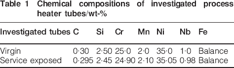
The chemical compositions of the investigated process heater tubes made of Fe–Ni–Cr austenitic steel are given in Table 1.
Chemical compositions of investigated process heater tubes/wt-%
Scanning electron microscopy (SEM; JEOL JSM-840A and Hitachi S-3400N), energy dispersive spectroscopy (EDS; Thermo Electron NSS-300 and Thermo Noran Quest) and electron backscatter diffraction (HKL Channel 5) were used for the microstructural analysis of the virgin and service exposed (20 000 h at 1373 K) tubes. The outer and inner diameters of these tubes are 73 and 56 mm respectively. The tube wall thickness is 8·5 mm. The cross-section of the tubes was cut and polished for metallographic study under SEM.
Results and discussion
The carbide precipitates in the virgin material are identified as mainly Cr7C3 at the grain boundaries and small fraction of tiny NbC inside the grains, as shown in Fig. 1. An interactive method available in electron backscatter diffraction coupled with EDS with a step size of 100 nm was used for phase identification. Carbide free zones near both inner and outer surfaces were observed in the service exposed tubes, whereas there was no carbide free zones in the virgin tube. The width of the external and internal carbide free layers was found to be varied with exposed time of the tubes. The cross-sectional microstructures of service exposed tube are shown in Fig. 2. Cr23C6 carbides and G phases (Ni6Nb16Si11) were observed in the service exposed tubes, as shown in Fig. 3. It is found that Cr7C3 carbides were transformed to Cr23C6 carbides and NbC carbides were transformed to G phases respectively due to service exposed at high temperature for a longer period. It is reported that due to service exposure at higher temperature for a longer period, the transformation of NbC to G phase occurred.12 – 16
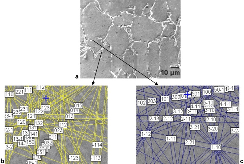
Image (SEM) and indexed Kikuchi pattern of virgin Fe–Cr–Ni process heater tube showing a microstructure, b Cr7C3 and c NbC carbide

Images (SEM) of 20 000 h service exposed Fe–Ni–Cr process heater tube showing carbide free layer of a outer and b inner sides of tube
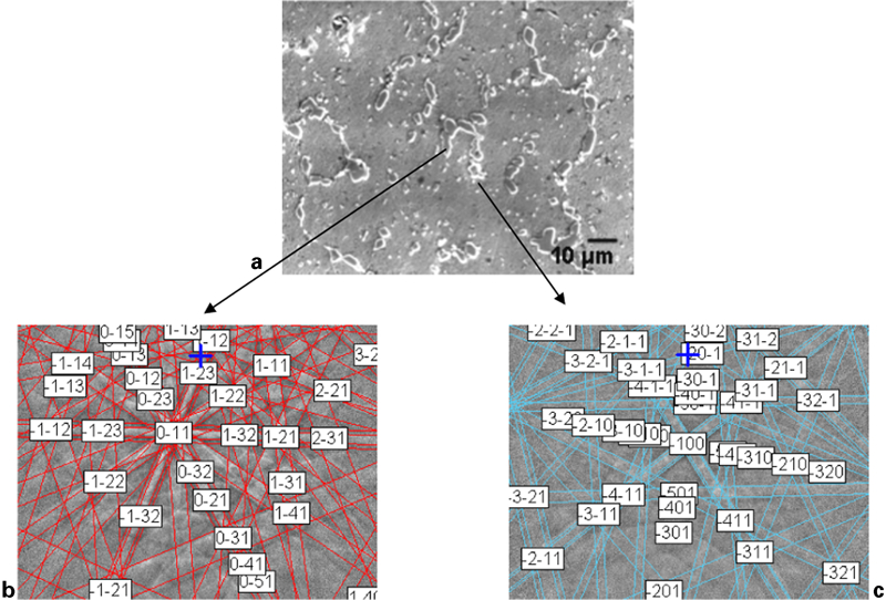
Image (SEM) and indexed Kikuchi pattern of service exposed Fe–Ni–Cr process heater tube showing a microstructure, b Cr23C6 carbides and c G phase (Nb6Ni16Si11)
Based on the bulk diffusion of chromium in austenite, a model has been developed to determine the dynamics of chromium redistribution. Owing to the abundance of free carbon on the inner surface, it has been assumed that all the Cr, available at the inner surface, forms chromium carbide. During the decoking cycles, these carbide particles also get removed along with the coke layer. This lowers the chromium concentration in the matrix near the inner wall, leading to outward diffusion of chromium. When the Cr concentration in the matrix falls below a certain equilibrium chromium concentration  , the carbide particles start to dissolve, leading to the evolution of the carbide free layer. The
  will be governed by the free energy of formation ΔG f of Cr23C6 at the operating temperature. Analysis by SEM-EDS has been used to determine the chromium concentration at the edge of the carbide free layer. This information can be used as a direct estimation of
  . Results indicate that
  is 0·2 or 20 wt-%.
A similar phenomenon takes place near the outer wall, where chromium is constantly being lost due to oxidation. In fact, the Cr depletion is faster near the outer wall, as it is experiencing higher temperatures. The growth of the carbide free layers near both the surfaces will be diffusion controlled and thus temperature dependent. However, the actual temperature of the coils is regularly changed to accommodate the decrease in conductivity due to the formation of a coke layer. As the period of the normal cracking cycle (1450 h) is much smaller compared with the service life of these coils (∼100 000 h), we propose that an average effective temperature be used to represent the wall temperatures. These temperatures may then be used to determine the kinetics of chromium depletion and to estimate the remaining lives of the tubes.
In fact, this problem is that of material loss from both sides of a finite slab of thickness h, with the following differences: the temperature on the two sides is not the same, and there is an additional finite source of Cr in the form of carbide precipitate dissolution.
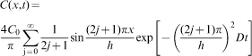
The solution to this problem, without any additional Cr source, can simply be written as the following infinite series17

 , which represents the overall Cr available in carbide form
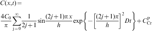
 is simply 0·012, i.e. the difference between the bulk Cr concentration and the matrix Cr concentration. Equation (3) may then be used, subject to the following conditions, to calculate the Cr concentration profiles at various temperatures:
if C(x,t) as calculated by equation (3) is greater than C 0, then the Cr contribution due carbide dissolution is not  ; the upper bound of C(x,t) is limited to C 0
after all the carbide particles have dissolved back, the  term vanishes.
The width of the carbide free layers, as well as the Cr concentration at the edge of these layers, was already known from the SEM-EDS analysis of the service exposed material. This information may be substituted in equation (3), and the same can be solved for obtaining the values of wall temperatures.
The values of these average effective temperatures may then be substituted back in equation (3) for determining the width of the carbide free layers at any given time. This information will be essential for the quantitative estimation of the loss in strength and remaining life.
Equation (3) has been used to calculate the Cr concentration profiles at various temperatures for 20 000 h of exposure time using the diffusivity data for Cr in γ-Fe.18 These profiles are presented in Fig. 4. Metallographic studies on the service exposed sample (20 000 h) show that the widths of the carbide free layers are 250 and 150 μm on the outer and inner surfaces respectively. The SEM-EDS analysis shows that the Cr concentration at the edge of these layers is 0·2 wt-%.
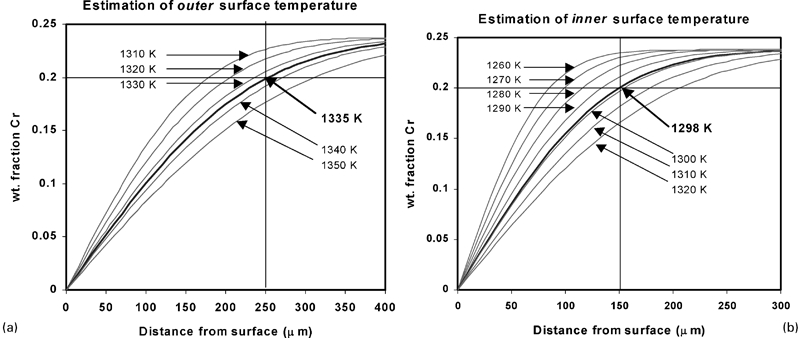
Chromium concentration profiles of process heater tube at various temperatures
Thus, at the outer surface (x is the distance from the outer surface)


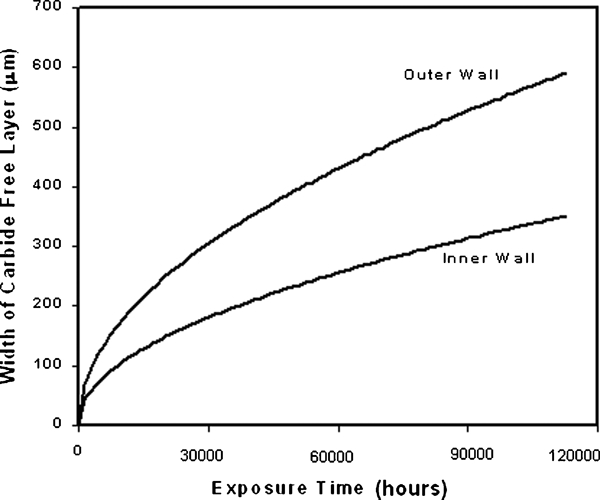
Growth kinetics of carbide free layers in Fe–Ni–Cr process heater tube
Conclusions
A modification of the classical diffusion problem, i.e. loss of material from both sides of a slab, is able to explain the kinetics of Cr depletion in the Fe–Ni–Cr alloy. The rate of Cr loss is almost twice as fast from the outer surface as compared with the inner surface due to the higher temperature experienced by the outer wall. This model would be useful to predict the chromium depletion at various times to prevent the catastrophic failure of the Fe–Ni–Cr austenitic steel process heater tube.
Footnotes
Acknowledgements
The authors are thankful to Dr A. Mitra and Mr A. Das, scientists of CSIR-National Metallurgical Laboratory, Jamshedpur, India, for discussion and suggestions.