
Abstract
A composite structure comprising high strength titanium (Ti) alloy core and a high surface area pure Ti coating can be ideal for implant applications. In this work, the corrosion behaviour of pure Ti coatings composed of porous top layer (∼100 μm) and dense bottom layer (∼500 μm) obtained by cold spray method has been investigated. The porous top layer satisfies the high surface area requirement for the implant and the dense bottom layer ensures a good corrosion protection of the substrate and also good bond strength. In order to further improve the corrosion and mechanical property of cold sprayed Ti coatings, heat treatment (850°C for 5 h) was applied. Electrochemical potentiodynamic and electrochemical impedance spectroscopy (EIS) measurements were used to characterise the electrochemical corrosion behaviour of the cold sprayed Ti coatings in Hanks’ solution. For comparison, the corrosion and mechanical properties of annealed and un-annealed wrought Ti substrates were also investigated. Our results showed that the as sprayed Ti coatings exhibited a relatively lower corrosion resistance than those for pure Ti substrate. However, post-spray heat treatment improved the corrosion resistance to a level close to that of the bulk material. Furthermore, EIS studies revealed that the newly formed dense and structurally stable oxide layer on the surface of the coating during potentiodynamic scanning was beneficial to the corrosion behaviour.
Keywords
Introduction
While selecting the material for medical implants, three major factors need to be considered: biocompatibility, osseointegration and mechanical strength.1 – 3 Corrosion resistance of an implant to body fluid can be improved by creating a corrosion resistant barrier layer on it.4 Furthermore, by creating a rough or porous layer on the implant, osseointegration can be enhanced due to increased surface area.5 Titanium alloys exhibit very good mechanical strength but relatively low corrosion resistance compared to pure titanium. For example, any dissolution of aluminium and vanadium ions from the commonly used Ti6Al4V alloy may result in toxicity effects.6 – 9 In order to combine good mechanical property of Ti6Al4V and good corrosion property of titanium, thermal spray methods (e.g. plasma spray) have been used to produce titanium barrier coatings on Ti6Al4V alloys.10 Although porous Ti coatings with high surface area can be achieved by plasma spray method,11 the elevated processing temperatures unless carried out under inert environment result in oxidation of Ti as well as associated thermal residual stress. Furthermore, plasma spray does not create a metallurgical bonding with the substrate. These effects can lead to degradation and detachment of Ti coatings from the metallic substrate. Cold spray, on the other hand, can be a suitable alternative and mitigate the fore mentioned problems associated with plasma spray. Since its first invention in middle 1980s, cold gas dynamic spray technique has rapidly found many applications in recent years.12 It differs from traditional thermal spray technique in that there is no need for heating the feedstock to be melted or semimelted before spraying. The feedstock particles are accelerated by high pressure gas of helium or nitrogen to supersonic speeds through a converging/diverging nozzle and then deposited on a substrate by plastic fusion at temperatures generally well below the melting point of the feedstock powder. 13 13,14 The low temperature processing environment reduces the oxide content in the deposits and avoids the undesirable phase change and thermally induced stress, which makes cold gas dynamic spray a very attractive technique for many applications. 15 15,16
Recent advances on cold sprayed Ti coatings include studies on fatigue behaviour by Price et al.,17 and influence of post-spray heat treatment on microstructure and mechanical properties carried out by Li et al. 15 18 15,18,19 Also, Hussain et al.20 studied the role of porosity on the corrosion behaviour in salt water of both free standing Ti deposits and coatings, while corrosion behaviour of the coatings in seawater has been investigated by Wang et al.21 However, most of these studies are focused on producing a dense coating to improve its corrosion property as a barrier layer. The potential applications of cold sprayed Ti coatings in biomedical applications have not received much attention so far.
In our previous work,22 cold sprayed Ti coatings composed of two distinct layers (a top porous layer with variable porosity and a dense bottom layer) have been successfully achieved. The objective of the present work is to study the in vitro corrosion behaviour of cold sprayed Ti coatings in Hanks’ solution and to evaluate their suitability for biomedical applications. The conventional potentiodynamic polarisation technique as well as electrochemical impedance spectroscopy has been used to test the electrochemical corrosion characteristics. In addition, post-spray heat treatment has been applied to modify the microstructure and other properties of cold sprayed coatings. The corrosion behaviour of oxide layer formed during potentiodynamic polarisation process was further studied by electrochemical impedance measurements. Also, the role of oxide layer as a potentially useful protective layer in biomedical applications is highlighted.
Experimental details
Deposition of coatings and heat treatment
Commercially available pure wrought titanium sheet (98·9%, Mcmaster-Carr Co., USA) was used as the substrate. Rectangular Ti coupons, 50×36×3 mm, cut from sheet materials, were grit blasted with Al2O3 particles (36 mesh) and ultrasonically cleaned in acetone for 10 min before cold spraying. The spray powder was commercial titanium sponge powder (Accushape Inc., USA) with 325 mesh size. A commercial cold spray (Kinetic 400 CGT, Germany) as well as an in-house developed system was utilised to fabricate Ti coatings under optimised spray parameters listed in Table 1. Coating thickness for all samples was ∼600 μm. The basic schemes of the cold spray process and other information are described in the literature.12,23 – 30 After spraying, some samples were annealed at 850°C for 5 h in Argon with 5% hydrogen atmosphere. The pure wrought Ti coupons were also annealed under same conditions for comparison.
Cold spray deposition parameters
Microstructural characterisation and microhardness studies
The characteristics of powders and cross-sections of coatings were examined using an optical microscope (Nikon Eclipse LV100) as well as a scanning electron microscope (HITACHI S-2600N SEM). The coatings were cut perpendicular to the coating/substrate interface, hot mounted, and then polished progressively (down to 1200 SiC paper grit). The final polishing procedure was performed using colloidal silica with a particle size of 0·04 μm. The samples were washed in running water and ultrasonically cleaned with acetone. The samples were etched by swabbing the samples with an etchant of 91% H2O, 3% HF and 6% HNO3. The phase composition of coatings was determined by a RIGAKU MINIFLEX XRD system using Cu Kα. The X-ray data were collected in the 2θ range of 30-90° in steps of 0·02°. A Future-Tech, type FM microhardness tester was used to measure microhardness. The microhardness measurements were performed on the cross-section of the sprayed deposit with a load of 100 gf applied for a dwell time of 10 s.
Electrochemical corrosion studies
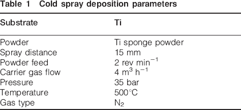
The electrochemical measurements were carried out using a flat three-electrode cell (K0235 flat cell, Princeton Applied Research, Fig. 1), with the samples acting as the working electrode, a silver/silver chloride electrode as the reference electrode and a platinum grid as the counter electrode. The specimen area exposed to the electrolyte solution was 1 cm2. A commercially available simulated body fluid solution (SBF), Hanks’ balanced salt solution with pH = 7·25±0·15 [composition, NaCl: 8 g L−1, KCl: 0·4 g L−1, NaHCO3: 0·35 g L−1, Na2HPO4 (anhydrous): 0·0477 g L−1, KH2PO4: 0·06 g L−1 and D-Glucose: 1 g L−1 was used as the electrolyte solution.
Exploded view of model K0235 flat cell
Potentiodynamic polarisation curves were determined by using a Solartron SI 1287 potentiostat and electrochemical impedance spectra were recorded with a Solartron 1255B frequency response analyser. Prior to each measurement, all samples (as sprayed Ti coatings, annealed Ti coatings, pure Ti substrates and annealed pure Ti substrates) were polished progressively until a mirror finish surface was achieved. In order to avoid the possible oxidation of samples, the electrochemical tests were commenced immediately after immersion of the samples in Hanks’ solution. All the experiments were carried out at least three times under ambient temperature.
For potentiodynamic polarisation studies, the working electrodes were polarised from −1 V(vs reference electrode potential) to +5 V at a scan rate of 1 mV s−1. CorrWare software was used to determine the corrosion potential (E corr), corrosion current (I corr) and polarisation resistance (R p). For electrochemical impedance spectroscopy, measurements were conducted at open circuit potential (OCP), with the amplitude of sinusoidal signal set at 10 mV. The range of measured frequency extended from 0·01 Hz to 10 kHz, with a logarithmic sweep of six points per decade. The impedance data at higher frequency range were not recorded due to artifacts that become significant beyond 10 kHz in a low conductive solution like the SBF.31 However, one can ignore the high frequency artifacts in constructing the equivalent circuit without changing the surface film parameters considerably. This issue will be discussed further, later in this paper. The recorded impedance spectra were fitted using the complex nonlinear least square method which was developed by Boukamp,32 with the aid of Zview software. After polarisation, the electrochemical impedance spectroscopy studies were also conducted again to investigate the possible characteristic changes of the sample surface. This was done following a delay period of one hour in order to stabilise the OCP.
Results and discussion
Microstructural characterisation
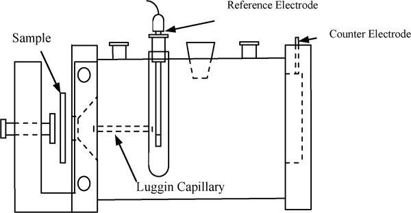
The typical morphology of titanium sponge powder used for deposition of coatings in this paper is shown in Fig. 2. Two different shapes of particles are visible; relatively large elongated particles mixed with porous spongy clusters formed by small particles (Fig. 2a). In order to study the internal structure of the particles, the Ti sponge powder was hot mounted, polished and etched, and the structure is shown in Fig. 2b. Although the biggest elongated particles have a size close to 100 μm and the small ones have a size in a range of 10-30 μm. Structurally, the two types of particles are essentially same, i.e. both have an internal porous structure with pore size ∼1·5 μm.
Images (SEM) of Ti sponge powder for a surface image and b cross-section image
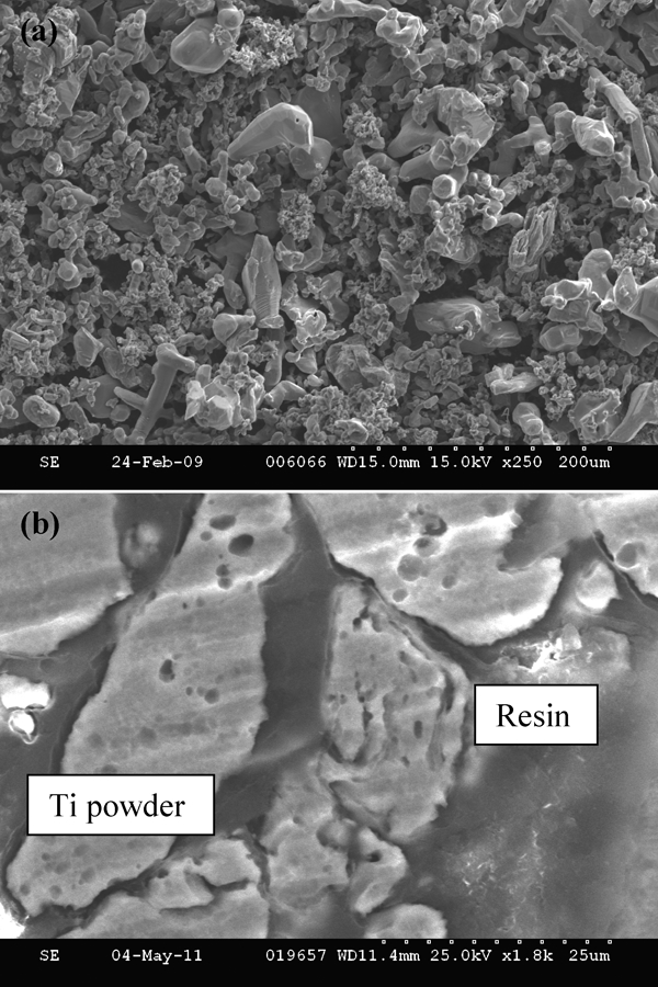
In our earlier study,22 we have demonstrated the influence of particle morphology on the resulting cold sprayed coating structures. The above mentioned sponge powder provides a great flexibility in terms of controlling the coating structures, i.e. very dense to porous. Examining the coating structure shown in Fig. 3a, it is observed that the top surface layer of the coating is relatively porous compared to the bottom layer. Both porous top layer and the internal porous structure of sponge powder can provide the anchoring sites and thus enhance osseointegration. Dense bottom layer ensures a good bonding between the coating and the substrate. The optimal porosity for tissue integration has not been determined yet in the literature. However, too large porosity may adversely affect the cell growth between the implant and the bone. The cold sprayed Ti coating with small porosity on top layer might be a potential candidate for biomedical applications.
Cross-section SEM images showing a overall morphology of as sprayed Ti coating, b detailed morphology of etched Ti coating and c detailed morphology of annealed and etched Ti coating
The detailed morphology of as sprayed Ti coating after etching is shown in Fig. 3b. The splat structure of sprayed coatings resembles the initial particle shapes. This is in spite of the fact that titanium sponge powder experienced significant deformation during cold spray process. Although mechanical interlocking of particle to particle is apparent in the coating, metallurgical bonding was also observed at some particle/particle interfaces and particle/substrate interfaces (marked by the arrows) due to cold welding phenomenon. Some incomplete interfacial fusion and submicron pores are visible in the etched surface. The incomplete interfacial defects resulted from the attack of particle boundaries by the etchant20 and the submicron pores resembled the internal porous structure of sponge powder.
Figure 3c shows the detailed morphology of annealed and etched Ti coating. After annealing, it was found that some contact interfaces between the deposited particles, interfaces between particles and substrate disappeared through the atomic diffusion and grain boundary migration (marked by arrow in Fig. 3c). The metallurgical bonding to the substrate improved further after annealing. A higher bonding strength can be anticipated due to these changes. It was also observed that big pores and cracks in Fig. 3b were converted into smaller ones in Fig. 3c during the annealing process. It is to be noted that the cold sprayed coating is highly strained due to the inherent mechanical deformation associated with the process. A better corrosion behaviour could results from strain relief induced by the annealing process. The optical microscope images of Ti substrate, as sprayed Ti coating and heat treated Ti coating were shown in Fig. 4. Comparing Fig. 4a and b, it is found that fine grains were observed in the coating microstructure after the annealing step. This observation indicates that the material experienced nucleation and recrystallisation during the annealing process and improved metallurgical bonding between deposited particles was obtained.18 However, unlike the bulk material (Fig. 4c), grains do not grow thoroughly and grain boundary is not well defined at some places of the coating. This is possibly related to the pre-existing surface oxide layers in the as received powder, which prevent the grain growth. In other words, some level porosity still can be maintained in the coating even after the strain relief annealing step.
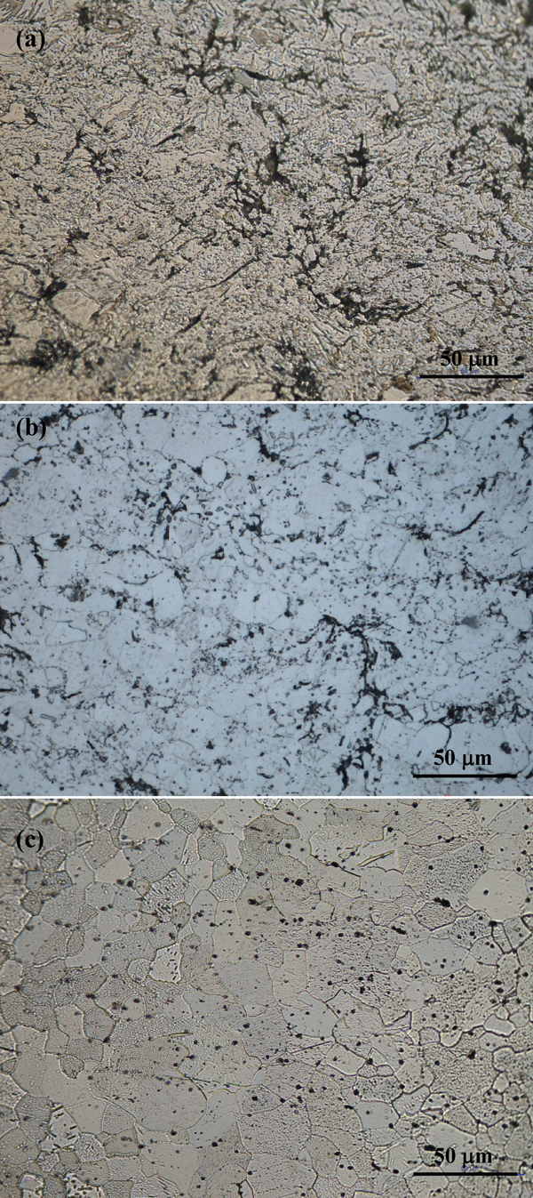
Cross-section optical microscope images of a etched pure Ti substrate, b etched Ti coating and c annealed and etched Ti coating at 850°C for 5 h
Phase analysis
The X-ray diffraction patterns of the powder, as sprayed specimen and heat treated specimen are shown in Fig. 5. No major difference in the XRD patterns was expected as the coating formation primarily relies on cold plastic deformation of the particles and interfacial fusion. After annealing step, no evidence of new phase formation, for example titanium oxides, was found. Compared to atmospheric plasma sprayed coating, less oxide content are beneficial to the mechanical strength of the coatings.
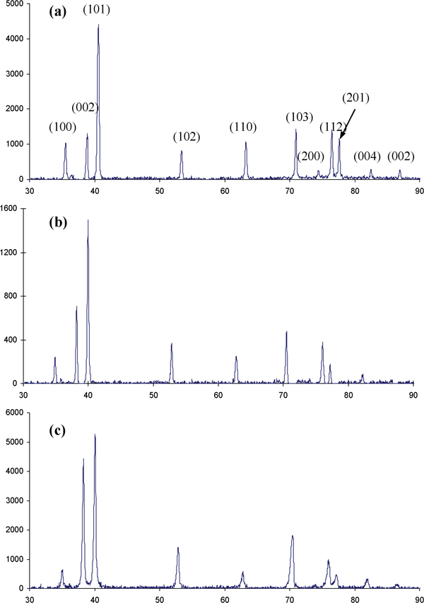
X-ray diffraction patterns of a Ti powder, b as sprayed Ti coating and c annealed Ti coatings
Microhardness analysis
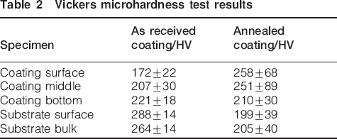
Table 2 shows the Vickers microhardness values measured on as sprayed and annealed titanium coatings and the corresponding values on the bulk substrate. For Vickers indentation tests, strong load–hardness dependence has been found in metallic coatings.14 When a relatively lower load is used, the indentation location, whether in the bulk of a splat or at a splat boundary, affects the final results considerably.14 This explains why big standard deviation values were found in our coatings. Maximum values correspond to tests that happened in the bulk of a splat and minimum values may correspond to boundary regions. For as sprayed coatings, the microhardness values increased gradually from coating surface to the bottom. This is possibly due to the fact that the coatings became denser from surface to bottom. After the heat treatment, this trend disappeared, the microhardness of the coatings improved and the highest value (258 HV) on coating surface was found close to the value (264 HV) of bulk substrate. This is because nucleation and recrystallisation resulted in homogenous coatings. For pure titanium substrate, the microhardness on the surface (288 HV) is higher than in bulk, which is attributed to cold work hardening effect during the deposition. After annealing, the microhardness value is reduced to ∼200 HV, which is due to the release of residual stress. Similar results can be found in the literature.12 Cold sprayed coatings are reported to have higher hardness than wrought materials; 14 18 14,18,33 however, in our case the hardness of the coatings was much lower than that of the wrought material (substrate). This is because sponge titanium powder was used in this study and inter particulate defects are embedded by the cold deformation. After annealing, the hardness of coatings was improved and the highest value (258 HV) is close to the value (264 HV) for bulk substrate, which in turn indicates a homogenous coating was produced by the heat treatment.
Vickers microhardness test results
Microstructurally, porosity and residual stress are two major differences between cold sprayed coating and bulk material. These two parameters affect not only corrosion property but also mechanical properties. Although the residual stresses are eliminated by the annealing process, porosity of coatings was not completely eliminated as stated previously.
Potentiodynamic polarisation
Figure 6 presents the typical potentiodynamic polarisation behaviour of pure Ti, annealed Ti, cold sprayed Ti coating and the annealed coating. From the polarisation curves, it is evident that all four kinds of samples exhibit highly passive characteristics. The passive current density for as sprayed Ti coating is relatively higher than that of three other samples, but it is still lower than 8×10⁻⁴ A cm−2 even at anodic potential of 5 V. The average corrosion potential estimated from these curves are −376, −326 and −362 mV for annealed Ti coating, pure Ti substrate and annealed Ti substrate respectively, which are all approximately similar. However, the as sprayed Ti coating has a relatively lower corrosion potential compared to the other three, which is −445 mV. This indicates that the as sprayed Ti coating corrodes easily compared to others.
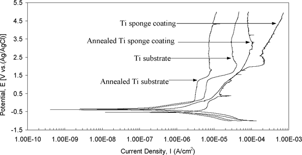
Potentiodynamic polarisation curves recorded for annealed and non-annealed Ti substrate and cold sprayed Ti coatings in Hanks’ solution. Scanning rate was 1 mV s−1
From the corrosion potential (−0·326 V) till 0·2 V, the current density for pure Ti substrate started around 2×10⁻⁸ A cm−2 and initially increased rapidly, and then resumed a slower growth at approximately 5×10⁻⁶ A cm−2. This characteristic behaviour suggests that the protective passive film formed in this potential range.33 From potential above 1·2 V, the current density further increased at a faster rate to a maximum value of 4×10⁻⁵ A cm−2 (obtained at ∼2·0 V), and then decreased slightly afterward, stabilising at a current density of ∼4×10⁻⁵ A cm−2. This behaviour suggests that the protective passive film formed previously was gradually replaced by a new protective passive film.34 The potentiodynamic polarisation curve for annealed Ti substrate has similar shape as that for the non-annealed one, but the current density is smaller than that of the non-annealed sample and stabilised at ∼1×10⁻⁵ A cm−2. This observation i.e. the corrosion property of wrought Ti improved by annealing process illustrates the effect of residual stress relief.
The polarisation curves for the Ti coatings are considerably different from the substrate samples. In the case of the as sprayed Ti coating, from the corrosion potential (−0·445 V) to about −0·3 V, the current density increased linearly from about 3×10⁻⁶ to 6×10⁻⁶ A cm−2, and then resumed a slower increase until 0 V. In the anodic regime, the current density increased continuously and reached a maximum value of 7×10⁻⁴ A cm−2 at the end of the scanning potential range (5 V). During this process, a current oscillation is seen at a potential ∼0·4 V, which typifies a pitting nucleation and repassivation process. At a potential around 2 V, severe pitting corrosion was observed, which leads to a big fluctuation for current density. It is to be noted that the existing pores on the surface may extend as pits into the sample. For the annealed Ti coating, a current density in the range of 4×10⁻⁷ to 1×10⁻⁶ A cm−2 was estimated in the potential range of corrosion potential to about −0·3 V. The current density increased continuously until ∼3·5 V, at which it stabilised at a value of 8×10⁻⁵ A cm−2.
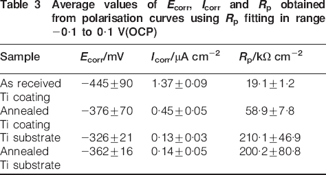
The average values of E corr, I corr and R p, from polarisation curves determined by the Zview software are presented in Table 3. The range of potential used for R p fitting is from −0·1 to 0·1 V(OCP). Note that the corrosion rates of uncoated samples are lower than those of coated samples and the lower corrosion potential observed in Table 3 for as sprayed Ti coatings also implies that the coated samples are less stable than the other three samples.
Average values of E corr, I corr and R p obtained from polarisation curves using R p fitting in range −0·1 to 0·1 V(OCP)
Comparing four polarisation curves in Fig. 6, it is apparent that heat treatment process improved the corrosion characteristics of samples. For Ti coating, the overall polarisation curve moved leftward after heat treatment and no obvious pitting behaviour was observed. And at high potential (above 3·5 V), current density of annealed coating exhibited a stable and passive behaviour compared to non-annealed sample. For Ti substrate, heat treatment made the polarisation curve move to low current density too. Moreover, the decrease in corrosion current (Table 3, from 1·37 to 0·45 μA cm−2) and the increase in corrosion potential (from −445 to −376 mV) on coating sample do indicate that the heat treatment can significantly improve the corrosion characteristics of cold sprayed Ti coating. The substantial improvements of corrosion characteristics are related to the strain relief as well as defect annihilation that occur during the annealing process. It is to be noted that substantial plastic deformation of the material is an inherent phenomenon in cold spray process. The annealing process causes recovery, recrystallisation and grain growth in this cold worked material. The observed reduction in discontinuity and porosity is a direct result of these phenomena. All these factors are expected to contribute towards the reduction in the corrosion rate.20
To demonstrate the repeatability of results, three measurements are shown for each case. Figure 7 Figures 7 and 8 present the results for Ti coatings and annealed Ti coatings respectively. The three measurement curves have similar shape and similar value. The pitting corrosion phenomenon occurred at ∼2·5 V for all three measurements (Fig. 7) and, it was not observed after annealing (Fig. 8). The current densities became stable when the potential was increased above 3·5 V for all three measurements compared to non-annealed samples. All these observations indicate a good repeatability of our experiments.
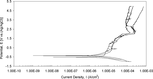
Potentiodynamic polarisation curves recorded for three cold sprayed Ti coatings in Hanks’ solution. Scanning rate was 1 mV s−1
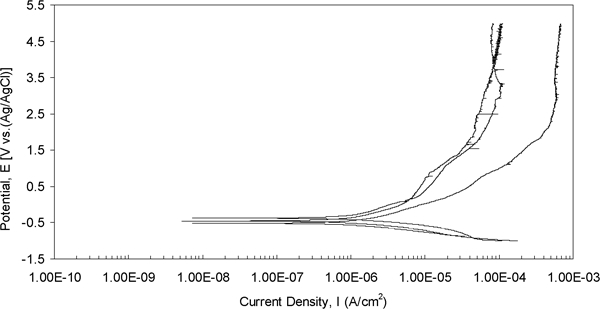
Potentiodynamic polarisation curves recorded for three annealed cold sprayed Ti coatings in Hanks’ solution. Scanning rate was 1 mV s−1
After the polarisation studies, the Ti coating samples were examined by the SEM. Figure 9a shows a typical view of pit morphology and Fig. 9b shows the magnified view. As observed in Fig. 9a, pits seem to have started from a local defect (void) and propagate along the interface of particles with different rates in different directions. Van Boven et al.35 have noted that pits preferentially occur in areas where the tensile residual stresses are high. A newly formed passive layer can be observed under higher magnification, as illustrated in Fig. 9b. Detailed investigations indicated that the passive layer consists of two types of morphologies: the particles with spherical shape (as shown by arrows) embedded in shell shaped films. Phosphates of calcium are usually formed on titanium and its alloys when immersed in Hanks’ solution.36 The existence of phosphorus without calcium in the spherical particles detected by energy dispersive X-ray spectroscopy analysis indicates that the spherical particles might be titanium phosphate precipitated on the surface of Ti oxide film. A detailed examination of formation mechanism of newly formed layer needs further attention.
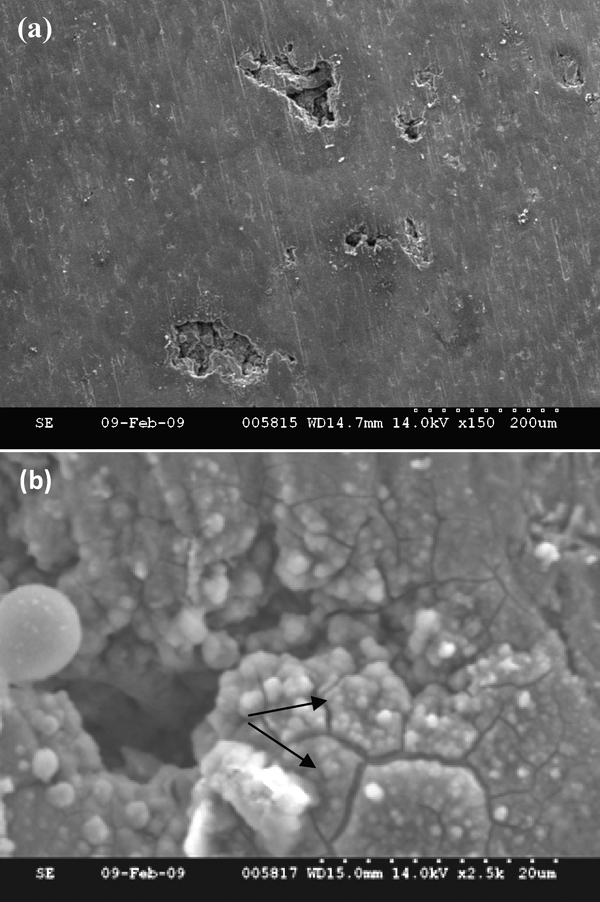
Images (SEM) showing characteristic morphologies of pitting generated on as sprayed coating surface during polarisation process: a overall surface view and b high magnification view showing newly formed layer
Electrochemical impedance spectroscopy
The representative electrochemical impedance spectra obtained prior to polarisation together with the fitted curves are shown in Fig. 10. After potentiodynamic polarisation test and one hour waiting for a stable OCP, the EIS tests were performed again and the results are shown in Fig. 11. Figure 12 shows the equivalent circuits used for simulating the spectra obtained from different samples at various conditions. The quality of fitting to the equivalent circuit was judged by the Chi-squared values (χ 2) given in Table 4, which confirmed a very good agreement between the fitted and experimental data.
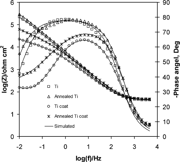
Experimental and fitted Bode plots for four kinds of samples of (before polarisation test) Ti, annealed Ti, Ti coating and annealed Ti coating in Hanks’ solution
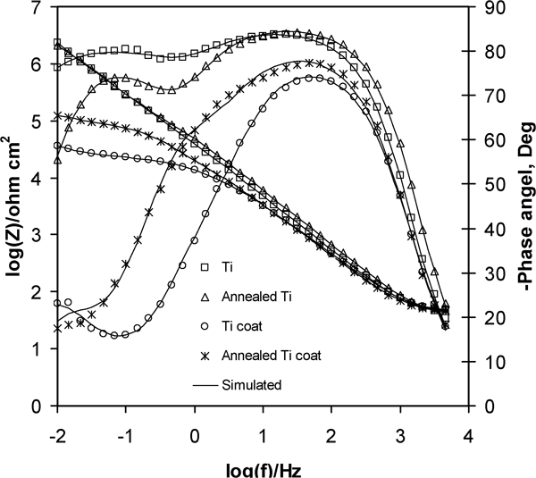
Experimental and fitted Bode plots for four kinds of samples, (after polarisation test) Ti, annealed Ti, Ti coating and annealed Ti coating in Hanks’ solution
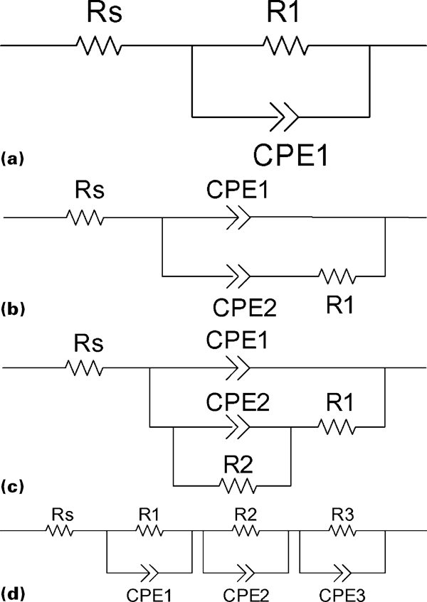
Electrochemical equivalent circuits used for interpretation of measured impedance spectra
EIS spectra fitting results obtained from experimental impedance data using electrochemical equivalent circuits of Fig. 12
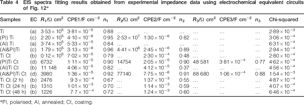
*Pl, polarised; Al, annealed; Ct, coating.
In our earlier study,31 we investigated the influence of electrochemical cell design and solution conductivity on high frequency artifacts. We demonstrated that the high frequency artifacts are unavoidable in SBF. However, with K0235 flat cell combined with Hanks’ solution, one can ignore the high frequency artifacts when equivalent circuit method is used to analyse impedance spectra data. The values of equivalent circuit elements would not change much by deleting the high frequency artifacts and a meaningful electrolyte resistance is obtained when the high-frequency limit is set ∼10 kHz.
From Fig. 10, it is clear that one time constant behaviour controlled the corrosion mechanism for Ti substrate samples. The impedance data are simulated by a single layer equivalent circuit (Fig. 12a) using Zview software, in which R s refers to solution resistance, constant phase element (CPE1) corresponds to the double-layer capacitance and R 1 is the charge transfer resistance. Here, constant phase element (CPE) was used to substitute the pure capacitance, which accounts for deviations from ideal dielectric behaviour related to interface roughness and inhomogeneity. 37 37,39 A similar result can be found for annealed Ti sample with only a little increase in impedance modulus at the lowest frequency range. The equivalent circuit was also used by other literature reports 3 40 3,40,41 to explain the corrosion mechanism in case of single passive oxide layer present on the metal surface in SBF solution.
The impedance spectra displayed in Fig. 10 for as sprayed Ti coating as well as annealed Ti coating exhibit a two time constant characteristics. A modified double-layer equivalent circuit (Fig. 12b) can be satisfactorily used for fitting the spectra obtained from Ti coated samples before and after the anneal process. In this case, the first time constant (CPE1) in high frequency range represents the impendence characteristics of outer porous passive layer formed by spontaneous oxidation of Ti. The second time constant (CPE2) in low frequency range represents the impedance characteristics of cold sprayed Ti coating layer. Considering the bottom layer of cold sprayed Ti coating is relatively dense, it is can be anticipated that CPE2 represents the porous top layer of the coating. R 1 is the charge transfer resistance of the outer passive oxide layer.
The impedance modulus at the lowest frequency for coated Ti sample is around 1·1×104 Ω cm2, which is lower than the uncoated sample and the highest phase angle is about −60°, which is far away from −90°. This indicates a relatively poor corrosion protection property for the coated samples and this agrees well with the results obtained from potentiodynamic polarisation tests. However, after heat treatment, the corrosion property was remarkably enhanced with the increase in the impedance modulus at the lowest frequency to 5×10⁴ Ω cm2 and the highest phase angle increased to −70°. This indicates cold sprayed Ti coating became denser and more homogenous by annealing process, which is beneficial to the corrosion protection. This observation is in line with the CPE2 value being reduced by one order of magnitude (seen in Table 4), through the annealing process. These results from EIS tests are consistent with the outcome from potentiodynamic polarisation tests and indicate that the corrosion characteristics of sprayed coating were greatly improved by post-heat treatment process. In addition, the missing of R 2 in the modified equivalent circuit, which is a slightly different form of traditional double-layer equivalent circuit, is due to the fact that the porosity of coating under study is small and has high conductivity.
After potentiodynamic polarisation test, a two peak EIS curve (Fig. 11) is observed for Ti substrate samples, which revealed that a two time constant behaviour controlled the corrosion mechanism and a new oxide layer was formed by the polarisation process. A conventional double-layer model equivalent circuit (Fig. 12c) is satisfactorily used to fit the spectra obtained from Ti substrate samples in polarised state. This circuit is slightly different from the modified circuit (Fig. 12b), in terms of addition of the resistance R 2 to represent the transfer resistance of the newly formed oxide layer. EIS spectra obtained from Ti coatings and annealed Ti coatings after polarisation test are satisfactorily simulated by the equivalent circuit based on a three-layer model (inner sprayed Ti coating, outer oxide layer and the newly formed layer, seen in Fig. 12d). Similar three-layer model was also used by Wang et al.37 to simulate the nucleation and growth of apatite on chemically treated titanium alloy.
The impedance results in Fig. 11 show that after polarisation test, a new layer was formed on the surface of substrate as well as coated samples. However, close scrutiny of each of the polarised samples under SEM revealed that this newly formed layer could only be observed in the area near the pits on the coated Ti surface. This is probably because, around the pits, the newly formed layer cracked and formed a shell like morphology (seen in Fig. 9b). The energy dispersive X-ray spectroscopy analysis indicates that the newly formed layer is Ti oxide layer. Also, titanium phosphate precipitated on Ti oxide layer (Fig. 9b) results in the appearance of third CPE in the EIS model (Fig. 12). In order to better understand the electrochemical phenomena taking place at the interface of biomaterial/cold sprayed Ti coating/Hanks’ solution, two physical models were constructed and shown in Fig. 13. Figure 13a represents the double-layer model for cold sprayed Ti coating before polarisation, which corresponds to the equivalent circuit of Fig. 12b. Figure 13b represents the three-layer model for cold sprayed Ti coating after polarisation. Different with Fig. 13a, a newly formed TiO2 layer was presented on the top surface.
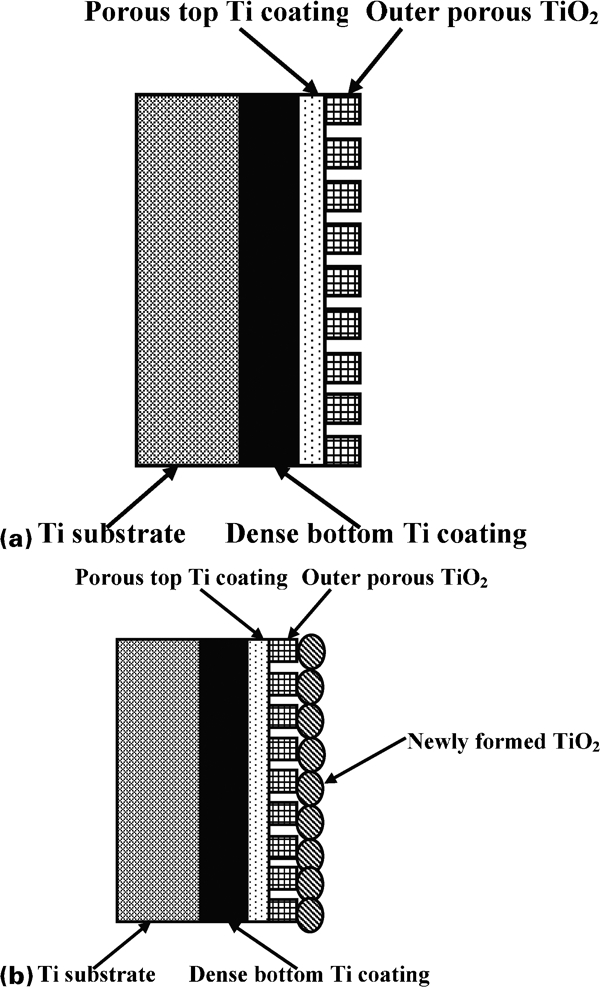
Physical model of biomaterial/Ti coating/Hanks’ solution interface
After comparing the EIS data of Ti substrate before and after the polarisation tests, it can be found that the impedance modulus at the lowest frequency increased from 2×10⁵ to 2×10⁶ Ω cm2, and the two phase angles at peak points are both close to −90°. This suggested that the newly formed oxide layer was beneficial to corrosion protection of the coatings. In addition, from Table 4, it is obvious that the newly formed oxide layer acts as an ideal capacitor (with n value close to 1), which in turn indicates an improved corrosion property for the material.
Further EIS measurements were carried out at 2, 24 and 48 h for Ti coating immersed in Hanks’ solution and the results are presented in Fig. 14. The impedance modulus decreased drastically at the beginning of 2 h of immersion, the value at lowest frequency dropped from 1·1×104 to 1·2×103 Ω cm2. However, after 2 h there was no significant change in impedance modulus. At low frequency, the phase angle was reduced from −30° to −40° with an immersion time of 2 h. When the immersion time was increased to 24 h, the phase angle was reduced further to −50°. At middle frequency, the phase angle was shifted to −50° with an increase in immersion time.
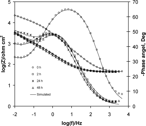
Experimental and fitted Bode plots for Ti coatings with immersion time of 0, 2, 24 and 48 h in Hanks’ solution
The immediate decrease in impedance value and increase in phase angle at middle frequency for 2 h of immersion both indicated a decrease in corrosion resistance of outer passive layer formed by spontaneous oxidation of Ti. This was also suggested by the decrease in R 1 value with the increase in immersion time (Table 4). The unchanged nature of Bode plot for 24 and 48 h immersion indicated that a stable and passive oxide film formed.
Conclusions
Pure titanium coatings composed with porous top layer and dense bottom layer were successfully deposited by cold spray method. Porosity and residual stress are two major characteristics for cold sprayed coatings, which affect their mechanical and corrosion properties. Our results show a good correspondence between these two characteristics and coating properties. The results also showed that post-deposition heat treatment, carried out at 850°C for 5 h, drastically improved the microhardness and corrosion characteristics for the coatings. The heat treated Ti coatings showed microhardness and corrosion resistance values close to those for Ti substrates. This is because that the material experienced nucleation and recrystallisation during the annealing step. The residual stresses were relieved and the interconnected porosity was reduced because of atomic diffusion.20 The potentiodynamic polarisation tests were carried out until high voltage (5 V) to form a passive Ti oxide layer. The newly formed layer examined by EIS method revealed that it is beneficial to the improvement of corrosion behaviour. The EIS results also indicated that a stable and passive film already formed on surface of Ti coating after immersion of 24 h in Hanks’ solution and further immersion would not change its corrosion property much. In addition, the second time constant element present in the impedance diagram for coated samples can be used to determine the electrochemical characteristic of porous top layer of the coatings.
Footnotes
Acknowledgements
The authors gratefully acknowledge financial assistance from the Naval Health Science Laboratory, under contract no. W911QY-09-C-0011. The authors would like to thank late Mr Abhinav Chaudhari, Dr J. Karthikeyan (ASB Industries for facilitating the initial experiments) and Dr B. C. Satishkumar for helpful discussions.