
Abstract
The galvanic corrosion behaviours of carbon fibre composite coupled to aluminium are studied when the galvanic couple is just immersed in artificial seawater or connected to a closed electric circuit. The effects of grinding condition, concentration of artificial seawater, applied torque, applied current and experimental time are studied. The roughness average, weight gain of carbon fibre composite and weight loss of aluminium are investigated as a function of the above variables. The results show that the applied current can accelerate the galvanic corrosion greatly. With improving grinding condition and increasing applied torque, the roughness average, weight gain of carbon fibre specimen and weight loss of aluminium specimen increase, reach maximum and then decrease. With increasing concentration of artificial seawater, applied current and experimental time, these measured values increase. Corroded surface morphology is also investigated using scanning electron microscopy.
Introduction
Composite materials are increasingly being utilised in marine application over the past few decades due to their light weight and good specific strength. These materials are now being applied for composite pressure vessel for subsea blowout preventer,1 autonomous underwater vehicle2,3 and even offshore oil equipment. 4 4,5 However, when composite materials are connected to metals, such as aluminium and steel, galvanic corrosion occurs at the interface of composite materials and metals. Not only the metal but also the composite materials are corroded, which causes degradation of composite structures.
In recent years, the galvanic corrosion behaviours of composite materials coupled to various metals in different aqueous medium are researched. Fovet et al.6 studied the electrochemical behaviour of carbon fibre posts in an artificial saliva gal Fovet medium for comparison with that observed for different alloys (gold, NiCr and amalgams) in the same medium and accessed the coupling that might occur between these posts and alloys. The results showed that posts might be involved in galvanic coupling in the presence of oxygen. Bozzini and Fanigliulo7 studied the galvanic corrosion of carbon steel coupled to carbon fibres in acid sulphate, near neutral chloride and bicarbonate solutions using various electrochemical measurements. They found that the galvanic coupling between carbon steel and carbon fibres gave rise to the galvanic corrosion of steel. Mueller et al.8 investigated the coupling effects of gold anodised titanium, stainless steel for biomedical applications, carbon fibre reinforced polyetheretherketone (CFRP) and CFRP containing tantalum fibres using electrochemical and long term immersion experiments in simulated body fluid. They found an active dissolution behaviour of both CFRPs, which leads to delaminating the carbon fibres from the matrix. Tavakkolizadeh and Saadatmanesh9 studied the galvanic corrosion of carbon and steel in two simulated aggressive environments using potentiodynamic polarisation and galvanic corrosion tests. The results showed the existence of galvanic corrosion; however, the rate of such corrosion could be decreased significantly by epoxy coating. Gebhard et al.10,11 studied the galvanic corrosion of polyacrylnitrile and pitch based short carbon fibres in polyetheretherketone composites coupled to stainless steel. The results showed that polyacrylnitrile based fibres have a higher corrosion resistance than pitch based ones. Bellucci12,13 studied the effects of dissimilar metal and temperature, area ratio and environmental degradation of galvanic corrosion between non-metallic composites and metals.
In addition, galvanic corrosion of carbon fibres and metal in various metal matrix composites is also researched widely. Orth and Wheat14 studied the corrosion behaviour of particulate reinforced graphite/copper metal matrix composites in 3·5 wt-% sodium chloride solution. They found that all the composite samples exhibited uniform corrosion and localised galvanic corrosion at the graphite/copper interface. Copper was oxidised and went into solution, and a small amount of graphite was detected in the electrolyte due to galvanic corrosion. Bakkar and Neubert15 studied the corrosion behaviour of carbon fibre reinforced magnesium metal matrix composite with emphasis on the galvanic corrosion arisen between the magnesium matrix alloy and the carbon fires. The susceptibility of carbon/magnesium interface to degradation was also ascertained. The galvanic corrosion studies on aluminium reinforced with uncoated and coated carbon fibres were also investigated, and the corrosion mechanisms at the carbon/aluminium interface were analysed.16,17
The present work aims to investigate the effects of grinding condition, concentration of artificial seawater, applied torque, applied current and experimental time on the galvanic corrosion behaviour of carbon fibre composite coupled to aluminium. The experimental galvanic couples with and without closed electric circuit (CEC) are used respectively. The roughness average, weight gain of carbon fibre composite and weight loss of aluminium are investigated as a function of the above variables.
Experimental
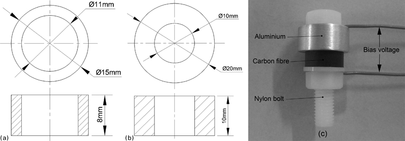
The carbon fibre specimens (see Fig. 1a) were cut from carbon fibre composite tubes, which are manufactured by a winding process using carbon–epoxy prepreg tape (T700 carbon fibre and E51 Bisphenol-A epoxy resin). The carbon fibre composite tube is composed of 10 anisotropic plies with 90° winding angle and 10 anisotropic plies with 0° winding angle with respect to the axis of the tube. The thickness of each ply is 0·1 mm. These fibres have an average diameter of 7 μm. The aluminium specimens were made of AISI 2124 aluminium. The dimensions are shown in Fig. 1b.
Experimental specimen for galvanic corrosion
The galvanic couple, including a carbon fibre specimen and an aluminium specimen, was abraded with the same wet abrasive paper of 500, 1000, 1500, 2000, 2500 or 3000 grit, degreased with acetone followed by alcohol in an ultrasonic bath for 3 min and then air dried. The specimen assembly, as shown in Fig. 1c, was tightened with a nylon bolt, nut and washer using a torque wrench.18 Different torques from 0·1 to 0·9 N m were applied.
Before the immersion tests, the galvanic potential and galvanic current of the galvanic couple were monitored in 3·5% artificial seawater. The carbon fibre and aluminium specimens were abraded with same wet abrasive paper of 1000, and the test equipment was installed according to the standard guide of ASTM G71-81.19 A galvanic corrosion monitor (Kesite, CST500, China) was used to measure the electrochemical parameters.
Two kinds of experimental set-ups are adopted for immersion tests, that is, the galvanic couples with and without CEC. For the couple without CEC, it was just immersed in artificial seawater for testing. For the couple with CEC, electrical connection to the specimens was established via an isolated copper wire. It is considered that under certain conditions, an electrical current that transgresses the interface of carbon fibre and stainless steel causes extensive galvanic corrosion of the carbon fibre. The electrical current is the main reason for fibre corrosion in galvanic corrosion behaviour.10,11 Therefore, in this work, the carbon fibre specimen was connected to the anodic outlet of 5 V dc power supply using an attached wire. The aluminium specimen was connected to the cathodic outlet of the power supply. A slide resistor was connected to the CEC in order to achieve different current, such as 30, 60 and 90 mA. The experiments were performed for different times. For the couple without CEC, it was performed for 2, 6 and 10 days respectively. For the couple with CEC, it was performed for 8, 12 and 24 h respectively.
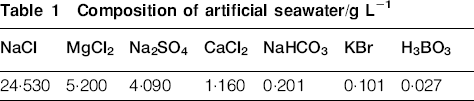
The galvanic corrosion tests were performed in artificial seawater prepared with deionised water and sea salts; the detailed composition of the solution is given in Table 1.20 The concentration of the artificial seawater is considered as 3·5%. In addition, the deionised water and artificial seawater with the concentration of 7·0% are also used for comparison. For the 7·0% artificial seawater, double sea salts were used. In this study, tests were conducted at 60°C to accelerate galvanic corrosion. After the tests, the carbon fibre and aluminium specimens were cleaned with deionised water in an ultrasonic bath for 3 min in order to remove the corrosion products. Then, the aluminium specimens were air dried, whereas the carbon fibre specimens were dried in a drying baker for 1 h at 80°C to remove the absorbed water.
Composition of artificial seawater/g L−1
After the galvanic corrosion experiments, the roughness average of the corrosion surface was measured with a surface roughness tester (TimeSurf TR300, China), and the weights of carbon fibre and aluminium specimens were measured using an electronic balance (Sartorius BSA224S, Germany). The roughness average was measured five times for each of the three specimens; therefore, the total roughness average was the average of 15 roughness averages. The weight change of the specimen was the average of three experimental runs. The corroded carbon fibre and aluminium specimens were sputter coated with gold in ion sputter (Hitachi E-1010, Japan), and corrosion morphology examination was performed by scanning electron microscopy (SEM, Hitachi S-4800, Japan).
Results and discussion
Electrochemical measurements
The previous work shows that for the coupled specimens, galvanic corrosion dominates the corrosion behaviour, whereas crevice corrosion plays a less important role, due to the fact that a high potential difference exists between the carbon fibre and aluminium specimens. Therefore, the crevice corrosion can be neglected in the work.
The measured galvanic potential and galvanic current of the galvanic couple in 3·5% artificial seawater are shown in Fig. 2. It can be seen that the galvanic potential decreases from −410 mV and becomes stable at ˜−480 mV in the 7th day. The galvanic current increases rapidly in the first 4 days and becomes stable at ∼100 μA later. The results show that the galvanic corrosion occurs continuously.
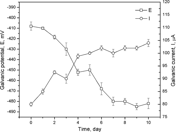
Measured galvanic potential and galvanic current in 3·5% artificial seawater
Effects of grinding condition and concentration for galvanic couples without CEC
The measured roughness average and weight change of the carbon fibre and aluminium specimens for the galvanic couples without CEC are shown in Fig. 3. It can be seen from Fig. 3a and b that with the improving grinding condition (increasing of grade of abrasive paper), the surface roughness averages decrease for the non-corroded carbon fibre and aluminium specimens, which is evident.

Measured roughness average of a carbon fibre specimen and b aluminium specimen, c increased weight of carbon fibre specimen and d decreased weight of aluminium specimen as function of grinding condition and concentration of artificial seawater with applied torque of 0·3 N m for 10 days for galvanic couples without CEC
When the galvanic couples are corroded with the applied torque of 0·3 N m for 10 days, with the improving grinding condition, the surface roughness averages of the corroded carbon fibre and aluminium increase, and they reach the highest values at grade 1000 or 1500 for both carbon fibre and aluminium specimens. Then, the roughness averages decrease rapidly with improving grinding condition. After comparing the roughness average of the corroded and non-corroded surfaces, it can be found that they are the biggest roughness average changes when grade 1000 or 1500 abrasive papers are used, which suggests that the coupled surfaces are corroded most seriously.
When the grinding condition is low (with the abrasive paper of grade 500), the scratches in the surfaces of carbon fibre and aluminium specimens are very deep, which reduces their real contact area and decreases the galvanic corrosion. Therefore, the roughness average changes are not so large. When the grinding condition is higher (with the abrasive paper of grade 1000 or 1500), galvanic corrosion occurs widely in the surfaces. The oxygen reduction reaction at the cathode produces hydroxide ions and raises the pH of the solution in the contact surface, which creates conditions sufficient for hydrolysis of polymer linkages to occur.21 Therefore, the resin degrades and the surface roughness average increases. In addition, the aluminium dissolves due to the anode reaction, which increases the roughness average of the aluminium specimen. When the grinding condition is high, the scratches are light, and the carbon fibre and aluminium specimens contact closely. Little oxygen can enter the contact surface, and the cathode reaction cannot proceed. Therefore, galvanic corrosion is weak.
With the increasing concentration of artificial seawater, the surface roughness averages increase. This is because that chloride improves the path of ion, decreases the resistance of anode and cathode and accelerates the galvanic corrosion. It is noted that for the same concentration, the roughness average of the aluminium surface is higher than that of carbon fibre surface. This suggests that the aluminium specimen is corroded more seriously.
A similar trend is found for the effects of grinding condition and concentration on the weight change, as shown in Fig. 3c and d. When the abrasive paper is grade 1000, the weight gain of the carbon fibre specimen and the weight loss of the aluminium specimen reach the maximum. The reason is considered the same as that of the roughness average. The carbon fibre specimen after galvanic corrosion has significant weight gain due to the formation of crystal in the surface. Previous research showed that calcium was the predominant element present in the crystal, which is a form of calcium carbonate (CaCO3).22 – 24 The crystal on the fibre comes from its action as a cathode, where the increased local alkalinity encourages the deposition of calcium carbonate from artificial seawater, which is called calcareous deposition. The aluminium specimen has significant weight loss due to the dissolution of aluminium.
Effects of applied torque and experimental time for galvanic couples without CEC
The measured roughness average and weight change of the carbon fibre and aluminium specimens with abrasive paper of grade 1000 in 3·5% artificial seawater for the galvanic couples without CEC are shown in Fig. 4.
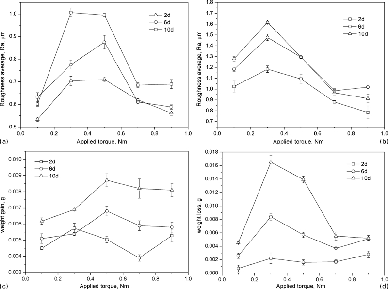
Measured roughness average of a carbon fibre specimen and b aluminium specimen, c increased weight of carbon fibre specimen and d decreased weight of aluminium specimen as function of applied torque and experimental time with abrasive paper of grade 1000 in 3·5% artificial seawater for galvanic couples without CEC
With the increasing applied torque, the surface roughness average and weight change increase. They reach the highest values at the applied torque of 0·3 or 0·5 N m for both of the carbon fibre and aluminium specimens. Then, the roughness average and weight change decrease rapidly with increasing applied torque.
When the applied torque is low, the crevice between carbon fibre and aluminium specimens is large enough that the real contact area at the interface is very small. Therefore, the coupled surfaces are corroded slightly. When the applied torque is higher, galvanic corrosion occurs widely in the surfaces, and the surfaces are corroded seriously. It is similar to the high roughness average; when the applied torque is very high, oxygen cannot enter the contact interface, and the cathode reaction cannot proceed, which weakens the galvanic corrosion.
The experiments were performed for 2, 6 and 10 days. It is found that with increasing experimental time, the surface roughness average and weight change increase. For the same experimental conditions, the aluminium specimen is corroded more seriously due to that the roughness average and weight change are larger than the carbon fibre specimen.
Effects of grinding condition and applied current for galvanic couples with CEC
The measured roughness average and weight change of the carbon fibre and aluminium specimens with the applied torque of 0·3 N m in 3·5% artificial seawater for the galvanic couples with CEC for 12 h are shown in Fig. 5.
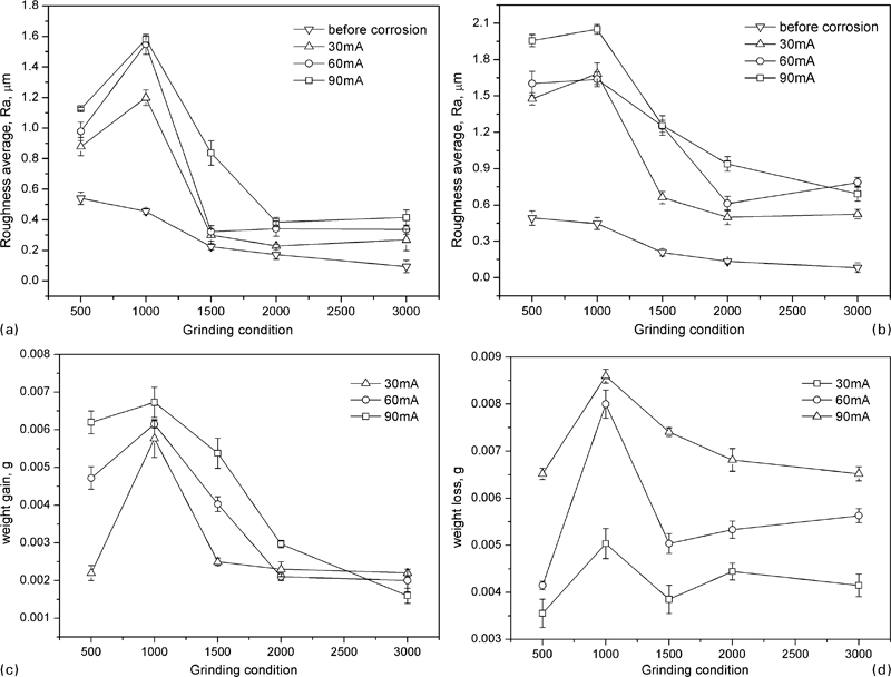
Measured roughness average of a carbon fibre specimen and b aluminium specimen, c increased weight of carbon fibre specimen and d decreased weight of aluminium specimen as function of grinding condition and applied current with applied torque of 0·3 N m in 3·5% artificial seawater for 12 h for galvanic couples with CEC
Comparing with Fig. 3, it can be seen that the grinding condition has similar effects. When the abrasive paper is grade 1000, the surface roughness average and weight change reach the maximum. For galvanic corrosion with abrasive paper of grade 1000 and applied torque of 0·3 N m in 3·5% artificial seawater, it is corroded almost the same for the couple with CEC at 60 mA applied current for 12 h as that for the couple without CEC for 10 days. Therefore, the applied current accelerates the galvanic corrosion obviously.
In addition, with the increasing applied current, the surface roughness average and weight change increase. It is different from previous reports that not any deterioration of steel counter electrode was observed;10 in this study, the aluminium specimen is corroded seriously for the galvanic couple with CEC due to the existence of chlorine.
Effects of applied torque and experimental time for galvanic couples with CEC
The measured roughness average and weight change of the carbon fibre and aluminium specimens with the abrasive paper of grade 1000 and applied current of 60 mA in 3·5% artificial seawater for the galvanic couples with CEC are shown in Fig. 6.
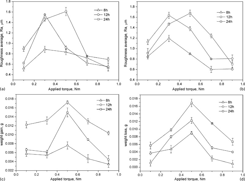
Measured roughness average of a carbon fibre specimen and b aluminium specimen, c increased weight of carbon fibre specimen and d decreased weight of aluminium specimen as function of applied torque and experimental time with abrasive paper of grade 1000 and applied current of 60 mA in 3·5% artificial seawater for galvanic couples with CEC
Comparing with Fig. 4, it can be seen that the applied torque has similar effects. When the applied torque is 0·3 or 0·5 N m, the surface roughness average and weight change reach the maximum. In addition, with the increasing experimental time, the surface roughness average and weight change increase. The corroded surfaces of the carbon fibre and aluminium specimens have similar roughness average and weight change for the galvanic corrosion without CEC for 10 days and the galvanic corrosion with CEC for 12 h. The results verify that the applied current can accelerate galvanic corrosion.
Corrosion morphology
Figure 7a and b shows the control pieces, which show the SEM images of carbon fibre and aluminium before galvanic corrosion. It can be seen that the fibre and epoxy resin are not corroded, and part of the fibre can be observed because of grinding. Similarly, no corrosion was observed in the aluminium specimen, and only some scratch caused by grinding can be seen. Figure 7c–e shows the SEM images of carbon fibre composite and aluminium with the abrasive paper of grade 1000, applied torque of 0·3 N m in 3·5% artificial seawater for 10 days for the galvanic corrosion without CEC. It can be seen from Fig. 7c that the fibre is corroded at the edge, and electrical current is considered as the main reason for fibre corrosion.10 The epoxy resin cracks in the surface, and the debonding event occurs at the interface of the fibre and epoxy resin due to the attack of epoxy resin by hydroxide ions in the high pH environment near the cathode surface. For the carbon fibre plies with 90° winding angle, it can be seen from Fig. 7d that the epoxy resin is peeled off and fibres appear. The epoxy resin is attacked more seriously than carbon fibre. The aluminium is attacked because of the anode reaction, and the corrosion product tends to be unstable in moisture and causes pitting, which aggravates corrosion. The pitting with the diameter of ∼3 μm can be seen in the surface of the aluminium specimen, as shown in Fig. 7e.
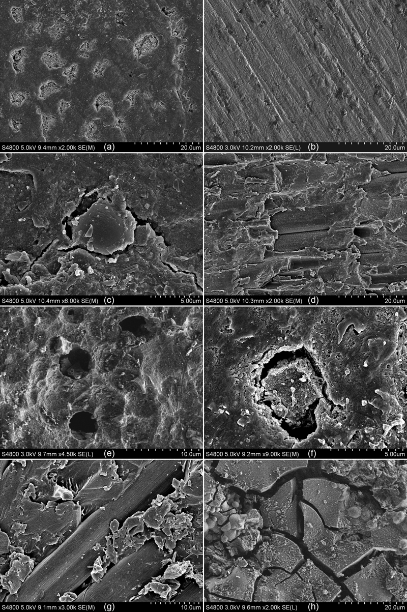
Images (SEM) of a carbon fibres and b aluminium before galvanic corrosion; c, d carbon fibres and e aluminium for galvanic corrosion without CEC with abrasive paper of grade 1000, applied torque of 0·3 N m in 3·5% artificial seawater for 10 days; and f, g carbon fibres and h aluminium for galvanic corrosion with CEC with abrasive paper of grade 1000, applied torque of 0·3 N m and applied current of 60 mA in 3·5% artificial seawater for 12 h
Similar micrographs can be seen for the carbon fibre composite and aluminium with the abrasive paper of grade 1000, applied torque of 0·3 N m and applied current of 60 mA in 3·5% artificial seawater for 12 h for the galvanic corrosion with CEC, as shown in Fig. 7f–h. The carbon fibre is corroded more seriously because of the action of the applied current. The debonding and delamination of epoxy resin is more obvious, as shown in Fig. 7f and g. For the aluminium, no pitting is found in the surface. However, serious crack occurs, as shown in Fig. 7h, which is also considered as the results of applied current.
Conclusions
This paper studies the effects of grinding condition, concentration of artificial seawater, applied torque, applied current and experimental time on the galvanic corrosion behaviour of carbon fibre composite coupled to aluminium.
With the improving grinding condition and increasing applied torque, the roughness average, weight gain of carbon fibre specimen and weight loss of aluminium specimen increase, reach maximum and then decrease for the galvanic corrosion with and without CEC.
With the increasing concentration of artificial seawater, applied current and experimental time, the roughness average, weight gain of carbon fibre specimen and weight loss of aluminium specimen also increase for the galvanic corrosion with and without CEC.
Galvanic corrosion can be accelerated by applied current, which is considered as the main reason for carbon fibre attack.
According to the SEM, carbon fibre is corroded at the edge, epoxy resin cracks in the surface, debonding event occurs at the interface of fibre and epoxy resin and pitting or crack occurs in the surface of aluminium.
Footnotes
Acknowledgements
The authors wish to acknowledge the financial support of the National High-Technology Research and Development Program of China (grant no. 2007AA09A101), the National Natural Science Foundation of China (grant no. 50874115), the Taishan Scholar project of Shandong Province (grant no. TS20110823), the Science and Technology Development Project of Shandong Province (grant no. 2011GHY11520) and the Incubation Programme of Excellent Doctoral Dissertation of the China University of Petroleum (grant no. 2010-02).