
Abstract
This paper reports on the corrosion of Mg alloy AZ31 in simulated body fluid (SBF) using static immersion tests and electrochemical impedance spectroscopy. A preliminary study on the effect of flowing SBF on the corrosion behaviour of AZ31 has also been carried out. Low toxicity ionic liquids (ILs) trimethyl(butyl)phosphonium diphenyl phosphate P1444DPP and trihexyl(tetradecyl)phosphonium bis-2,4,4trimethylpentyl-phosphinate [P66614][i(C8)2PO2] have been used to provide corrosion protection for AZ31 in SBF. Time dependent immersion tests indicate that under static conditions, AZ31 suffers severe localised corrosion in SBF, with pits developing predominantly beside the Al–Mn intermetallic phase in the α matrix. At longer immersion times, the corrosion product eventually precipitates and covers the entire specimen surface. When exposed to SBF under flowing conditions with a shear stress of 0·88 Pa, more uniform corrosion was observed. The optical profilometry results and electrochemical impedance spectroscopy analysis suggest that both P1444DPP and [P66614][i(C8)2PO2] pretreatments can increase the corrosion resistance of AZ31 in SBF, in particular by decreasing the number of deeper pits found on the alloy surface. Cytotoxic test shows that the presence of the ILs P1444DPP and [P66614][i(C8)2PO2] in cell culture media slightly inhibits the growth of human coronary artery endothelial cells in comparison with the good cell viability around the treated specimen. A pretreatment with IL is used in order to improve the corrosion resistance of this alloy in SBF.
Keywords
Introduction
Implanting artery stents into diseased arteries is considered an effective treatment for coronary artery diseases.1 For some time, permanent metallic stents have been widely used, but it is often claimed that the continued presence of the stent after vessel remodelling is unnecessary.1 The stent acts as a foreign body engendering long term risks and that the stent inside the coronary artery as a foreign object presents long term risks of chronic inflammation2 in stent restenosis2 and late thrombosis.3 Thus, the development of biodegradable coronary artery stents is very important. A biodegradable stent can be gradually dissolved and adsorbed after an artery is remodelled, avoiding medical complication.4
The use of magnesium alloys to construct biodegradable coronary artery stents has attracted attention recently.1 Mg alloys are the fourth most abundant cation naturally present in the human body, they are involved in many metabolic reactions and physiological mechanisms, excess Mg2+ can be excreted in urine,1,5 and so the major degradation product is readily dealt with. The excellent mechanical properties of Mg alloys mean that they are strong enough to maintain the opening required in a coronary artery. Most alloying additives reduce the rate of corrosion of magnesium alloys; however, for biomedical applications, the amount of these alloying additives is strictly limited, and some elements (e.g. Zr, Cd, rare earths and heavy metals) are restricted.6 In this study, Mg alloy AZ31 with ∼3%Al content was chosen as a candidate material. The presence of Al not only improves the mechanical properties but also enhances the corrosion resistance.7 Previous research has shown that this alloy is non-allergenic in an epicutaneous patch test.8 Unfortunately, because the oxide–hydroxide films that form on the surface of magnesium alloys (including AZ31) on exposure to air provided poor protection to the underlying metal,9 these alloys corroded very rapidly in the body, resulting in subcutaneous hydrogen gas bubbles,10 an increase in local pH10 and potential loss of the structural integrity of the stent before the arteries can be fully remoulded. Consequently, while the potential of using a magnesium alloy (e.g. AZ31) as the primary material for biodegradable coronary artery stents is obvious, their use has thus far been limited.1 Further work is required to understand the corrosion behaviour of these alloys and the relationship between the information obtained from in vivo corrosion tests and that from more laboratory testing through the use of dynamic corrosion test protocols.
Controlling the corrosion rate of magnesium alloys in the body is critical in the development of biodegradable magnesium alloys stents. Much research has been carried out to improve the corrosion resistance of magnesium alloys, mainly through the use surface coatings.10 Typical conversion coatings (such as chromate conversion coating and phosphate permanganate conversion coating) and anodising are two of the effective processes employed.11 However, these surfaces are unlikely to be biocompatible. Thus, the development of an improved method to control the degradation rate of Mg alloys in the body without any adverse effects is desirable. One approach recently found to be promising for controlling Mg corrosion in chloride contaminated aqueous media is the use of pretreatment of the alloy surface with ionic liquids (ILs). An IL is a low temperature molten organic salt (melting point below 100°C).12 The ILs have many unique properties, such as a high concentration of species reactive with a metal surface, high stability and low volatility.13 In recent years, the corrosion protection properties of ILs have generated great interest through their potential to form protective surface films on reactive metals. Passivation of a reactive metal by an IL was identified by Howlett et al.14 in studies of lithium batteries using bis(trifluoromethylsulfonyl) (Tf2N) based IL as the electrolyte. It was also noted by Uerdingen et al.15 that many alloys showed very good corrosion resistance after contact with ILs. Thus, if an IL is chosen that can react with an Mg alloy surface to provide some corrosion protection and also produce a surface, which is non-toxic to human cells, then IL pretreatment could also be used to control the biodegradation rate of Mg alloys in the human body.
To explore the possibility of employing a particular magnesium alloy for stents, an understanding of the biocorrosion behaviour of the alloy in the human body is essential through in vivo testing.16 However, in vivo testing has many drawbacks, such as time, cost and the potential discomfort and harm to the experimental subjects,16 all of which limit its efficiency. Therefore, recent research with AZ316,17,18 has been undertaken using simulated body fluid (SBF), which contains a similar inorganic composition to human blood plasma. Despite this prior work, the surface corrosion processes (in particular the early stages) and the corrosion mechanism for AZ31 in SBF are still not well understood. In contrast to previous published work, here, we focus predominantly on the early stages of corrosion during immersion tests and a more in depth and targeted analysis of electrochemical impedance spectroscopy (EIS) data. The latter assists in understanding the changes in the corrosion processes with this alloy in SBF as a function of time. Considering that the stents placed into the blood vessels are in a dynamic environment, and that flow rate may significantly affect the corrosion of an alloy, we also report on the influence of a flowing environment on the corrosion behaviour of AZ31. A flowing environment test cell was designed to mimic, as near as possible, the physiological conditions to which a stent is subjected in the coronary artery.
This paper thus discusses the corrosion processes, in particular the initiation of corrosion on AZ31 in SBF. The effect of flow on corrosion behaviour and the ability of IL pretreatment to modify degradation have been investigated.
Experimental
Alloy and specimens
The magnesium alloy used in this investigation was a direct strip cast cylinder of AZ31 magnesium alloy, with a nominal composition of 3%Al, 1%Zn, etc. In order for all specimens to have similar microstructure, they were taken around the circumferential edge of the cylindrical casting.
For the constant immersion corrosion (static) tests and the EIS tests, specimens were mounted in epoxy resin to expose a test area of 10×6 mm. For the flow cell corrosion (dynamic) tests, cylindrical specimens with a diameter of 10 mm and a length of 25 mm were used. The circular section of the specimens was exposed to the environment with the flow test.
All the specimens were ground with SiC paper to a 4000 mesh surface finish under running tap water. They were rinsed with distilled water and acetone and then dried under a nitrogen stream. The specimens were stored in a vacuum desiccator for 24 h to stabilise the oxide film that forms immediately after abrasion upon exposure to the air environment. The interface between the specimens and the epoxy resin was sealed using nail polish lacquer to avoid potential crevice corrosion.
Simulated body fluid
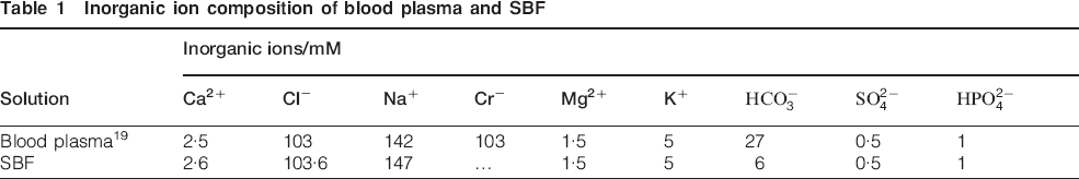
A commercially available SBF was chosen as the test solution due to its similar ionic composition to that of human blood plasma. Table 1 shows the composition of the SBF used in this work and a typical blood plasma. The pH of the SBF solution was 7·4±0·5.
Inorganic ion composition of blood plasma and SBF


Ionic liquids
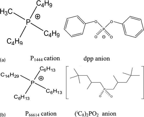
Trimethyl(butyl)phosphonium diphenyl phosphate (P1444DPP) was prepared in the laboratory. Trihexyl(tetradecyl)phosphonium bis-2,4,4trimethylpentyl-phosphinate {[P66614][(iC8)2PO2]} was obtained from Cytec Industries. The ILs were purified by passing through a column containing a filter agent, alumina and sand to remove any impurities. The schematic structures of the anion and cation that make up the molecule P1444DPP and [P66614][(iC8)2PO2] are shown in Fig. 1.
Ionic liquid pretreatment
Previous research21 has found that a specimen heated to 50°C in room temperature IL for a period of time was an advanced IL treatment method. With this treatment, the AZ31 was heated to 50°C using an oven. A thin layer of room temperature IL was placed over the whole surface of the specimen using a syringe. The approximate volume of IL was 1·5 mL, and the approximate thickness of the IL film was 2 mm.
Constant immersion corrosion tests
Plastic beakers containing 100 mL of the SBF were used for these tests. The SBF was maintained at 37°C in a constant temperature water bath. Specimens with no IL pretreatment were immersed in beakers for 1 min, 10 min, 2 h, 24 h and 168 h. The IL pretreated specimens were immersed for 2 h.
Flow cell corrosion tests
A flow cell was designed to simulate the blood flowing in the coronary artery vessels. The schematic of the flow cell is shown in Fig. 2. The test channel was made of transparent polymethylmethacrylate to allow the specimen to be observed. The flow rate in the constricted section of the test channel was designed to produce a shear stress in the flowing stream of SBF of 0·88 Pa for this preliminary work. The specimens were inserted into the test channel such that the diametric plane was exposed to the flowing SBF. Exposure times of 10 min and 2 h were used.
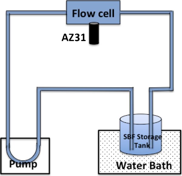
Schematic diagram of flow cell
Scanning electron microscopy and optical profilometry
After immersion, the corroded specimens were examined in an SEM. Energy dispersive X-ray spectroscopy (EDX) was used to identify the composition of the corrosion product. After immersion, the specimens were immersed for 60 s in a solution of 200 g chromium trioxide, 10 g silver nitrate and 20 g barium nitrate in 1000 mL of distilled water to remove the corrosion products. The depth and number of pits were determined using a Veeco Contour GT-K1 optical profilometer.
Electrochemical impedance spectroscopy
Electrochemical impedance spectroscopy tests were carried out using a three-electrode cell. The volume of the SBF was 250 mL open to the air. An Ag/AgCl electrode was used as a reference electrode and a titanium mesh as the auxiliary electrode. An EG&G PAR VMP2/Z multichannel potentiostat was used to process the current–time and voltage–time data to provide the impedance at different frequencies.22 The measurements were taken over a frequency range of 200 kHz to 50 mHz with eight points per decade using a 10 mV amplitude perturbation. Electrochemical impedance spectroscopy spectra were acquired at 1 h intervals. The Zfit program in the EC-Lab software was used to fit the equivalent circuits to the EIS experimental data.
Cytotoxic test of ILs
The cytotoxicity of the ILs was determined using primary human coronary artery endothelial cell (HCAEC) line. Cells were obtained from Lonza (Australia) and maintained in growth medium containing SingleQuot supplements (Lonza, Australia). Three ILs, previously investigated12,13 for corrosion protection of magnesium alloys, were chosen: P1444DPP, [P66614][i(C8)2PO2] and P66614DPP.
Stainless steel (SS) sheets were used for the tests. They were treated with IL and exposed to ultraviolet light for 20 min each side in a 24 well plate. The HCAECs were added onto the plate at a density of 1·5×104 cells/cm2. The numbers of adherent cells on the IL treated specimens were quantified using a Quant-iTTM PicoGreen dsDNA Assay Kit after 96 h of culture. An untreated specimen was used as control.
Results and discussion
Behaviour of Mg alloy AZ31 in static SBF
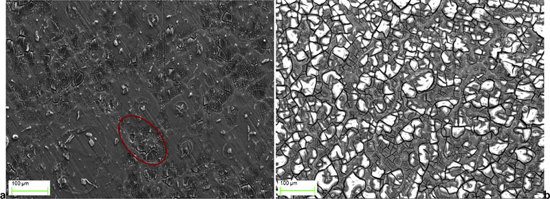
In this initial investigation, the corrosion behaviour of AZ31 was examined with immersion of specimens in SBF under static condition in different times. Figures 3 and 4 present the SEM images of corroded surfaces, which had been immersed for 1 min, 10 min, 2 h, 24 h and 168 h. Initially, the corrosion product accumulated around the intermetallic particles (Fig. 3). After 10 min, the corrosion product generally covered these intermetallic particles. Energy dispersive X-ray spectroscopy analysis of the intermetallic particles (e.g. A in Fig. 3a) revealed that they contained mostly Al, Mn and Mg. The Al–Mn particles are shown to be present in the magnesium α matrix of AZ31.23 These particles are more cathodic than both the β phase and the Mg matrix.23 Therefore, the corrosion of AZ31 in SBF initiated from these Al–Mn particles as a result of the galvanic difference between them and the surrounding matrix. With increased immersion time, general corrosion of the Mg matrix occurred as a result of breakdown of the passive film [mainly a mixture of MgO and Mg(OH)2], with the corrosion product eventually covering the whole surface. In Fig. 3b, ‘mud cracking’ is evident on many of the surfaces. These ‘mud cracks’ developed during drying of corrosion product in the SEM.
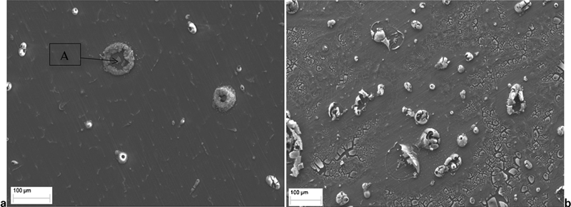
Corrosion product morphology of AZ31 after immersion in SBF for a 1 min and b 10 min
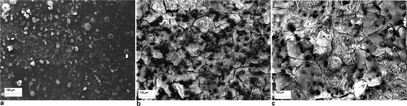
Images (SEM) of AZ31 specimens after immersion in SBF for a 2 h, b 24 h and c 168 h
With future immersion times of up to 2, 24 and 168 h, non-uniform and highly cracked corrosion product layers were clearly visible over the entire surface of AZ31. Mud cracking was particularly evident on the specimens exposed for 24 and 168 h. The greater extent of mud cracking indicates a thicker layer of corrosion products. The EDX data obtained after 24 h immersion in SBF (Fig. 5b) show the presence of O, Mg, Ca and P on the surface of the corroded AZ31. This is consistent with the observation reported previously.6 The presence of O and Mg indicates a corrosion product of MgO and Mg(OH)2, while Ca and P arise from components of the SBF solution. The relation between Mg corrosion and the deposition of calcium phosphate has previously been discussed, which suggested that Mg corrosion had an influence on the precipitation process of Ca and P from the SBF.24 The accumulation of calcium phosphate has also been found during in vivo tests.25 For an Mg based stent, calcium phosphate deposits would be undesirable and could under some circumstances threaten the life of a patient with an implant. Large precipitates of calcium phosphate deposits could block an artery near the stent or travel to the other parts of the body. The precipitation of the corrosion product is associated with the local increase in pH due to cathodic reaction accompanied by the dissolution of the Mg alloy matrix. A reduction in corrosion rate would mean a smaller increase in local pH, which in turn would influence this precipitated process.
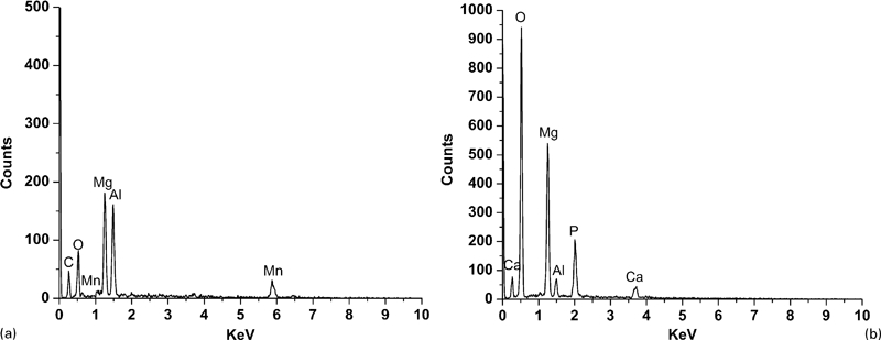
Energy dispersive X-ray spectroscopy data obtained from a particle A in Fig. 3a and b corrosion products on surface of specimen in Fig. 4b after immersion in SBF for 24 h
Electrochemical impedance spectroscopy
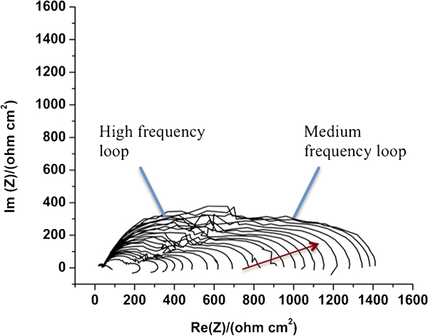
To investigate in more detail the electrochemical corrosion mechanism, EIS was conducted with an AZ31 electrode surface in SBF, and the responses over a wide frequency range were recorded. Analysing these responses and using an appropriate equivalent circuit to fit the EIS data provided information on the corrosion process. Figure 6 shows successive Nyquist impedance plots obtained at 1 h intervals during immersion of AZ31 in SBF under static conditions. The shape of these data is characterised by two ‘depressed’ capacitive loops at high and medium frequencies. With increased immersion time, the general shape of these plots did not significantly change, indicating that the corrosion process did not significantly change with immersion. Both real and imagery impedances for high and medium frequency loops were observed to increase with immersion time. It is thought that26 the high frequency loop is associated with the film of the corrosion product, and the medium frequency loop could be due to charge transfer resistance and double layer capacitance, which form between the corroded layer and the metal substrate. At the metal interface, when the solution reaches the metal surface, a charged double layer is established. The fact that there was an increase in high frequency loops indicates that the corrosion product was kept on accumulation on the surface during the 24 h immersion. The accumulation of corrosion product would increase the charge transfer resistance (R t). Hence, the medium frequency loop increased with immersion time. Figure 7 shows the corrosion product layer with a certain thickness formed on the surface of AZ31 after immersion in SBF solution for 24 h. We should note that there were cracks existing in the corrosion product layer, so the SBF could still diffuse through these cracks to the metal surface and enable corrosion.
Typical Nyquist impedance spectra obtained at 1 h interval during immersion of AZ31 in SBF
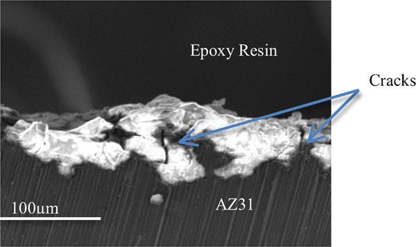
Scanning electron microscopy observation of cross-section of layer formed on surface of AZ31 in SBF for 24 h
An equivalent circuit was fitted to the Nyquist data. A schematic of this circuit is presented in Fig. 8. This circuit consists of a resistor representing the electrolyte resistance R e, and two RC units in series that describe the interfacial properties of working electrode: a charge transfer resistance R t in parallel with the double layer capacity, C d, and a capacity associated with the surface film of corrosion product Q f, in parallel with a surface resistance of corrosion product R f. Here, the constant phase element was used to represent a ‘non-ideal’ capacitance. The circuit provided a good fit, with χ 2 being ∼0·004. One fitting example is shown in Fig. 9. This circuit is consistent with the physical observation as observed in the SEM, that is, corrosion occurring beneath surface.
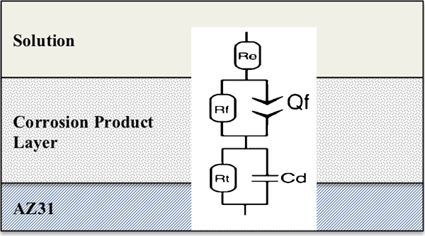
Equivalent circuit for AZ31 immersion in SBF (note: R t, charge transfer resistance; C d, double layer capacity; Q f, capacity associated with surface film; R f, surface resistance; R e, electrolyte resistance; average value of constant phase element a parameter = 0·830)
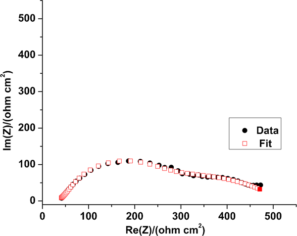
Example of fit to data (χ 2 = 6·922e −3)
Table 2 presents the parameters obtained from fitting the equivalent circuit to the data. It can be observed that C d decreased with the increased immersion time. Meanwhile, R t increased. The changes of C d and R t with immersion could be explained by the high corrosion reactivity of the AZ31 in SBF. As observed from Figs. 3 and 4, the corrosion product progressively covered the whole surface with increasing immersion time, and the accumulation of corrosion product would increase the charge transfer resistance (R t). The increase in R t diminished the charge accumulation on the electrical conductors of double layer capacitor, leading to a reduction in double layer capacitance C d. The increase in R t indicates a decrease in the corrosion rate resulting from the corrosion product accumulation on the surface, so a thick corrosion product layer provides some protection for AZ31 in SBF. Both C f and R f increased with immersion time, which is also due to the progressive accumulation of corrosion products. The accumulation of corrosion product increases not only the thickness of the corrosion product layer (d) but also the coverage area (A). It is clear that with time, A increased at a faster rate than d; hence, C f, which is proportional to the A/d, increased.
Parameter determined from Randles circuit fit to data
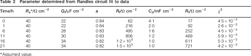
*Assumed value.
It is interesting to compare the EIS data with the pure Mg in aerated Na2SO4 by other works.27 AZ31 in SBF had a similar evolution of impedance behaviour with pure Mg in aerated Na2SO4; this suggests that the corrosion process of AZ31 in SBF was dominated by the dissolution of the Mg matrix. However, the change in medium frequency loops was significantly different. With AZ31 in aerated Na2SO4, the medium frequency loops slightly changed with immersion time. One possible explanation is that the corrosion product layer of AZ31 in Na2SO4 mainly consisted of Mg(OH)2, which had a porous structure, leading to a large exposed metal area in the aggressive solution. With SBF, the existence of Ca and P in the corrosion layer could increase the density of the corrosion product layer, and thus, the exposed area in the solution was decreased with time. Therefore, the charge transfer resistance R t in the SBF would have been larger than that in Na2SO4.
Effect of flowing SBF
The appearance of the corroded surface after immersion in flowing SBF for 10 min and 2 h is shown in Fig. 10. In comparison with specimens exposed to static SBF, a significant difference in corrosion morphology was evident. In flowing SBF (Fig. 10a), little corrosion product was observed around the intermetallic particles, while in the static environment, well defined precipitates of corrosion product around intermetallic particles were evident (Fig. 3b). The reason for this difference lies in the fact that under flowing SBF, the specimen was constantly flushed by the circulation of the test solution over the specimen surface; this would have prevented a rise in local pH, thus reducing localised precipitation of corrosion product around the intermetallic particles, promoting a more uniform corrosion product layer. However, in the static environment, the corrosion product precipitated around the intermetallic particles and led to localised corrosion.
Corrosion product morphology of AZ31 after immersion in flowing SBF for a 10 min and b 2 h
The circled area in Fig. 10a shows an area on the corroded surface, which may have been removed by the flow of liquid. After 2 h immersion in the flow cell, a more uniform corrosion product film was visible on the surface of AZ31, in comparison with the film formed on the specimen exposed to static SBF environment.
These SEM observations suggest that with a flowing SBF (shear stress = 0·88 Pa), a more uniform corrosion product morphology developed. At this stage, no data are available to allow a comparison of corrosion rate between the static and the flowing SBF condition. Also, the effect of flow rate (shear stress) is yet to be determined. This effect will be reported in the future publication.
Effect of IL pretreatment on corrosion
Cytotoxicity of ILs
To test the cytotoxicity of ILs, SS specimens treated with ILs were immersed in the cell culture for 72 h. Figure 11 shows the HCAEC morphology after 72 h culture. Live cells were observed around the surface of specimens pretreated by P1444DPP and [P66614][i(C8)2PO2]. However, compared with the control specimen (no IL pretreatment), there was a significant reduction in cell density. Less live cells were observed around the surface of the P66614DPP pretreated specimen. The statistics of live cells in Fig. 12 confirmed the observation. Therefore, specimens pretreated by P1444DPP and [P66614][i(C8)2PO2] are relatively low toxic to HCAEC.
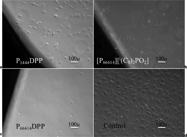
Human coronary artery endothelial cell morphology after 72 h culture with a P1444DPP pretreated SS, b [P66614][i(C8)2PO2] pretreated SS, c P66614DPP pretreated SS and d control SS
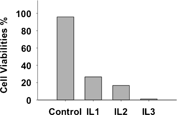
Human coronary artery endothelial cell viabilities after 96 h culture with IL treated SS {IL1: P1444DPP, IL2: [P66614][(iC8)2PO2], IL3: P66614DPP}
Difference of corrosion behaviour
In order to qualify the protection performance of the IL treatment, the corrosion product was removed after immersion, and the depth of corrosion was measured using optical profilometry. The three-dimensional optical profiles of the corroded surfaces are shown in Fig. 13, which reveal the variation in the corroded area on the differently surface treated specimens. For the P1444DPP pretreated AZ31, this figure clearly shows that the corroded area was reduced. For the [P66614][i(C8)2PO2] pretreated AZ31, the corroded area was relatively larger than the P1444DPP pretreated AZ31, but it was still smaller than the control sample. Hence, qualitatively, pretreatment of these two ILs can offer some protection for the AZ31 from corrosion in SBF.
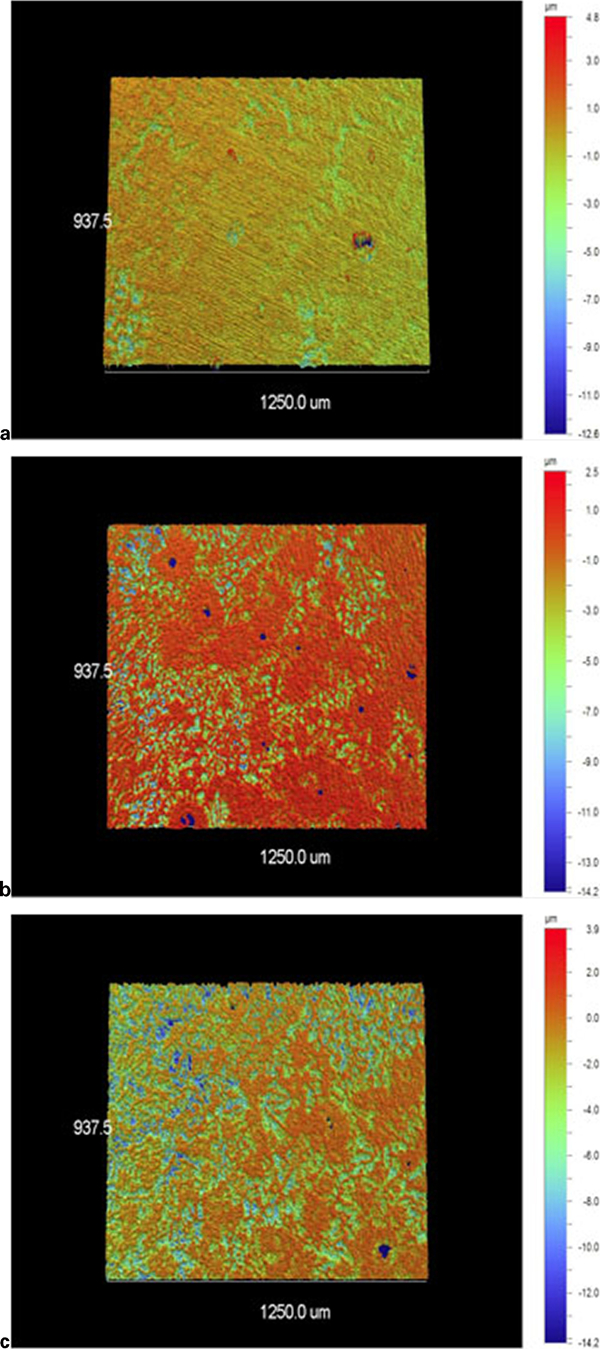
Corroded surface of a P1444DPP pretreated AZ31, b [P66614][i(C8)2PO2] pretreated AZ31 and c control observed by optical profilometry (coloured version available online)
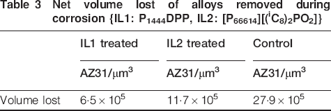
To better compare the protective properties of the IL, pit number, pit depth and volume lost were recorded from an area of 937·5×1250·0 μm on each of the specimens shown in Fig. 13. The histogram in Fig. 14 shows the distribution of pit depths with corresponding pit numbers. Zero pit depth corresponds to areas of no corrosion, and values on the x axis a little greater than zero correspond to peaks associated with the grinding damage from specimen preparation. It is immediately apparent that the distribution of pit depths on the IL treated specimens differed significantly from the untreated surface. In particular, larger pits were absent on the surface treated with P1444DPP (<3 μm deep and a fairly sharp distribution), while some pit depths on the [P66614][i(C8)2PO2] pretreated specimen approached 9 μm deep. In contrast, the untreated sample appeared to have a broader distribution of pits, and these were skewed to larger pit depths. There were a greater number of pits on the control specimen compared with the IL treated specimens. The volume of alloy removed from the surface due to pitting was also calculated and presented in Table 3. These data also clearly demonstrate that, with these two IL pretreatments, a smaller volume of alloy was removed by corrosion during the immersion for 24 h in SBF, suggesting that such pretreatments can increase the corrosion resistance of AZ31 in SBF. Furthermore, the IL treatment appeared to decrease the depth of pitting and led to a greater number of shallow pits, which could ultimately appear as ‘uniform’ corrosion. For the corrosion of coronary artery stents in the body, uniform corrosion is optimal. The IL pretreatment can increase the possibility of uniform corrosion.

Histogram results from optical profilometry analysis of control AZ31 and IL pretreated AZ31 after immersion in SBF for 24 h {IL1: P1444DPP, IL2: [P66614][(iC8)2PO2]}
Net volume lost of alloys removed during corrosion {IL1: P1444DPP, IL2: [P66614][(iC8)2PO2]}
The protective effect of the IL was also accessed using data from the EIS test. Figure 15 shows the variation in film resistance with immersion time, which is extracted from the EIS spectra. These data clearly indicate that the film resistance of both IL pretreated specimen and control specimen increased rapidly after immersion in SBF. The significant modification of surface film resistance during immersion can be attributed to high reactivity of the AZ31 in SBF. The existence of a protective IL passive film on AZ31 is confirmed by a higher film resistance at the beginning of immersion (0 h). The film resistance on the IL treated specimen did not increase with time as much as the untreated specimen. This indicates that the presence of IL reduced the amount of corrosion product, which developed on the surface, and that is reducing corrosion rate. However, corrosion still occurred in the presence of IL, and this could be due to a heterogeneous and/or defective film of IL. For a film to provide protection on an Mg alloy for coronary artery stent, a homogeneous film with uniform coverage across the entire surface will be required. Such a film may have an ‘ideal’ rate of change of film resistance in SBF, as shown by the dashed line in Fig. 15. This slower rate of increase would represent a slow rate of corrosion that the body can tolerate, making sure that the coronary artery stent can keep its mechanical integrity before the diseased vessel returns to its original shape, and be gradually degraded and absorbed in the body.
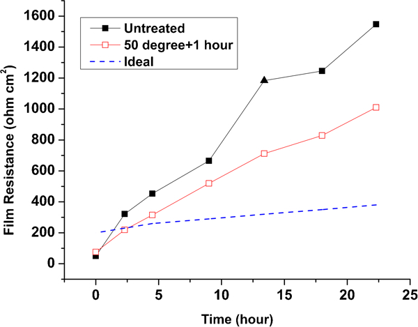
Film resistance of AZ31 versus exposure time
Conclusions
Corrosion of Mg alloy AZ31 in static SBF initiates beside Al–Mn intermetallic particles in the Mg matrix. With increased immersion time, a thick and non-homogeneous corrosion product layer eventually covers the whole surface. The EDX analysis indicates the presence of Mg, O, Ca and P in the corrosion product layer. Mg and O are most likely Mg(OH)2, and Ca and P rise from the components in SBF. Electrochemical impedance spectroscopy analysis confirms the growth process of the corrosion product layer on the surface of AZ31 in SBF. The corrosion product layer can provide corrosion protection for AZ31 in SBF, but as there are cracks in the corrosion product layer, corrosion of AZ31 still continues. In the flowing condition, the circulation of the SBF over the surface of the specimen inhibits the local pH increase, thus avoiding localised corrosion and promoting more uniform corrosion product morphology.
The cytotoxic test shows that SS pretreated by P1444DPP and [P66614][i(C8)2PO2] is relatively low toxic to HCAEC. Using these two ILs that pretreat the AZ31, the IL pretreatment can increase the corrosion resistance of AZ31 in SBF and the possibility of uniform corrosion. However, IL pretreatment cannot provide good corrosion protection for AZ31 in SBF. One possible reason is that the IL film formed by this treatment method is defective and/or heterogeneous.
Footnotes
Acknowledgements
The authors would like to acknowledge Boston Scientific and ACEs for funding the linkage project no. LP0990621. Special thanks to S. Moulton (University of Wollongong) and J. Weber and T. Schenermann (Boston Scientific) for advice and organisation and J. Sun (Monash University and Cytes Industrials) for providing the IL used.