
Abstract
A cathodically protected buried pipeline is usually connected to earthing electrodes via several capacitive AC mitigation devices placed at various locations along the pipeline in order to decrease the AC voltage interference. During periodic switching of the cathodic protection circuit for the instant Eoff measurements, the capacitive AC mitigation devices tend to be discharged through the soil provoking an error in the instant Eoff readings, thus resulting to a possible false evaluation of the cathodic protection effectiveness. The aim of the present work is to investigate the role of the main factors, which influence this error. An electric circuit simulation of the pipeline with connected earthed capacitors is proposed. The circuit analysis has shown that the key determining factors of the aforementioned capacitive discharge time constant comprise the capacitance value of the capacitive AC mitigation device at every earthing site, the number of earthing sites where the capacitive AC mitigation devices are installed, the earthing electrodes resistance and the pipeline (or coating) resistance to remote earth. Measures to minimise this misleading error of Eoff readings through the control of the abovementioned factors and the modification of the time of the Eoff measurement are suggested. In this context, the Eoff should be measured at prolonged time after every switching, contrary to the usual practice. Furthermore, the capacitive AC mitigation devices should not be disconnected from the pipeline in order to prevent the adverse effects of AC interference on cathodic protection monitoring. The present work contributes to the understanding of the capacitive AC mitigation devices effect on pipeline cathodic protection monitoring, which has been rarely analysed in the past. Moreover, by recommending novel approaches, the paper can stand as a reference to the cathodic protection operators for a simple, reliable and economic monitoring of the cathodic protection effectiveness in presence of earthed capacitive AC mitigation devices.
List of symbols
double layer capacitance
capacitance of i-capacitive AC mitigation device
pipeline capacitance
capacitance of the pipeline with intact coating
groundbed resistance
resistance of coating defect to remote earth
pore resistance
longitudinal pipeline resistance
polarisation resistance
pipeline resistance to remote earth
resistance of the pipeline with intact coating
ground resistance at i-capacitive AC mitigation device site
C.P. transformer/rectifier
polarisation voltage
Introduction
The reliability of cathodic protection (CP) depends on whether the potential measurement is free of errors or not. The main source of errors results from voltage drops in the soil.1 The instant Eoff readings acquired by means of the on/off technique through periodic on/off switching of the CP circuit of a pipeline do not always represent the true, i.e. IR free, cathodic protection potential due to the voltage drop in the soil originating from DC stray currents of various external sources,2 telluric,3 equalising,4 – 6 long line7 or galvanic currents.8
The AC voltage induced on the pipeline by high voltage power lines is another source of error for the CP potential.4,8 As the AC voltage on the pipeline may create safety risks (e.g. electric shock to humans or livestock) and may be detrimental to pipeline integrity in terms of corrosion (AC corrosion), the pipelines are commonly connected to earth via AC coupling DC decoupling devices. These devices drain AC from the pipeline while simultaneously block DC without interfering with CP effectiveness. Nevertheless, the CP potentials can be falsified either by the ineffective DC blocking or by the ineffective AC mitigation of some of these devices (e.g. thyristor type overvoltage arresters).8
Corrosion coupons and polarisation probes have been adapted in order to overcome the previous problems and to acquire reliable values of IR free potential without the aforementioned errors of the conventional instant Eoff measurements.9,10
However, for the determination of instant Eoff of a cathodically protected pipeline, the on/off technique is widely used as it is a simple and economic method. Performing the measurements by this technique even in the case of no interference from any of the aforementioned sources, there is an IR drop due to CP current. Therefore, when the protection current is interrupted, the IR drop in the soil between the pipeline and the reference electrode disappears in a very short time (μs). Therefore, by taking the potential reading shortly after current interruption, the IR drop is no longer included. In this case, the overpotential is also eliminated but over a much longer period than IR drop, ranging from milliseconds for activation overpotential to seconds or even days for concentration overpotential, which is the prevailing one in CP.4
In this work, a novel approach is presented which shows the advantage of CP monitoring without having to disconnect the capacitive AC mitigation devices from the pipeline. Until now the technique to obtain supposedly reliable Eoff measurements used to be the disconnection of capacitive AC mitigation devices from the pipeline.11,12 Although the disadvantage of the time wasted to disconnect and reconnect all AC mitigation devices is avoided by an automatic disconnection system (intelligent switching), the complicated sensitive electronics used to achieve this makes the AC mitigation devices more vulnerable to malfunctions and breakdowns. Moreover, after such a disconnection, the AC voltage is increased again, provoking both safety risks and unacceptable perturbation of the CP parameters.8,13,14
Additionally, the capacitive AC mitigation devices discharging currents falsification effect on the instant Eoff readings is investigated. This phenomenon was observed during CP maintenance measurements on a pipeline (45 km length, ND 30″, 3-layer PE coated and cathodically protected from one rectifier in potentiostatic mode) of the Greek Natural Gas Transmission System of DESFA, following the installation of the so called alternating voltage arresters of continuous function (AVACF), namely a capacitor-like AC coupling DC decoupling device used for AC mitigation. These devices were designed, manufactured and installed at eighteen different positions along the pipeline, with aim to overcome the adverse effects of AC voltage induced on the gas pipeline from nearby overhead high voltage power lines.15
Experimental approach of investigated falsification of Eoff readings
The description of the pipeline on which the experimental measurements were performed, its CP system, the experimental conditions as well as the technical characteristics of the designed and manufactured DC decoupling AC coupling devices (AVACF) have been already presented elsewhere.8,15
A representative Eon/Eoff waveform, before installation of the capacitive AC mitigation devices, is depicted in Fig. 1. This recording is performed using an oscilloscope, namely a Scopemeter, combined with an active AC filter so as to record the DC potential unaffected by AC interference. The measurement sampling rate is 200 ms. In this case the instant Eoff is more accurately obtained at 200-400 ms time lapse after CP-off switching (point A in Fig. 1), i.e. at the break point of the Eon/Eoff waveform. This measurement cannot be accurately performed by a hand held digital multimeter. Therefore, sophisticated instruments are required (e.g. digital oscilloscope with active AC filter or special pen recorder, high acquisition sampling rate data logger). During the CP-off time period between 400 ms and 1 s (period A–D), a depolarisation is observed which causes an error presented as an anodic shift of potential values of ̃50 mV. This depolarisation, which appears in the first milliseconds of A–B period and usually terminates within the first second of CP-off period, may be attributed to activation control. During the rest CP-off time (period D–B) the depolarisation is attributed to diffusion control and is so slow that the potential remains stable (very low depolarisation rate) that is normal in long term polarised well insulated pipelines. Therefore, normally, the error of potential measured at point D or B is not generally high. When measurement is taken on coated structures in overprotection conditions, which is with hydrogen evolution, it is difficult to check Eoff because the activation overpotential of hydrogen evolution may disappear very rapidly, in <100 ms.4 However, in normal CP conditions the prevailing overpotential associated with corrosion protection is the concentration polarisation overpotential that is measured at point D or B in Fig. 1.4,16 This is the main argument in favour of taking the Eoff at longer than 1 s, while, on the contrary, the instant Eoff is suggested by standards17 to be acquired within 1 s after CP-off switching. However, taking into consideration that the potential remains almost stable during the D–B period, the Eoff could be taken at the end of each CP-off time period, i.e. 3 s after each CP-off switching (point B in Fig. 1), i.e. just before CP-on switching moment where the activation overpotential has been eliminated. Therefore, the instant Eoff values taken at prolonged time after CP-off switching could be used for comparisons of polarisation levels at various locations along the pipeline, as long as the aforementioned error (period A–D in Fig. 1) is a known constant quantity independent of the pipeline mileage.
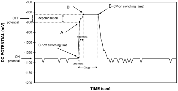
Typical Eon/Eoff waveform of cathodically protected PE coated pipeline when no capacitive AC mitigation devices are connected (U ac = 13·8 V)
Moreover, the instant Eoff measurement at the end of the 3 s CP-off time period can be simply performed using a hand held digital multimeter. On the contrary, the Eoff measurement at point A in Fig. 1 using a multimeter is prone to errors due to operator's subjective reading which is also dependent of the multimeter sampling rate.
Consequently, the suggested measurement of instant Eoff at prolonged time after switching is advantageous since both more reproducible results are obtained and the measurements are performed without using elaborate equipment.
In Fig. 2, a typical on/off pipe-to-soil potential waveform is depicted after the installation of the designed capacitive AC mitigation devices (AVACF). The waveform shape has been obviously modified (compared to that of Fig. 1) because it is now affected by the gradual discharging of the capacitive AC mitigation devices.
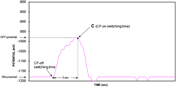
Typical Eon/Eoff waveform of cathodically protected PE coated pipeline when capacitive AC mitigation devices are connected (U ac = 1 V)
This phenomenon can be attributed to the following. The DC voltage between pipe and ground, charges every capacitive AC mitigation device. When the CP source is switched off, the AC mitigation devices behave like ideal capacitors and as a consequence start being discharged via earthing electrode/soil/pipeline. During this discharging process, usually lasting from <1 s up to few seconds depending on the discharge time constant τ, the capacitive AC mitigation devices act as a DC source supplying a decreasing with time cathodic current. This results to a negative IR drop which falsifies the Eoff value towards cathodic direction.
Instant Eoff values measured within the usual 1 s after CP-off switching, as the relevant standard dictates,17 could lead to the misconception that the pipeline is adequately cathodically protected even when it is not, unless the capacitive AC mitigation devices discharging currents are taken into consideration.
Up to the present, a common technique used to allow for the instant Eoff measurements, i.e. without the described Eoff readings falsification error, was by taking the measurements after the temporary disconnection of all of the capacitive AC mitigation devices from the pipeline. However, there are various disadvantages by this disconnection technique in the sense that the AC voltage is increased again to levels that may influence the CP potential readings4,8 and give rise to safety risks.
In addition, the disconnection and reconnection by the pipeline operation personnel is a time consuming process. A pipeline operator saves man hours when collecting cathodic protection data from the pipelines without having to manually disconnect the capacitive AC mitigation devices. Although for this reason an automatic system that disconnects the capacitive AC mitigation devices from the pipeline when a regularly pulsating on/off potential is sensed by an incorporated microprocessor has been designed and manufactured by others,11,12 the complicated electronics for this automatic disconnection may render it prone to malfunctions caused from overvoltage effects.14
All the above disadvantages are avoided when the measurement of the instant Eoff is taken at prolonged time after every CP-off switching, particularly under the condition that the capacitive discharging current from the capacitive AC mitigation devices is negligible, e.g. at the end of every 3 s CP-off period (point C in Fig. 2), as suggested by the present work. Otherwise the instant Eoff values may be falsified towards unrealistic cathodic values.
Additionally, the concept justifying the measurement of instant Eoff at prolonged time after CP-off switching is that the concentration overpotential, that is the prevailing one in CP, lasts very long (from hours to days) and is kept stable at least during the very first seconds of every CP-off period. Even in overprotection conditions, the activation overpotential from hydrogen evolution is usually lost in <100 ms,4 so that the usually measured Eoff between 0·1 and 1 s as suggested by standards17 is mainly due to the concentration overpotential. However, between 0·1 and 1 s, a depolarisation potential shift is usually obtained. This shift may be ascribed to another electrochemical process with slower activation overpotential than hydrogen evolution or to a process with at least mixed activation–diffusion control. Irrespective of its cause, it usually ends before the first second of the CP-off period giving rise to a <100 mV error. This error could be handled either as a tolerable systematic error, thus allowing the comparison of cathodic polarisation levels at various positions along the pipeline, or as a correction factor that can be used to approximate the true Eoff.
Proposed equivalent circuit of pipeline system with grounded capacitive AC mitigation devices
For the detailed analysis of the pipeline CP system response to the discharging effect of the capacitive AC mitigation devices during the periodic on/off switching of the cathodic protection circuit, an equivalent electric circuit representing a pipeline connected with grounded capacitors is proposed (Fig. 3a). In this equivalent circuit there are also elements, R uC u, in parallel, which are related to the buried pipeline. The R uC u circuit is further analysed (Fig. 3b) into parallel equivalent circuits which represent the n coating defects and the intact coated pipeline.
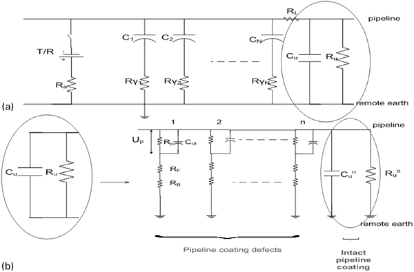
a equivalent circuit of cathodically protected buried pipeline connected with N capacitive AC mitigation devices and b equivalent circuit representing buried pipeline with n coating defects and intact coating
A number of N capacitive AC mitigation devices are connected to a pipeline of diameter D and length L. Each of them has a capacitance C i mF, where i = 1,2,3,…N. The resistance of the capacitive AC mitigation devices to DC is not presented in Fig. 3a, as it is almost infinite. When these capacitive AC mitigation devices are connected to a cathodically protected pipeline, they are charged by the DC current supplied by the CP transformer/rectifier (T/R unit), via a groundbed of a resistance to remote earth R a. As a consequence, a DC voltage appears at the terminals of every capacitive AC mitigation device. The value of this DC voltage usually ranges between 0·2 and 1·5 V. Additionally, each capacitive AC mitigation device is connected with a grounding electrode of a resistance to remote earth Rγ i.
During the CP maintenance measurements of a cathodically protected buried pipeline, the CP circuit is switched off and on periodically at typical on/off periods of 12/3 or 27/3 s. Owing to the aforementioned periodic switching, the DC voltage at the terminals of each i-capacitive AC mitigation device is instantly changed at the switching off moment and the capacitive AC mitigation device starts being discharged via the pipeline, the earth electrode and the soil.
As soon as the i-capacitive AC mitigation device is charged, the initial electric charge q i and the voltage ΔU i of every i-capacitive AC mitigation device at the end of each CP-on period are defined by the following equations


By switching off the CP current, the DC voltage at every i-capacitive AC mitigation device shifts instantly from ΔU i to ΔU i′ causing the beginning of every capacitive AC mitigation device discharging from its initial charge q i′ to a new charge q i′, expressed by the following equations


Calculation of time constant for discharging of capacitive AC mitigation devices connected to cathodically protected pipeline
The falsification of Eoff readings is related to the time constant τ of the capacitive AC mitigation devices discharging process during CP-off switching time. The longer is this time constant the larger the falsification of Eoff readings which are normally taken within the first second of CP-off period.
It is known that the discharge rate of a capacitor depends on the time constant τ of the circuit related to the pathway of the discharge current flow. The discharge current is flowing mainly through the two resistances R u and Rγ in Fig. 4 which, regarding the pathway of the capacitive discharge current flow, are actually connected in series. Consequently, the time constant τ for the simple case of discharging of one capacitive AC mitigation device earthed through a grounding resistance Rγ is given by

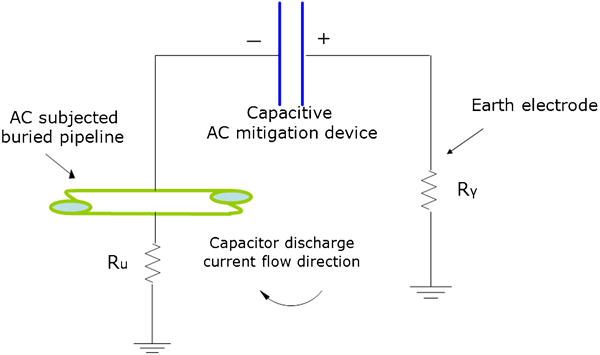
Schematic presentation of pathway of capacitive discharge current flow
In the case of N i-capacitive AC mitigation devices with capacitance C i each with grounding resistance Rγ i, the equivalent circuit is simplified to that of one capacitive AC mitigation device of capacitance  in series with a resistance
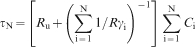
  , which has been proved, using the SPICE electric circuit analysis software.13 The time constant of the N i-capacitive AC mitigation devices discharging τ N is defined by the following equation, when the longitudinal resistance and capacitance of the pipeline is ignored

In the case that R u#Rγ and Rγ<<R u and specifically when N>>1, the time constant τ N″ becomes

In the previous calculations, the time constants corresponding to the total concentration polarisation have been ignored since that process is much slower than the capacitive AC mitigation devices discharging.13,16
Practical suggestions for control of time constant of capacitive AC mitigation devices discharging effect
For the elimination of the instant Eoff readings falsification, the time constant of the discharging effect of the capacitive AC mitigation devices τ is recommended to be <1 s. Then the discharging has practically been terminated before the end of every 3τ = 3 s CP-off period.
Supposing, τ<1 s, the relation (8) is transformed to


If


Inserting characteristic quantities in formula (13), i.e. if C = 5 mF and even in the unfavourable case of low pipe diameter, D = 0·2 m and high number of capacitive AC mitigation devices, N′ = 10−3 (i.e. one capacitor per km of pipeline) it results in r u<1·26×105 Ω m2 that is still within the common range (105–106 Ω m2) of coating resistivities for PE coated pipelines with few coating defects. This shows that inequality (14) could be practically valid even in well insulated pipelines, without having to implement further measures.
Considering the inequality (15), some measures to improve the falsification of the Eoff readings on a given pipeline earthed via capacitive AC mitigation devices are as follows:
decrease in the capacitance values C of the capacitive AC mitigation devices
decrease in the number N or the number per unit length N′ of the capacitive AC mitigation devices
decrease in the number of earthing sites N along the pipeline
lowering of the grounding resistance Rγ of earthing electrodes at the same earthing sites, e.g. by installing additional earthing electrodes and/or using earthing enhancing compounds18
decrease in the pipeline coating resistivity r u, through the installation of corrosion coupons.
Unfortunately the first three measures reduce the AC mitigation effectiveness thus leading to the necessity of compromising two opposite phenomena, the AC mitigation on the one hand and the minimisation of the error of the οff potential readings on the other. As a result, an optimisation of the parameters involved in these measures is essential. In addition, the optimisation of the number of earthing sites and AC mitigation devices, do not only favour the control of the falsification of Eoff readings but also provide a means of a cost effective AC mitigation.
On the contrary, the last two measures have the advantage of improving both the AC mitigation effectiveness and the Eoff readings falsification. Fortunately, in environments where the susceptibility to AC corrosion risk is higher, for instance in very conductive soils, low values of grounding resistances Rγ, are favoured, thus benefiting both the AC mitigation effectiveness and the control of the falsification of Eoff readings.
What additionally helps is an improved spatial distribution of the capacitive AC mitigation devices, by installing them at appropriate locations along the pipeline. For the choice of the most suitable installation sites, various data should be considered, e.g. soil resistivity data, measurements/recordings of AC voltage/current along pipeline, data from corrosion coupons/ER probes as well as data from the use of contemporary theoretical models for calculation of AC voltage profile19,20 which provide more realistic results of the AC interference level. Such an analysis of the key parameters optimisation for the reduction of the time constant of capacitive AC mitigation devices discharging effects is recommended to be incorporated in calculating software of the pipeline AC induced voltage profile. In this context, the theoretical models used for such calculations should be more sophisticated giving as accurate results as possible. Therefore, either an underdesign (e.g. insufficient number of earthing electrodes) or an overdesign (e.g. more grounding electrodes than necessary) could be avoided while the spatial distribution and grounding resistances of earthing electrodes could be optimised, enabling both an effective AC mitigation and a control of the Eoff readings falsification.
Moreover, the time constant of the capacitors discharging τ, can be controlled within certain limits by reduction of pipeline resistance to remote earth R u, via corrosion coupons, which additionally monitor the cathodic protection efficiency. Therefore, even in an unfavourable situation where a reduction of r u is necessary for the validity of inequality (14) or (15), it can be easily achieved by connection of few corrosion coupons to the pipeline. The coupons should be buried in a conductive environment so as to exhibit low spread resistance values. Their surface area should not be very large so that the cathodic protection effectiveness is not disturbed.
Alternatively, the instant Eoff readings might be taken at times longer than 3 s after switching, provided the depolarisation rate is slow in long term cathodically polarised PE coated pipelines.
Conclusions
In a cathodically protected pipeline during the periodic on/off switching of the cathodic protection circuit when the common technique of periodic switching of the CP circuit is used, the AC mitigation DC decoupling devices connected between pipeline and earthing electrodes tend to be discharged through pipeline and earth, creating capacitive discharging currents that falsify the instant Eoff values. This capacitive behaviour interferes with the acquisition of correct instant Eoff readings and therefore with reliable CP monitoring.
To study this phenomenon, the system of a well insulated pipeline with capacitive AC mitigation devices connected to earthing electrodes was simulated by an electric circuit and the role of the most crucial circuit elements was investigated.
The optimisation of the instant Eoff readings depends on the reduction of the time constant of capacitive discharge. One of the determining factors is the pipeline resistance to remote earth which depends on the number, the surface area and the spread resistance of the pipe coating defects. On most occasions, the pipeline resistance to remote earth is within acceptable limits. However, when a further reduction of the pipeline resistance value is necessary to minimise the falsification of instant Eoff readings, this could be easily achieved by installing additional buried corrosion coupons to the pipeline that also lead to a better monitoring of the cathodic protection efficiency.
Further ways of reducing the time constant of the capacitive discharging effect are the optimisation of the capacitance values as well as of the number of the AC mitigation devices along with the lowering of the grounding resistance of earthing electrodes. In addition, the reduction of the average earthing electrodes resistance to remote earth simultaneously by not increasing the number of earthing sites is advantageous both for the AC mitigation effectiveness and the control of the falsification of Eoff readings.
It is also suggested that the selection of the instant Eoff reading time to be at the end of every CP-off switching period (usually at 3 s) thus resulting to a systematic error that is generally lower than 100 mV. In this context, the instant Eoff readings can be reliable for CP monitoring without facing the undesirable disconnection of the capacitive AC mitigation devices. Having them connected is a great advantage since the induced AC voltage is kept low during CP measurements. As a result the AC interference adverse effects on the CP operation and monitoring are prevented.
The analysis of the factors which influence the error of instant Eoff measurements due to capacitive AC mitigation devices discharging currents should be included in the AC interference calculation software in order to optimise the conditions of AC mitigation of the pipeline via the capacitive AC mitigation DC decoupling devices.
Footnotes
Acknowledgements
Acknowledgements are given to Dr G. C. Christoforidis, (PhD El. Eng.), assistant professor of Technological Educational Institution of Western Macedonia, for his valuable assistance in the electrical circuit's transients.