
Abstract
Some 17 4PH propeller shafts showed severe localised corrosion after a long period of time in Ancona harbour. The shaft is concentrically mounted in an AISI 304 stern tube through two rubber bearings. Both 17 4PH and AISI 304 stainless steels were characterised by anodic polarisation in natural sea water, in order to obtain the necessary corrosion parameters for designing a suitable cathodic protection of the propeller system. The cathodic protection effectiveness was tested on a portion (about 1 m long) of this system. Two cathodic protection methods were tested: an impressed current cathodic protection at −0·3 V(SCE) and a galvanic cathodic protection. The tests were performed both in stagnant and in moving sea water and the results showed that these cathodic protection solutions were able to protect the propeller system; in particular some guidelines are suggested for both old and new ships.
Keywords
Introduction
The selection of metallic materials for marine applications is a crucial phase in ship design due to their exposure to sea water, characterised by high aggressiveness. Contemporarily, a metal with high mechanical strength is necessary for many purposes in the engines manufactured for the naval industry. A metallic material which has met these requirements is 17 4PH, a precipitation hardened stainless steel.1 – 5 This steel is a martensitic stainless steel containing nearly 3% of copper which is responsible, together with chromium, for this alloy hardening due to the precipitation of their compound rich phases,5,6 during an aging process performed in the temperature range of 480-600°C.1,2 Precipitation hardening is commonly performed after a solubilisation process at about 1000°C.
Some authors have observed localised corrosion phenomena in propeller shafts in AISI 316,7 which is another extensively used material in the naval industry. Other authors have compared, in sodium chloride solution, the corrosion properties of AISI 316 and 17 4PH stainless steels,8 obtained with powder injection moulding metallurgy. Both metals appeared to be interesting for the marine environment, although a tendency to pitting corrosion was found. The above authors also compared the localised corrosion properties of 17 4PH obtained both with this metallurgical technique and with the conventional metallurgical technique, in the same sodium chloride solution, observing a worse corrosion behaviour in the first case.5
17 4PH stainless steel can be subject to stress corrosion cracking in the presence of both hydrogen gas generation (producing hydrogen embrittlement, as is the case for many high strength steels in these conditions) and exposure to sea water, in which the failure of the propeller shaft was analysed.6 The possible influence on this steel of molybdenum content and of aging treatment conditions has been studied in order to identify alloys with better mechanical and corrosion performance.2
In this work, the localised corrosion phenomena observed on the 17 4PH propeller shafts of a yacht berthed in Ancona harbour are investigated and a possible cathodic protection solution is suggested. In particular, many points of pitting corrosion and specific zones of crevice corrosion were found on the shaft surface. Crevice corrosion attack was found in correspondence with the rubber bearings separating the propeller shaft and the AISI 304 stern tube.
Failure was not observed. However, although the pits present on the 17 4PH propeller shaft are, at first sight, relatively small, an in-depth analysis shows that, from the surface, the corrosion continues inside the material in a cavernous way, producing a reduction in the resistant cross-section of the shaft. This phenomenon may lead to propeller shaft failure. Therefore, in order to prevent this problem, anodic characterisation was performed both for 17 4PH and for AISI 304 and a method for cathodic protection (impressed current and galvanic coupling approaches) is suggested to stop the process of corrosion in old ships and to prevent it in new ones. The experimentation was carried out using sea water collected from Ancona harbour.
Experimental procedure
A preliminary visual inspection of the localised corrosion phenomena found on the 17 4PH shaft was carried out.
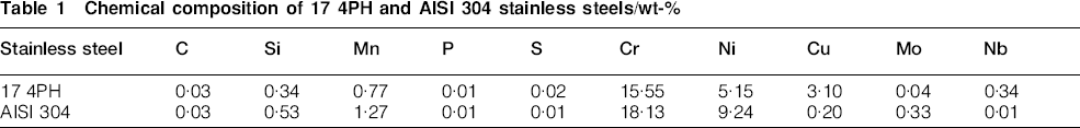
The propeller shaft and stern tube steels were chemically characterised using a Spark Analyzer SPECTROLAB Mod. LAVFA A18A (Table 1).
Chemical composition of 17 4PH and AISI 304 stainless steels/wt-%
Their electrochemical characterisation was carried out by anodic polarisation in Adriatic sea water, collected from Ancona harbour, in the summer time. The salinity is 39 g L−1 and considering the average temperature of the surface sea water at this time of the year, the concentration of O2 is approximately 7-8 ppm.9,10
Anodic polarisation curves were recorded at 25±1°C using a three-electrode configuration cell: the stainless steel samples (working electrodes) had an exposed area of 3·14 cm2; two platinum sheets, connected together, were used as counter electrodes; a saturated calomel electrode (SCE) was used as a reference electrode.
The polarisation curves were obtained by means of the potentiostat AMEL Mod. 2059 managed by the National Instruments PXI-6120 module and by a suitable software developed in NI LabWindows/CVI 7.0. Before the tests, the free corrosion potential E corr was monitored until it reached a stationary value. The ohmic drop correction of the anodic curve was not taken into account, considering the very high conductivity of the sea water. The potentiodynamic scans were carried out with the following criteria: starting potential E corr –30 mV; scan rate 0·166 mV s−1; direct anodic polarisation up to a current density threshold of 0·1 mA cm−2; reverse sweep until new passivity conditions were obtained, when possible. Otherwise, the polarisation was stopped when the initial corrosion potential was reached. All the anodic curves were recorded in triplicate to check their repeatability. From these curves, the average values of the pitting, protection and corrosion potentials were determined and indicated respectively as E pit, E prot and E corr.
The polarisation tests were carried out both in stagnant and in moving sea water by means of a magnetic stirrer set in the range 1000-1500 rev min−1 in order to simulate the condition of the ship when stationary in the harbour and in navigation at sea respectively.
The cathodic protection tests were performed with a reduced version of the real system constructed using a portion of the propeller shaft, 102 cm long and with 11 cm diameter, and a portion of the stern tube 88 cm long, with an internal diameter of 17 cm. These two parts were assembled together by means of two polyvinyl chloride flanges as schematically shown in Fig. 1. Therefore, the length of both components in contact with the sea water was 88 cm corresponding to a surface of 3041 cm2 for the shaft and to an internal surface of 4700 cm2 for the stern tube. Between the shaft and the tube there was an interspace, containing about 12 L of sea water.
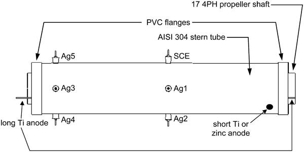
Schematic corresponding to the top view of the reduced version of the real system: it is made up of a portion of the propeller shaft and a portion of the stern tube, assembled together with two PVC flanges; although the anodes are all shown here, they were used separately in different experimental sessions; Agi: Ag/AgCl/KCl sat. electrode, i = 1, 2, …, 5
In order to evaluate the effectiveness of cathodic protection in all experimental conditions, six reference electrodes were initially manufactured in the laboratory: five easy to use Ag/AgCl/KCl sat. electrodes [potential range −35 to −45 V(SCE)]; one SCE with a long plastic capillary tube. These were all installed on the studied system (Fig. 1). During data elaboration, all the measurements were reported with respect to the SCE reference potential.
The first and the second experiments were carried out using impressed current cathodic protection, with a long activated Ti anode and a short Ti activated anode respectively (Fig. 1): the former (φ0·3 cm, length 88 cm for a total surface of 83 cm2) was placed lengthwise in the interspace, while the latter (φ0·2 cm, length 4·8 cm for a total surface of 3 cm2) was positioned only at one end of the studied system. The water was both stagnant and in movement due to a pump in series with a reservoir in a loop circuit; the pump provided flow of 8-10 L min−1 through the interspace. In these dynamic conditions, the Ag4 electrode (Fig. 1) was removed and substituted with the water inlet, while the water outlet was very close to the position of the short Ti in Fig. 1 (not shown in the schematic).
The third experiment was the analysis of cathodic protection performed with a cylindrical zinc anode (φ3·3 cm, height 4·4 cm for a total active surface of 54 cm2) which is quite good for protecting steel in sea water.11 The chemical composition of this anode was determined by dissolving known amounts in aqueous solutions, which were subsequently examined using inductively coupled plasma spectroscopy. This analysis shows that the anode composition corresponds to data reported in the literature, with 0·39 wt-% aluminium, 0·044 wt-% cadmium and only traces of other elements.11 During this final experiment, the water was kept stagnant.
The tests relative to the impressed current cathodic protection were performed by means of an AMEL 2055 potentiostat, connecting both the propeller shaft and the stern tube (short circuited together) as a working electrode, the SCE as a reference electrode and the Ti anode as a counter electrode. The protection potential was set with respect to SCE. In the experiment of galvanic protection with a zinc anode, the potentiostat was used as a ‘Zero Resistance Ammeter’ keeping the potential between the working electrode and the counter electrode (short circuited with the reference connection), at 0·0 V. In both cases, the I out BNC connector of the potentiostat was used to measure the cathodic protection current.
Throughout the tests, the circuit current and the potential of the 17 4PH propeller shaft, with respect to the Ag/AgCl electrodes and with respect to SCE, were continuously monitored by means of an Agilent Data Switching Unit Mod. 34970A, with a multiplexer module 34901A, connected to a PC by an RS-232 port.
Results and discussion
Figure 2 shows two propeller shafts with widespread pitting which may lead to serious problems, particularly when there is deep propagation of the localised corrosion with subsurface progression as shown in Fig. 3.12 This phenomenon considerably reduces the mechanical strength of the 17 4PH propeller shaft.
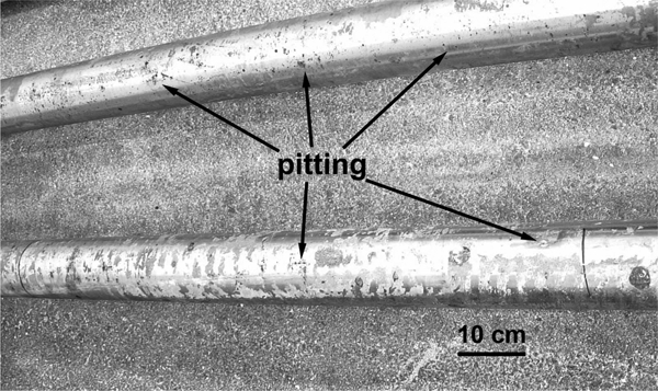
Pictures of two propeller shafts with several points of localised attack
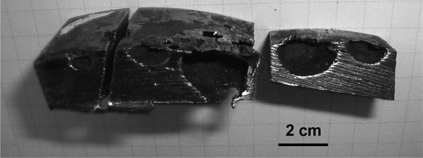
Cross-sections of some pieces of propeller shaft showing dramatic progress of pitting corrosion
Figures 4 and 5 show two representative anodic curves, obtained respectively on AISI 304 samples and on 17 4PH samples in both stagnant and moving water. Instead, Fig. 6 shows the histogram representing the average values obtained from the potentiodynamic experiments for both materials. This figure highlights the perfect passivation zone between the protection potential E prot and the corrosion potential E corr and the imperfect passivation zone between the pitting potential E pit and the protection potential.13 From the results obtained, 17 4PH is more susceptible to pitting corrosion than AISI 304 stainless steel, both in stagnant and in moving sea water. These results are in agreement with those reported in the literature. In more detail, the corrosion potential and pitting potential respectively, around −0·200 and 0·250 V(SCE), for AISI 304, are similar to the values found for this steel in 3·5 wt-% NaCl;14 even in the case of 17 4PH, the corrosion potential [around −0·250 V(SCE)] and pitting potential [around 0·050 V(SCE)] are close to the corresponding values obtained for powder injection moulded 17 4PH in 3 wt-% NaCl, while, in this case, the protection potential is higher than the value reported in the literature.5

Anodic curves of two AISI 304 samples of stern tube in stagnant () and moving  ) sea water
Anodic curves of two 17 4PH samples of propeller shaft in stagnant () and moving () sea water

Histogram representation of average pitting, protection and corrosion potentials obtained from potentiodynamic tests for AISI 304 and 17 4PH both in stagnant and moving sea water: this plot shows in detail perfect passivation zone () and imperfect passivation zone ( )
)
Moving sea water has only a slight influence on the anodic characteristics of both stainless steels (Fig. 6).
From the electrochemical test results, it was possible to choose the protection potential for cathodic protection performed using the impressed current method. From a theoretical point of view, the protection potential can be set at values slightly lower than the E prot determined by the anodic characteristics of the material,15 which can be reduced to enhance the formation of a protective calcareous layer on the metal surface. Therefore, a potential value of −0·3 V(SCE), well under the lowest E prot measured (Fig. 6), was chosen. This value is a little less than the observed corrosion potential.
Figures 7–10 show potential and current trends during the cathodic protection tests. On the right, these figures show, for each curve, the corresponding ‘exploded lines’ which improve the readability of the experimental data.
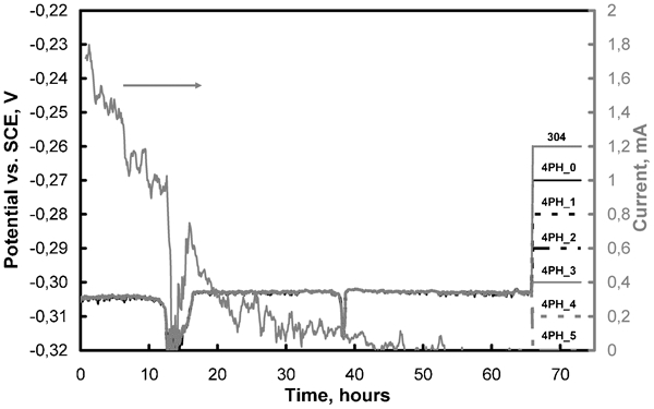
Potential and current trends measured during cathodic protection test performed in stagnant sea water with long activated Ti at protection potential of −0·3 V(SCE) (‘304’ corresponds to potential trend of AISI 304 stern tube versus SCE, while 4PH_i represents potential trends of 17 4PH propeller shaft measured with respect to electrodes Agi in Fig. 1; in particular, 4PH_0 is potential versus SCE)
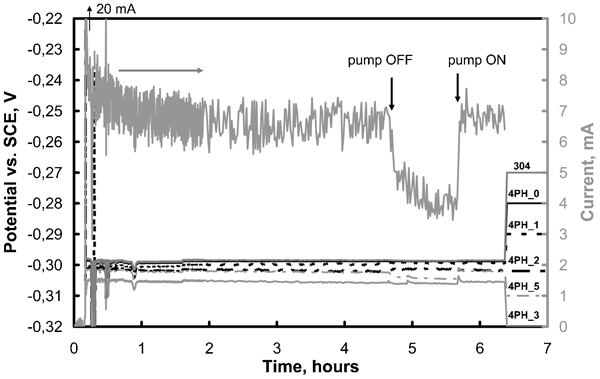
Potential and current trends measured during cathodic protection test performed in moving sea water with long activated Ti at protection potential of −0·3 V(SCE) (‘304’ corresponds to potential trend of AISI 304 stern tube versus SCE, while 4PH_i represents potential trends of 17 4PH propeller shaft measured with respect to electrodes Agi in Fig. 1; in particular, 4PH_0 is potential versus SCE): temporary switching-off of pump is shown
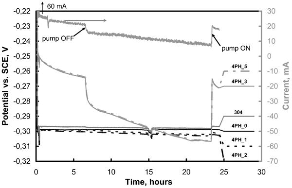
Potential and current trends measured during cathodic protection test performed in moving sea water with short activated Ti at protection potential of −0·3 V(SCE) (‘304’ corresponds to potential trend of AISI 304 stern tube versus SCE, while 4PH_i represents potential trends of 17 4PH propeller shaft measured with respect to electrodes Agi in Fig. 1; in particular, 4PH_0 is potential versus SCE): temporary switching-off of pump is shown
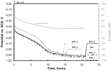
Potential and current trends measured during cathodic protection test performed in stagnant sea water with zinc anode (‘304’ corresponds to potential trend of AISI 304 stern tube versus SCE, while 4PH_i represents potential trends of 17 4PH propeller shaft measured with respect to Agi electrodes in Fig. 1; in particular, 4PH_0 is potential versus SCE)
The effectiveness of the impressed current cathodic protection performed with the long Ti anode can be inferred from Fig. 7, apart from some anomalous negative spikes. All potential curves were completely superposed indicating a homogeneous electric field produced by the Ti anode in the whole propeller shaft stern tube system. Figure 7 shows that, in general, the current was quite low (under 2 mA, which corresponds to 2·6 mA m−2 taking into account that 0·77 m2 is the total active surface of the protected system) and therefore, a great quantity of electrical energy is not required to implement cathodic protection. The decrease in current is due to the reduction in the concentration of oxygen in stagnant sea water, because it is gradually consumed by the cathodic protection. Considering that scale formation was observed on the propeller shaft, the decrease in current could partially be attributed to the increase in its surface impedance.
On pumping water in the interspace, after removing the Ag4 reference electrode, the initial current peak reaches a value of 20 mA (Fig. 8). Once again, a decrease in current follows this peak and a quasistationary state is achieved, corresponding to an average value of about 7 mA (9·1 mA m−2). After turning off the pump, the current first decreased abruptly and then gradually. The reactivation of the pump brings the current back to its previous stationary value. This can be explained considering the change in the oxygen limiting diffusion current density in sea water, passing from dynamic to stagnant conditions. Furthermore, in dynamic conditions, the oxygen consumed by the cathodic protection is continuously renewed and therefore, its concentration does not significantly change with respect to the test time, producing a quasi-stationary protection current. Finally, dynamic conditions produce an increase in ionic conductivity determining a better protection of all parts of the system.
The high current values found during this experiment lead to a separation between the different potential curves, albeit within 0·1 V (Fig. 8). In particular, more negative potentials were recorded by the Ag3 and Ag5 electrodes (4PH_3 and 4PH_5 trends) corresponding to a higher polarisation effect on these points with respect to the others. Such an effect can be explained by considering that these two points are very close to the sea water inlet (the same position as Ag4 in Fig. 1), where there is a turbulent flow enhancing the ionic conductivity and therefore, a higher polarisation effect.
When the short activated titanium was used instead of the long one (Fig. 9), considerably higher currents were measured due to a less homogeneous electric field determined by this anode which has a ‘local nature’ in the studied system. Starting from a peak of 60 mA, the current decreased to a quasi-stationary value of 20 mA (26·0 mA m−2). A first significant current decrease and a second gradual current decrease were observed when the pump was switched off, which determined the progressive consumption of the oxygen dissolved in the water. In dynamic conditions, the effect of the water turbulent flow on the higher polarisation in correspondence with Ag3 and Ag5, previously observed, is less important than the effect produced by the local nature of the electric field determined by this short anode. In fact, it is positioned at the opposite end of the stern tube with respect to Ag3 and Ag5 (Fig. 1), where potentials 4PH_3 and 4PH_5 were measured respectively; therefore, these electrodes experienced a lower polarisation effect produced by this short Ti anode. On the contrary, a higher polarisation effect was found for the closer Ag2 and Ag1 electrodes (4PH_2 and 4PH_1 trends) as can be observed in Fig. 9. Apart from these polarisation effects, throughout the experimentation, all the potential values were well under the lowest protection potential previously considered (Fig. 6) for setting the best conditions of impressed current cathodic protection. In conclusion, the short Ti anode is able to protect the propeller shaft and stern tube, even if it provides a less homogeneous electric field.
Some experiments were performed separately with both previous anodes (results not reported here) bringing the protection potential to −0·9 V(SCE) in order to maintain all the metallic parts in conditions of immunity from corrosion. However, the results showed that these conditions must not be recommended for three important reasons: (1) the currents necessary to reach this potential are too high; (2) there is a huge production of chlorine at the anode which is an undesired phenomenon; and (3) there is the thermodynamic possibility of hydrogen evolution in the protected metallic parts. This final phenomenon can be particularly dangerous for the 17 PH propeller shaft, because it is a high strength steel and therefore, susceptible to hydrogen embrittlement.
Figure 10 shows the results of the final experiment performed using a zinc anode for the cathodic protection of the propeller system in stagnant sea water. Taking into account that this anode produces an electric field of a ‘local nature’, similar to the short Ti anode, even in this case, less polarisation was observed in correspondence with Ag3 and Ag5 (4PH_3 and 4PH_5 trends) due to their great distance from the anode. At the beginning, a considerably high current was measured (95 mA) followed by a gradual decrease to about 15 mA (19·5 mA m−2); at the same time, the potential values went down to −0·9 V showing that with a zinc anode, immunity conditions can be achieved, although there is a possible problem of hydrogen evolution. On the basis of these conclusions, for the moment it is advisable to exclude the use of a zinc anode for the system subjected to the present investigation.
In conclusion, the best way to protect the studied system from localised corrosion phenomena is to apply the impressed current cathodic protection by means of Ti activated anodes. In particular, a long Ti, positioned along the interspace between the propeller shaft and the stern tube, can be used for new ships because the installation is much easier in this case, providing suitable housing for it. On the contrary, the installation of a short Ti can be more practical for old ships. In this latter case, two anodes can be placed on the stern tube walls with the active surface towards the interspace, with a distance of 2l min between each other, where l min is the minimal distance for ensuring the effectiveness of the cathodic protection. Taking into account that in the laboratory version of the system, the cathodic protection was effective for the whole stern tube length, l min can be set equal to 88 cm, and hence, the distance between the two short Ti anodes can be twice this length, 176 cm. In more detail, the anodes can be placed at this distance and also at equal distances from the real stern tube extremities (about 3 m long). Furthermore, if the laboratory version of the system is about 3·4 times smaller than the real one and if a maximum of 20 mA was necessary to maintain the potential at −0·3 V(SCE) with moving sea water (Fig. 9), as considered above, 70 mA (once again corresponding to 26·0 mA m−2) can be sufficient for the real system. This can easily be managed with the use of an electrical device which is able both to provide this current and to work with a reference electrode.
Concerning the protection potential, values under −0·3 V are not necessary, while values which are more positive than this potential can be considered. In this case, attention must be paid to the zones where the potential becomes necessarily higher than the set one, as is the case for the points measured by the Ag3 and Ag5 reference electrodes (Fig. 9), which are far from the short Ti anode. These zones are less polarised and in some particular conditions, where the set potential is not sufficiently low, they may have values above E prot. In these cases (imperfect passivity conditions), the risk of corrosion propagation exists, if, for example, the stainless steel passivation film is mechanically damaged by an accidental event.
Conclusions
In this work, localised corrosion observed on a ship propeller shaft stern tube system was studied. Initially, the anodic characteristics of the metallic materials were obtained in sea water and subsequently, some cathodic protection strategies were experimented, leading to the following conclusions:
Potentiodynamic tests indicate that the 17 4PH propeller shaft is more susceptible to pitting corrosion than the AISI 304 stern tube. On the basis of these tests, −0·3 V(SCE) was the potential chosen for cathodic protection experiments using the impressed current method.
Tests of cathodic protection performed by imposing a current with Ti anodes showed that the value of −0·3 V(SCE) was a protection potential suitable for the studied system, because it holds its metallic parts in the perfect passivity region. If a potential relative to the immunity conditions [−0·9 V(SCE)] is set for cathodic protection, there are possible problems of hydrogen embrittlelment of 17 4PH, the requested current to supply is too high and chlorine is produced at the anode. Therefore, achieving immunity conditions is neither necessary nor suggested.
Considering that both short activated Ti and long activated Ti anodes are able to protect the propeller shaft stern tube system by supplying the necessary current, the former appears more suitable for old ships, installing two anodes at 176 cm from each other, at an equal distance from the stern tube extremities, while the latter, giving a more homogeneous electric field, can be destined to new ships.
A zinc anode was also tested in order to apply a galvanic cathodic protection. This anode is good for protecting the whole system, but the potential of −0·9 V(SCE) is reached in stagnant water and therefore, the risk of 17 4PH hydrogen embrittlement can be present.