
Abstract
In the present study, the influence of processing parameters of friction stir welding on the corrosion rate of the welded joints of aluminium SiC–Gr hybrid composites was investigated. The experimental results indicate that the corrosion resistance of the welded joints increases at high welding (traverse) speed and/or low values of rotational speed. These variations occur as a result of the changes in the joint microstructure, where fine grains are developed as a consequence of a relatively low heat input and fast cooling to room temperature by ambient air associated with low rotational speed and/or high welding speeds. The mixed electrode theory is used to explain these variations of the corrosion rate, where the area ratio of cathode/anode for the galvanic couple between the aluminium metal matrix and the reinforcement constituents becomes small for fine grains. Thus, the corrosion resistance of the welded joints is increased.
Introduction
Aluminium matrix composites (AMCs) are extensively used in many structural and industrial applications in marine, aerospace, automotive and defense sectors due to their outstanding attractive properties.1 – 5 They have high strength/weight ratio, as well as good wear and abrasion resistance and controlled thermal expansion coefficient.2,5
The joining of components made from AMCs is still limited due to the challenges and the limitations associated with the conventional fusion welding techniques, including the occluded gas evolution, interfacial reaction between reinforcement and the molten matrix composite, the non-homogeneous distribution of reinforcement and the presence of inclusions.6,7
Friction stir welding (FSW) is a technique that allows welding of aluminium alloys that are not possible to be welded using the traditional fusion welding methods.8 – 10 Friction stir welding exploits the heat generated by friction between a non-consumable tool and the substrate intended to be joined, in combination with forging pressure to produce high strength bond. The material is transformed from a solid state into a softened state by heating action around the tool, and the forging pressure will cause the material to flow from the front of the tool to the back (mechanical stirring) to form a high integrity welded joint.11
Friction stir welding is an eco-friendly process with no toxic fumes generated, and there is no need for any shielding gas.12,13 The welding is carried out at temperature below the melting temperature, and thus, the distortion is minimal and the properties of the material in the joined area are superior from any other welding process with a fine grained microstructure.14 – 16 A limited number of process variables can be controlled, such as rotational speed, traverse speed and tool geometry, which causes a significant reduction in the process variability. This reduction combined with the superior strength of the joint provides a high degree of reliability and increases the safety margin.17
The corrosion behaviour of AMCs has been extensively studied. From these studies, it is recognised that the corrosion of AMCs is determined by several factors, including the composition of the composite, the matrix microstructure, the type and the shape of the reinforcement, its distribution in the matrix material, the nature of the interface between matrix and reinforcement and the processing technique that is used to create the composite.18 – 20 The type of the dispersed reinforcement plays an important role in determining the corrosion mechanism in these materials. For example, when the aluminium matrix is reinforced with SiC or graphite, a galvanic couple forms between the active metal and the noble reinforcement that act as a site for cathodic half cell reaction. The strength of this galvanic couple depends mainly on the type and the thermal conductivity of the reinforcing constituents; therefore, AMCs reinforced with SiC or graphite have higher corrosion rate in comparison to their monolithic matrix alloy. On the other hand, AMCs that are reinforced with Al2O3 particles or fibres are unlikely to form a galvanic couple because of the high resistivity of Al2O3, and thus, they show better corrosion resistance in comparison to the monolithic matrix.21 – 26
As a result of the nature of the FSW process, where a relatively high temperature is being generated by the friction between the tool and the workpiece, the stirring and the deforming actions of the rotating welding tool, the structure of the weld zone is expected to be different from the structure of the unaffected base compocast base metal plates.
Moreover, the temperature increase in the nugget zone during FSW affects greatly on the microstructure of the precipitation hardened alloys. For example, in Al–Mg–SiC alloys, some precipitates will be metastable and dissolve to produce Mg and Si super saturated solutions; other precipitates will survive the decomposition stage and get coarser. These microstructural changes impact on the mechanical properties of the weld and cause a dramatic loss of the hardness in the nugget zone. In Al–Mg–Sc alloy, the precipitates are not affected by the temperature rise in the nugget zone, and they can sustain their stability, which makes the decrease in nugget zone hardness smaller than what is observed in Al–Mg–SiC alloys. In addition, these precipitates may interact with grain boundaries and recrystallised grains, hindering their growth. Thus, finer grain sizes are formed in Al–Mg–Sc alloy.27 These structural changes in the nugget zone affect on the various characteristics of the welding as wear resistance and hardness.28,29 This paper discusses the effect of these changes on the corrosion characteristics of the weld nugget zone.
Few papers have been published on corrosion of FSW joints of aluminium alloys, i.e. AA 2024 and AA 7010.30 – 34 These papers indicate explicitly that FSW weld joints are exhibiting different corrosion behaviour than the base compocast plates. The published literature on the corrosion of the friction stir welded metal matrix composite (MMC) is rather limited, and there is a lack of information on the susceptibility of FSW joints to corrosion. In this study, the influence of the FSW process parameters (pin tool profile, welding speed and rotational speed) on the corrosion rate of the FSW joint of hybrid AMCs that is reinforced by a combination of two kinds of ceramic particles (SiC and graphite) in 1·0M HCl solution has been investigated. Hydrochloric acid is used, in the present study, for this corrosion tests because it is one of the most commonly used acids in the periodic cleaning of the metallic surfaces of alloys used in domestic and industrial practices that involves exposure to water, where scales and corrosion products have high potentials to form and deposit on the metallic surface, affecting negatively on heat transfer.35 In addition to that, the pH of the water stream in many industrial processes, i.e. food processing, pharmaceutical and drinking waters, is controlled using hydrochloric acid.36
Experimental
Cast plates (100×75×7·5 mm) of AMC (Al–4 wt-%Mg, reinforced with 1 wt-%SiC–1 wt-% graphite particles) were produced using the compocasting technique. Magnesium was used as a wetting agent. The SiC and graphite particles were used as reinforcement to the matrix. The nominal chemical composition of the aluminium matrix is listed in Table 1. The AMCs were prepared by melting commercially aluminium matrix in a graphite crucible using an electric furnace to heat the aluminium to a temperature of 900°C. The reinforcements are small particles of SiC, and graphite were wrapped in aluminium foils, preheated and added to the molten aluminium and stirred continuously. Mechanical agitation with the aid of a stirring blade is used to mix the constituents of the composite in the liquid and the semisolid state to ensure a uniform distribution of reinforcement material within the matrix. The stir caster is driven by a motor. The stirrer geometry, position and speed are selected with the aid of previous studies.37 – 39
Chemical composition of matrix/wt-%

In addition, the magnesium was wrapped inside an aluminium foil, preheated and added to the molten composites and then stirred for a period of 3 min while the furnace is off. After stirring, the molten composite was poured inside a permanent stainless steel mould at a temperature between 600 and 700°C during pouring and left to solidify to room temperature. After solidification, the specimens were annealed at a temperature of 400°C for a period of 2 h to remove the residual thermal stresses induced during the casting process of the plates.40
The plates were butt friction stir welded using a conventional milling machine with the welding tool in the milling machine spindle and the plates secured to the milling table. The working parameters used for FSW are shown in Table 2. Samples to be used in the corrosion test were cut from the friction stir welded nugget zones with lengths of 25 mm in the welding direction and 20 mm in the transverse direction. Then, these samples were ground with emery paper 800 and 1200 grit size and washed with water and alcohol to get rid off any left contamination.
Process parameters of friction stir welding
The effects of the FSW processing parameters, tool pin profile, rotational speed and welding (traverse) speed on corrosion rate of the welded zone were studied. The working range of the welding and rotational speeds is selected so that it covers the operational range of the machine. Moreover, the selected ranges of the welding and rotational speeds are consistent with these used by other researchers.41,42 The authors also studied the effect of the tool pin profile on the FSW joints of AMCs, and they reported the results somewhere else.43 First, the effect of the tool geometry was studied using three different profiles for the pin tool (square, hexagonal and octagonal). For each profile, four (traverse) welding speeds were used, and at each welding speed, four different rotational speeds were examined. Lower corrosion rate was obtained with square head pin tool. Accordingly, this type of pin tool was used to study the influence of the rotational speed and the welding speed on the corrosion rate of the welded nugget zones of the considered composite.
Immersion testing in a solution of 1·0M HCl (37% concentration) at 23-25°C temperature range for 90 min was used to study the susceptibility to corrosion according to ASTM G31 standards. The mass of each sample was measured before and after the immersion, and the mass loss due to the exposure to the corrosive environment is used to compute the corrosion rate (mm/year) according to Faraday's law,44 as indicated in equation (1)
All corrosion rates that are presented in this paper are the mean value for four measurements, with a standard deviation of a range 3-9 mm/year. These corrosion rates were presented in the master's dissertation work by Ghaithan45 and used in this paper in order to analyse the variations of the corrosion rates using the mixed potential theory.
Results
Influence of tool geometry on corrosion behaviour
The effect of the tool pin profile on the corrosion rate of the welded zone of the considered composite was investigated while varying both rotational and welding speeds. For each tool profile, the corrosion rate was measured at different welding speeds while maintaining the rotational speed constant, and then the entire set of tests was repeated at other values of the rotational speeds. In Figs. 1–4, the horizontal line represents the nominal value of the corrosion rate for the parent plate (as cast base AMCs), whereas each point on the intermediate curves represents the mean value for four measurements at particular welding conditions. All the examined tool profiles show that the corrosion rate decreases with increase in the welding (traverse) speed and/or decrease in the rotational speed, as can be seen in Figs. 1 and 2. However, as it has been mentioned earlier, the square pin profile tool exhibits the lowest corrosion rate; the hexagonal pin profile tool shows intermediate values for the corrosion rate, whereas the octagonal pin profile shows the highest corrosion rate.
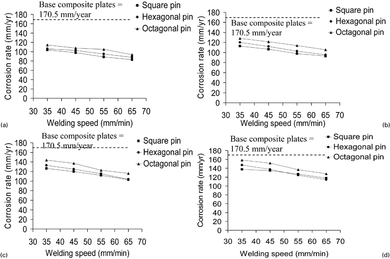
Corrosion rate (mm/year) versus welding (traverse) speeds (mm min−1) at different rotational speeds
Corrosion rate (mm/year) versus rotational speeds (mm min−1) at different welding (traverse) speeds
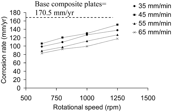
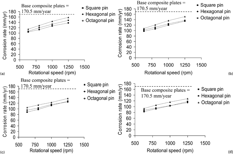
Corrosion rate (mm/year) versus tool rotational speeds (rev min−1) at different welding speeds
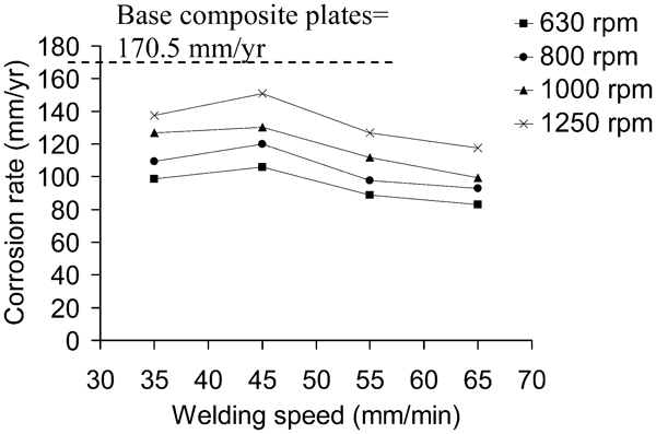
Corrosion rate (mm/year) versus welding (traverse) speeds (mm min−1) at different rotational speeds
Influence of rotational speed on corrosion behaviour
Figure 3 shows the influence of the rotational speed on the corrosion rate of friction stir welded joints of the considered composites. The plot of the results obtained from the immersion test shows that the corrosion resistance for the welded joints increases as the rotational speed decreases at all of the examined welding speeds. These results obtained using hybrid composites are consistent with the previous studies, i.e. Wadeson et al. and Song et al. found that alloys with fine grains have generally superior corrosion resistance as compared to those containing coarse grains.46,47
Influence of welding (traverse) speed on corrosion behaviour
The corrosion rates at different levels of welding (traverse) speed using the square pin profile tool are shown in Fig. 4. At lower welding speeds of 35-45 mm min−1, the corrosion rate increased because the associated generated heat during friction welding is not sufficient to cause reduction in the grain size to a degree that increases corrosion resistance. Whereas, for speeds >45 mm min−1, the heat developed during welding is enough to cause formation of fine grain size to the level, which causes an increases in the corrosion resistance.
Discussion
It was stated in the literature that the grains’ size has a great effect on the physical properties of the friction stir welded nugget zones.46 – 48 Hence, in smaller grain size structure, better physical properties are encountered, in contrast to coarse grain structure.
Tool pin profile
In FSW, the tool pin profile has an effect on the properties of the joint owing to the fact that a large portion of the developed heat during the welding process came from the tool shoulder, and the pin has a high influence on the plasticising of material. The experimental results demonstrate that weld joints produced using the square pin profile have the lowest corrosion rate. These results can be attributed to the smallest contact area of the square pin as compared to octagonal or hexagonal, drawn inside the same circle. The contact area between the tool and the specimen results in different heat generation within the specimen. When the heat is rather high, faster cooling rate to ambient temperature is achieved, which leads to a small grain size and causes a reduction in the area ratio of cathode/anode, increasing the resistance against uniform corrosion, as discussed in the next section. The microstructures of the welded joints developed by different considered tool pin profiles are shown in Fig. 5.
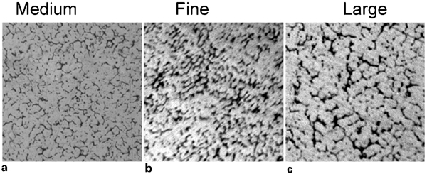
Effect of tool pin profiles on FSW zone microstructure using a hexagonal, b square and c octagonal pin profile tools at rotational speed of 800 rev min−1 and welding (traverse) speed of 55 mm min−1, ×500
Rotational speed
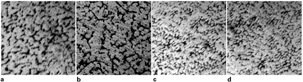
The microstructure of the nugget zone is significantly influenced by the rotational speed of the tool. The stirring and mixing of the material around the pin profile during the FSW increase with the increase in welding tool rotational speed, which leads to a high heat input. The increase in the temperature that accompanies the increase in the rotational speed causes the grain size growth, and thus, larger grain size will be formed,49 when the weld is cooled to room temperature. Hence, the area ratio of cathode/anode for the formed galvanic couple increases, which results in reduction in the corrosion resistance of the welded joint. The microstructural changes of the welded joints developed with variation of the rotational speeds are shown in Fig. 6.
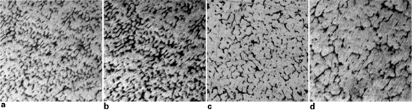
Effect of rotational speed on zone microstructure at rotational speeds of a 630, b 800, c 1000 and d 1250 rev min−1 and welding (transverse) speed of 55 mm min−1, ×500
Welding (traverse) speed
As the welding speed increases at a constant rotational speed, the contact time between the tool and the welded material becomes shorter; this results in a relatively lower heat input and a fast cooling rate by ambient air. Therefore, the grain size decreases, as there is not enough time for the growth of the grains with the increase in the welding speed.50 The formation of the fine grains reduces the area ratio of cathode/anode in the developed galvanic couple of the produced composite, thus reducing the corrosion rate of the friction stir welded nugget zones at higher welding speed. The microstructural changes of the welded joint developed with welding speeds are shown in Fig. 7.
Effect of welding (transverse) speed on zone microstructure at welding (traverse) speed of a 35, b 45, c 55 and d 65 mm min−1 and rotational speed of 800 rev min−1, ×500
Corrosion mechanism
The literature on the corrosion behaviour of the MMCs has shown that lower corrosion resistance of the MMC reinforced with conductive or semiconductive particles in comparison to their monolithic matrix alloys.51 Galvanic corrosion is blamed for the high corrosion rate of MMCs, where a galvanic couple will form between the metal matrix and the reinforcement constituents.52
After immersion of the aluminium SiC–Gr hybrid composite sample in HCl solution, a series of electrochemical reactions takes place; anodic and cathodic reactions occur simultaneously. The anodic dissolution of aluminium results in aluminium cations in the solution by the half cell reaction

Based on the mixed electrode theory, in a galvanic couple, the cathodic current I c is equal to anodic current I a.52 Both cathodic and anodic current can be written as

Equation (7) can be rewritten as

As equation (8) implies, the anodic dissolution rate i a and, thus, the galvanic corrosion rate i GALV depend on the value of the area ratio α. The smaller the value of α will result in a decrease in the dissolution rate and, thus, a higher corrosion resistance. One way to attain small α is achieved by having small cathodic area. The size and the distribution of the reinforcement particles in the parent material (the as cast AMCs) are different from their sizes and distributions in the nugget zone. For the as cast AMCs, the reinforcement particles form clusters imbedded in the matrix. After the FSW, and as a result of the severe plastic deformation, and material stirring, the size of the reinforcement particles decreased in the nugget zone, the number of fine particles increases, the particle clusters broke up and their distribution becomes more homogeneous. These phenomena have been observed in many FSW discontinuously reinforced metal matrix composites. Hence, this effect of FSW on the size of the reinforcement particles reduces the cathodic area and, thus, the area ratio leading to small galvanic corrosion rate. Another way to minimise α is by reducing both cathodic and anodic areas, which can be attained by forming fine grains. For the FSW of aluminium SiC–Gr hybrid composites, the finest grains are obtained upon using the square tool profile, increasing welding (traverse) speeds or decreasing rotational speeds.
Conclusions
The present study investigates the influence of the FSW processing parameters [tool pin profile, rotational speed and welding (traverse) speed] on the corrosion rate of the welded joints of aluminium SiC–Gr hybrid composites. The main conclusions are summarised as follows.
The square pin profile produces a better corrosion resistance of the welded joints rather than the hexagonal and octagonal pins.
The increase in the rotational speed causes a decrease in the corrosion resistance of the welded joints.
The increase in the welding (traverse) speed at constant rotational speed causes an increase in the corrosion resistance of the welded joints.
The development of fine grains upon using square pin profile, high welding speed and/or low rotational speed is the main reason for increasing the corrosion resistance of the welded joints.
The study results are in a good agreement with mixed electrode theory, where the area ratio of cathode/anode for the galvanic couple between aluminium matrix and the reinforcement constituents becomes small for fine grains.
Footnotes
Acknowledgements
This work was supported by a grant from the Deanship of Scientific Research at Jordan University of Science and Technology (grant no. 2010/195). The authors also would like to acknowledge all members of the Industrial Engineering Department workshops and laboratories for their help in using the machines and other available facilities.