
Abstract
Corrosion properties of an organic coating containing polyaniline–ZnO nanocomposites applied on low carbon steel are investigated. Conductive polymers were prepared by in situ chemical oxidative method of aniline in the presence of ZnO nanorods. The synthesised materials were characterised by X-ray diffraction, Fourier transform infrared, scanning electron microscopy, transmission electron microscopy and electrical conductivity. Corrosion behaviour of the epoxy binder blended with polyaniline (PANI)–ZnO nanocomposites was examined in 3·5% NaCl solution at a temperature of 65°C by electrochemical techniques including open circuit potential and electrochemical impedance spectroscopy. It is observed that the epoxy coating containing PANI–2 wt-%ZnO nanocomposite exhibits the highest corrosion resistance, which it can be attributed to the specific morphology of the nanocomposite that derives better barrier properties in paint film and the possibility of formation of passive layer in the presence of PANI at the substrate/coating interface.
Keywords
Introduction
Steel is a common metal that is used in different structures, such as automotives, ships, bridges and buildings, due to its mechanical properties, machining ability and a low price. Corrosion is an important issue in the wet environments leading to failures that have unpleasant consequences for both human and environment. Thus, in order to prevent or postpone this phenomenon, surface of iron should be protected. Application of coatings is the most common and conventional method to prevent corrosion of metals. However, inappropriate adhesion of coating to metal substrate, poor mechanical properties of coatings, presence of pinholes and defects in coating are the shortcomings of this protection method.1–6 Epoxy coating containing conductive polymer, such as polyaniline (PANI) and polypyrrole, can be applied on steel as corrosion protective coatings.5–8
Polyaniline is a p-type semiconductor that can be synthesised by both electrochemical and chemical methods.9–11 It is one of the most attractive conductive polymers that were used in a broad range of application, such as batteries,12,13 sensors,14,15 electronic devices 16 and corrosion protection in organic coatings.17–19 Recently, many studies have been carried out to make progress PANI–metal oxide hybrid nanocomposites properties. 5 The electrical property of PANI is an important parameter that could be modified by the addition of inorganic fillers with dimensions in the nanoscale such as metal oxide nanostructures. In addition, electrical conductivity of PANI can be affected by dopant ions, which were used to synthesise PANI.20–22
There are several reports that indicate that organic coatings containing conductive nanocomposite can offer efficient corrosion protection for metallic substrates, such as iron,6,23–26 aluminium 19 and magnesium. 18 It is also reported that metal oxide nanoparticle containing coatings, such as ZnO, 11 TiO2, 18 and Fe2O3, 27 have better corrosion protection abilities due to uniform distribution of PANI and the possibility of forming uniform passive layers on the surface of iron.
The goal of this study was to use PANI and ZnO nanorods in epoxy binder and investigate their synergetic effect on the barrier property of the coating against corrosion. ZnO was chosen because of an improved electrical property due to the reduced carrier scattering28,29 and of the structure and morphology of ZnO. Finally, an appropriate corrosion protection mechanism of iron in the presence of PANI and ZnO nanorods in the paint film was proposed.
Experimental
Materials
Initially, ZnO nanorods were synthesised according to the method proposed by Wu et al. 28 In order to synthesise ZnO nanorods, zinc nitrate [Zn(NO3)2.6H2O] and NaOH (Merck) were purchased. The phase and morphological characterisation of ZnO nanorods were studied using X-ray diffraction (XRD; Brucker D8 Advance AXS diffractometer) and transmission electron microscopy (TEM; Zeiss 100 KV). Aniline (Fluka; purity, 99·5%) was distilled under reduced pressure. Tetraethylenepentamine (TEPA; Merck; purity, 99%) was used as received without any purification. Ammonium peroxydisulphate (APS; Merck) and camphorsulphonic acid (CSA; Merck) were used as oxidant and acid dopant respectively. Epoxy resin was purchased from Ciba (MY 720). All aqueous solutions were prepared with distilled water.
Preparation of PANI
Polyaniline was synthesised via the in situ emulsion polymerisation. A typical procedure to synthesise the CSA doped PANI is given as follows. Initially, 0·003 mol (0·704 g) CSA was mixed with 0·05 mol (4·5 g) aniline monomer in 200 mL distilled water for 2 h. Then, the mixture was precooled to ∼0°C in an ice bath to form a homogeneous dispersion of aniline–CSA complex. Afterwards, 50 mL aqueous solution containing 0·04 mol (9 g) APS was added dropwisely into the emulsion while it was stirred at 0°C temperature. Around 4 h later, the precipitate was collected on a Buchner funnel and repeatedly washed with distilled water. Then, the products were then dried in an oven for 12 h. The green colour of all the four samples obtained was the first evidence of the formation of PANI in its conducting form, emeraldine salt (ES).
Preparation of PANI–ZnO nanocomposites
In order to prepare PANI–ZnO nanocomposites with different ratios, the following steps were carried out: 0·045, 0·090 and 0·180 g ZnO nanorods were mixed with 0·05 mol (4·5 g) aniline monomer in 200 mL distilled water in a set of reaction vessels. The mixtures were stirred with magnetic stirrers in ice water baths for 4 h to get a uniform suspension. The work-up procedure was the same as described in previous section. On the basis of these reactions, pure PANI and PANI-ZnO nanocomposites were obtained with compositions summarised in Table 1.
Quantity of pure materials used and content of ZnO nanorods in nanocomposite
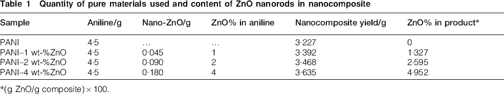
(g ZnO/g composite)×100.
Characterisation of PANI and PANI–ZnO nanocomposites
In order to characterise synthesis materials, the following methods were used:
X-ray diffraction analysis: the powder XRD patterns were recorded on a Brucker D8 Advance AXS diffractometer with Cu Kα radiation source (λ = 1·54 Å) operated at 40 kV and 40 mA in the 2θ range 10-80° at the scan range of 0·05° s−1
Fourier transform infrared spectroscopy (FTIR): FTIR spectra were recorded with a Bruker Tensor 27 spectrometer over the wave number range of 4000-400 cm−1. The spectra of ZnO nanorods, PANI and PANI–ZnO nanocomposites were taken as KBr discs
electron microscopy analysis: the transmission (TEM) and scanning (SEM) electron micrographs of PANI and nanocomposites were taken using SEM (MV2300 Cam Scan) and TEM (Ziess 100 KV). The pigment was spread over an aluminium block over which gold was sputtered in order to prepare for SEM studies
electrical conductivity measurement. The electrical conductivity of PANI and nanocomposites was found by homemade four-probe resistivity meter in room temperature.
Preparation of PANI and PANI–ZnO composite containing paint
In order to prepare paint coatings, a certain amount (0·306 g) of the synthesised powder of PANI or PANI–ZnO nanocomposite was suspended in 3 mL TEPA, followed by proper mixing using a magnetic stirrer, with a speed of 400 rev min−1 for ∼12 h. Tetraethylenepentamine acts as a hardener and solvent for epoxy resin. One gram of epoxy was mixed with 0·2 g suspension mixture, and the solution was stirred again (5 min). Epoxy resin acts as a binder for the nanocomposites in order to obtain a thick and uniform coating on steel. After stirring, a homogeneous composite was obtained. Steel plates were grinded, polished and coated with the developed paint. The liquid paints were coated on substrate by dipping and then dried in 50°C for 24 h. The dry film thickness of the coating was 150±10 μm. Since a coating thickness of 150 μm or more is generally employed for protection of marine structures, the coating thickness of 150±10 μm was achieved in this study. The composition of the prepared epoxy, epoxy/PANI and epoxy/PANI–ZnO paints is given in Table 2.
Synthesis condition of epoxy/PANI–ZnO coatings
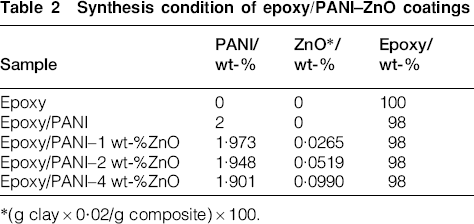
(g clay×0·02/g composite)×100.
Coating evaluation
Water uptake studies of coating
In order to investigate the water uptake properties of the coatings, the total paints system were applied over 4×6 cm glass plates by brush and allowed to cure for 4 days at 25°C. Then, these coated panels were weighed and immersed in 800 cm3 of distilled water. After removing the surface water by a filter paper, they were reweighed. This process was carried out up to 30 days. The accuracy of the weight measurement is ±0·1 mg.
Corrosion tests
Corrosion behaviour of epoxy coatings was investigated by electrochemical impedance spectroscopy (EIS) and variation of open circuit potential (OCP) using an impedance/potentiostat instrument (Zahner-model IM6). Experiments were made using a conventional three-electrode electrochemical cell. The working electrode was a carbon steel (St37) sample of 1 cm2 area coated with the pains. A rectangular platinum foil of 2 cm2 was used as counterelectrode, and a saturated calomel electrode was used as a reference electrode. These electrodes were placed inside the glass content of the solution of 3·5% NaCl. The EIS studies were carried out from 0 to 120 h (i.e. 0, 4, 22, 25, 28, 46, 70, 96 and 120 h) at the temperature of 65±2°C. In addition, impedance measurements were carried out at a frequency ranging 100 KHz to 0·01 Hz with an amplitude of 20 mV. Recorded Bode and phase plots of the impedance data were analysed with ZView software. Furthermore, OCP was measured for 40 days at the temperature of 25°C. It should be mentioned that all measurements have been carried out at OCP.
In order to evaluate the adhesion properties of the epoxy/PANI–ZnO nanocomposite, the coating was tested by ASTM D3359. 29
Results and discussion
Characterisation of pigments
X-ray diffraction patterns
In Fig. 1, a typical XRD pattern of synthesised ZnO nanorods was shown. The detected diffraction patterns can be easily matched with the standard database for Wurtzite hexagonal ZnO (JCPDS, card no. 36-1451) with lattice constants of 3·438 and 5·183 Å. Any further peaks were not observed in the XRD patterns, indicating that the purity of ZnO nanorods is high. Sharp nature of the distinguished peaks in the XRD pattern of ZnO nanorods implies high crystallinity or polycrystalline nature in the final product.28,30,31
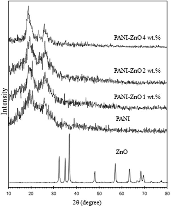
X-ray diffraction pattern of ZnO nanorods, PANI and PANI–ZnO nanocomposites
Figure 1 also shows typical XRD patterns of PANI and PANI–ZnO nanocomposites. The two main Bragg diffraction peaks of PANI appeared at angles of 2θ = 19·3° and 2θ = 25·7° in the spectrum. The presence of the rigid aromatic backbone of PANI makes PANI a semicrystalline polymer. 32 In addition, it can be seen that the XRD pattern of nanocomposites is similar to that of PANI. This is because of the presence of negligible content of ZnO nanorods, <5%, causing no diffraction. By adding ZnO nanorods, two distinct sharp peaks at 2θ = 19·3° and 2θ = 25·7° are shifted negligibly, but the intensity of them increases as the content of ZnO nanorods in PANI–ZnO nanocomposite increased.32,33
Infrared analysis
In Fig. 2, the FTIR patterns of ZnO nanorods, PANI and PANI–ZnO nanocomposites are shown. The characteristic absorption bands of PANI are 515·71 cm−1 (C—N—C bonding mode of aromatic ring), 592·85 and 700·84 cm−1 (C—C, C—H bonding mode of aromatic ring), 831·98 cm−1 (C—H out of plane bending in benzenoid ring), 1040·26 and 1155·97 cm−1 (S = O bonding for camphorsulphonic acid), 1302·53 and 1503·09 cm−1 (C—N stretching of benzenoid ring) and 1572·52 cm−1 (C = N stretching of quinoid ring). It was reported that the presence of the benzenoid and quinoid units is an evidence of the emeraldine structure of PANI. The PANI–ZnO nanocomposites show the same characteristic peaks. However, there is an evidence of peak displacement when ZnO nanorods are added to PANI. These shifts include 1572·51 to 1587·94 cm−1, 1503·09 to 1510·81 cm−1, 1155·97 to 1148·25 cm−1, 1040·26 to 1047·97 cm−1, 831·98 to 862·84 cm−1 and 592·85 to 600·23 cm−1. Additionally, in the case of PANI–ZnO nanocomposites, a broad peak appeared in 3270 cm−1.
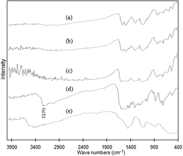
Fourier transform infrared pattern of ZnO nanorods, PANI and PANI–ZnO nanocomposites
It is clear that the corresponding peaks are shifted to the higher wave number, and their intensities are changed after the addition of ZnO nanorods. According to the patterns, absorption intensity is also increased by adding ZnO nanorods. The peak displacement observed in FTIR spectra may be attributed to the formation of hydrogen bonding between ZnO and the N–H group of PANI on the surface of the ZnO nanorods.34–37 Finally, these shifts of characteristic peaks and physicochemical interactions between ZnO nanoparticles and PANI molecules affect the electron densities and bond energies of the PANI. The shifting to the higher wave number can be attributed to the decreasing the electron density of the PANI chains, which can lead to reduction in the electrical conductivity of the nanocomposites. 38
Electron microscopy studies
Morphology of the synthesised nanocomposites was observed by electron microscopy. Images (SEM) of the PANI and PANI–2 wt-%ZnO nanocomposite are shown in Fig. 3. Agglomerated PANI can be seen in Fig. 3a, while PANI–2 wt-%ZnO nanocomposite has flaky shaped structure (Fig. 3b), in which PANI has covered ZnO nanorods. This nanocomposite seems to obtain an improved capacitance due to surface effects. As PANI has various structures, such as granular, nanofibre, nanotube, nanosphere microsphere and flake, 39 the SEM images reveal that the doping anions and ZnO nanorods have a strong effect on the morphology of PANI.
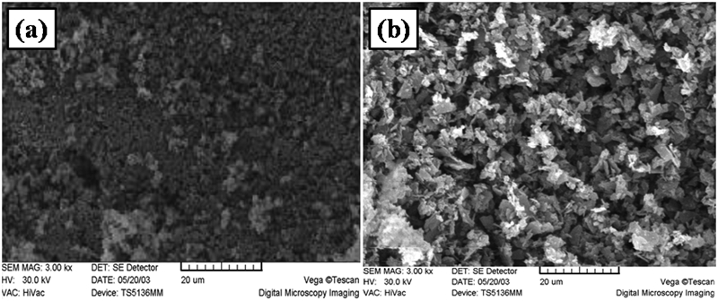
Scanning electron micrograph of a PANI and b PANI–2 wt-%ZnO nanocomposite
In Fig. 4a, TEM image micrograph of ZnO nanorods is shown. The TEM analysis of ZnO nanorods reveals that these nanoscaled materials have diameters ranging from 20 to 50 nm and lengths ranging from 50 to 200 nm. Additionally, the morphology of the PANI–2 wt-%ZnO nanocomposite was determined by TEM. According to the TEM images in Fig. 4b, PANI and ZnO nanorods have formed nanocomposite in which the ZnO nanorods were uniformly coated by PANI. This micrograph confirms that ZnO nanorods were covered by PANI uniformly.
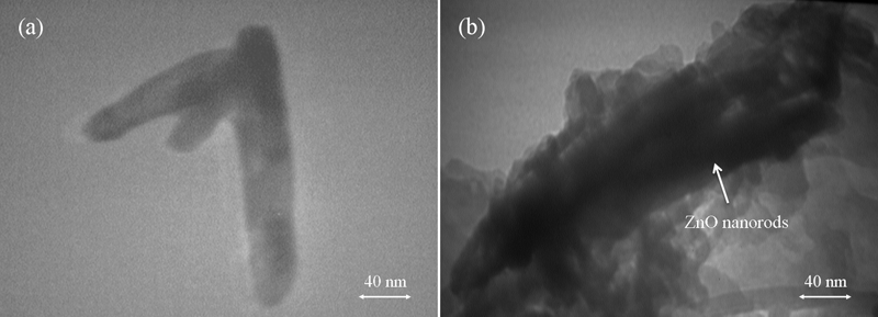
Images (TEM) of a ZnO nanorods and b PANI–2 wt-%ZnO nanocomposite
Conductivity studies
Figure 5 shows the result of electrical conductivity of ZnO nanorods, PANI and PANI–ZnO nanocomposites. Electrical conductivities in PANI and ZnO nanorods are 0·025 and 0·016 S cm−1 respectively, but in the case of PANI–1 wt-%ZnO nanocomposite, electrical conductivity is reduced and it is ∼0·0068 S cm−1. Rising the content of ZnO nanorods from 1 to 2 and 4 wt-% imposes an effect on electrical conductivity, and it was decreased from 0·0068 to 0·0029 and 0·0014 S cm−1. The decrease in conductivity of PANI–ZnO nanocomposites may be attributed to the behaviour of the ZnO in the nanocomposites 14 that by increasing amount of ZnO nanorods, the possibility of bond formation between –NH of PANI on the surface of ZnO nanorods is increased and the relative contents of the conducting polymer PANI in comparison to the amount of ZnO nanorods decreased. 40 Moreover, based on the FTIR obtained results taken from synthesised materials, it revealed that the reduction in electrical conductivity in the case of nanocomposites can be attributed to the physicochemical interactions between PANI molecules and ZnO nanoparticles, which have an effect on the electron densities and bond energies of the PANI. In other words, the shifting in the wave numbers to the higher ones can be associated to the declining in the electron density of the PANI chains, which leads to reduction in the electrical conductivity of the nanocomposites 38
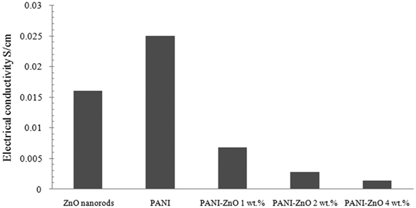
Electrical conductivity of ZnO, PANI and PANI–ZnO nanocomposites
Evaluation of coating
Water uptake studies
Water uptake value of coatings with immersion time was depicted in Fig. 6. It is observed that the epoxy coatings containing PANI–ZnO nanocomposite have lower water absorption than PANI containing or without additive. In the presence of nanocomposite, penetration of water in paint film is prevented.
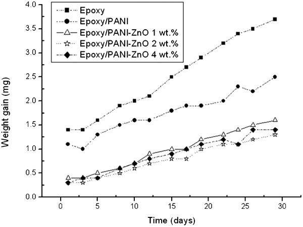
Water uptake variations of different paints film
As it was mentioned, ZnO nanorods can reduce water diffusion in the paint. As is clear, at the presence of ZnO nanorods, penetration and diffusion path of water molecules restricted in paint film and the performance of the coating against the water penetration was improved significantly.
According to the reports, 11 ZnO is an n type semiconductor and PANI is a p type semiconductor; thus, they may form a p–n junction, which will allow the ions to transport in only one direction in the coating system. Furthermore, ZnO nanorods have reinforcing effect in epoxy network structure due to rod-like structure, which can reduce penetration and water absorption in paint film; therefore, swelling and degradation of paint film will be reduced considerably.
Electrochemical studies of coated steel
In this part, different methods were used to evaluate corrosion protection performance of coatings, such as EIS and OCP. The corrosion protection performance of epoxy coating and epoxy/conductive polymer containing coatings on iron substrate was investigated in 3·5% NaCl solution as corrosive media for different immersion times up to 120 h at a temperature of 65°C.
Open circuit potential studies
Open circuit potential of the iron coated by epoxy, epoxy/PANI and epoxy/PANI–ZnO with different amounts of ZnO nanorods (epoxy containing pure PANI) from 0 to 4 wt-% were measured against time in 3·5% NaCl solution. Figure 7 shows the variation of OCP with time for the low carbon steel coated with epoxy alone and blended with PANI and PANI–ZnO nanocomposites in 3·5% NaCl solution. At first, the OCP values are shifted to active potentials for all coatings after up to 360 h. However, a subsequent exposure to the saline water changes the behaviour for the epoxy coating containing PANI and PANI–ZnO nanocomposites and OCP values return to noble direction. This can be due to ability of the PANI pigments in formation of the passive layer on metal substrate. Similar results for PANI containing coating were reported.3,4,18,41 As PANI is a conductive polymer, the electrochemistry during localised corrosion could occur differently.
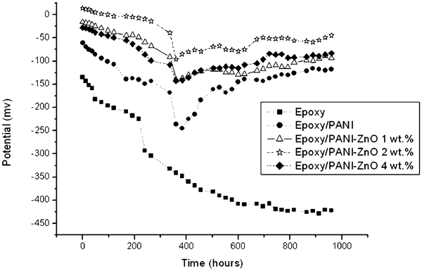
Open circuit potential variation of coated steel during 40 days immersion in 3·5% NaCl
Oxidation of iron to Fe2+ at the pinhole areas and defects causes the primary shift to active potential region, and PANI was converted from ES to leucoemeraldine base (LB) in the polymeric coating at the Fe/paint interface. By reduction in PANI-ES to LB, the sulphonate anions that are available as dopants in conductive polymer are released and become available at the interface of substrate and polymeric coating that they would tend to react with Fe cations and form a passivating complex.26,42 As a result of this reaction and formation of passive layer of iron complex, OCP will be shifted towards the noble direction in the case of epoxy/conductive polymer coatings. Additionally, the epoxy containing PANI–ZnO nanocomposites can be maintained in noble potential values in comparison to epoxy containing PANI due to uniform distribution of PANI in paint matrix and improvement of its performance at the presence of ZnO nanorods. In the presence of ZnO nanorods, Zn converts to Zn2+ acting as a cation ion. It was reported that even small percentages of these cations are able to inhibit the corrosion of substrate. Moreover, this inhibition phenomenon can be attributed to the blocking of the free iron surface for the cathodic complementary hydrogen evolution reaction and decreasing of the overall corrosion rate.11,42 In other words, Zn2+ cations interact with benzenoid or quinoid groups of PANI proved by the FTIR results of the synthesised material in this study. It was reported by Sathiyanarayanan et al. 3,42 that the metal cations interact with imine nitrogen atom of the PANI and change the morphology and structure of the PANI into compact cluster, which can profoundly reduce the corrosion rate. Finally, by addition of the metal oxide nanostructured materials, redox behaviour of PANI can be improved significantly. Based on other reports and our results, coating containing PANI and its nanocomposite with ZnO nanorods is able to achieve 100-400 mV potential in noble direction in 3·5% NaCl solution.3,11,25,41
Electrochemical impedance spectroscopy studies
Electrochemical impedance spectroscopy is a common method to evaluate corrosion protection performance of coatings. The EIS technique was used to determine the protective properties of the coating by measuring the resistance R c and capacitance C c of the paint coating using the equivalent circuit, as shown in Fig. 8. In the equivalent circuit, R s is the solution resistance, R c is the coating resistance and Q is the constant phase element of the coating capacitance. At the presence of defects in the coating, water and ions can transfer through the film and R c can be attributed to the electrical resistance owing to the ionic transfer through the coating pores. It normally decreases with time due to the penetration of electrolytes through the coating pores and defects.
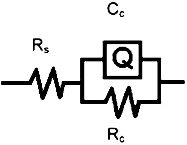
Equivalent circuit for painted steel panel
The impedance behaviour of epoxy paints and coatings containing PANI and PANI–ZnO nanocomposites was studied in 3·5% NaCl at 65°C. Figure 9a illustrates the Bode plot of epoxy coating, and the phase plot is shown in Fig. 11b. Moreover, Table 3 gives the corresponding impedance parameters derived from these curves. Initially, the resistance of the coating was 6·73×105 Ω cm2. After immersion for 120 h in saline hot water, the resistance of the coating decreased from 6·73×105 to 6·61×103 Ω cm2. It showed that the coating cannot act as a protective layer on the surface of the substrate at it gradually lost its performances.
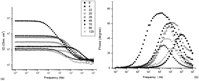
a Bode plots and b phase plots of epoxy paint coated steel in 3·5% NaCl at temperature of 65°C
Impedance parameters of epoxy paint coated steel in 3·5% NaCl at temperature of 65°C
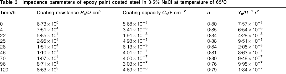
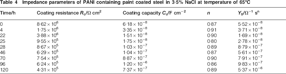
Figure 10 shows Bode and phase plots of the epoxy coating containing PANI. The variation of resistance and capacitance values of the epoxy/PANI coating against the immersion time is given in Table 4. In the beginning, resistance of the epoxy/PANI coating was 8·62×106 Ω cm2. It showed that PANI is able to improve performance of the coating in the corrosive environment. The resistance of the coating was found to decrease from 8·62×106 to 4·53×105 Ω cm2 after immersion for 120 h. Although the reduction in the coating resistance is less than that of epoxy coatings, epoxy containing PANI cannot be used in aggressive media due to its low resistance. The capacitance values of the epoxy/PANI coating remain approximately constant in the range 6·18×10−8–7·37×10−7 F cm−2.
a Bode plot and phase plot of epoxy/PANI paint coated steel in 3·5% NaCl at temperature of 65°C
Impedance parameters of PANI containing paint coated steel in 3·5% NaCl at temperature of 65°C
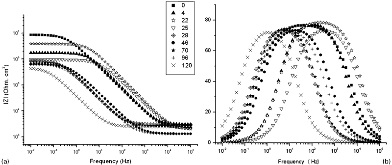
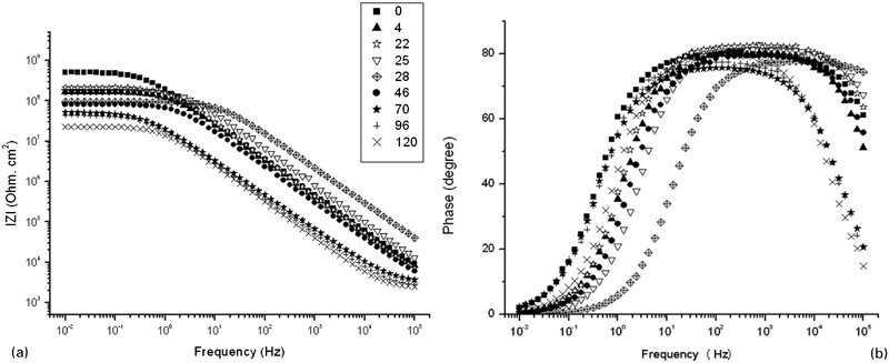
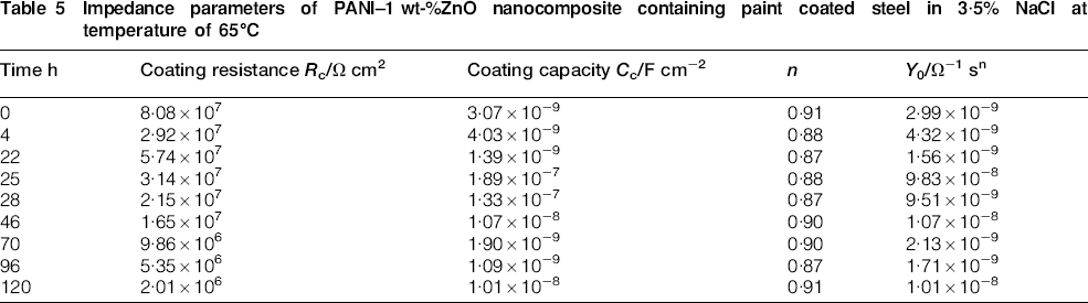
The variation of impedance of the coating containing PANI–ZnO nanocomposites with different ratios of ZnO nanorods is shown in Figs. 11–13. In Tables 5–7, impedance parameters for coatings of different composites versus period of immersion time are given. The resistance value of the coating containing PANI–1 wt-%ZnO (Fig. 11) was found to decrease from 8·08×107 to 2·92×107 Ω cm2 after 4 h immersion in hot saline media. Although with subsequent exposure for 22 h, the resistance value increased to 5·74×107 Ω cm2, it decreased slowly, and at the end of the 120 h exposure, the resistance value was 2·01×106 Ω cm2 and the capacitance values of the coating were in the range 3·07×10−9–1·01×10−8 F cm−2.
a Bode plot and b phase plot of epoxy/PANI–1 wt-%ZnO paint coated steel in 3·5% NaCl at temperature of 65°C
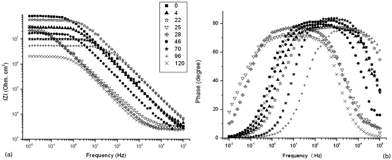
a Bode plot and b phase plot of epoxy/PANI–2 wt-%ZnO paint coated steel in 3·5% NaCl at temperature of 65°C
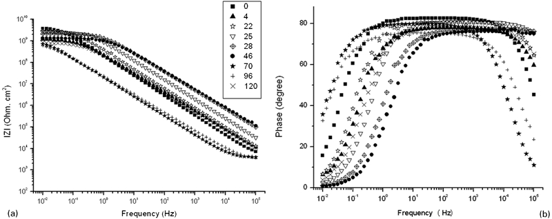
a Bode plot and b phase plot of epoxy/PANI–4 wt-%ZnO paint coated steel in 3·5% NaCl at temperature of 65°C
Impedance parameters of PANI–1 wt-%ZnO nanocomposite containing paint coated steel in 3·5% NaCl at temperature of 65°C
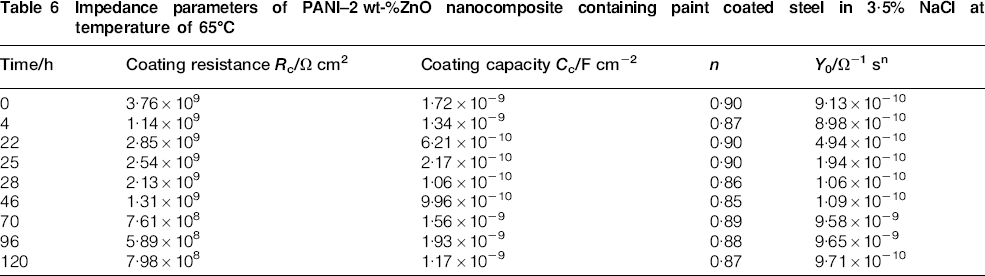
Impedance parameters of PANI–2 wt-%ZnO nanocomposite containing paint coated steel in 3·5% NaCl at temperature of 65°C
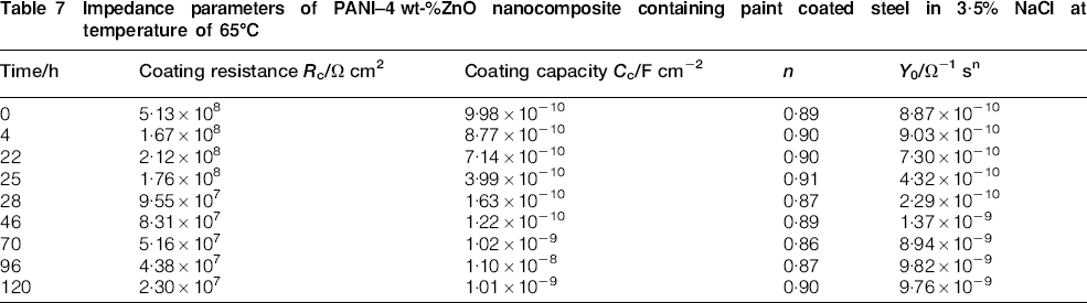
Impedance parameters of PANI–4 wt-%ZnO nanocomposite containing paint coated steel in 3·5% NaCl at temperature of 65°C
For a coating containing PANI–2 wt-%ZnO nanocomposite (Fig. 12a and b), initially, the coating resistance was 3·76×109 Ω cm2 and was reduced to 1·14×109 Ω cm2 with time. With more exposure in hot saline water for up to 22 h, the resistance of the coating increased to 2·85×109 Ω cm2. At the end of the 120 h immersion period in hot saline water, the resistance value of the epoxy/PANI–2 wt-%ZnO nanocomposite coating was 7·98×108 Ω cm2 and the capacitance values of the coating were in the range of 1·72×10−9–1·17×10−9 F cm−2, which indicated that no delamination has occurred during the period of study and that there was a low amount of water absorption into the paint film.
Finally, in the epoxy coating containing PANI–4 wt-%ZnO nanocomposite (Fig. 13), the resistance of the coating decreased from 5·13×108 to 2·30×107 Ω cm2 with time, although it increased from 1·67×108 to 2·12×108 Ω cm2 at 22 h immersion in hot saline water. Additionally, the capacitance values of the coating were in the range 9·98×10−10–1·01×10−9 F cm−2, indicating small changes.
Using the variation of coating capacitance against time, one can investigate water penetration into a coating. Figure 14 shows the variation of coating capacitance C c versus time for epoxy and epoxy containing conductive additives. Owing to nature of the epoxy coating, which is intuitively hydrophilic, water can be easily absorbed on the surface of the coating, so the possibility of penetration of water molecules into the paint film increases. As a result, the value of the coating capacitance changes. It can be seen in Fig. 14 that the epoxy coatings containing PANI–ZnO nanocomposite have the lowest variation, while in the case of epoxy and epoxy/PANI coating, variation is considerable, and after 120 h immersion in hot saline water, it increases significantly. Finally, in the presence of nanocomposite in the coating, corrosion protection efficiency of the epoxy can increase.
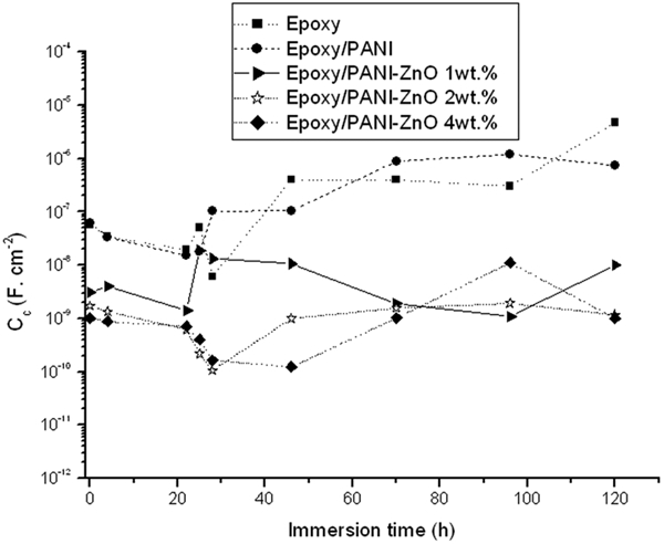
Variation of coating capacitance versus time
Variation of C c and R c with time could be explained by C c = ϵϵ 0A/d, where C c is coating capacitance, ϵ is the relative permittivity of coating, ϵ 0 is the permittivity of vacuum (8·85×10−14 F cm−1), d is the film thickness and A is the active area. Provided that water diffuses into the paint film, coating capacitance increases due to higher dielectric constant of water molecules in comparison to polymers. Therefore, variations in capacitance values are indicative of water uptake by the paint film, which causes changes in C c value. 19
In the case of epoxy containing PANI and PANI–ZnO nanocomposites, the coating resistance reduces initially, but after 22 h immersion in hot saline water, it increases. A subsequent immersion leads to reduction in coating resistance. Comparing the resistance values of the epoxy coating with those of the epoxy containing PANI and PANI–ZnO nanocomposite coatings, the PANI–2 wt-%ZnO nanocomposites have better performance about four orders in magnitude higher than epoxy and epoxy/PANI coatings respectively, which shows that the PANI–2 wt-%ZnO nanocomposite containing coating is more protective in the corrosive environment. In addition, the coating capacitance values for epoxy/PANI–2 wt-%ZnO nanocomposite remain in the range 1·19-1·73 nF cm−2 with immersion time. This shows that the amount of delamination occurring during the period of study is negligible and the amount of water absorption through the paint film is low. Since the degradation of the paint film depends on the coating resistance and capacitance value and an acceptable corrosion protection performance is achieved when coating resistance is >107 Ω cm2 and capacitance value is <10 nF cm−2,25 the results indicate that epoxy coating containing PANI–2 wt-%ZnO has the high corrosion protection ability in saline water.
Corrosion protection mechanism of iron at presence of PANI and ZnO nanorods
Polyaniline is a smart conductive polymer that helps in two different ways to prevent corrosion of steel:
it acts as a physical barrier in film paint
by formation of Fe2O3 on the surface of iron, it passivates the surface of metal substrate.
It has been reported that PANI can interact with many metal cations such as Ti4+ and Zn2+. These metal cations change the morphology of PANI into compact clusters on the metal/polymer interface and facilitate formation of passive layer.3,11,42 The protection mechanism of iron coated with epoxy containing PANI is propounded by Sathiyanarayanan et al. 2–4,18 as follows.
As is evident, the released anion dopants can form iron sulphonate complex compounds along with the passive film and underneath the coating.
In other words, PANI intercepts electrons at the metal surface and transports them to the outside of the primer. Therefore, it is expected that PANI captures the ions liberated during the corrosion reaction of steel in the presence of aggressive environment containing NaCl, water and oxygen and gets doped and liberates the dopant ions, which form a passive layer at the substrate/coating interface. Therefore, it acts as a self-healing coating with improved corrosion resistance.8,19
ZnO is an n type semiconductor, and when it is in contact with PANI, they may form a p–n junction, which will allow the electrons to transport in only one direction in coating system. Figure 15 shows the role of PANI–ZnO nanocomposite, which has an improved protection of steel in comparison of using PANI and ZnO nanorods alone in a coating system. According to the discussed theories, coatings containing PANI (Fig. 15, left) allow anions such as chloride and hydroxyl to transfer across the paint film during immersion in saline water. Therefore, these two anions accelerated the anodic dissolution of the metal 43 and stimulated corrosion of metal substrate. In the case of coating containing ZnO nanorods (Fig. 15, middle), paint films are permeable to cations, while anions are obstructed. After a short time, concentrations of Na+, Fe2+ and OH− were increased at the metal/polymer coating interface. Consequently, an iron oxide layer such as Fe2O3 or Fe3O4 will be formed on the metal substrate surface, and delamination will occur by increasing the concentration of the sodium hydroxide (NaOH). 43
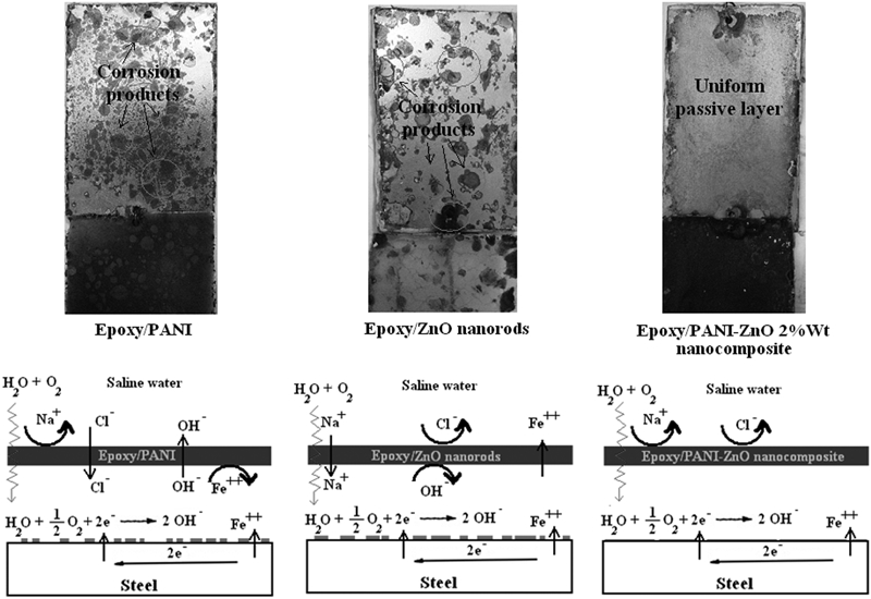
Passive layer formed at interface of substrate and paint film after immersion in 3·5% NaCl for 6 months
According to our results, coatings containing PANI lead to undercoating corrosion in saline environments and coatings containing ZnO nanorods lead to the delamination and degradation of coatings. To solve the above problems, the use of hybrid nanocomposite containing coating is the best solution because it offers a diode in paint film that limits ions transfer (Fig. 15, right).
Conclusions
Polyaniline and PANI–ZnO conducting nanocomposites have been prepared by the chemical oxidative method in the presence of aniline and ZnO nanorods by APS as an oxidant in CSA medium. XRD and FTIR studies have shown that the crystallinity of PANI is not affected in the PANI–ZnO nanocomposites and confirms the formation of nanocomposites. Studies on PANI and PANI–ZnO nanocomposite by SEM and TEM have shown that ZnO nanorods are uniformly covered by PANI. The corrosion resistance of the epoxy coating, epoxy containing PANI and PANI–ZnO nanocomposites was studied by the electrochemical methods. Coatings blended with PANI exhibit undercoating corrosion in saline environments and coatings blended with ZnO nanorods show delaminating and degradation of the coatings. Thus, the use of PANI and ZnO nanorods in the form of nanocomposite can not only solve these problems, but also increase the durability of the coating and corrosion protection of the substrate significantly. The EIS results under severe condition of hot saline media (at 65°C) show that the corrosion resistant property of the epoxy coating containing PANI–2 wt-%ZnO nanocomposite is found to be higher than coatings containing PANI–4 wt-%ZnO nanocomposite and PANI–1 wt-%ZnO nanocomposite due to the morphology of the PANI deposited on the ZnO nanorods and uniform coverage of ZnO nanorods by PANI polymer. Additionally, water uptake studies were reduced in epoxy/PANI–ZnO nanocomposites due to inhibition of penetrating water molecules. To conclude, epoxy/PANI–ZnO coating has better corrosion protection on steel substrates and the resistance value of epoxy/PANI–2 wt-%ZnO nanocomposite coating is nearly three orders higher than epoxy/PANI coating and four orders higher than epoxy coating, which shows that PANI–2 wt-%ZnO nanocomposite containing coating is more protective in corrosive environment and can protect surface of low carbon steel in saline media. Rod-like morphology of the zinc oxide nanostructure can play as a building block in paint film, which prevents or postpones penetration of water molecules in the coating system.
Footnotes
Acknowledgements
The authors would like to thank the Department of Materials Engineering in Sahand University of Technology. We would also like to acknowledge the support of the Iran Nanotechnology Initiative Council. Dr M. G. Hosseini is acknowledged for useful discussions.