
Abstract
The surface modification of commercially pure titanium (CP-Ti) by microarc oxidation (MAO) under different voltages was investigated using 1%H3PO4 solution as an electrolyte. The microstructure, phase composition and elemental distribution of ceramic coatings were investigated using scanning electron microscopy (SEM) and X-ray diffraction. The corrosion behaviour of the coating was also examined by potentiodynamic polarisation testing in a 3·5 wt-%NaCl solution. Micropore oxide films were formed on all the sample groups by MAO. The thickness and micropore size of the MAO coating increased with the increasing voltage. Energy dispersive X-ray spectroscopy results indicate that Ti, O and P became incorporated into the MAO coatings. At a low voltage of 250 V, the MAO coatings were composed of amorphous, P2O5, TiP2O7 and titania phases (rutile and anatase). Variation of treatment voltages increased the ceramic coatings from an amorphous structure to a phase structure, and the P2O5 phase disappeared. The corrosion potential Φcorr of the MAO sample shifted towards nobler directions, and the corrosion density I corr fell significantly compared with that of the bare CP-Ti. Corrosion testing showed that the sizes of the micropore of the MAO samples obviously decrease, and the MAO surface becomes smooth.
Introduction
Titanium and titanium alloys are used in many applications, from aerospace to biomedical sciences. They have excellent properties, such as high specific strength, good formability, corrosion resistance and excellent biocompatibility.1–3 Commercially pure titanium (CP-Ti) is an emerging titanium alloy and is widely used in the chemical, nuclear and, especially, biomedical industries. 4 However, poor corrosion and tribological properties greatly restrict the applications of such alloys, and therefore, they are usually used with protective coatings.5,6 In recent years, many surface treatment technologies have been studied for use with titanium and its alloys, most notably anodising, 7 physical vapour deposition, 8 nitriding, 9 sprayed 10 and ion implantation surface treatment. 11 Recently, microarc oxidation (MAO) has been developed to provide coatings for Al, Ti and Mg components,12–14 as these ceramic coatings have good wear resistance, high corrosion resistance and, especially, good adhesion between metal and coating in comparison with the conventional anodising treatment. The treatment of biomedical titanium and titanium alloys by MAO to improve their corrosion resistance and bioactivity has been widely investigated.15–18 Chen et al. 17 reported that microstructure characterisation of the oxidised TiO2 layer can be greatly affected by the discharge voltage and treatment time on Ti13Cr3Al1Fe β-titanium alloy during MAO treatment.
However, little has been published on the effects of discharge voltage on the characteristics and corrosion resistance of the ceramic coating, especially a coating on CP-Ti. In this study, MAO coatings were prepared in phosphoric electrolyte by applying different voltages. The morphology, microstructure, phase constituents and corrosion resistance of the MAO coatings were analysed. The corrosion behaviour was also evaluated by potentiodynamic polarisation in 3·5 wt-%NaCl solution.
Experimental
A CP-Ti having the nominal composition of 0·08 wt-%Fe, 0·02 wt-%N, 0·012 wt-%H, 0·10 wt-%O, <0·04 wt-%Si and the balance Ti was used as the substrate material for MAO coating deposition in the present study. The specimen was cut into squares 20·0×20·0×1·0 mm. After polishing and cleaning in acetone and distilled water, the specimens underwent MAO in an aqueous solution composed of electrolytes prepared with 1%H3PO4. During MAO treatment, the specimen was placed as the anode surrounded by a water cooled stainless steel tank as the cathode (Fig. 1). The electrolyte temperature was maintained within 20±2°C. The MAO coatings were produced at a constant current density of 33 A dm−2 for the same time period of 30 min by controlling the voltage. The applied DC voltage was varied from 250 to 350 V.
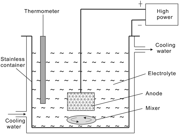
Device for MAO treatment
The morphology and composition of the MAO coating were examined by scanning electron microscopy (SEM; Hitachi S-4700, Japan) and energy dispersive X-ray spectroscopy (EDS; XFlash 4010 detector, Bruker, Germany). The crystal phase was analysed by X-ray diffractometry (XRD; Dmax 3-A type, Rigaku Co., Japan) using a step scan mode with a step size of 0·02° in the range of 20-80°.
Electrochemical polarisation experiments were performed using a typical three-electrode cell, no stirring and degassing of the solution at room temperature by an EG&G M273A potentiostat. The reference potential was a saturated calomel electrode (SCE) and Pt counter electrode (Φ 1·5 mm×20 cm). All electrolytes were prepared by dissolving high grade chemicals in high purity deionised water (18 MΩ cm; Millipore Milli-Q SP). The specimen surfaces, with an area of ∼2·829 cm2, were exposed to the 3·5 wt-%NaCl solution at 25°C. For dynamic polarisation testing, the potential began at −1·0 V(SCE) and scanned in the noble direction to an anodic 2 V(SCE) at a scanning rate of 1 mV s−1.
Results and discussion
Microstructures
Figure 2 shows the surface morphologies of the CP-Ti after MAO using different treatment conditions. Before the oxidation treatment, only the machining grooves were observed on the surface. When a pulsed dc field of 250 V was applied, a porous oxide layer began to be formed, as shown in Fig. 2a and b. As shown in Fig. 2a, the surface morphology of the CP-Ti was inhomogeneous after oxidisation at 250 V. It was composed of two distinct regions (regions a and b). In region a, oxides formed around the accumulated micropores. However, region b presented a much smoother surface. Small amounts of oxides formed in this region. Some microbulges in region b had regular and circular shapes with size of 0·1-0·2 μm in diameter. Han et al. 19 reported that the MAO film matrix appears to be very dense and is composed of 10-20 nm nanocrystallised grains. Figure 3 shows the relationship between the thickness and micropore size of the MAO coatings. It can be noted that both the thicknesses and the micropores of the MAO coatings increased with increased voltage. This indicates that the higher discharge voltage led to increased sparking discharge intensity by the pulse energy, which contributes to the enlarged thickness and micropore size. A similar result was also reported by Ref. 17.
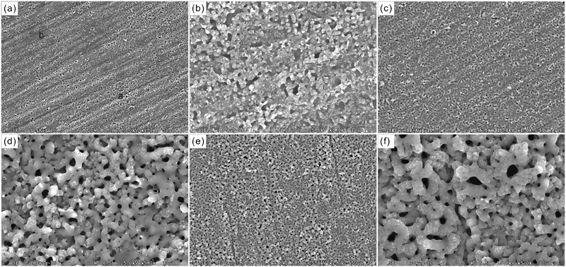
Surface morphologies of MAO samples formed at voltages of a 250 V (b higher magnification of a), c 300 V (d higher magnification of c) and e 350 V (f higher magnification of e)
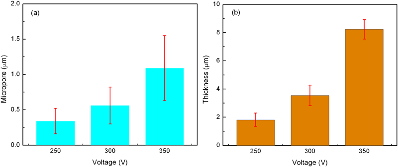
a sizes of micropores and b thickness of MAO coatings formed on CP-Ti at different voltages
Phase composition
Figure 4a shows a typical cross-section morphology of the MAO 300 V sample. It clearly shows that the coating was compact, with few defects (mark A), registering a regular thickness of ∼3·55±0·72 μm. Figure 4b and c displays the EDS analysis of the MAO coating surface and inner layer (Fig. 4a, mark B) on the CP-Ti respectively. Figure 5 and Table 1 show the results of EDS analysis for various MAO samples. The analysis revealed that the MAO 250 V sample mainly consisted of Ti and O, with weight concentrations of 49·92 and 47·29% respectively. Also in the surface layer was P, which came from solution anions. According to the EDS analysis, the concentrations of P and O increased with increasing MAO voltage, while that of Ti decreased steadily, as shown in Fig. 5 and Table 1. A similar result was also reported by Li et al. 20 However, P was not found in the inner MAO layer (mark B). This indicates a diffusion reaction at the Ti/TiO2 interface during the MAO process.
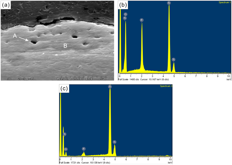
a typical cross-section morphology of MAO coated CP-Ti and b EDS analysis of surface of MAO coating and inner layer (mark B) on CP-Ti
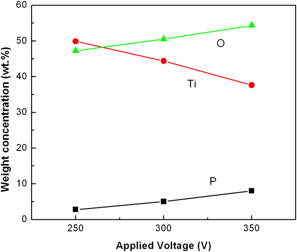
Chemical composition of surface layer as function of MAO voltage
Results of EDS analysis of zone indicated in Fig. 2
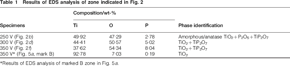
*Results of EDS analysis of marked B zone in Fig. 5a.
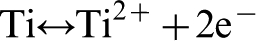
First, the TiO2 is coated during the MAO process by the following steps21,22
Oxide interface
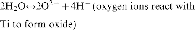
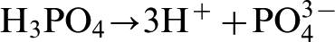
Thus, the major composition of the MAO coating is TiO2. As electrolytic anions are transmitted during anodisation, P and Ti percolate into the TiO2. Therefore, it is considered that TiO2 and  exist as Ti and P. As shown in Fig. 4b and c, the elements Ti, O and P are distributed in the MAO coating. During the anodising process, among the mixed electrolytes
 ion exists in the MAO TiO2 coating. It is predicted that P2O5 and P remain in the surface and do not ionise, where the oxide film is mixed with electrolyte solution. Park
23
evaluated that anodic titanium oxide film for biomedical applications was synthesised by anodic oxidation in acid solution (H2SO4 and H3PO4). During anodisation,
ion exists in the MAO TiO2 coating. It is predicted that P2O5 and P remain in the surface and do not ionise, where the oxide film is mixed with electrolyte solution. Park
23
evaluated that anodic titanium oxide film for biomedical applications was synthesised by anodic oxidation in acid solution (H2SO4 and H3PO4). During anodisation,  was separated into
  . When the
  ion was mixed in the process of film formation, the H+ ion disappeared. The incorporated phosphate species were found mostly in the forms of
  ,
,  and
and  . In addition, Ti, O and P were well dispersed in the TiO2 oxide film. In addition, Li et al.
20
studied the TiO2 films for photocatalyst prepared by anodisation in acid solution (mixing H2SO4, H3PO4 and H2O2). The components of the electrolyte, P and S, were found inside the photocatalyst layer as a form of P2O5,
. In addition, Ti, O and P were well dispersed in the TiO2 oxide film. In addition, Li et al.
20
studied the TiO2 films for photocatalyst prepared by anodisation in acid solution (mixing H2SO4, H3PO4 and H2O2). The components of the electrolyte, P and S, were found inside the photocatalyst layer as a form of P2O5,  , TiO2 (anatase and rutile) and Ti2O3, which were incorporated from the electrolyte into the oxide layer during anodisation. In general, at the sparking areas, a localised high temperature can be produced. The temperature at the sparking location has been evaluated at >1000°C,
24
and the temperature can be much higher in the centre of a sparking flame.
25
, TiO2 (anatase and rutile) and Ti2O3, which were incorporated from the electrolyte into the oxide layer during anodisation. In general, at the sparking areas, a localised high temperature can be produced. The temperature at the sparking location has been evaluated at >1000°C,
24
and the temperature can be much higher in the centre of a sparking flame.
25
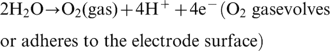
Finally, possibly due to the intensive local high temperature adjacent to the coating/electrolyte interface, which results in the evaporation of water in the reaction zone, TiP2O7 compounds were deposited on the sample surface, and the anatase TiO2 transferred to rutile TiO2, which possibly led to the occurrence of the following reactions


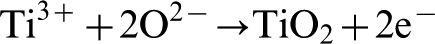
Based on the above analysis, the growth of the coating is closely associated with the sparks during the MAO process; much heat is generated locally as a result, and dissolution occurs at the same time. Such heat causes the Ti ions inside the disc to move to the surface and the OH− in the electrolyte and  ions generated from the positive pole to move into the internal disc. TiO2 is generated through the reaction of Ti ions and O ions. In this way, the oxidised film formed on the surface of the CP-Ti.
Figure 6 shows XRD patterns of MAO coatings formed on CP-Ti at different voltages. In the MAO 250 V sample, the coating was mainly composed of anatase TiO2 rutile TiO2, P2O5, TiP2O5 and a small amount of amorphous phase. Owing to the thinness and porosity, diffraction peaks of α-Ti substrate were reflected obviously in the XRD pattern. With increasing voltage, the intensity of α-Ti peaks, P2O5 and amorphous microstructure disappeared, while that of other peaks increased steadily. The XRD pattern for the MAO coating was composed of a large amount of anatase TiO2, rutile TiO2 and titanium pyrophosphate (TiP2O7), which was compatible with the MAO characteristics. It is reported that anodised nanotube layers can be transformed from an amorphous form into a mixture of anatase and rutile after annealing at temperatures >450°C, 26 which means that the MAO process can achieve suitable crystalline structures according to the application. Habazaki et al. reported that anodising of Ti involves an amorphous to crystalline transition in the oxide structure at relatively low voltages. 27 This agrees well with the results revealed by Li et al., 20 who used pure titanium to carry out MAO treatment.
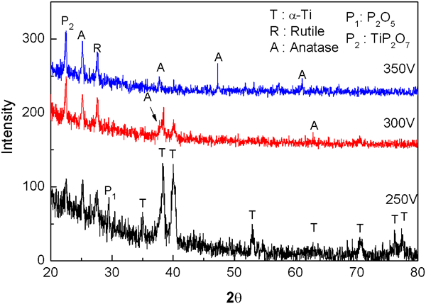
Patterns (XRD) of a CP-Ti substrate and MAO treated at voltages of b 250, c 300 and d 350 V
Corrosion behaviour
The potentiodynamic polarisation curves of untreated and MAO samples in 3·5 wt-%NaCl solution are shown in Fig. 7. The corrosion potential Φcorr, corrosion current density I corr and critical current density I crit of the uncoated and MAO samples are compiled in Table 2. The uncoated CP-Ti substrate had a low corrosion potential [−541·2 mV(SCE)] and high corrosion current density (2·80 μA cm−2), and its critical current density I crit was rather high, up to 37·0 μA cm−2. The corrosion current densities were obtained using the TAFEL extrapolation method. It can be seen that all the MAO samples exhibited a marked shift in Φcorr towards the noble direction, and a significant one-order decrease in the corrosion current density I corr and critical current density I crit as compared with the uncoated CP-Ti. The improvement in corrosion property observed for MAO samples is believed to be due to the coverage of the surface of the sample by the oxide ceramic coating, which serves as a barrier layer, physically separating the substrate and the corrosive medium. In addition, for MAO samples, the corrosion resistance increased from −260·1 to −168·2 mV(SCE) with increased voltage. That resulted from the effect of film thickness, especially the increase in the compact MAO layer when the total film thickness increased. The compact MAO layer of film played an important role in the corrosion protection of the CP-Ti. On the other hand, it was found that the corrosion current density increased slightly, from 1·42×10−7 to 3·55×10−7 A cm−2. Trepanier et al. 28 reported that the quality of the coatings in terms of evenness and compactness, not the thickness, is the most important factor determining the corrosion resistance of the samples. Vangolu et al. reported that the most effective parameter on the corrosion current density is the voltage, 29 due to the surface roughness of the MAO coatings increasing with increasing voltage. Thus, the corrosion current density increased slightly. Therefore, the micropores of the MAO coatings had a detrimental effect on the corrosion performance. Larger pores increased the real exposed area to the corrosive solution and may have concentrated the corrosion medium more than little ones did. 30
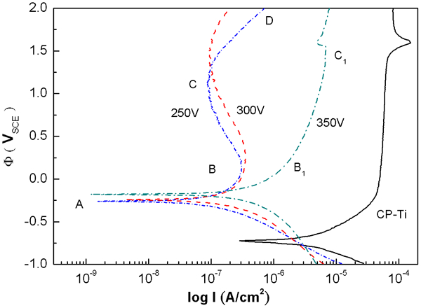
Polarisation curves of CP-Ti substrate and MAO coatings formed at different voltages
Results of potentiodynamic corrosion tests in 3·5 wt-%NaCl solution*
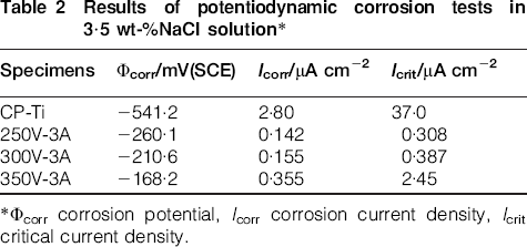
*Φcorr corrosion potential, I corr corrosion current density, I crit critical current density.
It is interesting that the anodic polarisation part consisted of several regions, namely, AB and CD. This feature could be attributed to several reactions on the electrode: TiO2 decomposition on the outer layer of MAO and the diffusion of ions through the interface between substrate and inner MAO film layer. Main reactions were thought to include

At point A, with increasing potential in the anodic direction, the outer layer of the MAO-TiO2 layer dissolution occurred according to equation (1). The active dissolution of TiO2 continued with increasing potential until the Ti(OH)4 concentration reached a critical value and supersaturated the surface of the MAO samples (point B). The anodic current density (point B) for the MAO sample at 250 V was found to be the maximum and to decrease with increases in potential up to C. This feature could be attributed to the reaction equation (9). However, the anodic current density of 350 V in the region (B1C1) slightly increased with increases in potential. This suggests that the thickness of the MAO coating layer increasingly suppressed the diffusion of ions through the interface between the substrate and the inner MAO film layer (equation 9).
Figure 8 shows the typical morphology of the coated samples after a polarisation test. As a result, both the micropore decreased and the flat-like structure (mark c) was observed. Furthermore, the micropore density of all MAO samples decreased. Therefore, the micropore density of all MAO samples decreased. In addition, the smaller prominent particles on a ridge (Fig. 2) disappeared after the dynamic polarisation test, as shown in Fig. 8.
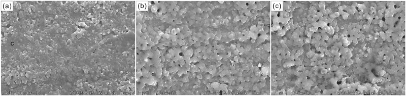
Surface morphologies of substrate and MAO coatings formed at different voltages after corrosion testing
It is considered likely that dynamic polarisation processes occurred, leading to surface dissolution and the formation of corrosion products around the micropores, with accompanying partial obliteration of the micropores. Shi et al. 25 reported that locally dissolved areas with irregular rough surfaces were observed on MAO Ti6Al7Nb alloy after the corrosion test, and this phenomenon was attributed to the dissolution of vanadium oxide in the film, which can explain the low corrosion resistance of the MAO Ti6Al4V alloy.
Conclusions
The effects of anodic oxidation treatment of CP-Ti on the microstructure and corrosion characteristics were investigated.
With increasing MAO voltage, the thickness and micropore size of the oxide layer increase, as do the concentrations of O and P in the oxide layer.
A low voltage of 250 V produces the MAO coatings composed of TiP2O7, titania phases (rutile and anatase), P2O5, and amorphous phase. Variation of treatment voltage increase leads to an obvious change of the ceramic coating from an amorphous structure to a phase structure, and the P2O5 phase disappears.
Compared to the CP–Ti sample, the corrosion potential Φcorr of MAO coatings moves to a more positive potential, and the corrosion current density I corr falls by one order of magnitude.
The corrosion resistance of MAO samples increases with increasing voltage, which is accompanied by a slight increase in the corrosion current density.
Corrosion testing showed that the sizes of the micropore of the MAO samples obviously decrease and the MAO surface becomes smooth.
Footnotes
Acknowledgements
The authors acknowledge the financial support of this work from the National Science Council of Taiwan under project nos. NSC 101-2622-E-020-006-CC3 and NSC 101-2221-E-020-011. The authors also thank S. F. Ping for the useful discussion and sample preparation. Scanning electron microscopy was performed by the Precision Instrument Center of National Pingtung University of Science and Technology, Taiwan.