
Abstract
In this study, corrosion behaviour of magnesium AZ31 alloy sheets produced by different casting methods was investigated. Magnesium AZ31 sheets of 2 mm in thickness produced by conventional direct chill casting+rolling and AZ31 sheets of 2 mm in thickness and 1500 mm in width produced by twin roll strip casting+rolling were used as samples. For the determination of processing method dependent corrosion behaviour, potentiodynamic electrochemical corrosion and also immersion tests were performed in 0.5M Na2SO4 and 0.01M NaCl solutions. Corrosion damage occurred during the tests was extensively investigated by scanning electron microscopy. Results of the work revealed the clear role of processing method dependent size and distribution of intermetallics on the corrosion behaviour of AZ31 sheets.
Keywords
Introduction
In recent years, there is an increasing interest in using lighter materials for various applications in transportation industry. Entering into action of Kyoto Protocol further motivated these activities. Magnesium, which is the lightest structural metal with a density of 1.74 g cm−3, is a potential material for the future transportation applications.1–3 Although magnesium components with their low density, high specific strength, good castability and machinability are very good candidates as structural materials, their low corrosion resistance is still a problem.4–9 Most corrosion studies about magnesium alloys in literature pertain to the effect of Cl− anions in the corrosion process of magnesium.5,10–18 There are few studies in literature on the corrosion behaviour and mechanism of magnesium alloys in neutral chloride free solutions.10,19–24
Song et al. 10 have shown that partially protective surface film played an important role in the dissolution of magnesium in chloride and sulphate solutions. Yang et al. 22 investigated the corrosion behaviour of die cast AZ91D alloy in NaCl, Na2SO4 and MgSO4 solutions. They reported that the corrosion rates in the sulphate solutions were lower than the corrosion rates in NaCl solution. In chloride containing solutions, corrosion of magnesium starts as pitting which covers the whole surface after an immersion time of 48 h. However, homogenous corrosion is the form of corrosion observed for the samples immersed in Na2SO4 and MgSO4 solutions. 22 Studies concerning the effects of grain size on the corrosion behaviour of magnesium alloys are present in the literature. 17
The definitive roles of intermetallics and alloying elements on the corrosion behaviour of magnesium alloys are very well known.7,13,25–30 Corrosion resistance of magnesium is improved with alloying them with more noble metals such as aluminum and zinc as long as their concentrations are within the solubility limits. The secondary phases formed by exceeding the limits of solubility and intermetallics are detrimental for the corrosion resistance of magnesium because of their high tendency for the initiation of microgalvanic regions. Almost all intermetallics formed in magnesium are cathodic to the matrix. Thus the distribution, size and the composition of these phases are expected to exert a prominent role on the corrosion and efficiency of corrosion protection methods of magnesium alloys.7,13,25–30
At present, magnesium automobile parts are commonly manufactured by using cast magnesium alloys since parts with complex geometry can be produced by die casting method. However, recently, interest in wrought magnesium alloys increased due to their better mechanical properties compared to cast alloys.31–34
In recent years, studies about the production of magnesium alloy sheet by twin roll strip casting technique (TRC) have been increased mainly due to economic reasons. In conventional magnesium alloy sheet production, many rolling passes and annealing processes at elevated temperatures are required in order to achieve thin sheets with optimal microstructure. Therefore, twin roll continuous casting technique, in which casting and hot rolling processes are combined into a single process, is considered as a more economical alternative technique to conventional magnesium alloy sheet production.35–40 The microstructure of the alloys produced by the above stated two techniques shows important differences with respect to the distribution and size of the intermetallics mainly due to the differences in solidification rate and the thermal processes.7,25,28
This work aims to investigate and interpret the corrosion behaviour of magnesium AZ31 alloy sheets produced by different casting methods, mainly concentrating on their differences in the microstructure. For this purpose, after a detailed investigation of the microstructure of the alloys, electrochemical corrosion tests and immersion tests were performed in NaCl and Na2SO4 solutions in order to provide further details regarding the corrosion behaviour and mechanism of AZ31 sheets.
Experimental
Material and microstructural characterisation
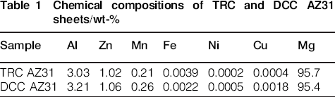
In the experimental studies, magnesium AZ31 alloy sheets of 2 mm thick produced by conventional direct chill casting (DCC)+rolling and AZ31 sheets of 2 mm in thickness and 1500 mm in width produced by TRC+rolling within the scope of a project of TUBITAK MRC Materials Institute supported by State Planing Organization of Turkey were used. Chemical compositions of the magnesium TRC and DCC AZ31 sheets were determined by Spectrolab M8 optical emission spectrometer (Table 1).
Chemical compositions of TRC and DCC AZ31 sheets/wt-%
Before the corrosion tests, microstructural properties of magnesium AZ31 sheets were investigated by optical metallography, scanning electron microscopy (SEM) and energy dispersive X-ray spectroscopy analysis to reveal the microstructural differences between them. Specimens were prepared by standard metallographic procedures in order to examine the microstructures in cross-section and plane views. The polished surfaces of AZ31 samples were etched using acetic picral acid solution (4.2 g picric acid, 10 mL acetic acid, 70 mL ethanol, 10 mL distilled water).
Electrochemical corrosion tests
Electrochemical corrosion tests were performed in 0.5M Na2SO4 and 0.01M NaCl solutions. Three electrode corrosion cells were employed in the experiments where AZ31 sheets, saturated calomel electrode and platinum were used as the working electrodes, the reference electrode and the counter electrode, respectively. The sheet samples were embedded in epoxy resin by leaving a surface area of 4 cm2 ready to be exposed to the electrolyte. Before corrosion tests, specimens were wet ground to P4000 grit SiC abrasive paper, followed by rinsing with ethanol and drying in warm air. Three identically prepared samples were used for each set of experiments conducted in both solutions.
For determining the polarisation behaviour of the alloys in Na2SO4 and NaCl solutions, a computer controlled potentiostat (Princeton Applied Research 263A) is used.
The open circuit potential (E OCP) measurements were recorded before polarisation in Na2SO4 and NaCl electrolytes for 2 h. Corrosion currents in Na2SO4 solution were determined from the polarisation curves by the Tafel extrapolation method. After stabilisation of the open circuit potentials of AZ31 sheets in 0.5M Na2SO4, polarisation curve measurements were carried out at a scan rate of 1 mV s−1, from −265 to +135 mV with respect to E OCP.
Cyclic polarisation measurements of AZ31 sheets in 0.01M NaCl were also performed at a scan rate of 1 mV s−1. The forward scanned polarisation curves started from a cathodic potential of −250 mV with respect to E OCP. After reaching an anodic current magnitude of 6×10⁻⁴ A cm−2 scan direction is reversed for obtaining the repassivation behaviour of the alloy.
After the corrosion tests, some of the specimens were immersed in a mixture of chromic acid and silver nitrate solutions (200 g L−1 CrO3+10 g L−1 AgNO3) for 5 min in order to remove the corrosion products and then the surfaces of the specimens were investigated with a scanning electron microscope (JEOL-JSM-6335F FEG-SEM) coupled with an energy dispersive spectrometer (Oxford Instruments).
Immersion corrosion tests
The immersion tests were carried out at room temperature in accordance to the procedure given in ASTM G31. Before the tests, specimens (∼2×2×2 cm) were wet ground to P4000 grit SiC abrasive paper followed by rinsing with ethanol and drying in warm air and then weighed.
After the corrosion tests performed in 0.5M Na2SO4 and 0.01M NaCl solutions for different time periods (2, 5, 8, 24, 48, 120 and 216 h), the specimens were immersed in a mixture of chromic acid and silver nitrate (200 g L−1 CrO3+10 g L−1 AgNO3) solutions for 5 min in order to remove the corrosion products. After removal of corrosion products, the TRC and DCC AZ31 sheets were washed with distilled water, dried and finally weighed. The immersion tests were repeated two times in order to obtain accurate weight loss results for each set of experiments conducted in both solutions. The corrosion current densities of the specimens are calculated by using Faraday equation.
After the immersion tests, the surfaces of the specimens were investigated with a scanning electron microscope (JEOL JSM-6510LV SEM) coupled with an energy dispersive spectrometer (Oxford Instruments).
Results and discussion
Microstructural characterisation
In the cross-sectional and plan view microstructures of TRC AZ31 and DCC AZ31, the most distinct difference is the presence of very high amount of twins and deformation bands in DCC AZ31 revealing the higher amount of deformation due to the processing difference (Fig. 1a–d). Secondary particles seen as black spots are observed in the cross-sectional and plan view images of DCC AZ31 and TRC AZ31 respectively (Fig. 1b and c)
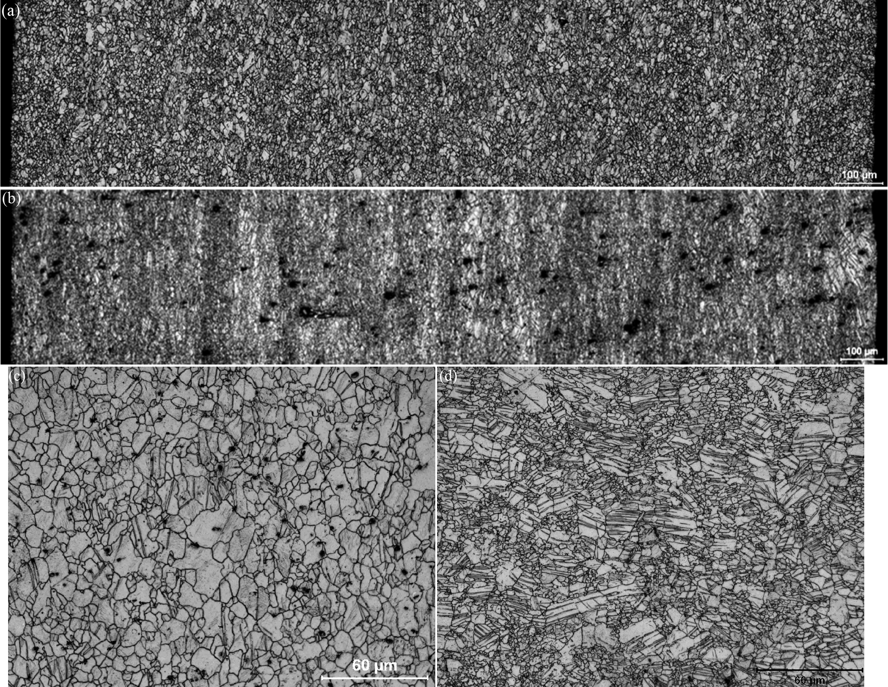
Optical micrographs showing cross-sectional and plane microstructures of a, c TRC and b, d DCC AZ31 sheets
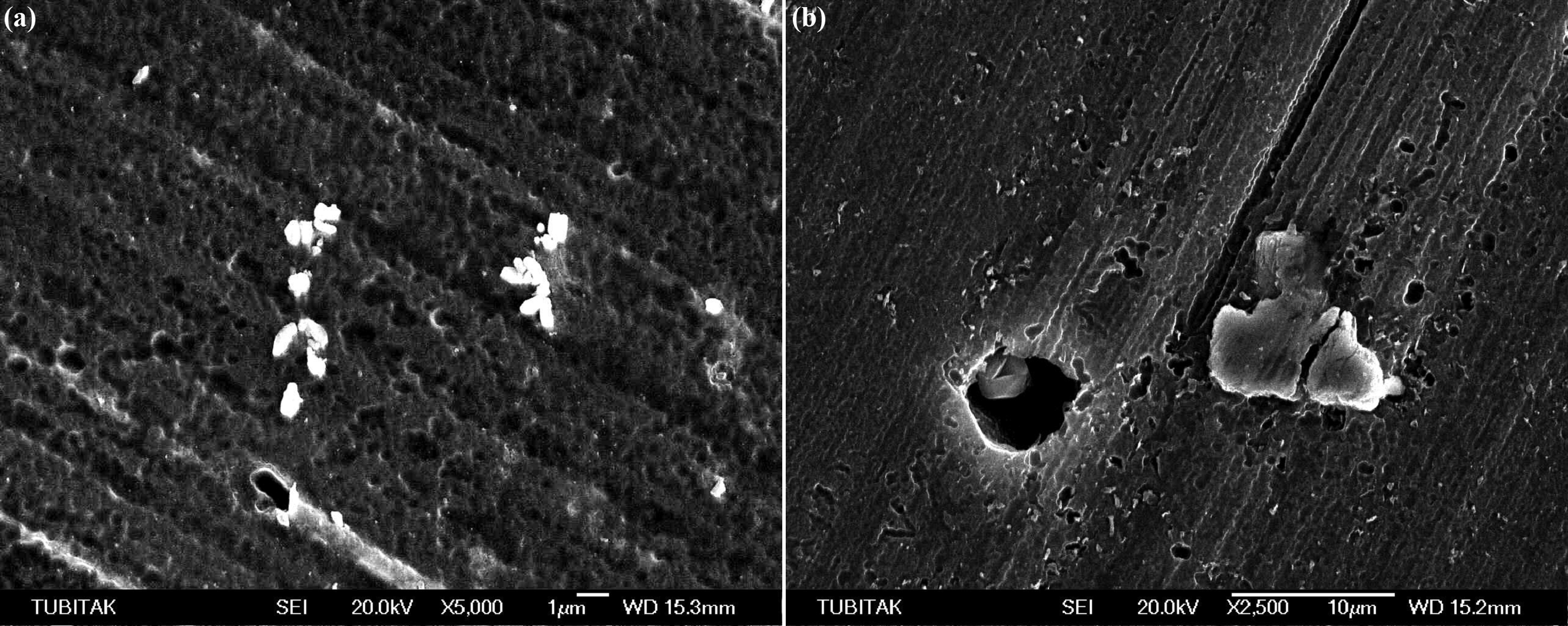
Scanning electron microscopy investigations are carried out in order to determine the composition and distribution of intermetallics. Energy dispersive X-ray spectroscopy analysis revealed that the intermetallics in both type of samples are Al–Mn based as expected. Some Al–Mn intermetallic phases containing iron were also detected both in TRC and DCC AZ31 sheets. Figure 2 shows the SEM micrographs of Al–Mn intermetallic phases in TRC and DCC AZ31 sheets. Characterisation studies indicated that the number of Al–Mn intermetallics present in TRC AZ31 sheet was higher with sizes smaller than these in DCC AZ31 sheet due to higher solidification rate (Fig. 2). The sizes of these homogeneously distributed intermetallics are in the order of submicrons in TRC AZ31 and they generally precipitated as clusters. In DCC AZ31 sheets the sizes of intermetallics are in the tenths of micrometre range and showed a random scattered distribution.41–43 A statistical study is conducted on 1000× SEM micrographs of DCC and TRC AZ31 sheets for the determination of the number of intermetallics per mm2. The numbers of intermetallics are in the range of 19 000±200 and 3800±50 mm−2 in DCC and TRC AZ31 respectively.
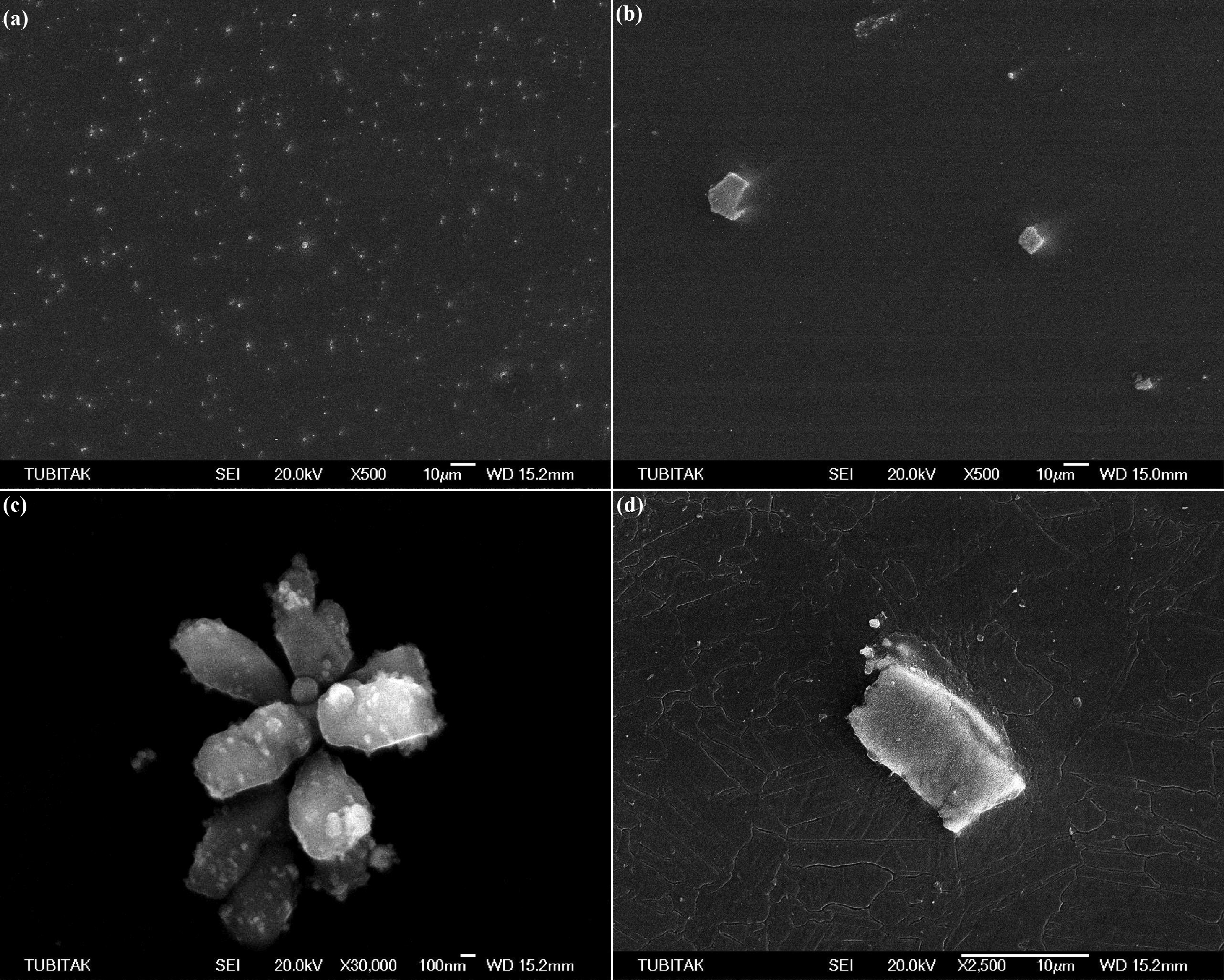
Images (SEM) of Al–Mn intermetallics in a, c TRC and b, d DCC AZ31 sheets
Electrochemical corrosion test results
Figure 3 shows the polarisation curves of TRC and DCC AZ31 sheets obtained in 0.5M Na2SO4 solution. Polarisation curves obtained in 0.5M Na2SO4 indicated that corrosion rates (i corr) of DCC AZ31 sheet were higher than that of TRC AZ31 specimen. However, there was no significant difference between the corrosion potentials (E corr) of the sheets. Table 2 presents E corr, i corr and βc values of TRC and DCC AZ31 sheets obtained from the polarisation curves acquired in 0.5M Na2SO4 solution. Upon further anodic polarisation of the samples, a passive-like behaviour was observed revealing the formation of a protective film on sample surfaces. In other studies conducted on AZ31 alloys in sodium sulphate solutions, similar cathodic and anodic behaviours were observed.20,21
Polarisation curves of a TRC and b DCC AZ31 sheets in 0.5M Na2SO4 solution. Solid lines indicate regions used for calculation of Tafel slopes
Corrosion parameters determined from polarisation curves for TRC and DCC AZ31 sheets in 0.5M Na2SO4 solution
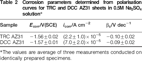
*The values are average of three measurements conducted on identically prepared specimens.
For the investigation of the anodic polarisation behaviour of TRC and DCC AZ31 sheets in chloride containing environments a dilute solution, 0.01M is selected. It is well known from the literature that in high chloride containing solutions (such as 0.5N) it is not possible to form a protective layer on magnesium and magnesium alloys. In these cases corrosion potentials overlaps the potential at which localised corrosion (pitting) initiates. Since we wanted to compare the role of different casting practices on the localised corrosion of AZ31 magnesium alloy a solution that will allow the formation of a protective layer before anodic polarisation was selected. In the previous studies 15 conducted on localised corrosion of Mg alloys it was clearly shown that it was possible to from a partially protective layer on magnesium alloys by keeping them for a period of 2 h at corrosion potential before anodic polarisation.
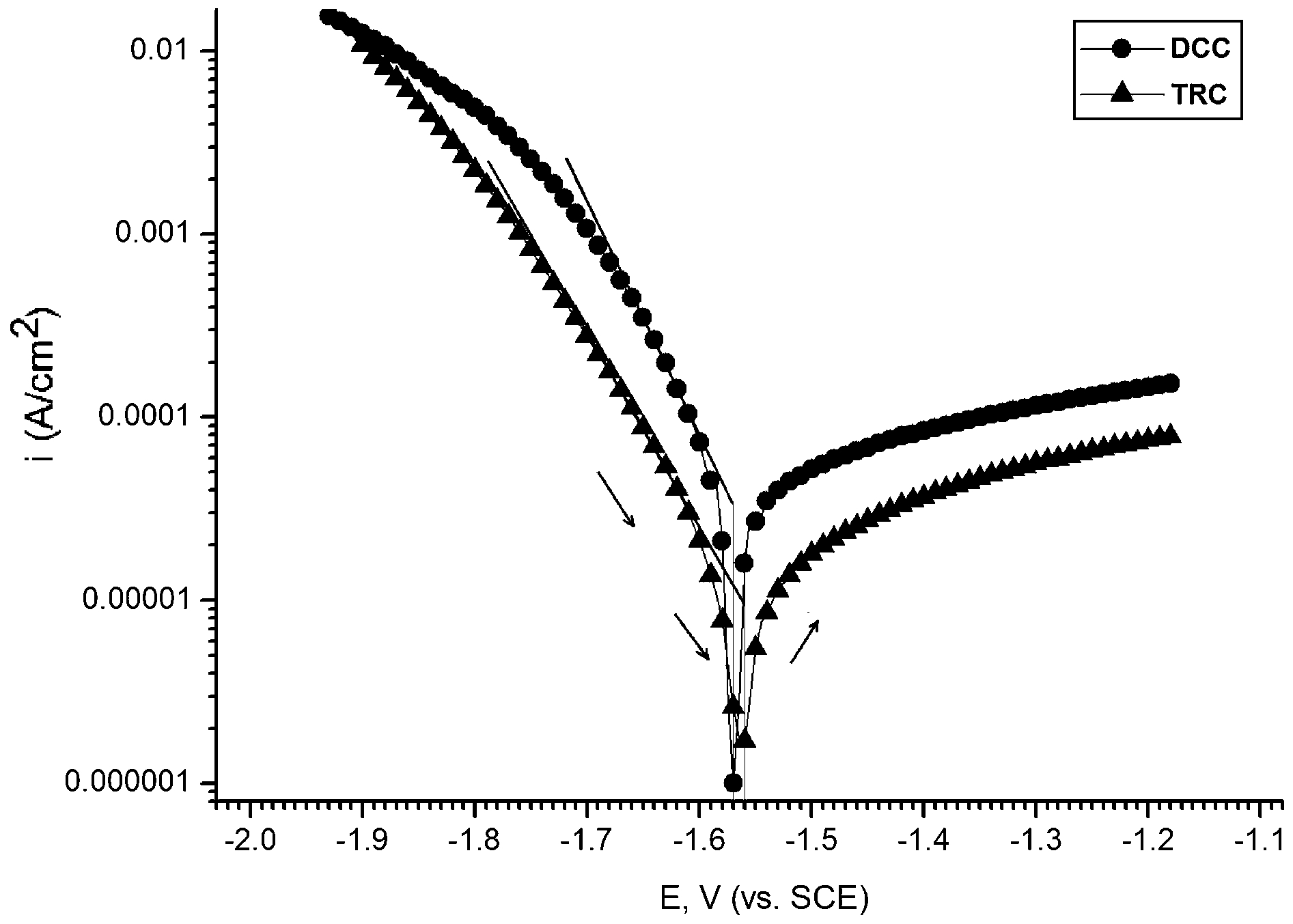
The polarisation curves of DC and TRC AZ31 alloys obtained in 0.01M NaCl solution are presented in Fig. 4. Starting from corrosion potential, after a gradual continuous rise in the anodic current, a relatively steep rise in the current started to be observed for both samples after reaching a current density of 0.2 mA cm−2. Thus on the forward polarisation curves, the potentials that corresponds to 0.2 mA cm−2 are selected as localised corrosion potentials (Table 3). Upon reversing potential application direction after reaching a current density of 0.6 mA cm−2 current did not decrease immediately it continued to increase and after reaching −1.25 V it started to decrease. The current during the reverse cycle was higher indicating the continuing corrosion activity on localised corrosion centres. The potential at which repassivation commenced was more negative than the initial corrosion potentials. The anodic polarisation curves of DC and TRC AZ31 are similar to each other. The localised corrosion (pitting) potentials at 0.2 mA cm−2 are very close. The major difference between the two samples polarisation behaviour is the higher magnitude of current after potential reversal and more negative repassivation potential of TRC AZ31 sample. This behaviour can be attributed to ongoing higher activity within the localised corrosion regions in TRC AZ31 sample before repassivation.
Polarisation curves of a TRC and b DCC AZ31 sheets in 0.01M NaCl solution
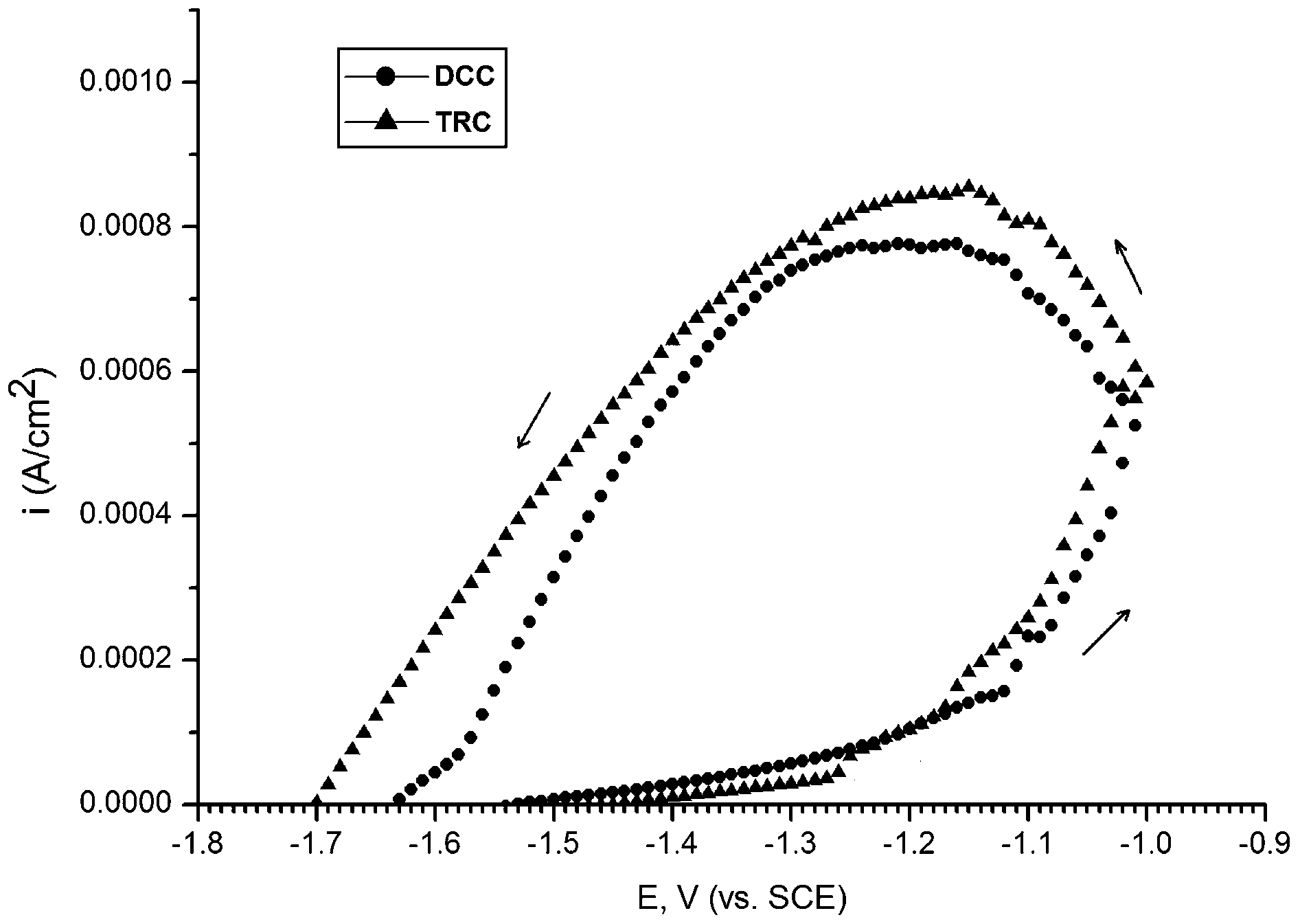
Corrosion parameters determined from polarisation curves for TRC and DCC AZ31 sheets in 0.01 M NaCl solution
*The values are average of three measurements conducted on identically prepared specimens.
Corrosion morphology of AZ31 sheets after polarisation tests in 0.5M Na2SO4 and 0.01M NaCl
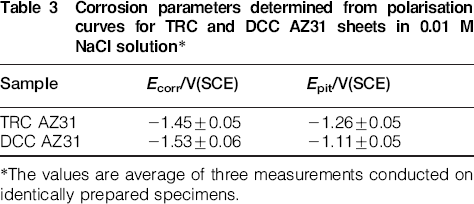
In the planar view of the corroded surfaces of TRC and DCC AZ31 sheets after the electrochemical tests in 0.5M Na2SO4 solution, the presence of Al–Mn intermetallic particles is clearly observable on both samples (Fig. 5c–f) (For comparison, the microstructures of samples that are not subjected to corrosion tests are presented in Fig. 5a and b). The peripheries of these intermetallics corroded preferentially indicating the formation of microgalvanic couples between Mg matrix and the intermetallics. In TRC sample, high amounts of microholes resulting from the falling away of small intermetallics during corrosion testing are also observable (Fig. 5e).
Images (SEM) of a as received TRC; b as received DCC; c, e TRC and d, f DCC AZ31 sheets after electrochemical corrosion tests in 0.5M Na2SO4 solution
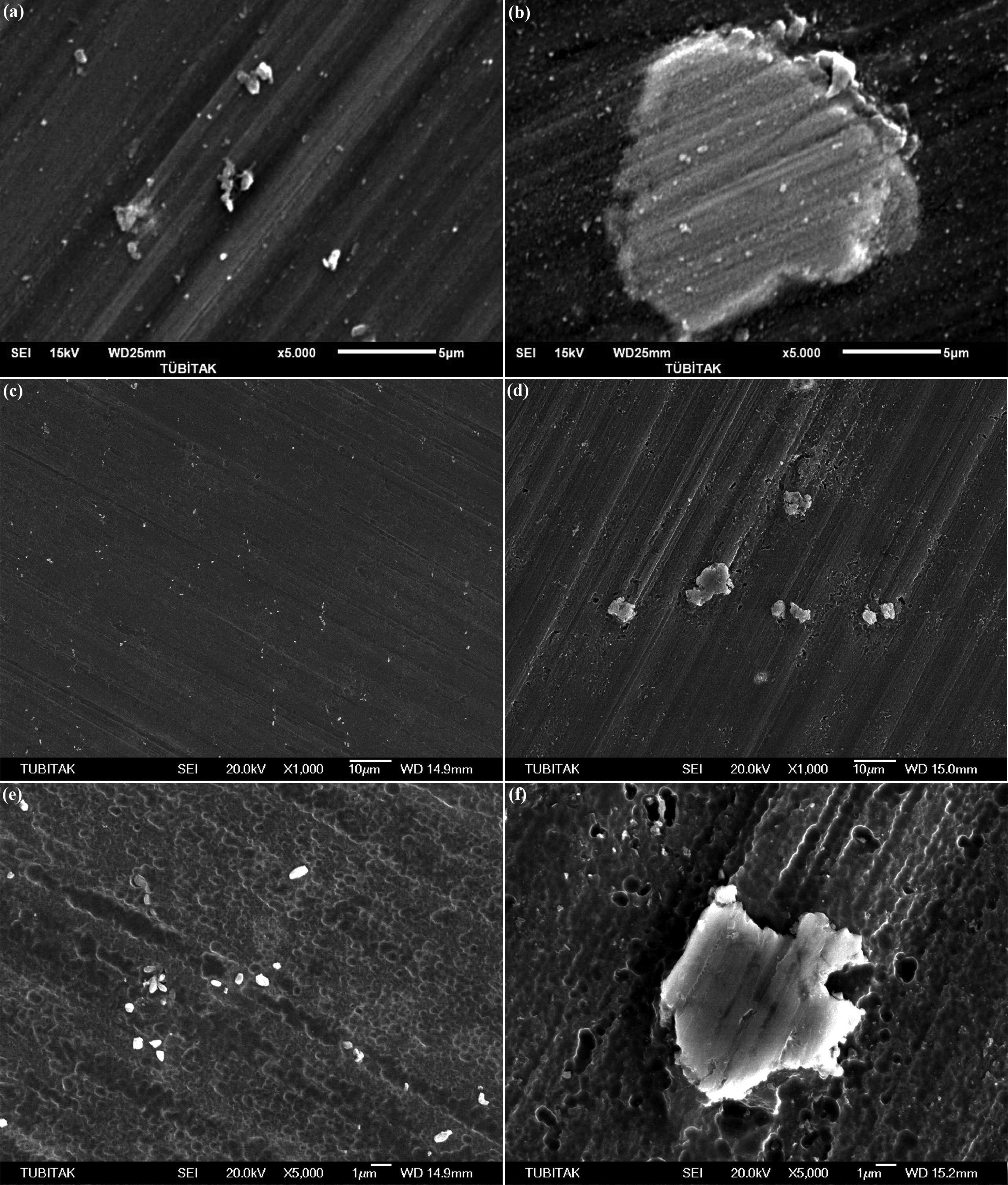
The higher corrosion rate of DCC AZ31 sample in 0.5M Na2SO4 can be explained by considering the size and distribution of Al–Mn particles (Table 2). Normally, the corrosion rate of pure magnesium is low and homogenous in character in sodium sulphate solutions.20,21 However, the presence of intermetallics, which were more cathodic to the substrate, increased the corrosion rate through microgalvanic cells formed between the matrix and the intermetallics. In DCC AZ31, the intermetallics were larger and thus penetrated deeper into the matrix. They stayed longer in their places and continued their cathodic action in the microgalvanic cell for a longer period before falling out. Thus the cavities left behind the fallen out intermetallics in DCC AZ31 were deeper and higher in volume (Fig. 6b). In TRC AZ31 the intermetallics were very small. They easily fell out of their places after the dissolution of their peripheries due to microgalvanic corrosion. Their time of action as cathodes was very low. The pits formed on TRC AZ31 were very shallow and their diameters were very small (Fig. 6a).
Images (SEM) of pits left behind fallen out Al–Mn intermetallics in a TRC and b DCC AZ31 sheets immersed in 0.5M Na2SO4 solution
The corroded surfaces of TRC and DCC AZ31 sheets after the electrochemical tests performed in 0.01M NaCl solution are shown in Fig. 7. Scanning electron microscopy investigations indicated that in 0.01M NaCl solution in addition to pitting, filiform corrosion was also observed. As very well known,7,43 dissolved cations (Mg2+) attracts chloride ions inside the pits. Hydrolysis reaction of MgCl2 gives magnesium hydroxide and hydrochloric acid (HCl) which reduces the pH of the solution inside the pits. These pitting sites permit the acidic solution to penetrate below the oxide film causing filiform corrosion.

Corrosion morphologies of a–d TRC and e–h DCC AZ31 sheets after electrochemical corrosion tests in 0.01M NaCl solution
The major difference in the filiform corrosion behaviour of TRC and DCC sheets are length of the filaments. The lengths of filaments in TRC samples are longer and seem to extend to longer distances (Fig. 7). The results of the study indicated a strong relation of intermetallic size and distribution in the propagation of filiform filaments. In other studies conducted on magnesium alloys in chloride containing environments similar occurrence of filiform corrosion was also observed.15,17,21,44 However, in these studies the role of intermetallics on the propagation of this type of corrosion was not investigated. On the other hand, studies conducted on aluminium alloy filiform corrosion indicated the strong effect of intermetallic size and distribution on the initiation and propagation of filiform corrosion.45–47 Since the intermetallics are the preferential sites for the initiation of pitting, their distribution on the surface is expected to exert an effect on the formation of pits and the propagation of filaments. A schematic presentation for the explanation of the different filiform corrosion behaviour of TRC and DCC sheets, based on the oxide film model of Nordlien et al., 48 is given in Fig. 8. First stage indicates the migration of chlorides into the pitting sites and second stage shows the propagation of filiform corrosion due to the penetration of acidic solution under the oxide film. As presented in the figure, the extension of filaments to higher distance in TRC samples can be related to the presence of the high number of submicrometre intermetallics which act as active sites during the propagation of filiform filaments.
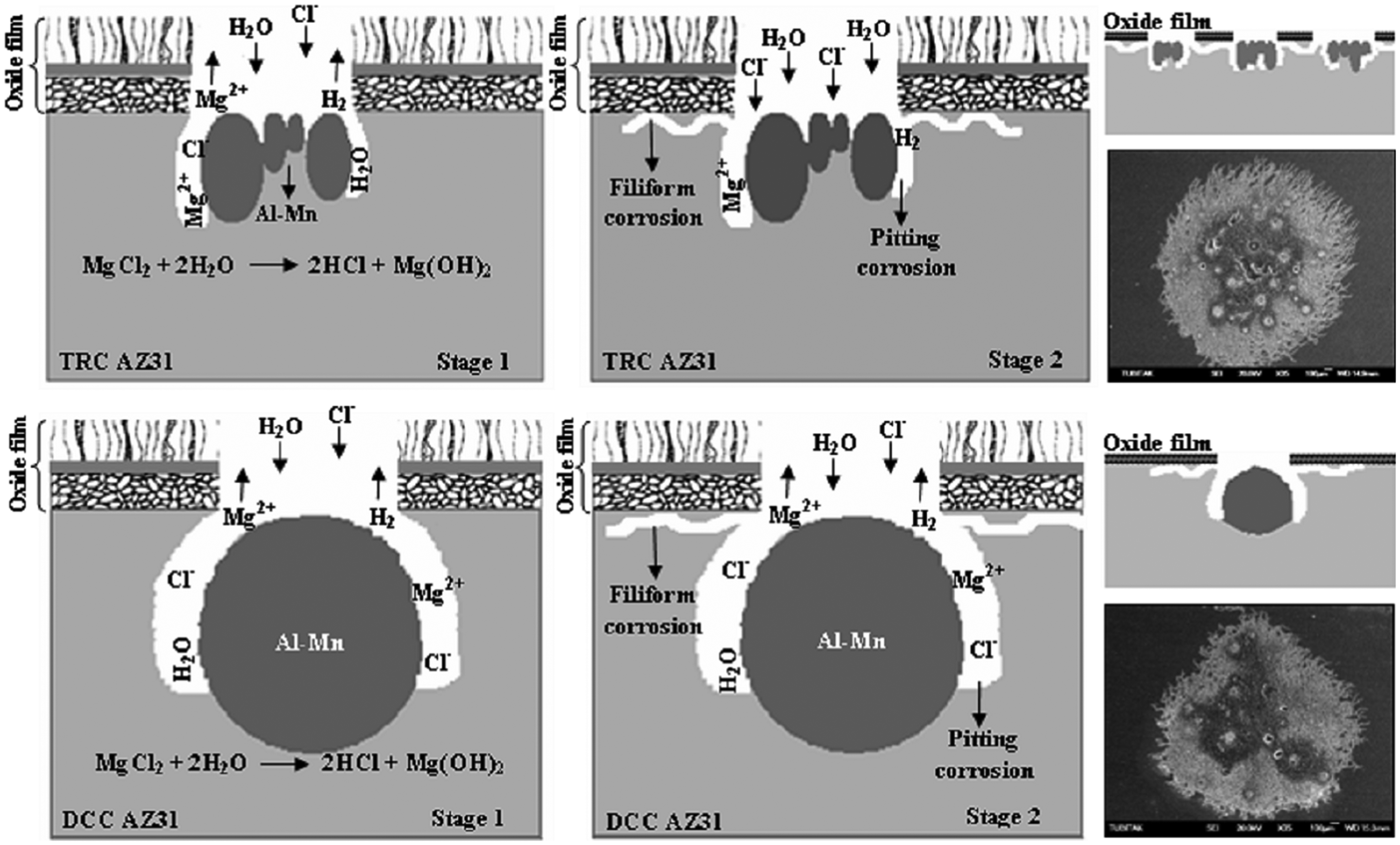
Schematic presentation of propagation of filiform corrosion in TRC and DCC AZ31 sheets in 0.01M NaCl solution
Immersion test results and corrosion morphology
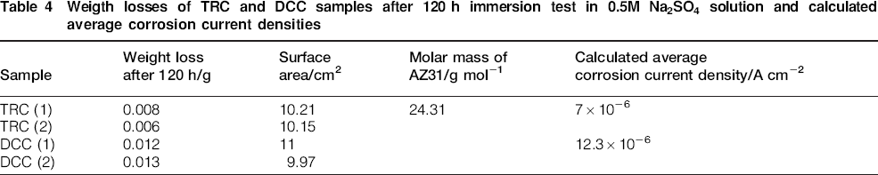
After the immersion tests performed in 0.5M Na2SO4 and 0.01M NaCl solutions, the corrosion rates (i corr) were calculated and surface morphologies were investigated in order to compare with the results obtained in electrochemical corrosion tests. During immersion tests, no appreciable weight losses could be determined till 120 h immersion time both for TRC and DCC samples. Significant differences in weight loss (corrosion rate) became apparent for samples that were subjected to immersion tests for 120 h and beyond (Table 4). Immersion tests carried out in 0.5M Na2SO4 solution indicated that corrosion rates of DCC AZ31 (i corr (120 h) = 12.32×10⁻⁶ A cm−2) sheets were higher than that of TRC AZ31 (i corr (120 h) = 7.10×10⁻⁶ A cm−2) specimens after 120 h. When compared to the results obtained from electrochemical tests the corrosion current densities obtained from weight loss experiments are 10 fold lower (Table 2). This difference can be explained by the limited corrosion protection action of the corrosion products on alloy surfaces that form during long duration tests and due to the accelerated nature of electrochemical tests.
Weigth losses of TRC and DCC samples after 120 h immersion test in 0.5M Na2SO4 solution and calculated average corrosion current densities
Calculated i corr values of TRC sheets (i corr (120 h) = 8.79×10⁻⁵ A cm−2) were higher than that of DCC AZ31 (i corr (120 h) = 2.5×10⁻⁵ A cm−2 specimens after 120 h immersion test in 0.01M NaCl solution.
The planar views of the corroded TRC and DCC AZ31 sheets’ surfaces after the immersion tests performed in 0.5M Na2SO4 for are shown in Fig. 9. Scanning electron microscopy observations of the samples after the immersion test indicated that pitting corrosion occurred around the Al–Mn particles due to microgalvanic effects between the magnesium matrix and cathodic Al–Mn intermetallics. The corrosion morphology obtained after the immersion tests is similar to the results of electrochemical tests (Figs. 5 and 9).
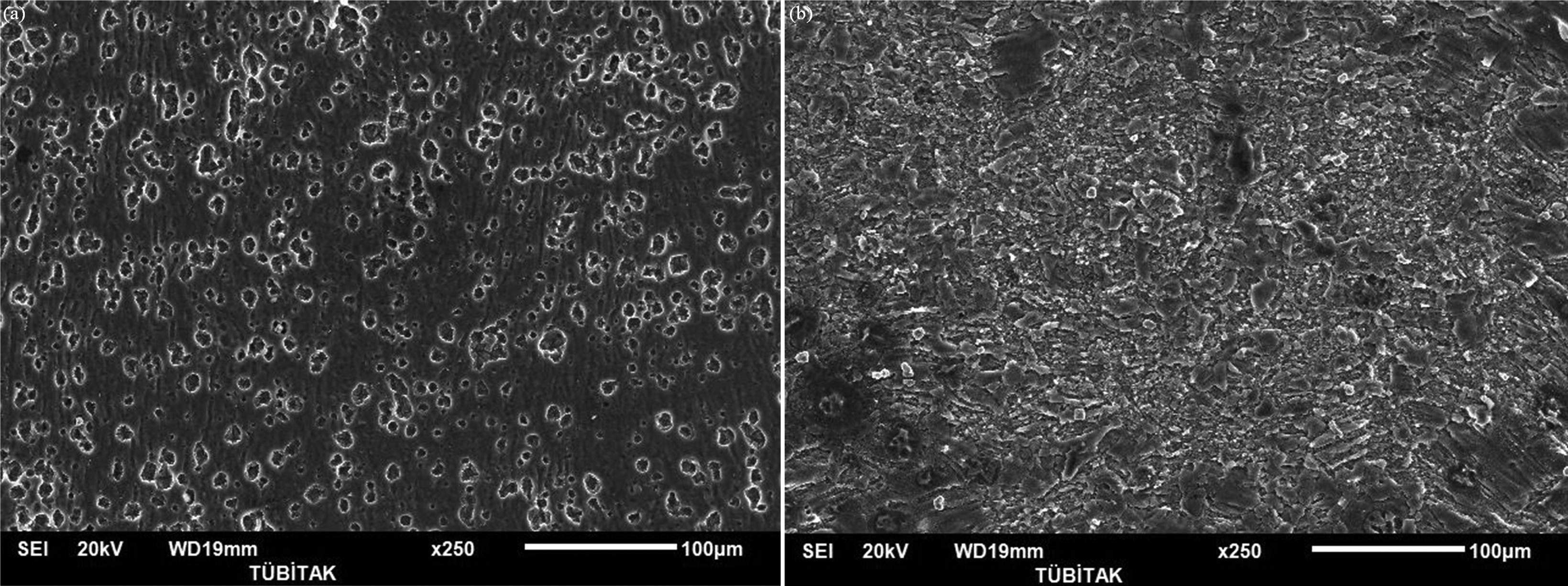
Images (SEM) of a TRC and b DCC AZ31 sheets after immersion tests in 0.5M Na2SO4 solution
The corroded surfaces of TRC and DCC AZ31 sheets after the immersion tests performed in 0.01M NaCl solution (Fig. 10) showed that in addition to pitting, filiform corrosion was also observed and the corrosion morphologies are comparable to the results of electrochemical tests (Figs. 7 and 10).
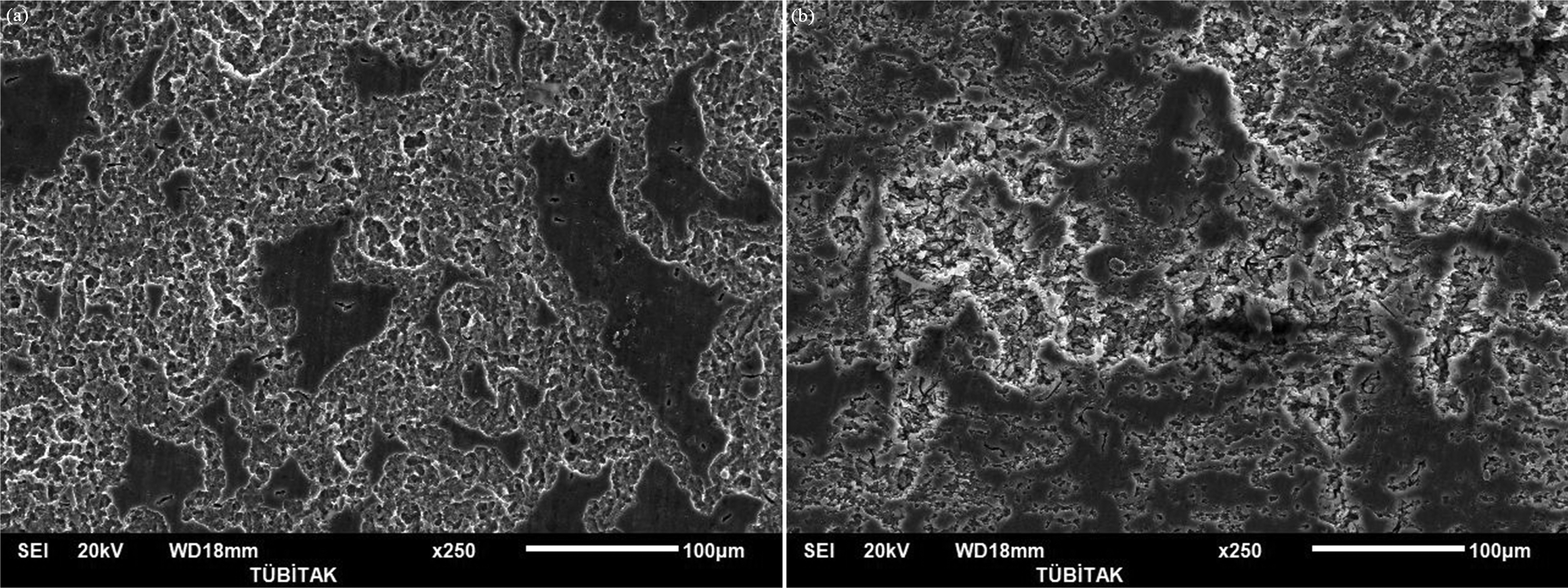
Images (SEM) of a TRC and b DCC AZ31 sheets after immersion tests in 0.01M NaCl solution
Conclusions
Characterisation studies indicated that magnesium AZ31 sheets produced by twin roll strip casting+rolling and DCC+rolling were different in terms of microstructure due to the production methods. The results of this study showed clearly the role of microstructure on the localised corrosion and the possibility of obtaining different localised corrosion behaviour for alloys with similar chemical compositions. In our case for AZ31 magnesium alloys, the size and distribution of intermetallics in the structure showed a dependence on the production method that exerted a strong effect on their corrosion behaviour.
Scanning electron microscope observations of the samples immersed in Na2SO4 and NaCl solutions indicated that localised corrosion occurred around the Al–Mn particles due to microgalvanic effects between the magnesium matrix and cathodic Al–Mn intermetallics.
The results of this study also revealed that, the corrosion rates and surface morphology of TRC and DCC AZ31 sheets after immersion tests are comparable to the results obtained in electrochemical corrosion tests.