
Abstract
In order to investigate and evaluate the corrosion characteristics of steel members more effectively under seawater conditions, the authors have developed an accelerated exposure experimental system to simulate under seawater environments. The acceleration coefficients of this experimental system were based on a study of the depths of corrosion actually found in structural steel members exposed to seawater environments for over 19 years. The accelerated coefficient for the splash zone was around 6·0. In the experiment reported, the system was used to investigate the corrosion behaviours of steel coated with epoxy resin, polyurethane resin and tar-epoxy resin and then subjected to damage from cross scribe lines or circular types of coating defect. Corrosion propagation was found to occur under the coating around the boundaries of these coating defects and macrocell corrosion was observed around the boundary areas. Methods of predicting corrosion propagation distances under the organic coating and the depths of corrosion under the coating defects were proposed based on the experimental results.
Introduction
A great amount of infrastructure was constructed in Japan in the period of high economic growth from the 1950s to the 1970s. Many of the structures have aged and deteriorated and the management of deteriorated infrastructure is now a daunting problem from the viewpoints of both engineering and economics. In the case of steel structures in marine and coastal areas, a major cause of deterioration is seawater corrosion. A high proportion of the underwater steel piers and sheet piles used in shore protection works are reported to be corroded.1,2 The corrosion behaviour is difficult to predict, however, as it has a complicated dependence on the seawater conditions in each case. Furthermore, corrosion in underwater members is hard to detect and monitor. To counter these difficulties, it is important from the point of view of maintenance to have the best possible grasp of the corrosion behaviour of steel structural members in this kind of seawater environment.
A standard method proposed by the Japanese Society of Civil Engineers for the investigation and evaluation of the corrosion characteristics of steel members in undersea environments is through the use of an accelerated exposure experiment. 3 Using this standard method, 16 steel plate specimens of the dimensions 150×70×10 mm can be tested at once. To further enhance the effectiveness of this method, a larger-scale accelerated exposure experimental system based on the standard one has been developed by the authors with a testing capacity 6 times that of the standard one. To assess the performance of this newly developed experimental system, a series of accelerated exposure experiments have been carried out on steel plate specimens without protective coatings.
In general, several methods are used to prevent corrosion in steel structural members in seawater environments. These include cathodic protection, organic coating or petrolatum coating, the choice depending on the position in relation to the water level as well as the empirical effectiveness of each method. Organic coatings are generally applied around the splash zone where the corrosion conditions are most severe. Reports have been published of the long term performances of organic coated steel members in actual seawater environments 4 and from these as well as from general experience, corrosion is known to occur especially around parts of the coating that have been damaged by wave action or driftage impacts.
Although the importance of investigating the performances of organic coatings in the actual sea environment is well understood by those concerned with the maintenance and management of infrastructure, it imposes an enormous cost in time and resources. This explains the general reliance on an accelerated exposure experimental system simulating seawater conditions, mentioned above, which is also used for the testing of organic coated steel specimens in this study. The types of organic coating tested are epoxy resin paint, polyurethane resin paint and tar-epoxy resin paint, which are all employed to prevent corrosion in steel members in seawater environments. Two forms of artificial initial defects are also studied: cross scribe lines and circular defects of three different diameters. 5 Based on the experimental results, corrosion behaviours in the steel specimens are investigated in connection with each of the two types of initial defect in the organic coating. Methods are then proposed for the prediction of these corrosion behaviours.
Accelerated exposure experiment simulating seawater environment
Experimental system
Figure 1 gives an overall view of the newly developed accelerated exposure experimental system simulating the seawater environment. The tank, of dimensions 760×710×350 mm, is filled with salt water (3% NaCl, 50 degrees Celsius, 120 L). Plate specimens measuring 150×70 mm with a thickness of up to 10 mm are set on acrylic stands in the bottom and air (2·0 L min−1) is bubbled up from hoses below the stands to generate a water circulation and maintain the density of dissolved oxygen. These conditions are kept constant over the 28 days of one testing cycle to achieve a controlled acceleration in the corrosion of the steel specimens. 3 The testing capacity of this new experimental system is thus 6 times as large as that of the standard one. 3 Using this system, a maximum of 96 specimens can be set up for testing at one time.

a forms and dimensions of experimental system; b appearance of experimental system
At the end of one 28-day cycle, the specimens are removed from the tank, an inspection is made of their surface appearance and the reduction in thickness is measured. The salt water is then replaced for the next cycle and the specimens are reinserted in changed positions to eliminate the possible influence of the set-up position on the rate of corrosion. The experimental periods chosen for this study were of 28 days (1 testing cycle), 84 days (3 cycles) and 168 days (6 cycles).
Specimens
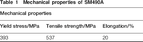
The specimens used in this study were of a general structural carbon steel (JIS SM490A). 6 The chemical composition of SM490A is 0·16C–0·01Si–0·84Mn–0·15P–0·05S (wt-%). Table 1 shows mechanical properties of SM490A. The specimen dimensions were 150×70×6 mm.
Mechanical properties of SM490A
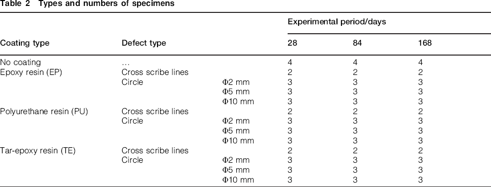
The types and numbers of specimens are shown in Table 2. The specimens without protective coatings served as a reference base. The surface of these non-coated specimens was cleaned by blasting, but a region 5 mm from the four edges of the surface was coated with epoxy resin to protect a set of measurement positions from corrosion during the experiment. These were the standard points used after each test cycle to measure the depth of corrosion. The back of the specimen which was not intended to be subjected to the corrosive bubbling attack was coated with anti-corrosion tape.
Types and numbers of specimens
Three types of organic coating were applied to the steel test specimens: epoxy resin paint (EP), polyurethane resin paint (PU) and tar-epoxy resin paint (TE). All three are widely used for the prevention of corrosion in steel members in undersea environments. Table 3 shows the specifications of each type. In addition, two forms of artificial initial defects, cross scribe lines and circles of three different diameters, were worked into the coated specimens. Figure 2 shows the two types of initial defect on the coated specimens. The cross scribe and circular defects simulate scratch and impact marks caused by driftage, while the steel substrate region in the cross scribe specimen simulates the boundary between the coated and non-coated parts of steel members. The cross scribe and circular defects were added with an end mill after coating. The steel substrate region was created by attaching a length of masking tape to the substrate steel before coating and removing it again afterward. These specimens are of types used by the authors in previous research.5,7
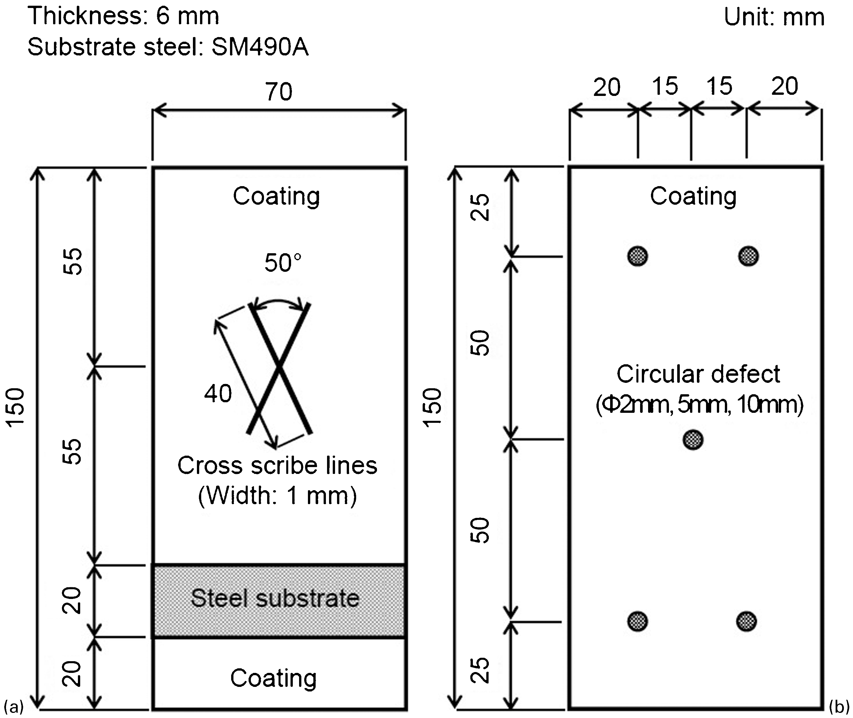
a cross scribe specimen; b circular defect specimen
Organic coating specifications
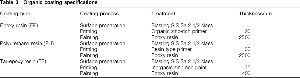
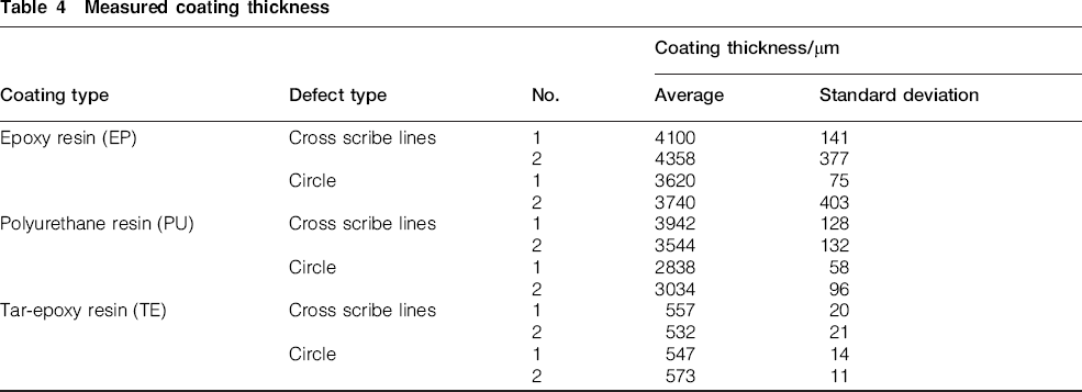
Table 4 shows the coating thickness of four specimens in each organic coating type with different defect types. The average and the standard deviation of coating thickness was measured from 9 points in one specimen.
Measured coating thickness
The accelerated exposure experiment was started over 3 months later after finishing the coating of specimens.
Corrosion behaviour of steel specimens without coating
Surface appearance
Figure 3 shows the surface appearances of non-coated specimens at the end of each experimental period. Red rust was observed at the surface of the specimens. Brown and black rust from the substrate steel was also observed in some parts where the surface red rust had been removed by the water flow.
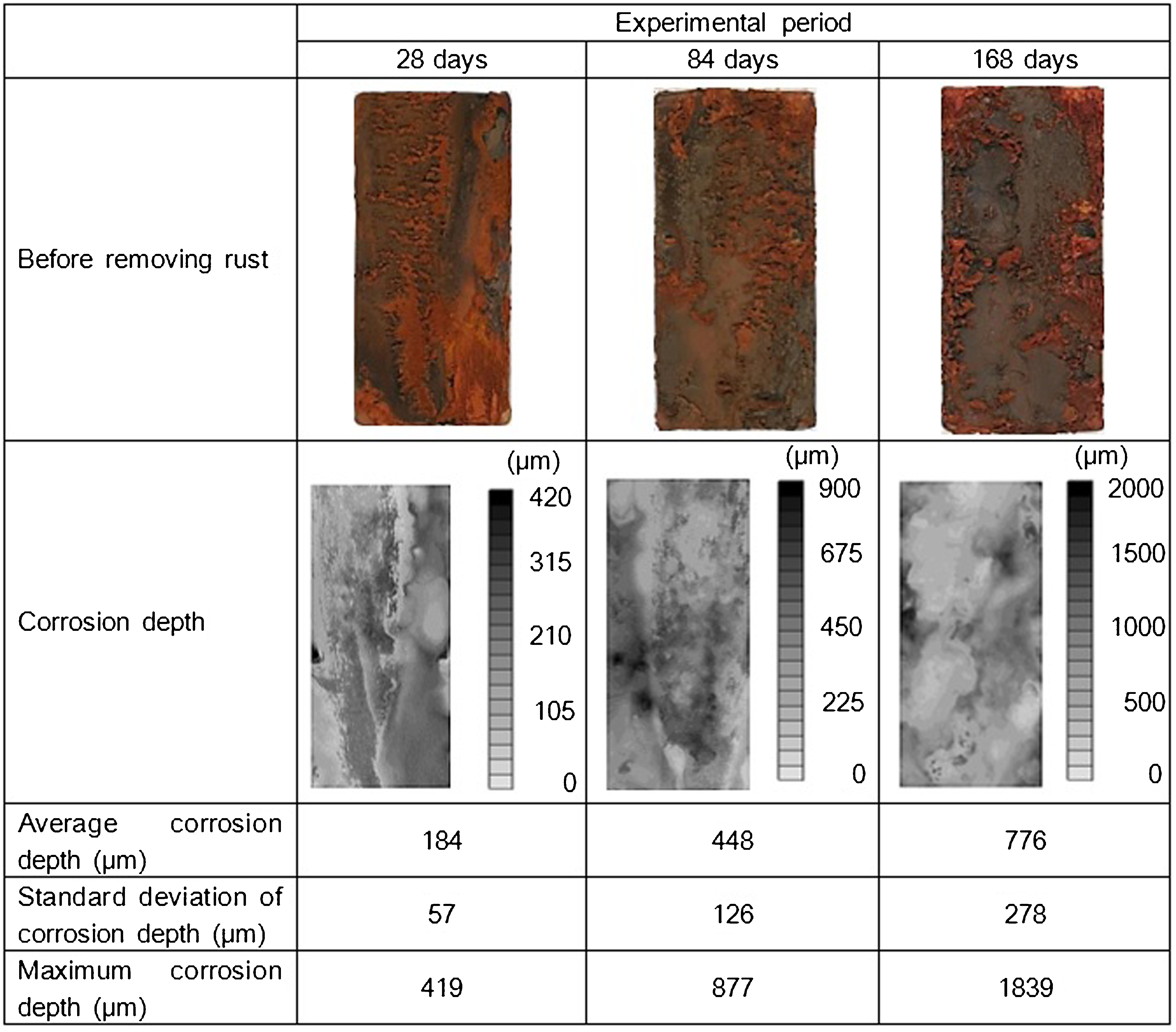
Appearance and corrosion depth of specimens
After removing the rust by blasting with aluminium powder, the shape of the specimen surface was measured using a laser displacement meter. The interval between each pair of measurement points was 0·3 mm in both the longitudinal and the transverse directions. The corrosion depth was measured as the difference in height from the three standard points in the coated region at the edges of the specimen where no corrosion was deemed to have occurred during the experiment. The corrosion depth in places where rust had been removed by the water flow was found to be greater than in other more uniformly corroded parts.
Corrosion depth
Figure 4 shows the corrosion depth observed in non-coated specimens at the end of each experimental period. The increase in the corrosion depth is almost linearly proportional to the number of experimental cycles, except that the rate of increase falls off slightly with each increase in the number of cycles. The reason for this is that the accumulated layer of existing rust protects the surface of the specimen against further oxidisation.
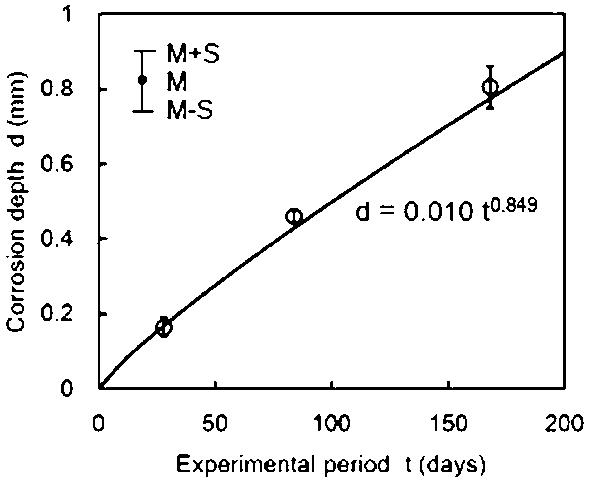
Relationship between corrosion depth and experimental period
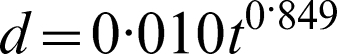
The curve here describes a power regression function of the corrosion depth expressed by equation (1). This function is of the same type as in the non-linear model of corrosion for steel structures in marine environments proposed by Melchers.
8
The correlation coefficient of the regression curve is 0·99. The results indicate that depths of corrosion in non-coated specimens can be predicted from this regression curve
Accelerated coefficient
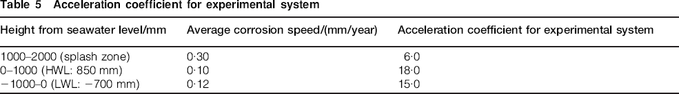
The average corrosion rate over 168 days was found from this experimental system to be 1·8 mm/year. This can be compared with reported Japanese results of the actual average rate of corrosion in non-coated steel members exposed to the sea for a period of 19·5 years. 9 Table 5 shows the relationship between this actual average rate of corrosion and that obtained from the experiment. Based on this, the accelerated coefficients of this experimental system for the splash zone and the areas around the high and low water levels are found to be 6·0, 18·0 and 15·0, respectively.
Acceleration coefficient for experimental system
Corrosion behaviour of organic coated steel specimens
Surface appearance
Figure 5 shows the surface appearances of organic coated specimens at the end of each experimental period. The surfaces were lightly blasted to remove the rust from the coatings. Red rust was generated around each coating defect. The longer the experiment, the greater the quantity of red rust adhering to the specimen surface.
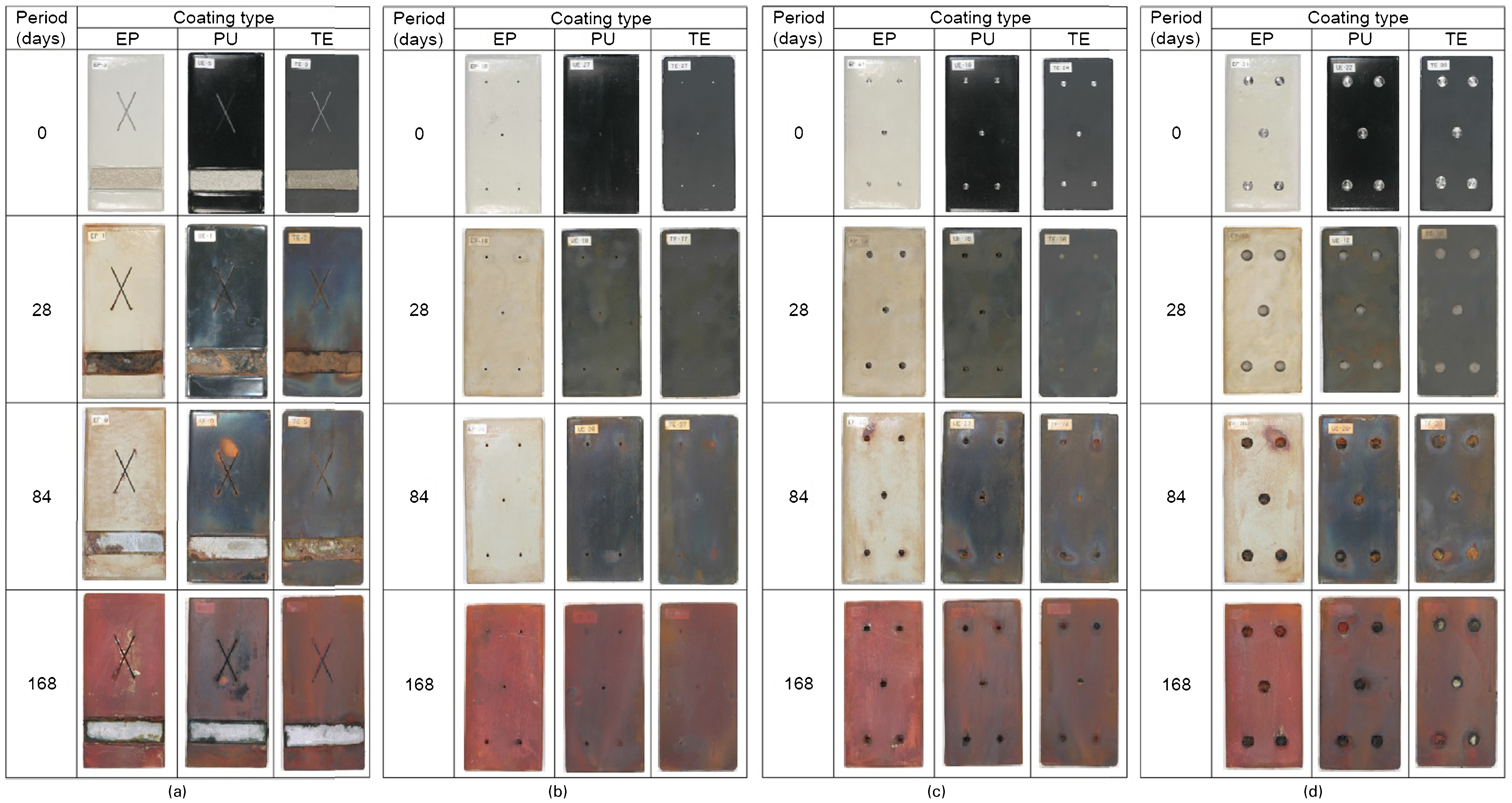
a cross scribe specimen; b circular defect specimen (φ2 mm); c circular defect specimen (φ5 mm); d circular defect specimen (φ10 mm)
Surface shape
After removing the organic coatings by dipping the specimens in acetone, the surface shape of the specimens was measured using a laser displacement meter in the same way as for the non-coated specimens. Figure 6 shows the results of this for a cross scribe specimen and a circular defect specimen, both with a TE type coating, after an experimental period of 168 days.
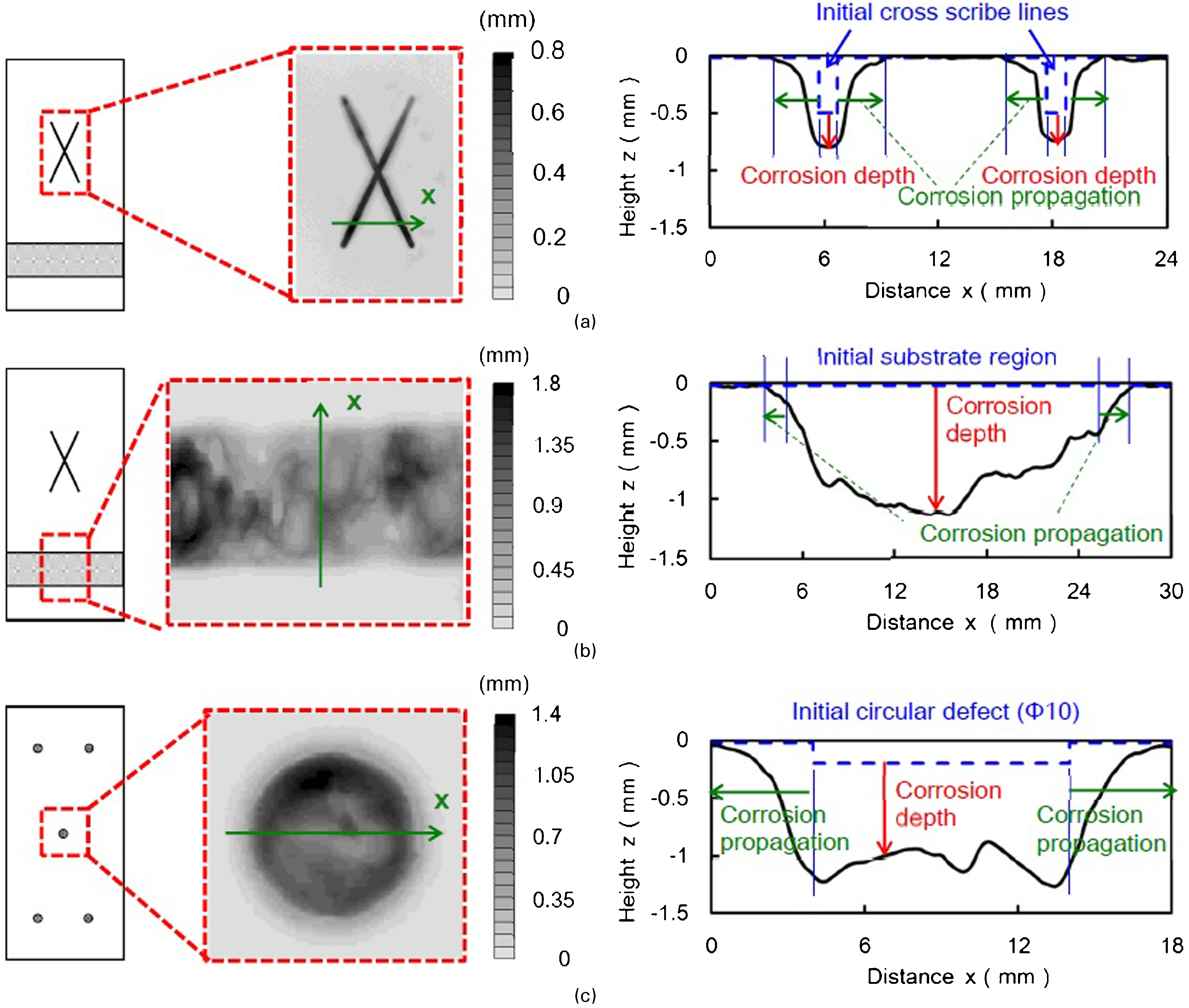
a cross scribe lines; b substrate steel region; c circular defect (φ10 mm)
These results confirm that some propagation of corrosion takes place under the coating around the edges of each defect. In the case of circular defect specimens, macrocell corrosion was also observed around the defect boundary. That is to say, the defect part became the anode and the coated region around the defect became cathode. Therefore, the corrosion current concentrated around the defect boundary. As a result, the corrosion was accelerated around the edges rather than at the centre of the defect.
Corrosion propagation distance
Measurements were made of propagations of corrosion out from the edges of each surface defect. Figure 7 shows the distance measurements for each type of defect. For cross scribe lines, propagation distances were measured left and right of nine reference lines drawn around the cross scribe. For the substrate steel region, they were measured above and below five lines drawn along the substrate. For circular defects, they were measured along eight lines radiating out from the defect. Figure 8 shows the relationship between average propagation distances and the lengths of the experimental periods. No corrosion propagation appears up to a certain point in the experimental period, but from that point on, propagation sets in and gradually increases.
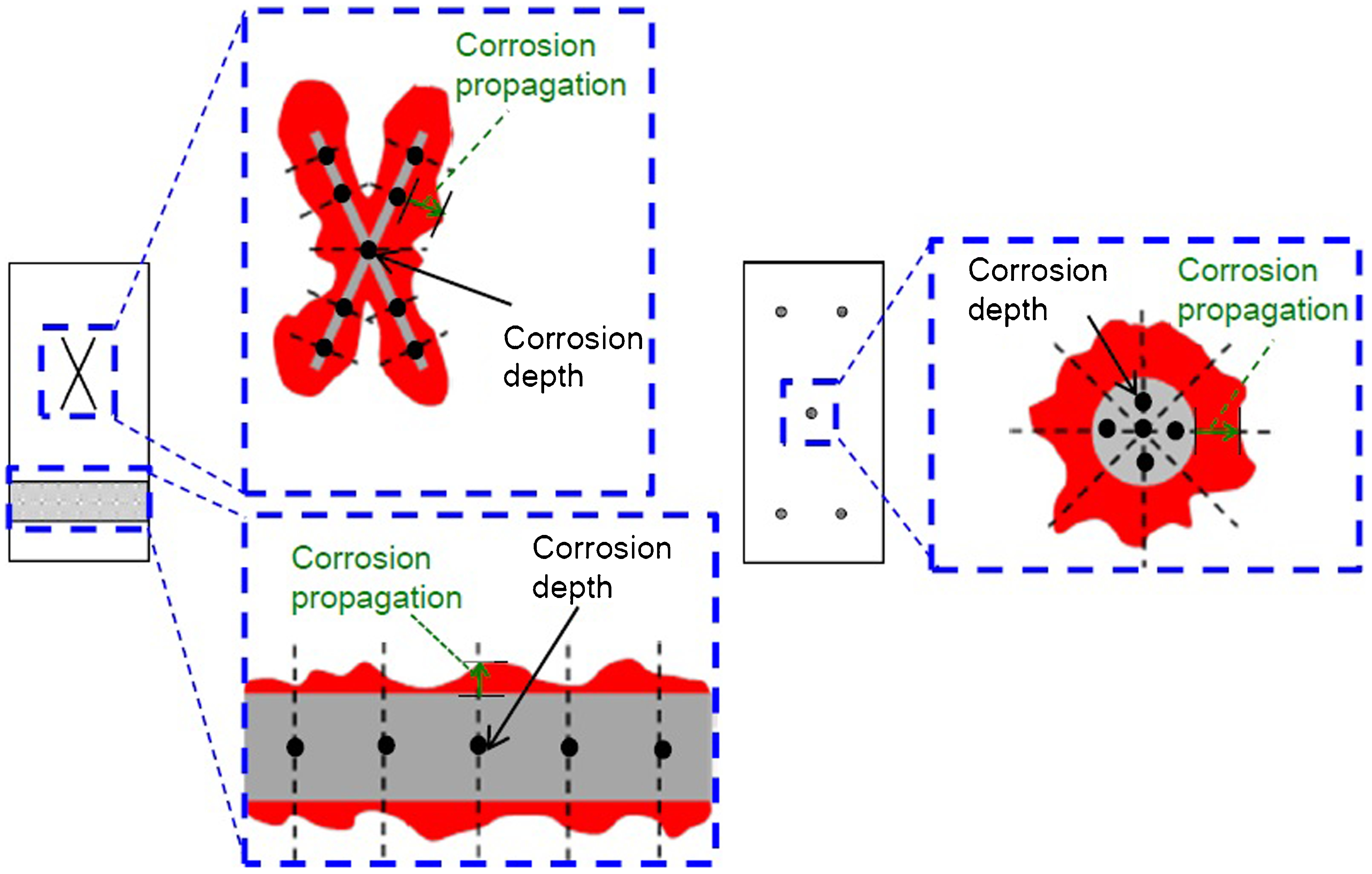
Measurement positions for corrosion propagation distance and corrosion depth
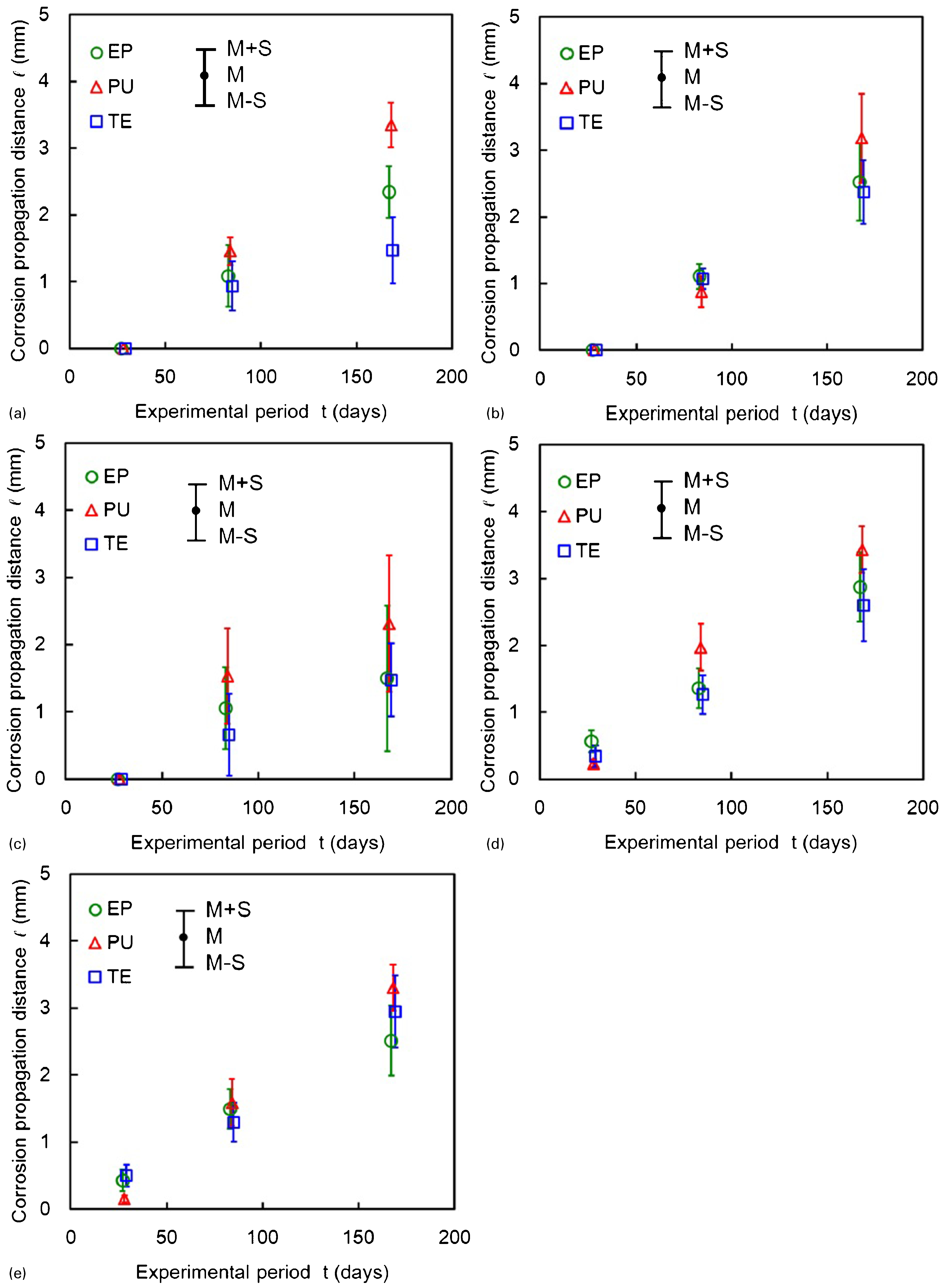
a cross scribe lines; b substrate steel region; c circular defect specimen (φ2 mm); d circular defect specimen (φ5 mm); e circular defect specimen (φ10 mm)
A certain tendency was confirmed for corrosion propagation distances in each defect category to be greater in the PU specimens than in specimens with other organic coatings. There was little difference in this respect between EP and TE specimens. The reason may lie in the difference in the priming material. A zinc-rich paint or primer might offer more resistance than a resin type one to corrosion propagation beneath the primer. 10 Although the coating thickness of the PU specimens were around 6 times as large as that of the TE specimens, the corrosion propagation distance of the PU specimens was larger than that of the EP specimens. The result indicated that the priming material strongly affected the corrosion propagation of the coated steel rather than the coating thickness.
This variation among the coating types with regard to corrosion propagation distances also seems to have a certain dependence on the size of the defect. In the substrate steel region and for circular defects with diameters of 5 and 10 mm, the propagation distances were almost the same for each type of organic coating. However, around cross scribe lines and for circular defects of diameter 2 mm, the differences in the propagation distances among the three coating types were greater than in the other defect categories.
Corrosion depth
The corrosion depths for the various types of defects were measured at the points shown in Fig. 7, that is to say, at 9 points around the cross scribe lines, at 5 points along the substrate steel region, and at 5 points in each circular defect. Figure 9 shows the corrosion depths found for each defect type. The relationship reported in chapter 3 (equation (3)) between corrosion depth and the experimental period is shown again here by a solid line.
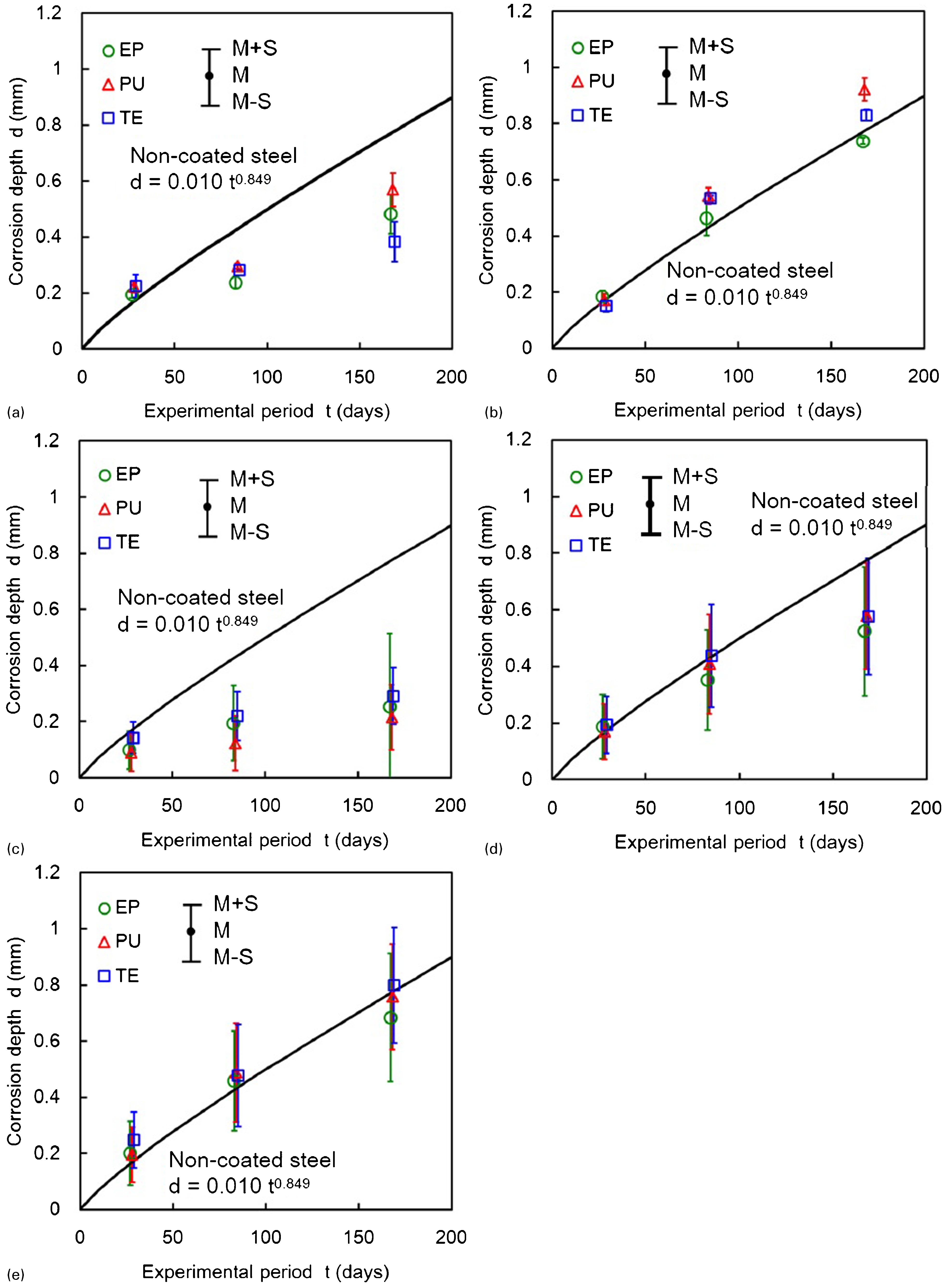
a cross scribe lines; b substrate steel region; c circular defect (φ2 mm); d circular defect (φ5 mm); e circular defect (φ10 mm)
With regard to corrosion depth, there was little difference among the three coating types in any of the defect categories. However, when defect size was taken into account, the corrosion depths occurring with cross scribe lines and with small circular defects of diameter 2 or 5 mm were smaller than those found in non-coated steel. The corrosion depth with cross scribe lines was around 61% of that for non-coated steel for an experimental period of 168 days. For the same period, corrosion depths for circular defects of diameter 2 and 5 mm were around 32 and 72% of the depth for non-coated steel, respectively. In the cases of the substrate steel region and of circular defects with a diameter of 10 mm, the corrosion depths were almost the same as for non-coated steel. It seems therefore that the size of a coating defect affects the depth of corrosion. In the findings of this study, a substrate steel region with a width of 20 mm and a circular coating defect with a diameter of 10 mm appear to leave no protection against corrosion.
Prediction of corrosion behaviour of organic coated steel
Prediction of corrosion propagation distance
From the viewpoint of the maintenance and management of organic coated steel structural members in a seawater environment, the ability to predict the propagation of corrosion under the coating is important because it is a difficult phenomenon to investigate from outside the coating. A feasible prediction method is proposed here based on the experimental results.
As shown in Fig. 8, there were some differences in the corrosion propagation distances depending on the type of coating. In addition, these differences were greater in the cases of cross scribe lines and circular defects of 2 mm diameter than they were in the substrate steel region or in circular defects with diameters of 5 or 10 mm. Therefore, separate treatments are needed for the prediction of corrosion propagation distances from relatively small initial defects (cross scribe lines and circular defects of diameter smaller than 5 mm) and those from larger defects (the substrate steel region and circular defects of 5 mm diameter or over).
Another problem is the macrocell corrosion which seems to occur in the steel around the edges of coating defects. 11 If it occurs, this is a situation that will persist even over longer experimental periods. It is also conceivable that the corrosion propagation under the organic coating corresponds to the initial corrosion stage of the steel. The initial corrosion behaviour of ship structures as proposed in the extended Southwell bilinear model 12 and the Melchers trilinear model 8 is given by a linear function. This might account for why the corrosion propagation distances under the organic coating in this study are approximated by linear regressions.
Figure 10 shows linear regression lines for corrosion propagation distances measured from defects smaller in size than 5 mm (cross scribe lines and a circular defect of diameter 2 mm) and from defects of size 5 mm or above (the substrate steel region and circular defects of diameters 5 and 10 mm). The respective linear regression lines can be represented by the following equations. For a defect size smaller than 5 mm (cross scribe lines or a circular defect of diameter 2 mm)


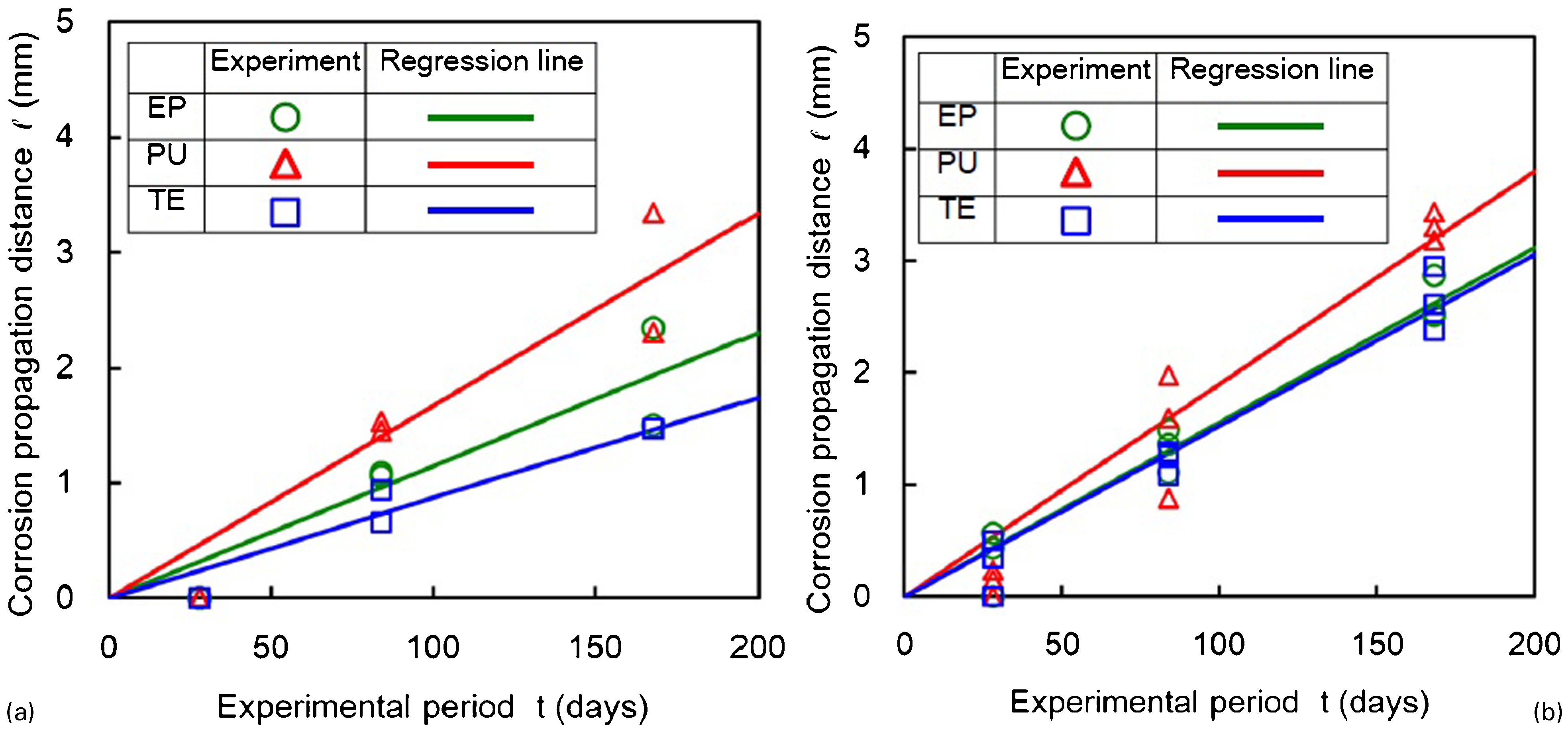
a defect size smaller than 5 mm; b defect size of 5 mm over
The correlation coefficients of these regression lines are over 0·92. The equations can therefore be said to give a good prediction of the corrosion propagation distances for each type of organic coating if account is taken of the size difference in the defects. Moreover, the time periods tested for in the accelerated exposure experiment can be correlated with those measured in actual seawater conditions by using the kind of acceleration coefficients shown in Table 5. In other words, the periods obtained from the experiment can be converted to actual periods by multiplying them with the acceleration coefficients specific to each seawater environment.
Prediction of corrosion depth
The prediction of corrosion depth in organic coated steel structural members is also of great importance because the resulting reduction in thickness directly affects the structural performance. A method for the prediction of corrosion depth around coating defects can be proposed here based on the experimental results.
As shown in Fig. 9, corrosion depths remained almost the same irrespective of the type of coating. However, various differences appeared depending on the size of the defect. Accordingly, while there is no need to consider the coating type when predicting corrosion depth, each type of defect does need to be treated separately, except that the depth of corrosion in circular defects of diameter 10 mm or above and in the substrate steel region will be almost the same as in steel without a coating. The corrosion depth in these two cases can be approximated by a power function 8 just it can as in the case of non-coated steel.
Figure 11 shows the power regression curves for the depths of corrosion found with each defect type. The functional shapes of the respective regression curves are shown by the following equations


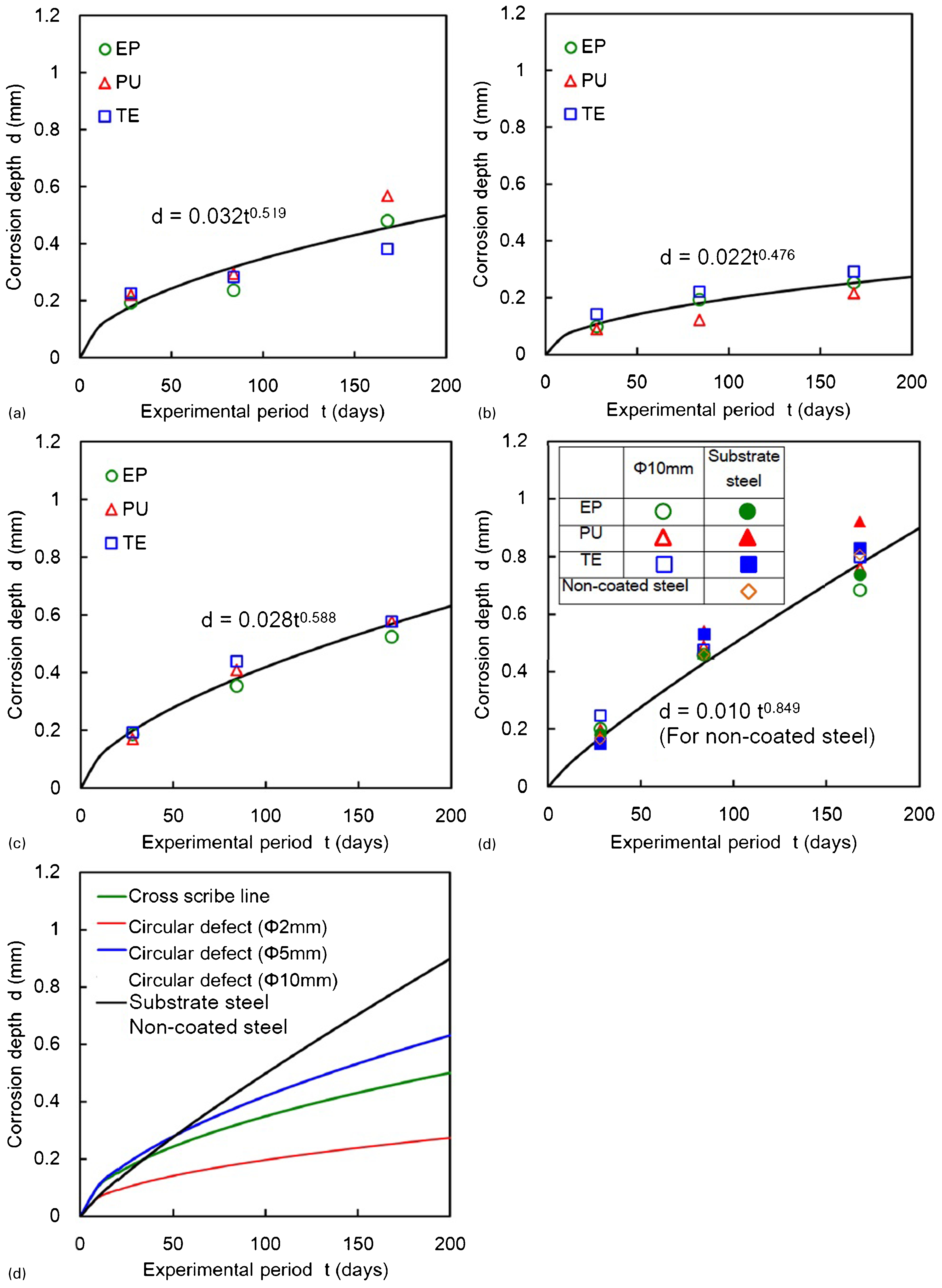
a cross scribe lines; b circular defect (φ2 mm); c circular defect (φ5 mm); d circular defect (φ10 mm), substrate steel region and non-coated steel; e comparison of regression curves
Comparing all of these regression curves together as in Fig. 11e, the corrosion depths found with relatively small coating defects such as cross scribe lines or a circular defect of diameter 5 mm are larger than for non-coated steel in the initial stage. The reason for this might be the relatively large influence of macrocell corrosion in the initial stage of coating deterioration. As corrosion progresses with the increasing number of experimental periods, the depth of corrosion from these smaller defects falls behind that occurring in non-coated steel because of the decrease in this influence from macrocell corrosion.
In just the same way as for the corrosion propagation distances under the coatings, the periods of the accelerated exposure experiment can be converted to actual time periods by multiplying with the acceleration coefficients for the particular seawater environment as shown in Table 5.
Conclusions
The authors have developed an accelerated exposure experimental system to enable the corrosion characteristics of steel members to be effectively investigated and evaluated in seawater conditions and have used this system to examine the corrosion behaviour of organic coated steel affected by several types of coating defect. Corrosion behaviour prediction methods were proposed based on the experimental results.
The main results obtained were as follows.
The corrosion behaviour of steel without a coating was first investigated. It was found that the depth of corrosion obtained using this experimental system could be approximated by a power functional regression curve.
The acceleration coefficients of the system were derived from a comparison with actual results for corrosion depths in steel structural members exposed to a seawater environment for over 19 years. The accelerated coefficients obtained in this way for the splash zone and for areas around high and low water level were 6·0, 18·0 and 15·0, respectively.
Accelerated exposure experiments were performed on specimens of steel with organic coatings of EP, PU and TE including some with cross scribe line defects or circular defects of three different diameters. It was confirmed that corrosion propagation occurred under the coatings around the boundaries of the coating defects. Macrocell corrosion was also observed around the defect boundaries.
The corrosion propagation distance with PU specimens was greater than with EP and TE specimens because of a difference in the priming material. In addition, this difference between the coating types was greater for cross scribe lines and for circular defects of diameter 2 mm than in the substrate steel region and for circular defects of diameter 5 or 10 mm.
While variations in corrosion depth were small between one organic coating type and another, some differences appeared depending on the defect size. The corrosion depth found with a cross scribe line defect was around 61% of that found in non-coated steel for an experimental period of 168 days. For the same period, the corrosion depths with circular defects of diameter 2 and 5 mm were around 32 and 72% respectively of the depth for non-coated steel. In the substrate steel region and with circular defects of diameter 10 mm, the corrosion depths were almost the same as in non-coated steel.
Linear regression lines for the corrosion propagation distances under the organic coating were proposed for each type of coating, also taking account of the different sizes of coating defects. Similarly, power functional regression curves of corrosion depth were also proposed for the different types of coating defect, regardless of the coating type. The practicability of predicting corrosion behaviour through the combined use of these regression curves and the accelerated coefficients of this experimental system was indicated.
Acknowledgement
Some parts of this research were supported by the Japan Iron and Steel Federation.