
Abstract
The present research investigated the effect of H2S/CO2 partial pressure, sulphur deposition and corrosion inhibitor on the corrosion behaviour of L360QCS pipeline steel in H2S/CO2 environments by immersion tests, scanning electron microscope analysis and electrochemical measurements. The results show that the corrosion rate (CR) of L360QCS steel decreased first and then increased with increasing p H2S and p CO2.The CR is closely associated with the protectiveness of corrosion film. Sulphur deposition can cause an acceleration of the corrosion of steel in H2S/CO2 environments. Furthermore, the CR increased obviously with increasing p H2S and p CO2 in sulphur deposition environments. After addition of continuous corrosion inhibitor, the CR decreased significantly in H2S/CO2 environments. Prefilming corrosion inhibitor could enhance the inhibition effect in the presence of continuous corrosion inhibitor.
Keywords
Introduction
As more and more aggressive oil and gas fields with considerable amount of H2S and CO2 gas have been discovered, the corrosion problem of pipeline steel has attracted more attention.1–4 It is generally acknowledged that severe general and localised corrosion of steel are prone to appear in CO2 environments.5–7 In addition, the presence of H2S would cause hydrogen induced cracking and sulphide stress corrosion cracking of pipelines.8–10 Based on aforementioned analysis, it can be recognised that H2S/CO2 corrosion possesses great threat to the safety of pipeline steel in service. Therefore, it is necessary to investigate the corrosion behaviour of steel in H2S/CO2 environments, which is valuable for materials section and safety guarantee of steel in service.
During the past decade, many researchers have focused on the H2S/CO2 corrosion of steel. According to Li et al., 11 the corrosion rate (CR) of 110S tube steel decreased first and then increased with increasing temperature. The minimum CR appeared at 110°C. Yin et al. 12 studied the corrosion behaviour of SM 80SS tube steel in stimulant solution containing H2S and CO2. Corrosion attacks increase in the initial stage and then decrease with the increase in p CO2 or p H2S, and serious corrosion appears in the p CO2/p H2S range from 31 to 520. In addition, localised corrosion of steel in H2S/CO2 environments was also investigated in the previous work. Zhao et al. 13 investigated the corrosion behaviour of two types of Ni based alloys (UNS 06985 and UNS 08825) in 15 wt-% NaCl solution containing H2S/CO2. It showed that the pitting resistance of nickel alloy UNS 06985 was superior to UNS 08825. The temperature was the crucial factor that influenced not only the characteristics of corrosion films but also the CR of the alloys. The results presented by Zhang et al. 14 revealed that obvious pitting corrosion could be prone to occur at 30°C compared to 60°C, 90°C and 120°C. According to Ren et al., 15 general CR decreased slowly and pitting became slight with increasing partial pressure of H2S due to the presence of primary compact and continuous corrosion scale (FeS1+x ). Based on the aforementioned investigations, though some important results have been obtained, most of the studies were performed under low partial pressure of H2S and CO2. As Sichuan sour gas field containing high total pressure of corrosion gas in China develops, it is necessary to the corrosion behaviour of steel in corrosion environments containing high pressure of H2S and CO2. Furthermore, few research studies have been carried out on the influence of sulphur deposition and corrosion inhibitor on the corrosion behaviour of steel.
Based on aforementioned insights, this work evaluated the effect of H2S/CO2 partial pressure, sulphur deposition and corrosion inhibitor on the corrosion behaviour of L360QCS steel exposed to H2S/CO2 environments by immersion tests, scanning electron microscope analysis and electrochemical measurements.
Experimental
Material and specimen preparation
Specimens used in this work were cut from a tube of L360QCS pipeline steel, with a chemical composition (wt-%) of 0·16 C, 0·45 Si, 1·65 Mn, 0·003 S, 0·02 P, 0·07 V, 0·05 Nb, 0·04 Ti and Fe balance. The steel used in this study has a yield strength (σys) of 440 MPa, ultimate tensile strength of 520 MPa and total elongation (δ0) of 35%. For microstructural observations, the specimen surface was grinded with 2000 grit carbide silicon paper and polished with 1·2 μm diamond paste. They were then degreased with acetone and etched with nital solution (a mixture of 5% nitric acid and ethanol). An optical microscope was used to characterise the steel microstructures. Figure 1 shows the optical microstructure of L360QCS pipeline steel. The microstructure of the as received steel contains ferrite and pearlite.
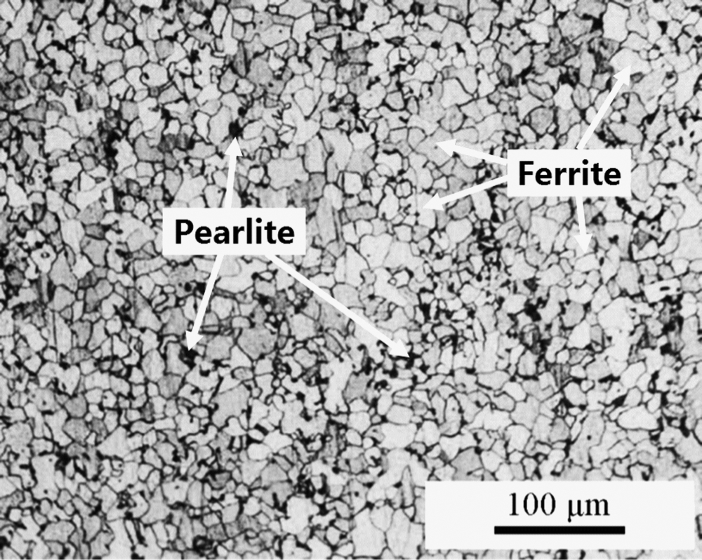
Microstructure of L360QCS pipeline steel
Specimens were cut into 50 × 10 × 3 mm for weight loss tests. For the electrochemical measurement, the specimens were machined to a disc with 8 mm in thickness and 12 mm in outer diameter. Before the experiments, all specimens were ground with 1000 grit carbide silicon paper and degreased with acetone, cleaned with distilled water and dried in air.
Immersion tests
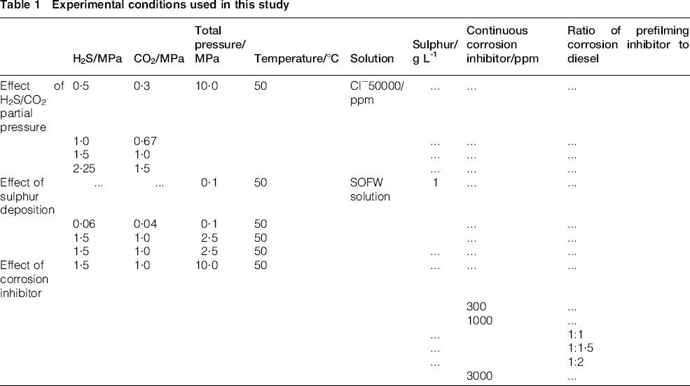
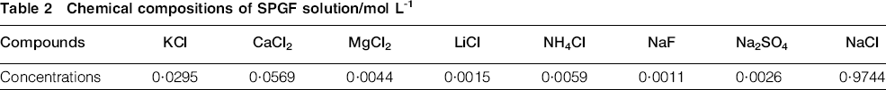
The high temperature and high pressure immersion tests were carried out using an autoclave made by Cortest Company in America. Before the tests, the specimens were weighed using a digital balance (Sartorius BS110S) with a precision of 0·1 mg. This work mainly studied the effect of H2S/CO2 partial pressure, sulphur deposition and corrosion inhibitor on the corrosion behaviour of L360QCS pipeline steel. The corrosion environments were shown in Table 1. The chemical compositions of the simulated oil field formation water (designated SOFW solution) were given in Table 2. For the sulphur deposition tests, both solution and sulphur were put into the autoclave. Before the experiments, mechanical agitation for 1 h was performed, resulting in the uniformed deposition of sulphur on the steel surface. For the corrosion inhibitor added tests, two types of corrosion inhibitor (continuous and prefilming corrosion inhibitors) were studied in this work. In this study, organic amine salt and quaternary ammonium salt compound were used as the continuous corrosion inhibitor, and the prefilming corrosion inhibitor is imidazoline and pyridine derivatives. As for continuous corrosion inhibitor, corrosion inhibitor was directly introduced into the experimental solution. As for prefilming corrosion inhibitor, the specimens were immersed into the corrosion inhibitor diluted by diesel at a certain ratio for 10 s before introduction into the solution containing continuous corrosion inhibitor. Before the introduction of corrosion gas, the autoclave containing solution and specimens was deoxygenated by pure nitrogen for at least 2 h. After purging, the system was given the required partial pressure of H2S, partial pressure of CO2 and temperature. The duration of immersion tests was 168 h. After immersion tests, the specimens were removed from the autoclave and rinsed with deionised water. Then, the surface morphology of corrosion films on the specimen surfaces was examined by scanning electron microscopy (SEM) in an FEI Quanta 200F. After surface analysis, the specimens were descaled, 16 rinsed with water and absolute alcohol, dried in nature state and weighted again using the digital balance with a precision of 0·1 mg. General CRs were calculated based on the weight loss of the specimens following the NACE standard RP0775-2005. 17
Experimental conditions used in this study
Chemical compositions of SPGF solution/mol L−1
Electrochemical measurements
The influence of continuous and prefilming corrosion inhibitor on the electrochemical behaviour of L360QCS steel was investigated by electrochemical measurements. Electrochemical measurements were conducted using the GAMRY 600 Electrochemical Testing System in a conventional three-electrode cell system, where a sintered graphite rod acted as the auxiliary electrode and a saturated calomel electrode (SCE) as the reference electrode. As for continuous corrosion inhibitor experiments, the L360QCS specimen was used as the working electrode. The adding concentration of corrosion inhibitor was 0, 150, 300, 1000 and 3000 ppm. For the prefilming corrosion inhibitor, the L360QCS specimen subjected to the corrosion inhibitor diluted by diesel at a certain ratio for 10 s was used as the working electrode. The ratio of prefilming corrosion inhibitor to diesel was 1:1, 1:1·5 and 1:2. Corrosion inhibitor (100%) and diesel (100%) were used as a comparison. The solution was SOFW solution saturated with H2S and CO2. The temperature was 50°C. Specimens after prefilming inhibitor immersion would take ∼10 min to become dry. Thereafter, the electrochemical measurements were performed. Open circuit potentials (OCPs) were measured until the whole system reached the relative stable conditions. Electrochemical impedance spectroscopy (EIS) was performed at OCP with the AC amplitude of a 5 mV (rms) sinusoidal perturbation and at the measurement frequency ranging from 1000,000 to 0·01 Hz. The potentiodynamic polarisation tests were carried out in the potential range from − 1 to − 0·3 VSCE. In addition, EIS of prefilming inhibition with time and sulphur deposition was carried out to study the corresponding inhibition effect. The immersion duration of specimens in the prefilming inhibition diluted by diesel at 1:1 was 5, 10, 30 and 60 s.
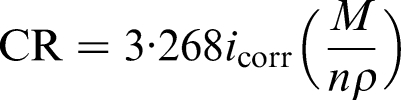
Based on the polarisation curves, the corrosion current density i corr can be obtained by Tafel extrapolation method, and then the CR was calculated using the Faraday law, iron density and i corr. All the recorded i corr values (expressed in mA cm−2) were converted into the CR in mm a(1 using the following expression
18
:
Results and discussion
Influence of H2S/CO2 partial pressure
Figure 2 shows the average CRs of L360QCS steel in corrosion environments containing different pressures of H2S/CO2. The results from Fig. 2 indicated that the CRs were very great compared to the criterion of average CRs (NACE RP0775-2005). According to the criterion, the steel was subjected to serious corrosion when the CR is higher than 0·125 mm a−1. The smallest CR in this study was approximately five times to the criterion value. Thus, L360QCS steel suffered serious corrosion in these corrosion environments. In addition, the CR decreased first and then increased with increasing H2S and CO2 partial pressure (p H2S and p CO2). In corrosion environment with 1·0 H2S and 0·67 CO2, the CR of L360QCS steel reached the minimum value.
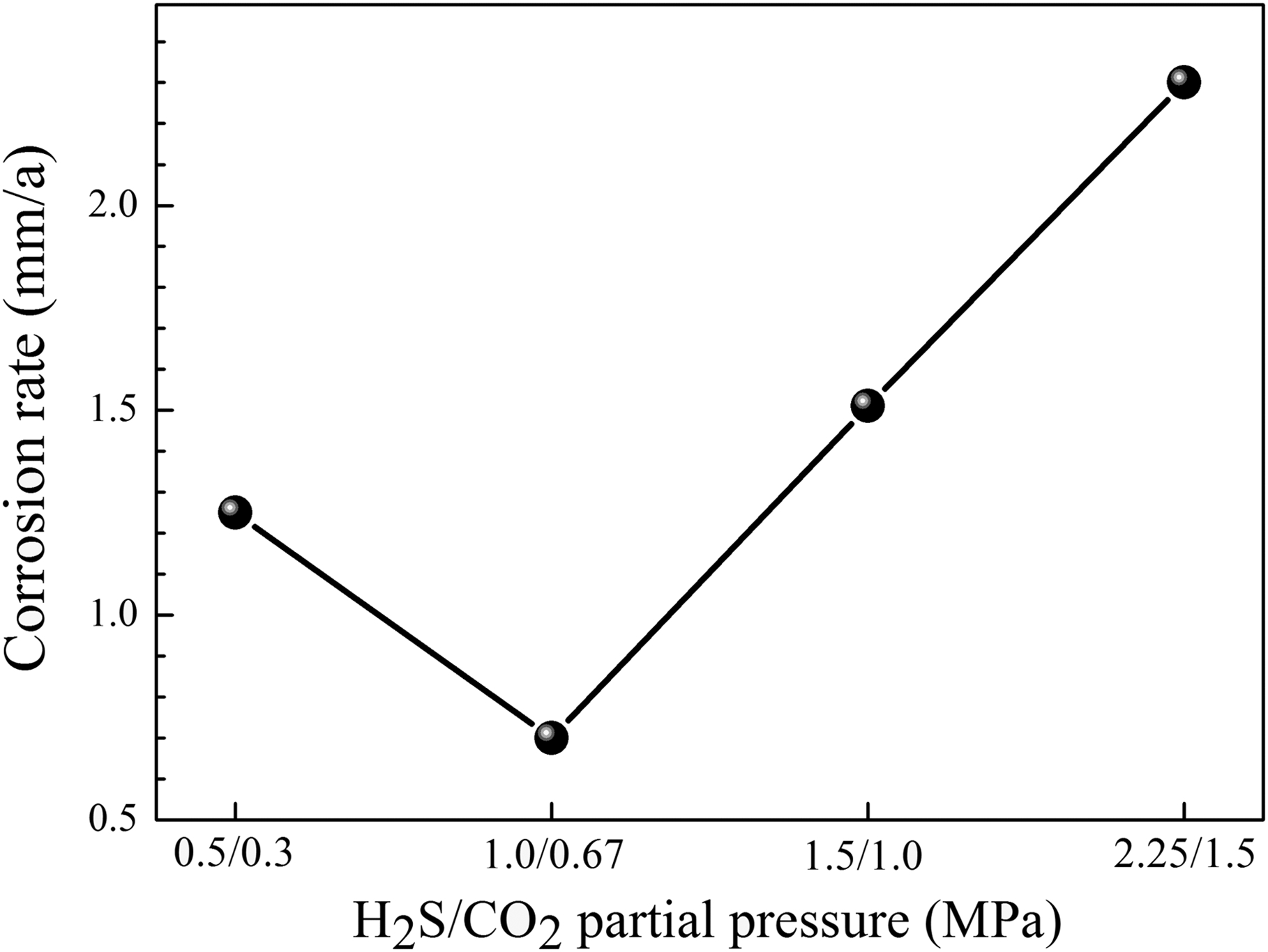
Average CRs of L360QCS steel in corrosion environments containing different pressures of H2S/CO2
Figure 3 shows the microcosmic morphologies of L360QCS steel surface in different corrosion environments. From Fig. 3a, it is seen that thick corrosion film existed on the steel surface in an environment with 0·5 MPa H2S and 0·3 MPa CO2. However, local corrosion film has fallen off from the steel surface. Furthermore, the corrosion film was uncontinuous and loose. Thus, the corrosion film that formed in the environment with 0·5 MPa H2S and 0·3 MPa CO2 possessed poor protection to the steel, resulting in high CR (Fig. 2). As for environment with 1·0 MPa H2S and 0·67 MPa CO2, the corrosion film was even and compact. Though some small local corrosion film fell off the steel surface, the corrosion film as a whole was closely attached to the steel surface, which could prevent steel from the corrosive medium. So the CR of L360QCS steel has a low value compared with that in environment with 0·5 MPa H2S and 0·3 MPa CO2 (Fig. 2). With further increase in p H2S and p CO2, the corrosion film was loose and the crystal grain was uneven (Fig. 3c and d), resulting in poor protection to the steel. Thus, the CRs increased with increasing p H2S and p CO2 (Fig. 2). Based on the above results, it is concluded that the CR is closely associated with the protectiveness of corrosion film.
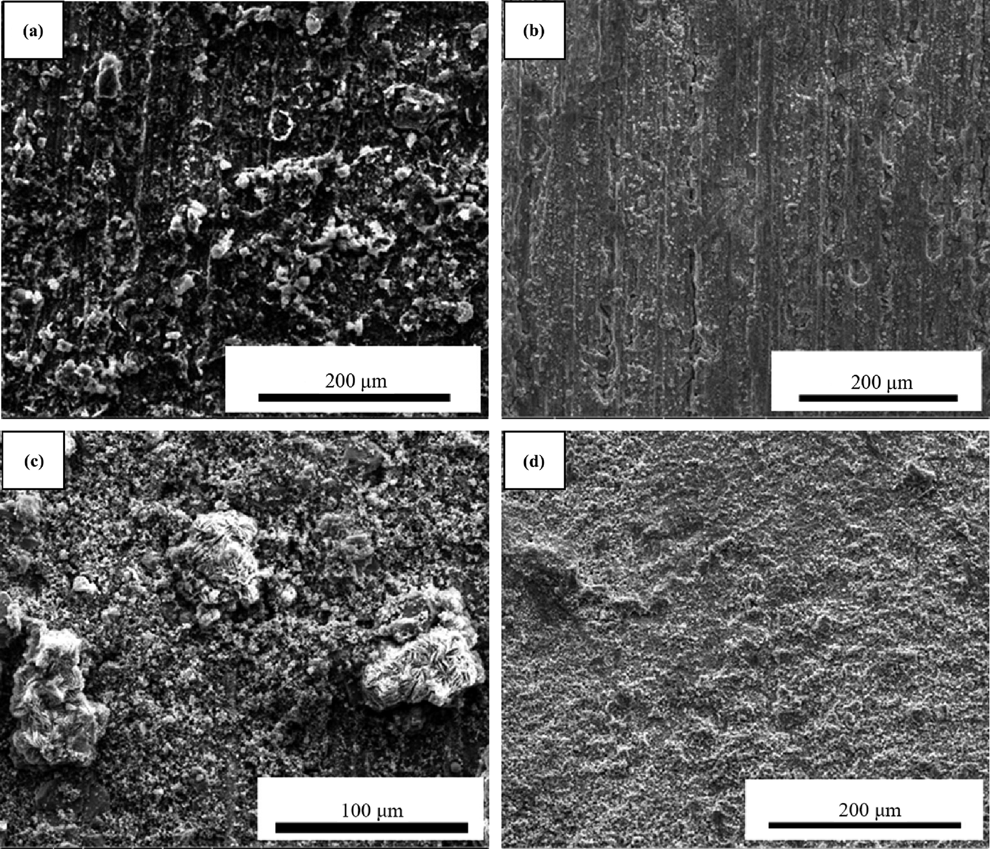
a 0.5 MPa H2S, 0.3 MPa CO2; b 1.0 MPa H2S, 0.67 MPa CO2; c 1.5 MPa H2S, 1.0 MPa CO2; d 2.25 MPa H2S, 1.5 MPa CO2Microcosmic morphologies of L360QCS steel surface in different corrosion environments
Influence of sulphur deposition
Figure 4 shows the CRs and macroscopic morphologies of L360QCS steel in corrosion environments in the absence and presence of sulphur deposition. As for the corrosion environments in the presence of sulphur deposition, the CR was ∼3·2 mm a(1 when no H2S and CO2 existed in the environments, which belongs to serious corrosion according to the criterion in NACE RP0775-2005. However, The CR increased significantly to 28·3 mm a−1 when small amounts of H2S and CO2 were added into the environments. From the macroscopic morphology of specimens, it can be seen that the specimens were subjected to very serious corrosion and has changed from regular rectangle shape to irregular one. The increasing degree of CR became very large with further increase in p H2S and p CO2 to 1·5 and 1·0 MPa, which could also be confirmed by the responding macroscopic morphology. Based on the aforementioned results, it can be recognised that H2S and CO2 play an important role in the steel corrosion in sulphur deposition environments. By comparing the 1·5 MPa H2S and 1·0 MPa CO2 environments with and without sulphur deposition, it can be seen that the influence of sulphur deposition on the CR of steel was enormous. The CR of L360QCS steel in the presence of sulphur deposition is ∼50 times than that in the absence of sulphur deposition. Thus, sulphur deposition is a critical influencing factor in the steel corrosion. In addition, it can be seen that the CR of L360QCS steel in H2S/CO2 environments with sulphur deposition was obviously large compared with that in single sulphur deposition or single H2S/CO2 environments. It can be concluded that the synergistic effect of sulphur deposition and H2S/CO2 gas could lead to very serious corrosion.
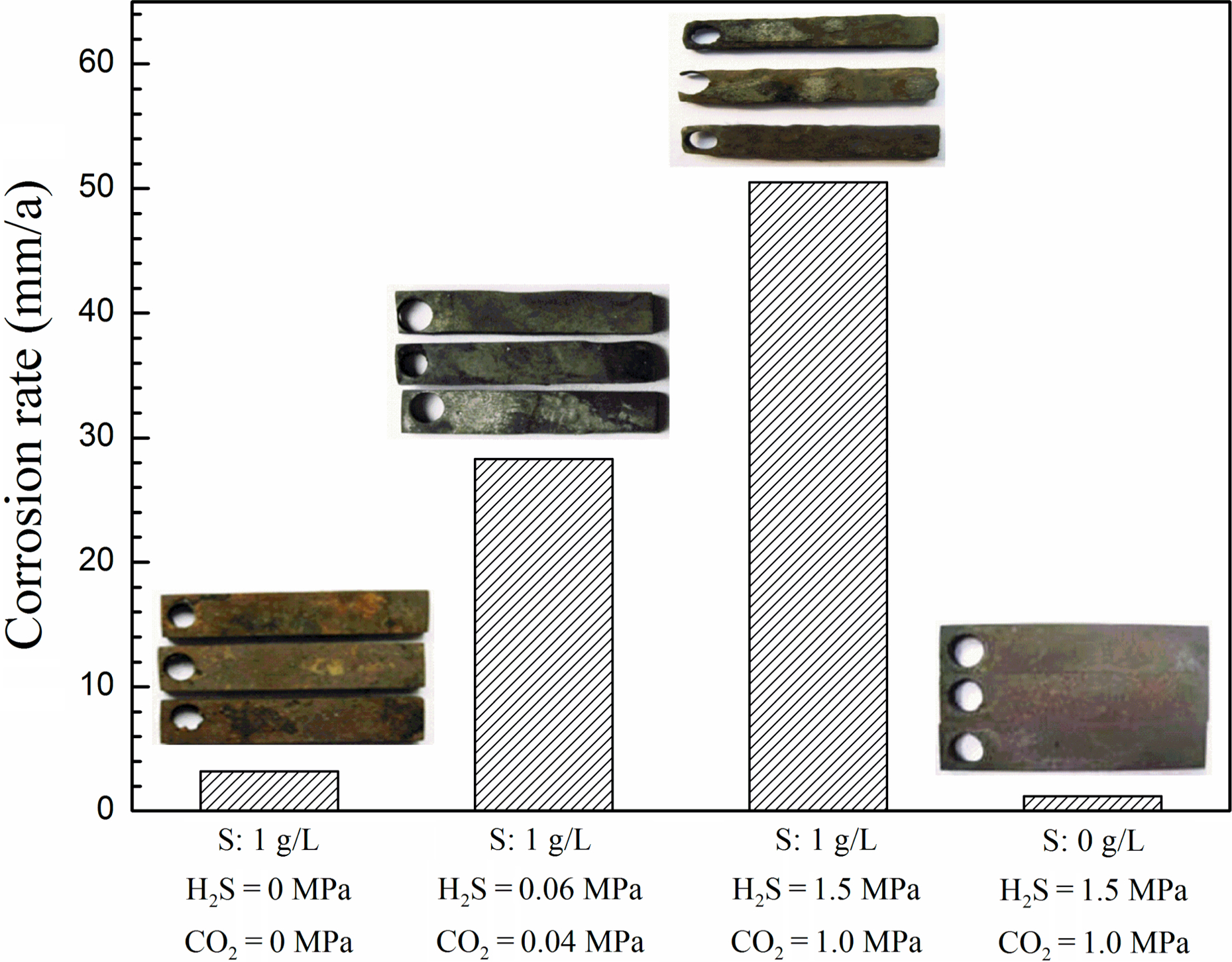
CRs and macroscopic morphologies of L360QCS steel in corrosion environments in absence and presence of sulphur deposition
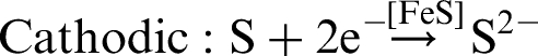
In sulphur deposition environments, accepted corrosion reactions are as follows
21
:


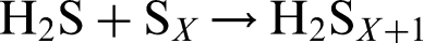
The accepted corrosion reactions of steel exposed to H2S/CO2 environments with sulphur deposition are as follows
22
:


Influence of corrosion inhibitor
Continuous corrosion inhibitor
Figure 5 shows the OCP of L360QCS steel after addition of different concentrations of continuous corrosion inhibitor. It can be seen that the OCP shifted toward the positive direction when continuous corrosion inhibitor was added into the solution. Furthermore, the OCP increased with an increase in the concentration of continuous corrosion inhibitor. The inhibition property is associated with the adsorption behaviour of the added inhibitor, which means that the inhibitor molecules could be absorbed on metal surface and form a barrier film. Thus, the direct interaction of corrosive media and metal surface was hindered. This result indicated that continuous corrosion inhibitor exhibited inhibiting effects to the corrosion of L360QCS steel, and the inhibiting effect could enhance increasing corrosion inhibitor concentration.
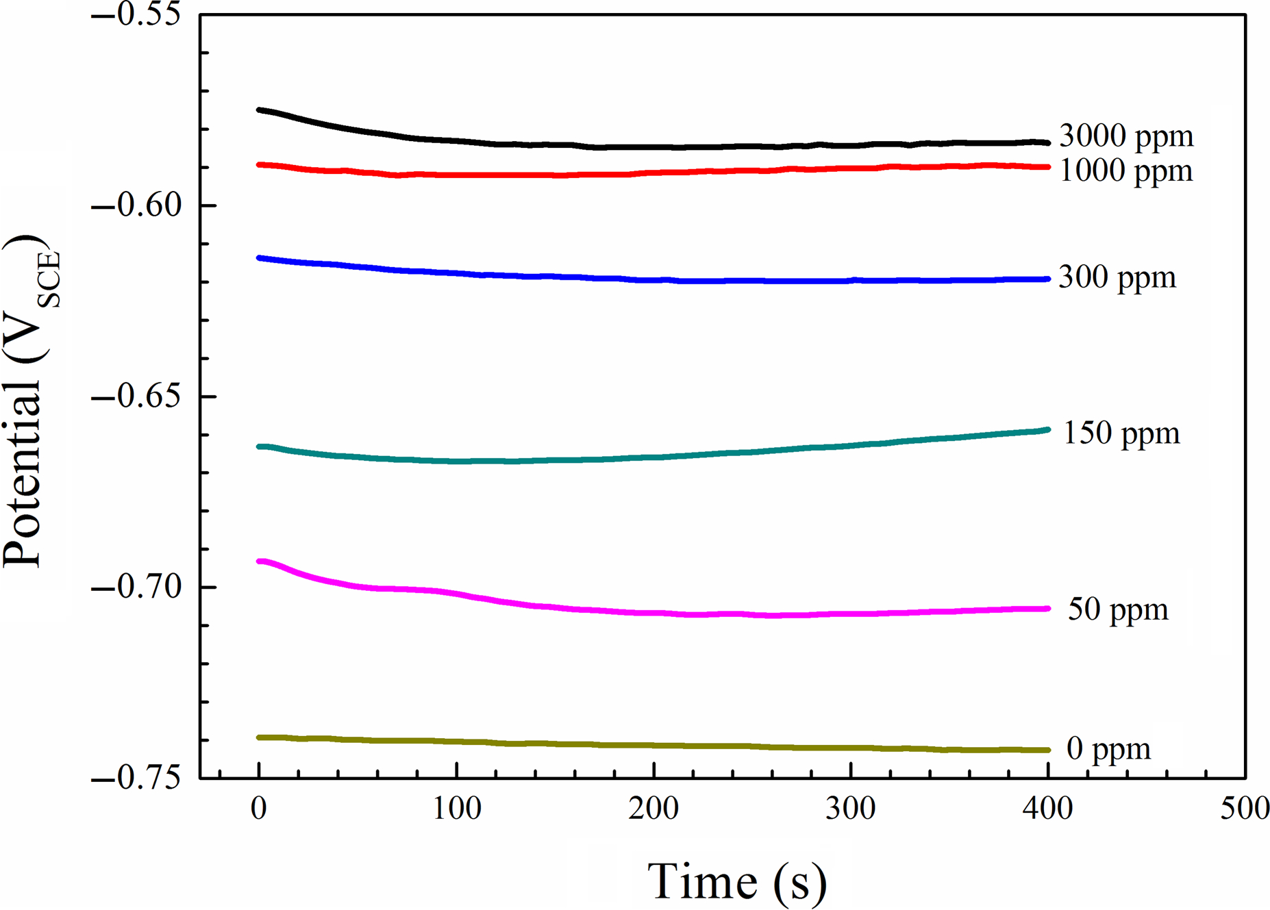
OCP of L360QCS steel after addition of different concentrations of continuous corrosion inhibitor
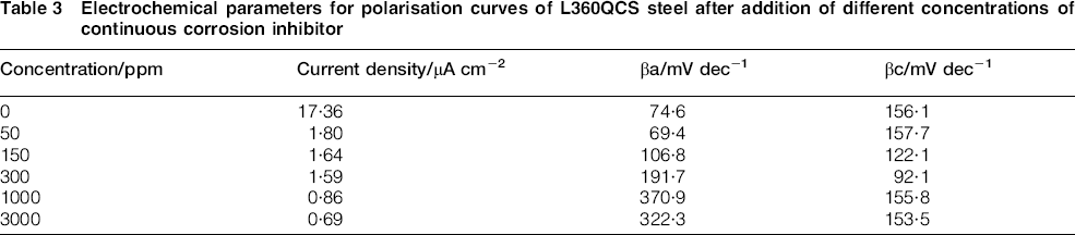
Figure 6 shows the polarisation curves of L360QCS steel after addition of different concentrations of continuous corrosion inhibitor. The corresponding electrochemical parameters for the polarisation curves of L360QCS steel after addition of different concentrations of continuous corrosion inhibitor was given in Table 3. It is seen that current density decreased obviously as the concentration of continuous corrosion inhibitor increased, which indicated that the inhibiting effect of corrosion inhibitor on corrosion was obvious. The anodic Tafel slope βa increased as the concentration of continuous corrosion inhibitor increased. It can be concluded that the inhibitor decreased the surface area for affecting the corrosion mechanism of steel, not only for corrosion. In addition, no significant change in the polarisation curves occurred as the concentration of corrosion inhibitor increased from 1000 to 3000 ppm. It is concluded that the inhibition effect of corrosion inhibitor has no obvious change with increasing concentration of corrosion inhibitor when the concentration is >1000 ppm. Based on the polarisation curves, the CR and η% were calculated and shown in Fig. 7. It can be seen that the increasing continuous corrosion inhibitor could lead to the decrease in CR and the increase in inhibition efficiency. However, the increasing degree of inhibition efficiency is inconspicuous when the corrosion inhibitor concentration increased from 1000 to 3000 ppm. The phenomenon demonstrated that the addition of continuous inhibitor would effectively protect metal surface from corrosion, while the additional concentration of concentration was 1000 ppm. The CR and η% of L360QCS steel in H2S/CO2 environments containing continuous corrosion inhibitor were also investigated by immersion tests. The corresponding results were given in Fig. 8. The results obtained by immersion tests were in accordance with the results gained using electrochemical measurement methods.
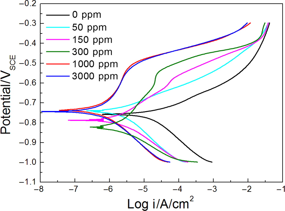
Polarisation curves of L360QCS steel after addition of different concentrations of continuous corrosion inhibitor
Electrochemical parameters for polarisation curves of L360QCS steel after addition of different concentrations of continuous corrosion inhibitor
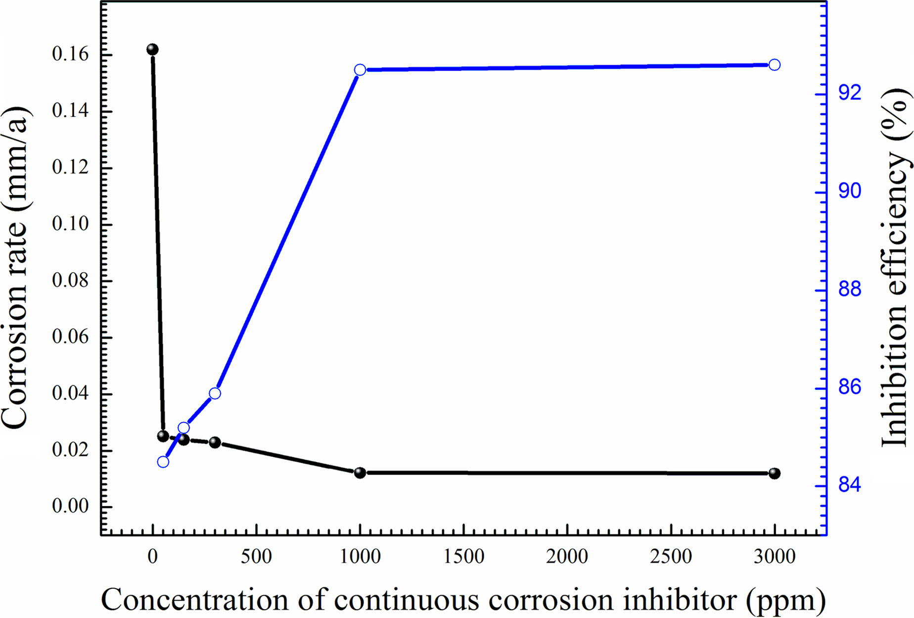
CR and inhibition efficiency of L360QCS steel after addition of different concentrations of continuous corrosion inhibitor
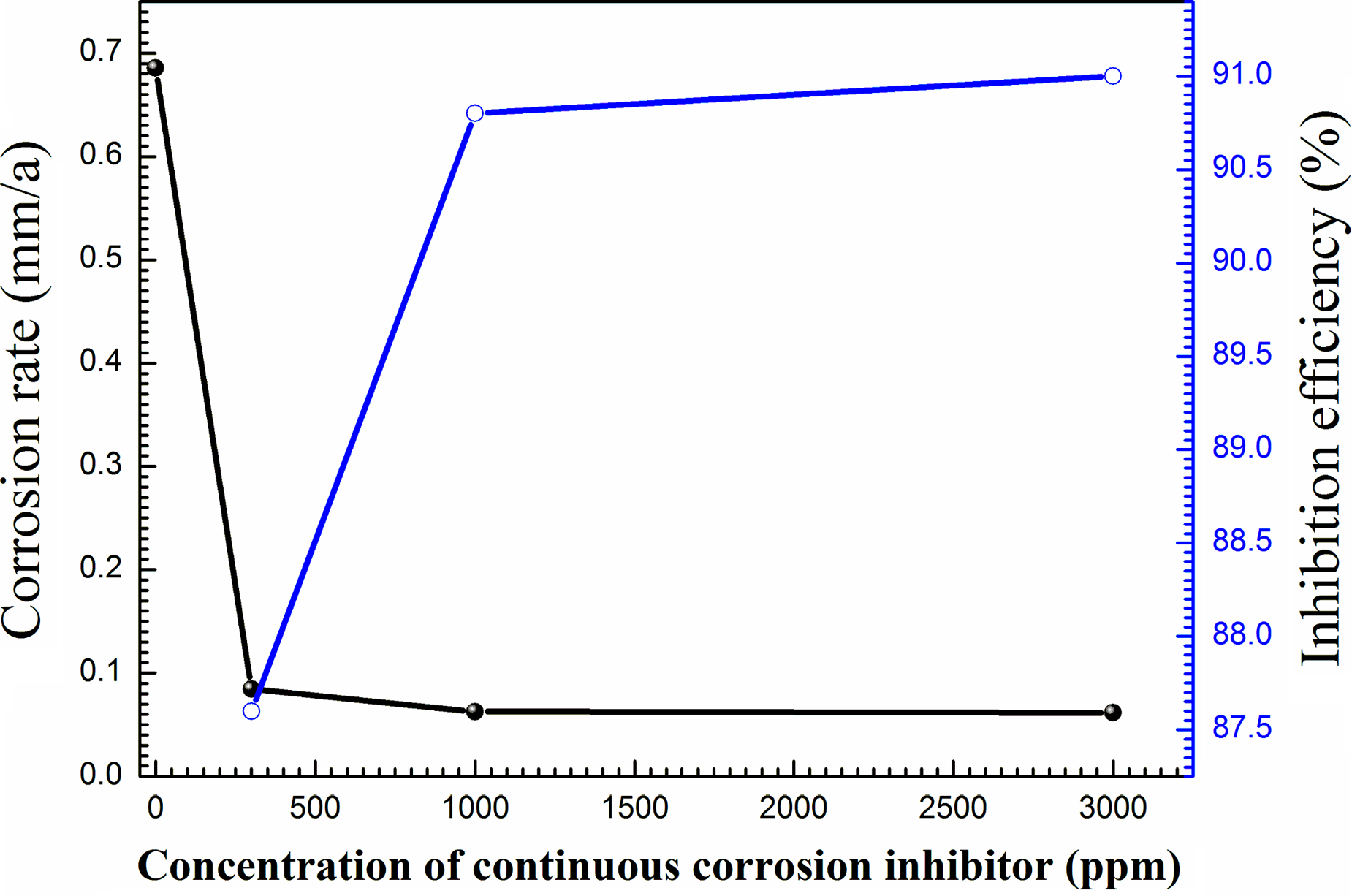
CR and inhibition efficiency of L360QCS steel in H2S/CO2 environment containing different concentrations of continuous corrosion inhibitor obtained by immersion tests
Prefilming corrosion inhibitor
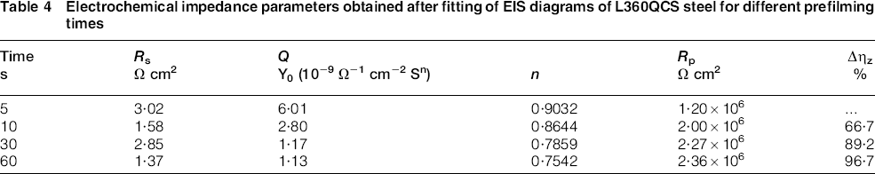
According to the results of section 3·3·1, the inhibition effect of continuous corrosion inhibitor was good when the concentration of corrosion inhibitor was 1000 and 3000 ppm. Furthermore, no significant change in the CR and inhibition efficiency occurred when corrosion inhibitor concentration increased from 1000 to 3000 ppm. Thus, 1000 ppm continuous corrosion inhibitor was better from the viewpoint of economic terms. To investigate the influence of prefilming corrosion inhibitor on the corrosion, 1000 ppm continuous corrosion inhibitor was selected in this section. First, the inhibition effect of prefilming inhibitor with time was investigated. Figure 9 shows the Nyquist diagrams of L360QCS steel for different prefilming time. As can be seen, the impedance response of steel changed after prefilming for different times. The EIS results can be interpreted in terms of the equivalent circuit of the electrical double layer shown in Fig. 10, which has been used previously to model the iron/acid interface. In this equivalent circuit, R s represents solution resistance, Q is the double layer capacitance between film and the solution and R p is the polarisation resistance. The EIS impedance parameters obtained after the fitting of EIS diagrams were shown in Table 4. It is found that that the polarisation resistance increased rapidly when the prefilm time increased from 5 to 10 s, and then the polarisation resistance increased slowly compared with the value in the first 10 s. The double layer capacitance decreased with the elapsing of time from 5 to 60 s. It is evidenced that the adsorption of inhibitors formed an adsorbed inhibitor film on the metal surface. The diffusion of the corrosive particles to the metal surface was hindered, resulting in increase in the polarisation resistance. Meanwhile, the double layer capacitance decreased with the increasing of time. The corresponding reason was that the deictic constant of the inhibitor molecule was smaller and the volume of the molecule was bigger compared with water molecules. To assess the inhibition efficiency of prefilming inhibitor with immersion time, the polarisation resistance was used to calculate the inhibition efficiency. The increasing inhibition efficiency Δηz% was used to assess clearly the variation of inhibition efficiency as immersion time increased. The polarisation resistance for 5 s of immersion time was selected as the reference. The corresponding results have been given in Table 4. It was found that the inhibition efficiency increased significantly as the immersion duration of specimens in the prefilming inhibition increased.
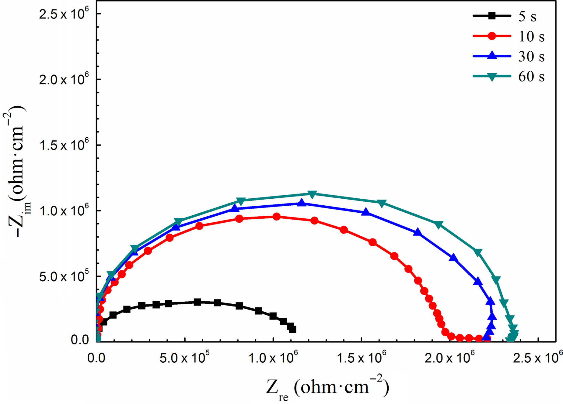
Nyquist diagrams of L360QCS steel for different prefilming times
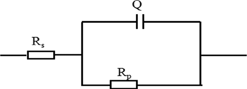
Electrochemical equivalent circuit for EIS fitting
Electrochemical impedance parameters obtained after fitting of EIS diagrams of L360QCS steel for different prefilming times
In addition, this work also studied the effect of sulphur deposition on the inhibition efficiency of steel after prefilming inhibitor immersion. The Nyquist diagrams of L360QCS steel in the absence and presence of sulphur deposition are shown in Fig. 11. Table 5 shows the EIS impedance parameters obtained after the fitting of EIS diagrams using the electrochemical equivalent circuit in Fig. 10. The polarisation resistance decreased significantly as soon as sulphur was added into the test solution, and the phenomenon indicated that sulphur could affect obviously the corrosion progress of L360QCS steel. The adsorption of inhibitor can protect metal surface from corrosion. The increasing inhibition efficiency Δηz% was used to assess clearly the variation of inhibition efficiency of steel in the absence and presence of sulphur deposition. The polarisation resistance with sulphur deposition was selected as the reference. The corresponding results have been given in Table 5. It was found that the inhibition efficiency increased significantly in the absence of sulphur deposition compared with that with sulphur deposition. It can be concluded that sulphur could lead to serious corrosion of steel in spite of the presence of prefilming.
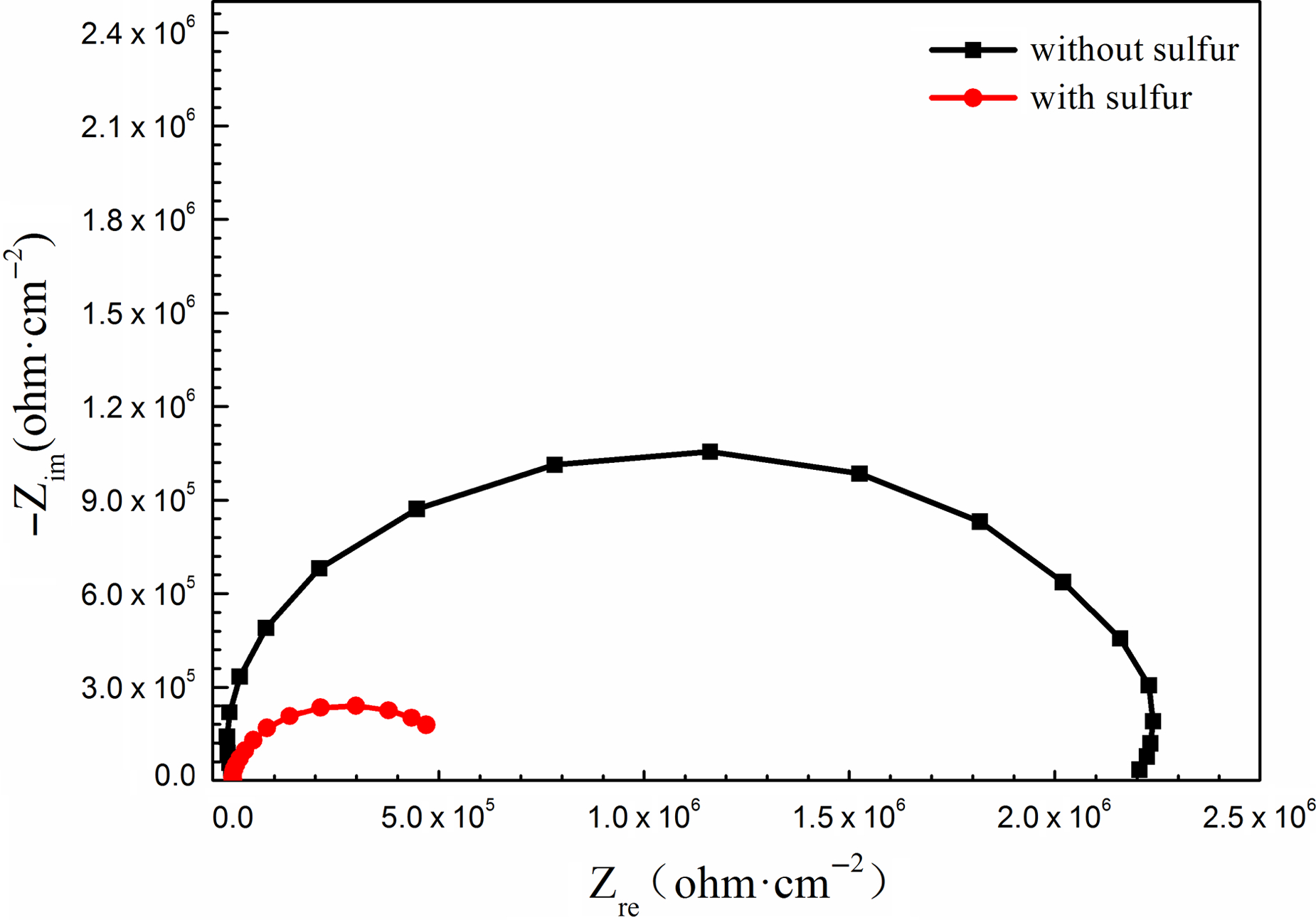
Nyquist diagrams of L360QCS steel in absence and presence of sulphur deposition
Electrochemical impedance parameters obtained after fitting of EIS diagrams of L360QCS steel in absence and presence of sulphur deposition
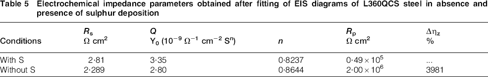
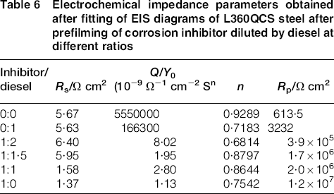
Figure 12 shows the OCP of L360QCS steel after prefilming of corrosion inhibitor diluted by diesel at different ratios. The OCP of specimens after prefilming increased obviously compared to no prefilming specimens. When specimens were prefilmed by pure corrosion inhibitor, the OCP was the highest. In addition, the OCP increased with decreasing proportion of diesel. This result showed that the corrosion tendency of L360QCS steel after prefilming of corrosion inhibitor became weak. In addition, it also can be seen that the OCP increased obviously when corrosion inhibitor/diesel ratio increased from 1:2 to 1:1·5. However, with further increase in corrosion inhibitor/diesel ratio from 1:1·5 to 1:1, the increasing amplitude of OCP was small. The results mentioned above indicated that the corrosion inhibitor/diesel ratio at 1:1·5 could be a better choice for the economic terms. To further investigate the influence of prefilming corrosion inhibitor, EIS was measured in this work. Figure 13 shows the Nyquist diagrams of L360QCS steel after prefilming of corrosion inhibitor diluted by diesel at different ratios. It is seen that Nyquist diagrams exhibited a depressed semicircle with a capacitive arc. Compared to the specimens without prefilming, the diameter of the capacitive semicircle of specimens after prefilming increased significantly. In addition, the diameter of the capacitive semicircle increased with decreasing proportion of diesel. This capacitive semicircle was associated with the resistance in the corrosion process.23–26 The equivalent circuit in Fig. 10 has been proposed for fitting EIS data to quantify the EIS electrochemical parameters (Table 6). It is seen that the polarisation resistance increased significantly after prefilming of corrosion inhibitor. Pure corrosion inhibitor prefilming could lead to the biggest polarisation resistance. In addition, the polarisation resistance increased with decreasing proportion of diesel. The high polarisation resistance could lead to high inhibition effect to corrosion process.
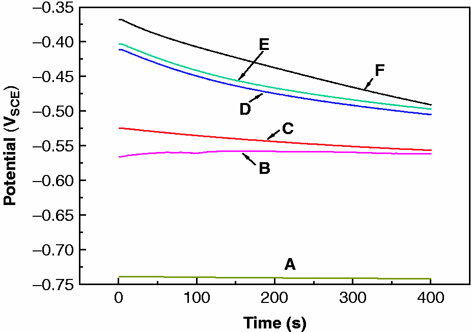
OCP of L360QCS steel after prefilming of corrosion inhibitor diluted by diesel at different ratios: a blank; b diesel; c corrosion inhibitor/diesel = 1:2; d corrosion inhibitor/diesel = 1:1.5; e corrosion inhibitor/diesel = 1:1; f pure prefilming corrosion inhibitor
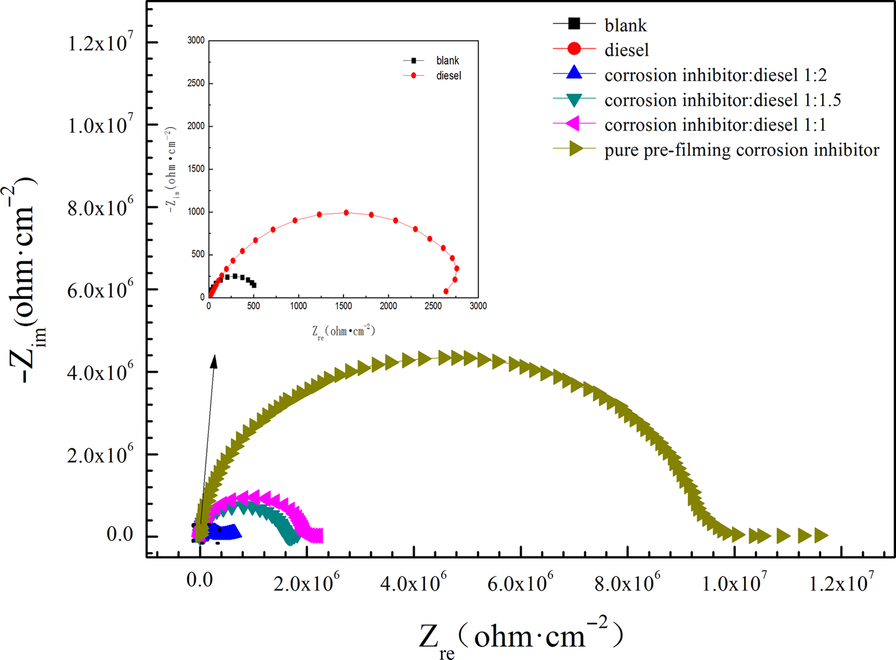
Nyquist diagrams of L360QCS steel after prefilming of corrosion inhibitor diluted by diesel at different ratios
Electrochemical impedance parameters obtained after fitting of EIS diagrams of L360QCS steel after prefilming of corrosion inhibitor diluted by diesel at different ratios
The effect of prefilming corrosion inhibitor on the corrosion behaviour of L360QCS steel in H2S/CO2 environments was also investigated by immersion tests. The CR and inhibition efficiency of L360QCS steel after prefilming with different ratios of corrosion inhibitor/diesel obtained by immersion tests were given in Fig. 14. It is seen that the CR of L360QCS steel decreased after prefilming with different corrosion inhibitor/diesel. In addition, the CR decreased with decreasing proportion of diesel. After prefilming, the η% of L360QCS steel increased. The results obtained by immersion tests were in accordance with the results gained using electrochemical measurement methods (Figs. 12 and 13).
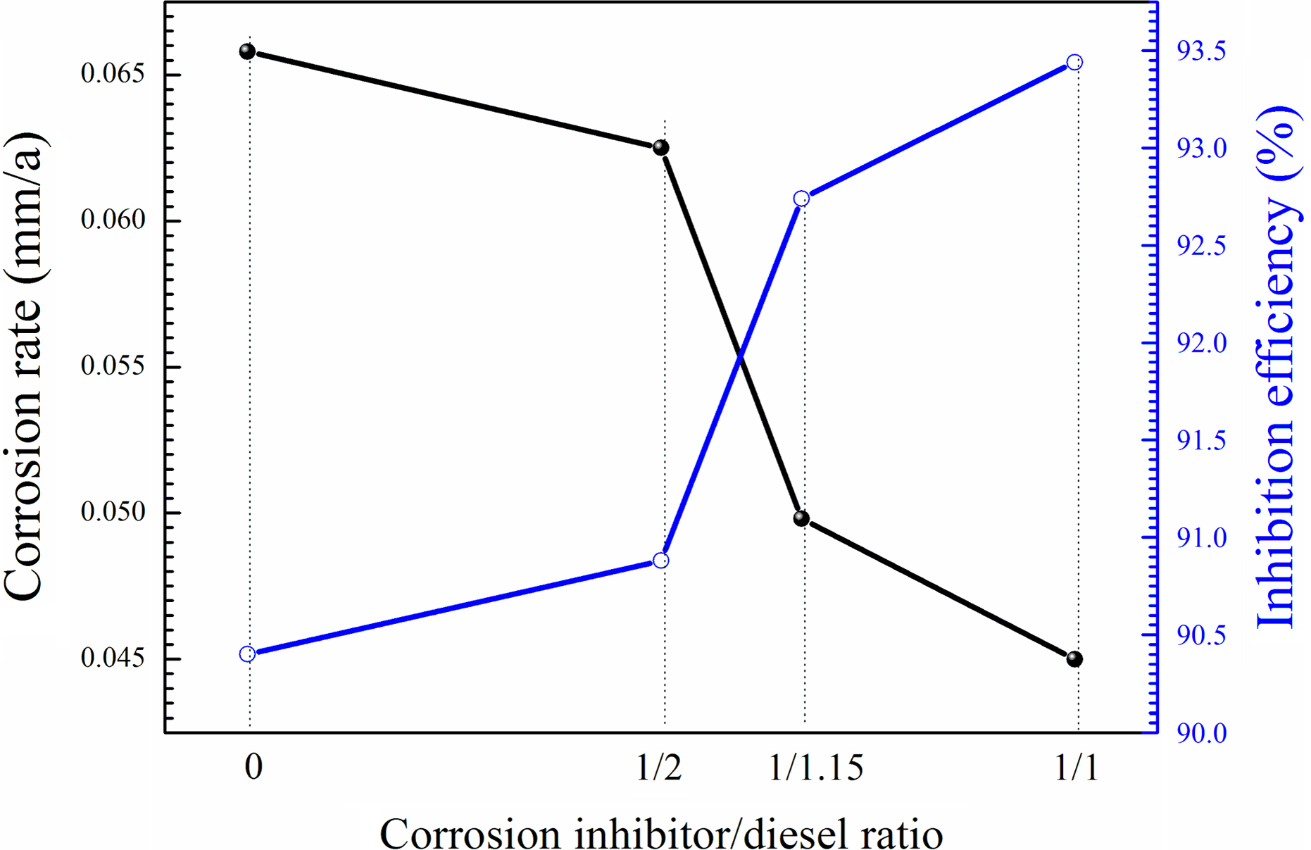
CR and inhibition efficiency of L360QCS steel after prefilming with different ratios of corrosion inhibitor/diesel obtained by immersion tests
Conclusions
In this study, the effect of H2S/CO2 partial pressure, sulphur deposition and corrosion inhibitor on the corrosion behaviour of L360QCS pipeline steel in H2S/CO2 environments was investigated. The following conclusions are drawn from the present work.
L360QCS steel would be subjected to serious corrosion in H2S/CO2 environments at 50°C. The CR of L360QCS steel decreased first and then increased with increasing p H2S and p CO2. CR is closely associated with the protectiveness of corrosion film. L360QCS steel in H2S/CO2 environments with sulphur deposition could suffer more serious corrosion than that in H2S/CO2 environments without sulphur deposition. Furthermore, the CR increased significantly with increasing p H2S and p CO2 in sulphur deposition environments. The synergistic effect of sulphur deposition and H2S/CO2 could be attributed to the serious corrosion of L360QCS steel. Continuous corrosion inhibitor exhibited effective inhibition effect to the corrosion, and the inhibition effect could enhance the increasing corrosion inhibitor concentration within a certain range. Compared to single continuous corrosion inhibitor, the CR of L360QCS steel after prefilming of corrosion inhibitor decreased obviously. Decreasing proportion of diesel could lead to the decrease in CR. In addition, the inhibition efficiency increased significantly with the increase in the prefilming time and the absence of sulphur deposition.
Acknowledgements
This work was supported by the National Natural Science Foundation of China (grant no. 51134011).