
Abstract
Corrosion can occur on underground pipelines especially at coating defects, where metal can be considered directly exposed to the soil, or under disbonded coatings, where the occluded geometry significantly affects the efficiency of cathodic protection (CP). In order to ensure the effectiveness of corrosion mitigation measures such as CP and protective coatings, inspection and monitoring of pipeline corrosion are required. This paper provides an overview of major methods that are used for inspecting and monitoring external corrosion of on-shore pipelines subjected to CP. Particular focus is on discussing the advantages and limitations of major inspection tools that are used to ensure pipeline integrity, and electrochemical corrosion sensors that are designed to monitor pipeline corrosion processes and rates. It is shown that there is a need for expanding the capabilities of corrosion monitoring methods suitable for the pipeline industry.
Introduction
Many energy pipelines are buried underground and are typically made of carbon steels such as X65 or X70. 1 Although these materials possess many favourable properties like low cost and suitable mechanical properties, they have an inherently low corrosion resistance in soil. To mitigate external corrosion, on-shore pipelines are typically protected by a combination of barrier coatings and impressed current cathodic protection (CP) systems. A detailed description of such CP systems can be found elsewhere.2,3 The objective of CP systems is to catholically polarise the pipeline, typically within the − 850 to − 1200 mVCSE potential range. More negative CP potentials may be required for mill scaled steel, when microbiologically induced corrosion (MIC) is suspected, in weak acid environments, or at high operating temperatures. On the other hand, less negative potentials could be acceptable for well-drained, well-aerated pipelines located in high resistivity soils or within concrete casings.4–6 Although it is widely accepted that corrosion rates at these CP potentials should decrease to acceptable levels, in practice, it is a great challenge to ensure that the complete structure is being properly polarised.
For instance, stray currents can locally affect the polarisation of a structure such as a buried pipeline. 7 These currents originate from sources external to the pipeline. The sources of stray currents can be diverse, from neighbouring pipelines 8 and electric trains,9,10 to natural sources such as telluric currents generated by changes in the earth magnetosphere.11,12 Since steel has a significantly lower electrical resistivity than soil, these currents tend to use the pipeline as a preferential conductive path. At the location where stray currents enter the pipeline, excessive cathodic polarisation is induced. This could, in extreme cases, produce an accelerated coating damage because of overprotection. However, the main concern lies where these currents exit the structure. At these locations, there is a local decrease in the cathodic polarisation and, in many cases, even anodic polarisation of the pipeline could be produced, leading to insufficient CP or even accelerated corrosion of the pipeline. 7
Another major cause of locally insufficient cathodic polarisation is the presence of disbonded coatings. Under a disbonded coating, a crevice is formed between the pipe and the disbonded coating where moisture and solution from the surrounding environment may enter. In the case of on-shore pipelines, it is believed that the high resistivity of the soil solution trapped within the crevice can shield CP currents, generating unprotected areas where corrosion might develop.13–15 Many forms of localised corrosion cases such as high16–20 and near-neutral16–18,21 pH stress corrosion cracking (SCC), pitting18,21,22 and MIC18,23–26 have been reported to be directly related to disbonded coatings. Although the mechanism by which disbonding takes place is still not fully understood, alkali reaction with the coating (saponification)27–29 and solubilisation of a pre-existent oxide film at the metal-coating interface 30 have been proposed as possible explanations. Other operational factors may also lead to temporary CP inefficacy. For example, failure of CP rectifiers or seasonal changes in the soil resistivity may cause localised insufficient CP.
In order to ensure the safe and cost-efficient operation of pipelines through the effective application of protective coatings and CP, corrosion must be constantly monitored and managed. Information obtained via corrosion inspection and monitoring activities enable pipeline owners to minimise failure risks by developing better maintenance strategies. The information obtained by these methods can also be used for predicting long-term remnant service life, and for providing warning of its possible failure.
Pipeline inspection techniques
These techniques are designed to assess the condition of a pipeline at a given point in time. These methods can provide compressive snapshots of the corrosion occurring along the pipeline; however, significant costs associated with their use limit their application frequency. These significant costs are often because of labour intensive tasks, the use of highly specialised equipment or losses from pipeline service interruptions. The following subsection discusses the most commonly applied inspection methods used in the pipeline industry in order of decreasing frequency of application.
Potential survey techniques
Electrical potential surveys are non-intrusive methods that are designed to indirectly evaluate the risk of pipeline corrosion. Although these methods do not measure corrosion rates or metal loss, they provide a way to locate coating defects and/or assess the effectiveness of the CP along the pipeline.
Close interval potential surveys (CIPS)
This group of potential survey methods involves the measurement of potential difference between a pipeline and a reference electrode in contact with the soil at regular distances (typically 1 m along the pipeline). A trailing cable is used to connect the reference electrode and a high impedance voltmeter to the nearest pipeline testing point (Fig. 1a). The survey objective is to evaluate if the pipeline is being polarised in accordance with the CP criteria. In addition, these surveys can help identify stray current pick up and discharge areas, medium to large coating defects and undesired electrical contact with other metallic structures. 31 To evaluate the infrared (IR) drop component of the measurements, GPS synchronised current interrupters are used to systematically switch on and off each of the CP rectifiers affecting the section under evaluation. Nevertheless, this method does not account for the IR drop produced by stray currents that are not interrupted during the CP-off survey. Therefore, stationary data loggers are also installed and synchronised. The data obtained is later used to compensate potential fluctuations produced by dynamic stray currents. 32 Typical surveys include measurement of the CP-on potential, Instantaneous CP-off potential and depolarisation of the pipeline to evaluate the fulfilment of the 100 mV of minimum polarisation required by many CP standards.4,33 A detailed explanation of the survey procedure can be found elsewhere.31,34,35
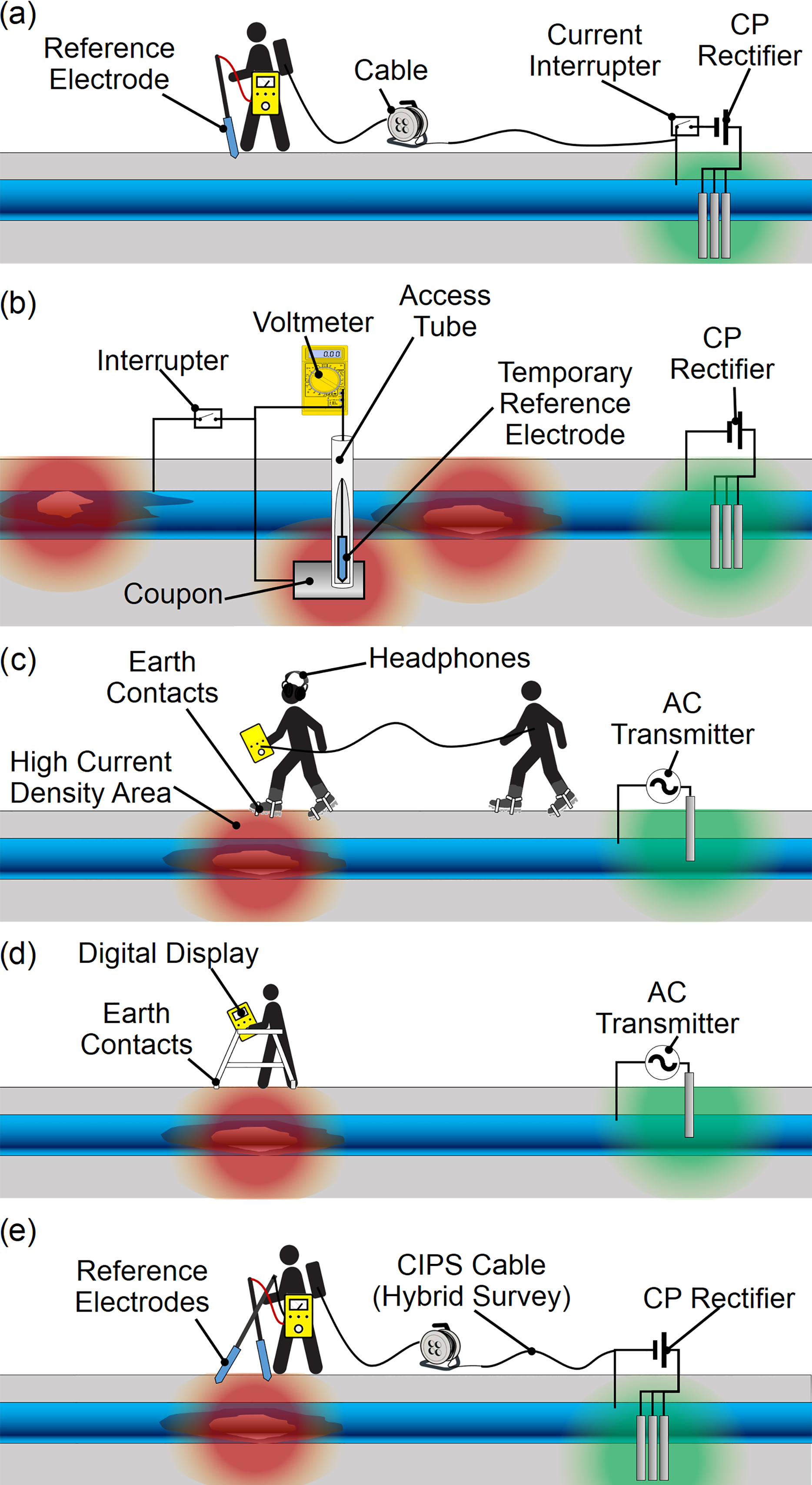
Potential survey methods. a Close interval potential surveys (CIPS), b infrared (IR) coupons, c Pearson, d modern alternating current voltage gradient (ACVG) and e direct current voltage gradient (DCVG)
IR coupons
Steel coupons buried next to the pipe and electrically connected to it are also used to assess the operation of a CP system. Although these coupons can only provide information regarding the polarisation achieved at discrete locations, they offer a more effective way to minimise IR drops (including those produced by stray currents). Accurate IR drop free potential measurements between the coupons and a reference electrode placed next to the coupon can be obtained by interrupting the electrical link between the coupon and the pipeline (Fig. 1b). 4 They have been used in Europe 3 and North America36,37 since the 70s with very positive results.
Alternating current voltage gradient (ACVG) methods
These methods consist in applying an AC signal to the pipeline by means of a transmitter unit. At coating failure areas, where the steel is in direct contact with the soil, this AC signal would leak from the pipe generating a zone of high current density. This high current density would in turn produce a potential gradient in the highly resistive soil. During the survey, the changes in potential difference between two earth contacts maintained a constant distance apart are measured and used to pinpoint coating defects. The Pearson survey (Fig. 1c) is based on this principle and developed in the 1940s was the first technique capable of locating coating holidays at pipelines. For this survey, the impressed AC signal lays in the audible frequency range (typically 1000 Hz). During the survey, the potential gradient is measured between two operators that walk along the pipeline typically 7 m apart from each other using metal cleats attached to their boots (earth contacts). The receiver unit carried by one of the operators converts the potential difference into an audio signal for identification of defective areas. Although this method has been replaced mostly by other survey methods, it is still used on recently installed pipelines without permanent CP units and in areas of significant stray currents. Recent implementations of alternating current voltage gradient (ACVG) removed the need for a second operator using ski poles or an A-shaped frame to support both earth contacts (typically 1 m apart) (Fig. 1d). Also, the audio output has been replaced by a digital display with arrows pinpointing the defective locations with additional data logging capabilities. More details on these methods can be found elsewhere. 38
Direct current voltage gradient (DCVG) method
This is another potential survey method that aims to locate defects in the pipeline coating. Unlike the Pearson survey, this method does not require a transmitter unit; it uses the impressed current by the CP units. In order to locate coating defects, voltage gradients are measured by a single operator using two reference electrodes in contact with the soil at a constant distance (typically 1 m) (Fig. 1e).39,40 Direct current voltage gradient (DCVG) has some interesting advantages over the Pearson survey that gradually lead to its establishment as the preferred method for the detection of coating holidays. For example, the labour involved during the survey is significantly reduced since a single operator can perform it and no transmitter unit needs to be installed and frequently repositioned during the survey. In addition, the similarity of the equipment allows this survey to be combined with close interval potential survey (CIPS) into what are called hybrid surveys.
While both DCVG and the Pearson method are very effective tools to locate coating defects, no general relation between the potentials measured and the defect size can be determined. The IR drop measured at each area is affected by many other factors beside the defect size. Another important limitation of these surveys is that they cannot indicate the presence of disbonded coatings. This is because disbonded coatings shield the CP current and therefore no potential gradient is produced in soil surrounding the pipeline. Nevertheless, it has been reported that the relative comparison of the DCVG values obtained under similar conditions for the same pipeline could prove useful in establishing a priority order for maintenance. 39
Inline inspection (ILI) tools
Inline inspection (ILI) tools (also known as smart pigs) are cylindrical non-destructive testing (NDT) tools that are inserted in the pipe to inspect it while being carried by the fluid flow. There is a wide variety of ILI tools that specialises in the detection of metal loss, cracks, geometry deformations, leaks, and wax deposition.41,42 This review only discusses those ILI technologies capable of evaluating external corrosion defects.
Magnetic flux leakages (MFL)
This technology illustrated in Fig. 2 uses very strong magnets to saturate a section of the pipe, and to ensure that any metal loss produces a change in magnetic flux leakage (MFL). Two sets of metallic brushes are used to ensure a close contact between each pole of the permanent magnets and the pipe. Hall effect sensors placed in the saturated area are used to measure any variation in the strength of the magnetic field. To discriminate internal from external defects, a second set of sensors may be used outside of the saturated area, where only remnant magnetisation is affecting the pipe and leakages could only be attributed to internal defects. 43 Alternatively, another NDT technology such as eddy currents could be used for this task. 44 The detection capabilities of MFL depend on the orientation of the defect with respect to the magnetic flux, with maximum detection of defects oriented perpendicular to the magnetic flux. 45 Most MFL tools aim to detect metal loss and orientate the magnetic flux parallel to the pipeline axis. Tools producing circumferential or spiral magnetisations have also been developed for crack detection. 41 Unfortunately, when the magnetisation direction is not parallel to the pipeline, the displacement of the magnetic field as the tool advances induces electrical currents on the pipe that can significantly affect the measurements. 45 In all cases, MFL tools only measure magnetic flux anomalies. Given that there is no deterministic relation between magnetic flux changes and metal loss, estimations of defect size and quantification rely on statistical assumptions.45,46
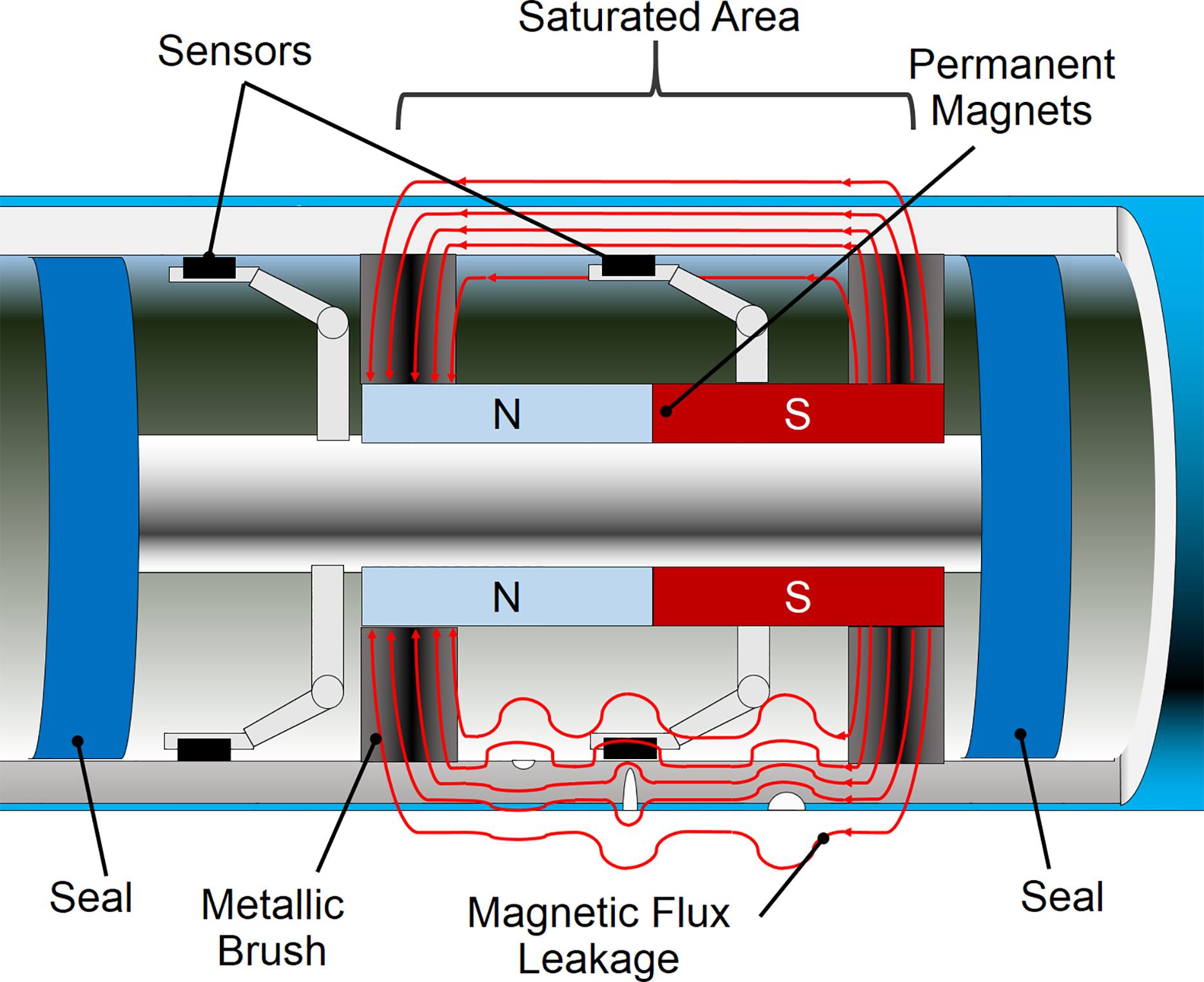
Longitudinal cross-section of a magnetic flux leakages (MFL) inline inspection (ILI)-tool
Ultrasonic transducers (UT)
These tools (Fig. 3) use piezoelectric transducers to generate ultrasonic pulses. The time between the reflection of the signal produced at each interface is used to calculate internal as well as external metal losses. 42 Although these tools were originally designed for metal loss detection, design variations that arrange the transducers at an angle respect to the pipe's internal wall were developed for crack detection applications.41,47 In general, ultrasonic transducers (UT) tools have better detection capabilities than MFL tools and produce signals that can be directly related to defects sizes and quantity. 48 Nevertheless this technology has a critical drawback, it needs a homogenous liquid coupling agent between the transducers and the pipe, which seriously limits its application on gas pipelines. 41 In order to overcome this limitation, a train of pigs can be used to isolate and carry a batch of liquid together with the conventional UT tool (Fig. 3).41,49 As an alternative option, a coupling agent-free UT tool known as ‘elastic wave’ was specifically developed for gas pipelines in which the UT are allocated inside elastic wheels. These wheels have similar acoustic impedance to the pipeline and deform elastically leaving no gas pockets at the wheel/pipe wall interface, ensuring adequate acoustic coupling. 49
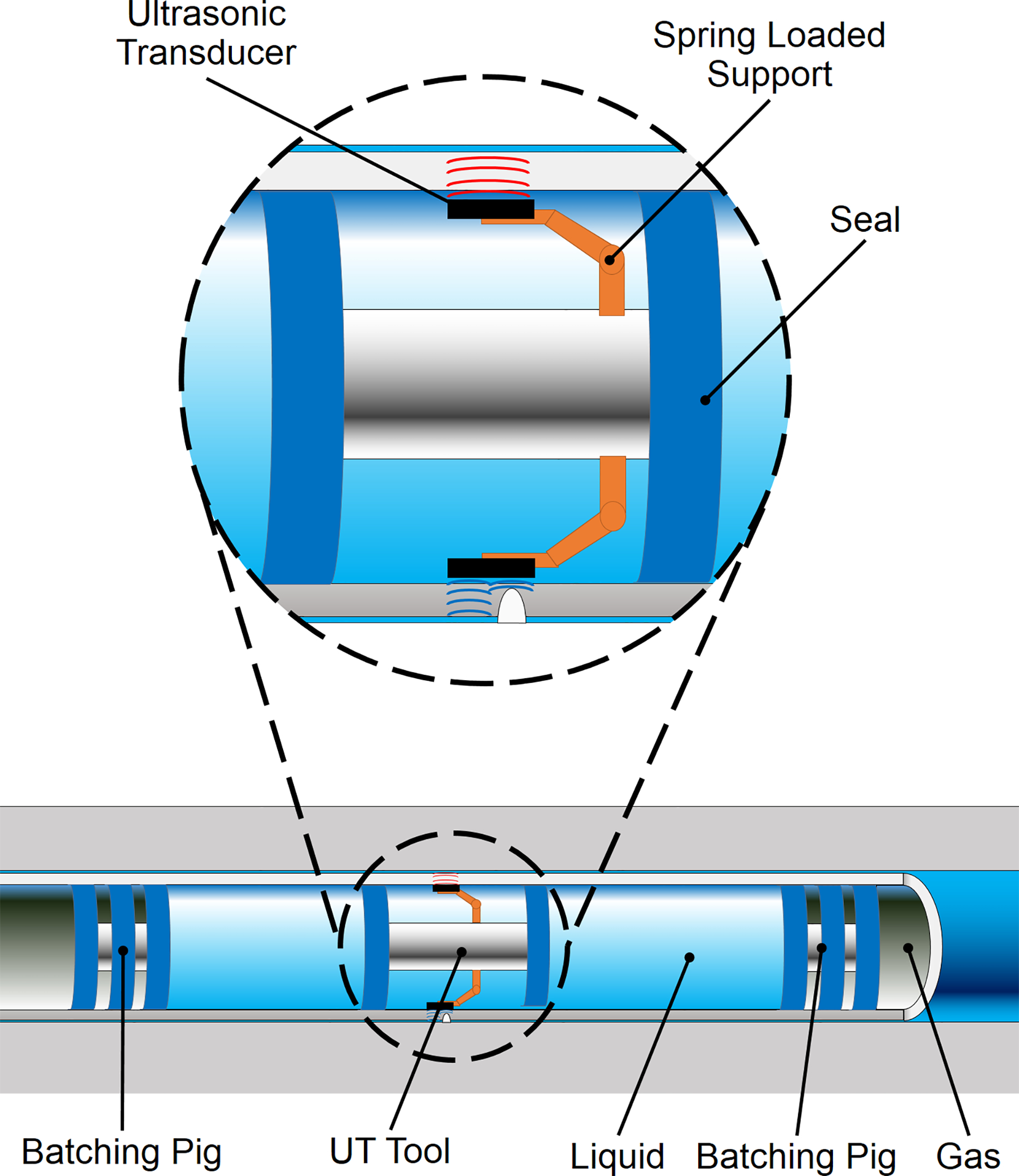
Longitudinal cross-section of a ultrasonic transducers (UT) inline inspection (ILI)-tool and batching method for gas pipelines
Electromagnetic acoustic transducers (EMAT)
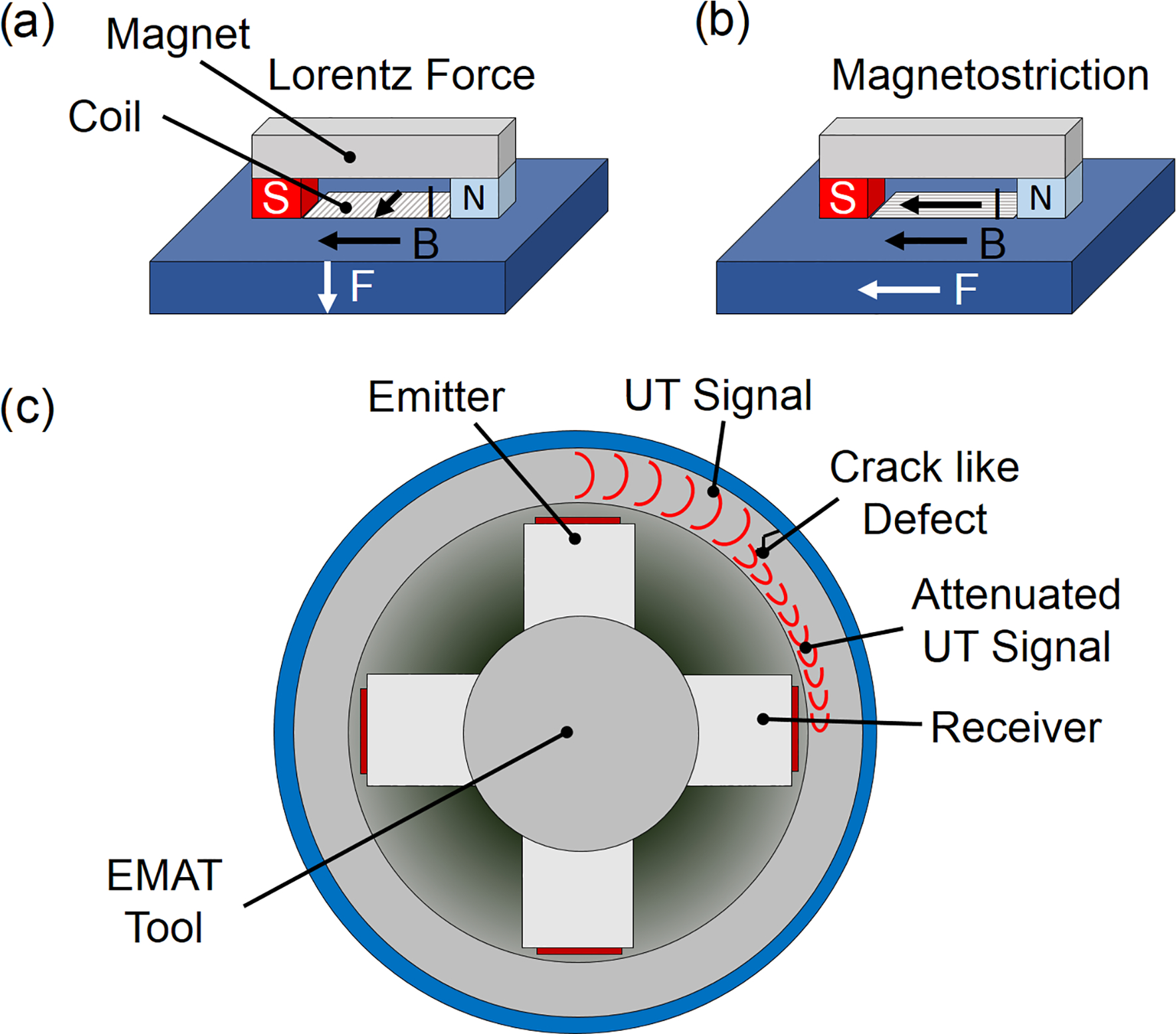
Electromagnetic acoustic transducer (EMAT) is a recently developed technology that generates and receives ultrasonic waves without requiring a liquid coupling agent. Electromagnetic acoustic transducer achieves this by means of the Lorenz Force50,51 (Fig. 4a) and magnetostriction (Fig. 4b).52,53 Each transducer consists of a permanent magnet and a flat electrical coil. The ultrasonic wave is produced directly on the pipe wall when a burst high frequency signal is feed to the coil. The wave mode generated in the steel can be tailored by using specific arrangements of permanent magnets and different coils designs. Although its detection capabilities are not as good as UT, EMAT is widely accepted as a crack and coating disbondment detection tool for gas pipelines, where its couplant-free characteristic is fully utilised (Fig. 4c).54–57
Electromagnetic acoustic transducer (EMAT) technology a Ultrasonic transducers (UT) wave generated by Lorentz Force, b UT wave generated by magnetostriction and c transverse cross-section of a EMAT inline inspection (ILI)-tool
Eddy currents
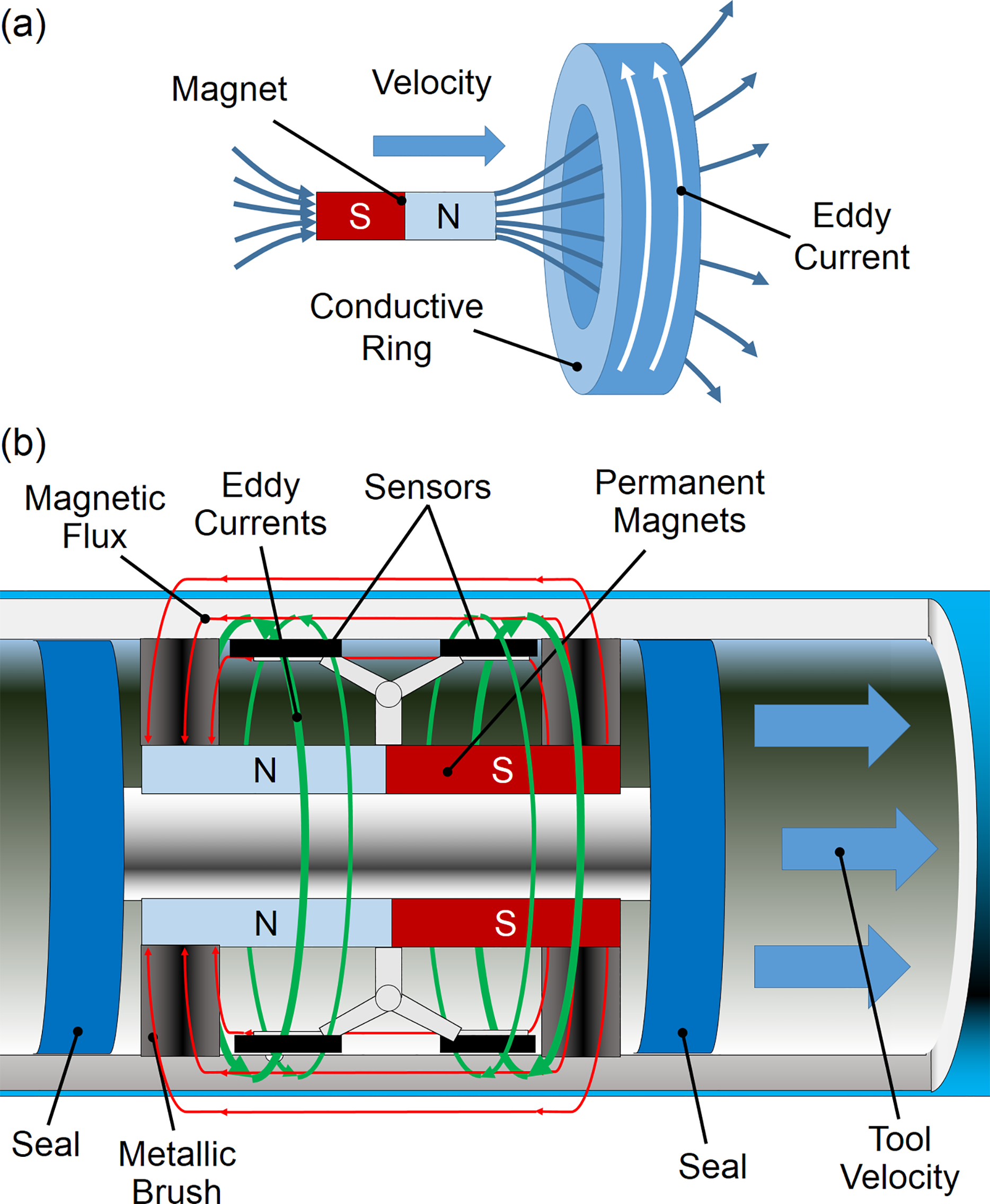
This tool takes advantage of Faraday's Law of induction, which states that when a conductor is placed in presence of a variable magnetic flux, an eddy current is induced in it (Fig. 5a). In traditional eddy currents, tools coils supplied with an alternating current are used to induce an opposing alternating current on the inspected material. This technology has been used in ILI tools for pipelines only for the detection of internal anomalies because of the limited penetration of the signal through the pipe wall. 41 However, a new tool capable of detecting cracks based on self-excited eddy currents has been recently presented. 58 This tool is similar to a traditional MFL tools both physically and operationally (Fig. 5b). As the tool travels through the pipe at high speeds (above 3 m s−1), the rapid magnetisation of the pipe produced by the tools permanent magnets, generates circumferential eddy currents across the pipewall. If longitudinal cracks are present, these eddy currents are disturbed producing a change in the magnetic field that is perceived by the tool's sensors.
Self-exited eddy currents a Graphical representation of Faraday's law of induction and b self-exited eddy currents inline inspection (ILI) tool
Tools for inspecting non-piggable pipelines
The use of ILI tools should be a requirement incorporated at the design stage of the pipeline.41,49 Modern pipelines have taken these design requirements into consideration; however, a large number of pipelines currently in service were constructed before the introduction of ILI tools and are currently considered non-piggable. 59 Retrofitting these pipelines can be very expensive and disruptive. 49 Therefore, alternative methods for inspection had been developed to ensure pipeline fitness for service.
Pipeline crawlers
These are non-autonomous, self-propelled specially designed ILI tools capable of inspecting pipes with non-circular valves and tight bends. In many cases, these tools are also capable of moving against the fluid flow. Ultrasonics is the most common external corrosion detection technology used with this type of tool. 49
Guided-wave ultrasonics
This method requires digging up the pipeline at discrete location to mount a ring of UT around the circumference of the pipe (Fig. 6). These transducers are used to send ultrasonic waves along the pipe and receive the echo signals produced by welds and corrosion defects.60,61 This technique can only inspect over short distances and produces signals requiring complex interpretation, which do not differentiate between internal and external defects. 62 Nevertheless, the guided waves method has proven to be a valuable tool for non-piggable pipeline sections such as at road crossings where digging up could be significantly more expensive.49,63
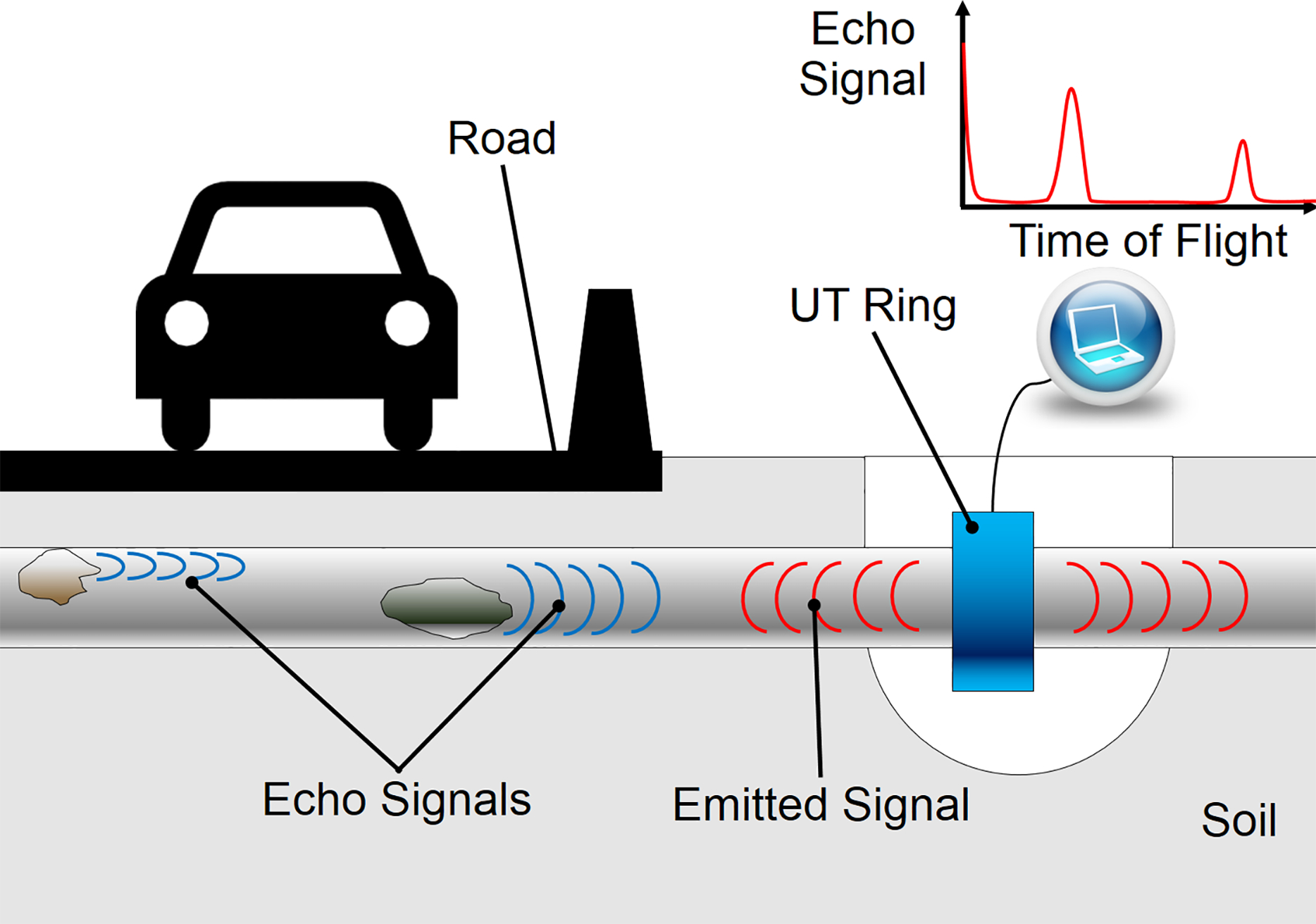
Guided-wave ultrasonics
External corrosion direct assessment (ECDA)
This is a risk-based assessment method that integrates all relevant data available, in order to identify the most corrosion susceptible areas along the pipeline. Although external corrosion direct assessment (ECDA) is applicable to any pipeline, the method is of particular value for non-piggable pipelines providing rational selection criteria for dig up programmes. The information sources include historical design, construction and maintenance data, CP performance and coating surveys, soil conductivity, moisture and composition data, and ILI inspection results (if available). 49 Based on this information, a probabilistic model is used to calculate the highest corrosion risk locations. These locations are then excavated, carefully examined using tools, such as UT probes and 3D scanners and if necessary, repaired. Finally, the data collected from the direct inspection activities are feedback to validate the adopted probabilistic model.18,59 A detailed description of the method can be found elsewhere.64,65
Hydrostatic tests
Hydrostatic testing consists of isolating sections of the pipeline, pressurising them above the maximum allowable operating pressure using incompressible fluids (typically water) and monitoring any pressure drop attributable to leaks. A detailed description of the procedure can be found elsewhere. 66 Although this test is important to assure pipeline fitness for service, it provides no information regarding the presence of subcritical defects. In addition, it involves large operational costs and long downtimes. 59 Therefore, for existing pipelines, it is only used as a measure of last resort. 49
Corrosion monitoring
Unlike inspection, corrosion monitoring does not aim to ascertain if a pipeline is fit for service by assessing the existing damage produced by corrosion. Instead, it aims to identify if corrosion is currently taking place and the rates and pattern of corrosion. This methodology has been under active development for the last 30 years and is generally based on the use of specially designed probes that simulate the conditions occurring on the pipeline surface and measure corrosion rates and patterns. Most of these probes were initially designed for application in other industrial environments. They were later modified to suit the pipeline industry. Although many techniques are currently available to measure corrosion rates in relatively short times, only a few of them are compatible with CP systems. In the following subsections, the most relevant techniques will be reviewed.
Non-electrochemical methods
These methods are relatively easy to operate; however, they have low measurement sensitivity, because they do not measure corrosion rates directly, instead they compare metal losses at different times or monitor corrosion indirectly by measuring other variables such as changes in physical properties.
Corrosion coupons
The relative success of coupons to monitor IR drop free CP potentials has already been discussed above in the IR coupons section. In this section, the authors focus on the use of coupons to measure corrosion rates and patterns. This is one of the most widely applied techniques to obtain corrosion information about a system. These coupons work under the assumption that when exposed to the same environmental and CP conditions as the pipeline, the corrosion process will affect both surfaces in a similar way. The exposed surface of the metal coupon can be completely coated, coated but with pre-existent defect or left bare, representing different features of the pipeline surface. After being exposed to a corrosion environment for a period of time and recovered, information regarding general as well as localised corrosion can be obtained by visual, microscopic and weight-loss analysis of the coupon. Also, preloaded coupons can be used to obtain information regarding SCC. The main limitation of this technique is that only average corrosion rates can be obtained once the coupons are recovered. This is essentially the same information obtained by careful examination of the pipeline surface during dig up operations. In addition, the costs associated with their underground installation and recovery can be significant. Consequently, coupons are not generally used as a corrosion rate monitoring tool within the pipeline industry, but as method to evaluate IR drop free potentials.
Electrical resistance (ER) probes
These probes monitor the electrical resistance (ER) between ends of an elongated ‘coupon’ of constant cross-section installed in the corrosive environment. As the coupon is corroded, its cross-section is reduced and consequently, its ER increases. Since material conductivity changes with temperature, most probes also include a temperature compensation device. Since this method is based on the detection of metal loss, the coupon can be electrically connected to the pipeline to simulate the bare metal exposed in a coating defect and disconnected for measurement, providing representative values under CP.67,68 In addition, this method is independent of the medium resistivity, which promotes its application in many complex environments where electrochemical methods have difficulties. High sensitivity probes capable of measuring corrosion rates of a few micrometre per year in a few hours were recently developed. These probes utilised thin layers of metal deposited by vapour deposition.67,69 Unfortunately, reduction of the coupon's cross-section also reduced the probe's service life. 18 The main disadvantages of ER probes are their low sensitivity, and that accurate results can only be achieved if the corrosion is uniformly distributed over the sensor surface. In the case of underground bare steels under CP, this is often not the case because of the localised forms of attack promoted by steel passivation at high pH. In an attempt to deal with this problem, thin multifilament sensors were developed in recent years by Li et. al. 69
Inductance probes
This type of probes evaluates metal loss on a coupon exposed to the environment using the same principles as eddy currents. Although these probes are less sensible to temperature changes and generally more sensitive than ER probes, they share similar limitations regarding quantification of localised corrosion from generalised metal loss.
Fibre optic sensors
The use of optical fibres to indirectly monitor corrosion issues in pipelines by taking advantage of the influence of temperature and strain levels on their optical properties has been proposed. 70 This method requires that one or more optical fibres be placed in close proximity to the pipeline in order to sense local temperature and strain gradients produced by changes in pipeline wall thickness. Although this measuring principle would be capable only of detecting advanced corrosion, a single fibre could monitor more than 100 km of pipeline. 71 The main disadvantage of these sensors besides their low sensitivity is that it requires delicate installation of fragile fibres in close proximity to the pipeline wall. Another drawback is that corrosion is being evaluated indirectly. This implies the need for certain assumptions that could not always be valid (e.g. that temperature and stain changes are only because of corrosion, not because of other factors such as earth movement, etc.).
Electrochemical methods
Corrosion in aqueous environments is an electrochemical process and, by assuming that the process follows Faraday's law, many corrosion probes are generally capable of providing information regarding instantaneous corrosion rates in almost continuous basis. However, the presence of CP, a highly resistive soil environment and coated surfaces makes the accurate electrochemical measurements extremely challenging. This may explain the fact that although electrochemical corrosion monitoring has been widely applied to many industrial structures such as chemical plants, practical application of existing corrosion monitoring techniques to buried structures such as a steel pipeline has been limited.
Linear polarisation resistance (LPR)
Linear polarisation resistance (LPR) is one of the most widely used electrochemical monitoring methods available. Fundamentally, it is based on the Stern–Geary equation, 72 which establishes a linear relation between the polarisation resistance of a corroding system and rate of corrosion at the open circuit potential (OCP). Unfortunately, this relation is not valid at the cathodic potentials imposed by CP, and consequently this method cannot be used to monitor corrosion on underground pipelines.
Electrochemical impedance spectroscopy (EIS)
Electrochemical impedance spectroscopy (EIS) typically uses a probe made of three identical electrodes. To perform EIS measurements, the working electrode is polarised against the reference by supplying current through the counter electrode. The working electrode is polarised following a sinusoidal wave of small amplitude ( ± 20 mV), with frequencies varying over a wide spectrum. The system's response changes with the polarisation frequency and in this way, information from electrolyte (high frequencies), charge transference controlled reactions (low frequencies) and diffusion controlled reactions (very low frequencies) can be obtained. 73 Most EIS probes perform measurements around at OCP and share the same limitation as LPR when monitoring structures under CP. However, Juchniewicz and Jankowski 74 developed a method to calculate corrosion rates from the spectrum obtained by performing EIS around the structure's CP potential. Although this method has been tested in soils with satisfactory results, 74 Jankowski 73 explained that when the electrode is under CP, the cathodic current is raised and the anodic current is reduced, making its accurate determination difficult.
Other single electrode methods
Stern and Geary 72 presented a method to estimate corrosion rates under cathodic polarisation conditions based on electrochemical measurements. The calculation steps involved in this method are illustrated in Fig. 7. In step 1, the cathodic polarisation curve is experimentally obtained and its Tafel linear relationship extrapolated. In step 2, the current density difference between the experimental data and ideal Tafel behaviour is quantified. This current density difference is then plotted as a function of potential in step 3, considering the logarithmic scale. Assuming that the systems follow the Butler–Volmer equation, the plot of current density difference could be used to obtain the anodic Tafel linear relationship as shown in step 4. Finally, the obtained anodic Tafel linear relationship can be then extrapolated to the applied CP potential to calculate the corrosion rate under CP. This method was experimentally confirmed by Stern and Roth, 75 who successfully measured corrosion rates of cathodically protected steel in acidic environments. Unfortunately, the method presented by Stern and Geary, 72 in its original formulation, is only applicable to systems with activation controlled cathodic kinetics. 76 This represents an important limitation when considering the significant concentration of oxygen in some soils, where the oxygen reduction reaction is a diffusion controlled cathodic reaction. Recently, Barbalat et al. 77 presented an attempt to extend this method to aerated soils by modifying the formulation of the cathodic polarisation curve. Nevertheless, these methods are in their infancy and not yet accepted as corrosion monitoring tools.
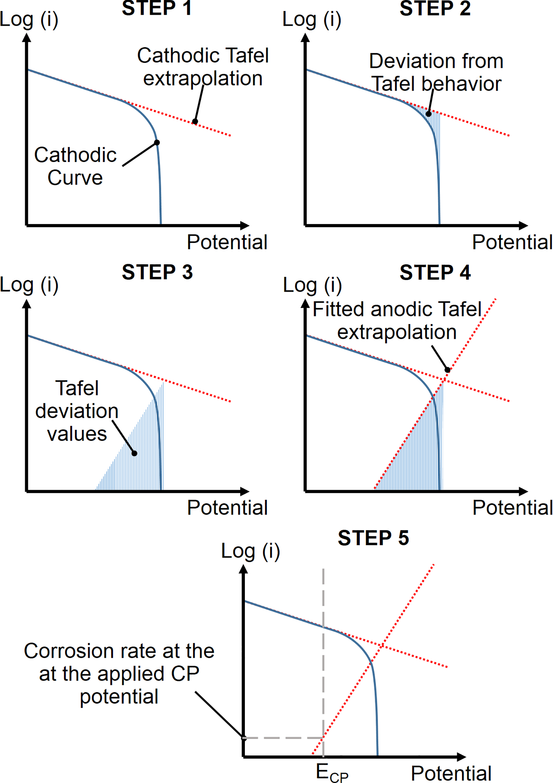
Calculation method to obtain the anodic Tafel relationship of a system from its cathodic polarisation curve
Galvanic probes
Probes consisting of on the pairs of API Grade A steel–stainless steel 304 and API Grade A steel–copper were tested by Choi et al. 78–80 A linear relationship between corrosion rates estimated by the API Grade A steel–copper probe and those estimated by EIS and LPR, in soils at OCP, was found. 79 Tests under CP in synthetic groundwater were also performed and a linear relation between probe current and CP current was found. 80 Although the results presented by Choi et al. seem to be promising, it has to be pointed out that under CP these probes monitor the effectiveness of the CP system, but provide no information regarding corrosion rates.
Multi-electrode arrays
These techniques simulate a continuous corroding surface by using probes consisting of several externally interconnected electrodes. Contrary to single electrode methods, these probes monitor localised corrosion because of the predominance of anodic or cathodic activity on each electrode, which can be measured. In addition, when a large number of closely small packed electrodes are used, high resolution maps of the electrochemical process can be obtained to study the mechanism of the corrosion process.81–83 The electrodes can be interconnected in different ways depending on the type of multi-electrode array (Fig. 8). The coupled multielectrode array sensor (CMAS) uses small fixed resistors between each electrode and one common terminal (shunt resistors).84,85 The potential drops at each of these resistors can be measured simultaneously by a multichannel high impedance voltmeter without interruption of any electrical connection (Fig. 8a). In this way, real time current distribution measurements can be performed.86–89 Unfortunately, the examples of these probes found on the literature show serious design drawbacks. The distance between electrodes was significantly large, reducing the electrochemical interaction between them. Also, a small number of electrodes were used, which did not allow the study of corrosion patterns. Instead, the data analysis technique used the mean value and standard deviation of the currents collected by all the electrodes in the array to calculate a probable maximum local corrosion rate. Although this method has been evaluated under CP, no correlation between measured and estimated corrosion rates was presented.88,89 The wire beam electrode (WBE) is a multi-electrode array design in which the external connections can be interrupted by a programmable multiplexer to interpose a zero resistance ammeter or a high impedance voltmeter and measure current or potentials distributions between the electrodes (Fig. 8b).81–83,90–92 This design has the advantage of avoiding the electrochemical perturbation produced by shunt resistors and the ability of allowing the use of more sophisticated electrochemical techniques such as LPR 82 and electrochemical noise. 93 When used under CP conditions, the current densities measured by the WBE are almost completely cathodic obscuring corrosion rate evaluations by direct use of Faraday's Law. However, a new data analysis method has been recently developed to estimate corrosion rates and distributions based on the different current magnitudes measured by each electrode under CP. 94
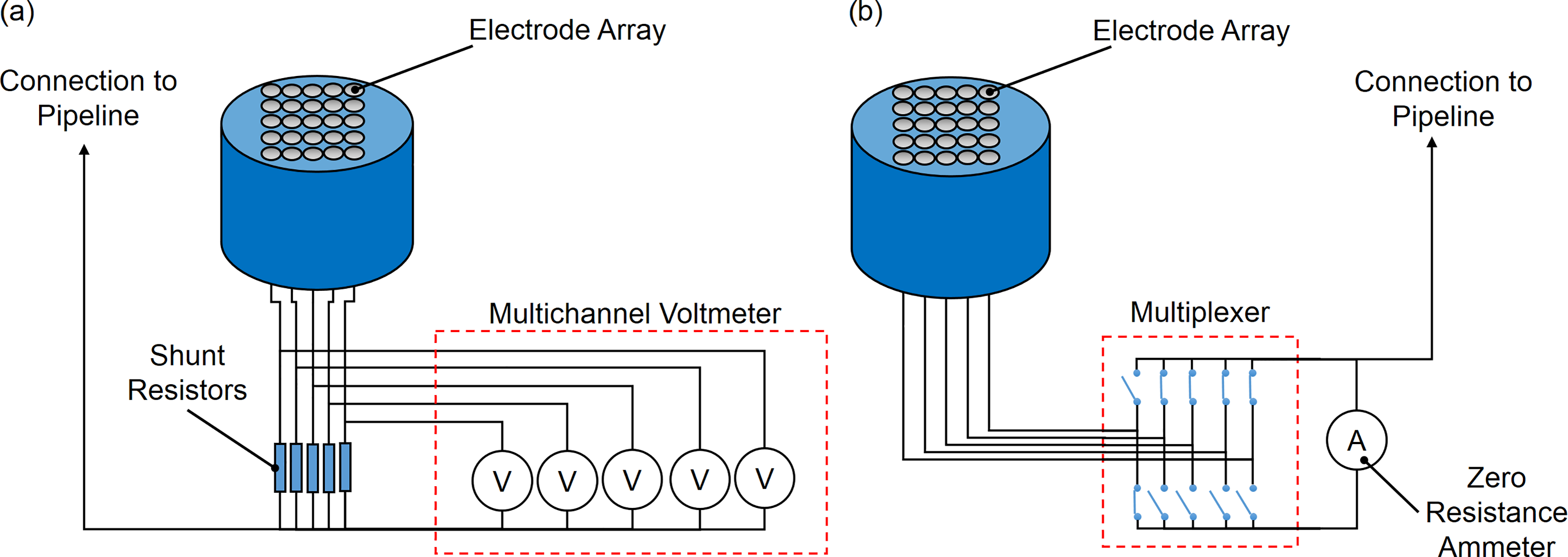
Multi-electrode arrays a coupled multielectrode array sensor (CMAS) and b wire beam electrode (WBE)
A major limitation associated with current electrochemical methods found in the literature is that the metallic surface is directly exposed to the environment not beneath a disbonded coating. Although some authors proposed the use of mathematical models to estimate the CP levels under disbonded coatings, the mechanism associated with critical localised corrosion issues are yet not well understood in order to be modelled.69,95
More research is currently being carried out to enhance the technological capability for pipeline engineers to monitor and capture pipeline coating deterioration and corrosion processes on a continuous basis. The principle of this pipeline condition monitoring tool is that real time monitoring of localised corrosion, ineffective CP, coating disbondment and degradation by placing sensors at strategic and ‘worst-case scenario’ locations of a pipeline would enable site-specific and in situ warning of pipeline failures. 96 These electrochemical methods have the potential of not only measuring corrosion rates but also more importantly they provide an insight into the electrochemical process. This is an invaluable contribution because measuring is the first step to understanding the electrochemical process leading to corrosion and to eventually help preventing it.
Concluding remarks
Various inspection techniques had been developed to thoroughly scrutinise buried pipelines, looking for metal losses or cracks that could had been produced by corrosion. These are not limited to the technologies used by ILI-tools and pipe crawlers, but also include the tools used during the ECDA dig up program. Although these tools produce a marked effect on safety by providing vital information for prioritising areas to be repaired, they provide little information regarding the causes of corrosion. Potential surveys such as CIPS and DCVG can provide valuable feedback on the effectiveness of the CP system and coating integrity, respectively. However, corrosion information obtained by these surveys is limited. Moreover, even when an accurate assessment of the coating and CP status are possible, correlating this information with corrosion rates is extremely difficult because soils are an inhomogeneous and dynamic environment.
Although currently less frequently used, corrosion monitoring tools can assist in obtaining in situ corrosion information. Non-electrochemical probes are generally less dependent on the characteristics of the corrosive environment and therefore may be easier to use. However, the assumptions taken when relating corrosion rates to other variables such as, ER, strain changes, etc. need to be valid in order to produce practical information. On the other hand, currently available electrochemical corrosion monitoring probes are challenged by the presence of coatings, CP and the resistivity of the soil. Traditional electrochemical techniques are not effective under these conditions, and this requires the development of new specific localised corrosion monitoring methods. The few electrochemical methods found in the literature have important limitations. With all of them, the metallic surface is directly exposed to the soil and none of them takes into account the conditions developed under disbonded coatings. Consequently, there is a need to expand the capabilities of electrochemical methods in order to be used in the pipeline industry.
Acknowledgements
The authors wish to thank Professor Bruce R. W. Hinton for his experienced advice, support and comments on the manuscript. The authors wish to thank Alan Bryson for sharing his first-hand experience on potential survey methods and general support. This work was funded by the Energy Pipelines CRC, supported through the Australian Government's Cooperative Research Centres Program. The funding and in-kind support from the APIA RSC is gratefully acknowledged.