
Abstract
In this study, the hot corrosion behaviour of Inconel 625 weldments in a molten lithium salt (LiCl–1 wt-%Li2O) was investigated at 650°C. The hot corrosion behaviour was observed through measurements of the oxide morphology, attack depth and compositional changes of the weldment. The corrosion products of as received (W625) and post-weld heat treated specimens (W625H) under isothermal load were Li4MoO5 and NiFe2O4, while FeNi3, Li4MoO5 and NiFe2O4 were identified as the corrosion products of as received cyclic specimens under cyclic heat load. The difference in weight loss between W625 and W625H was negligible, whereas very low weight loss was observed in cyclic specimens (W625C).
Introduction
Molten salt technology has been widely applied in industrial applications, such as salt bath brazing, 1 heat treatment of metals, 2 hazardous waste treatment 3 and metal recovery 4 because of the highly desirable physical and chemical characteristics of molten salts including high electrical conductivity, high processing rate and fluidity. However, molten salts can cause corrosion to container materials and various components of electrolysis equipment. Hence, studies on the corrosion of structural materials for handling high temperature molten salts are common in the literature.5–13 Ni based superalloys have been developed for high temperature applications due to their excellent resistance against corrosion at high temperature service conditions. This is why Ni based superalloys are considered as a corrosion resistant structural material for pyrochemical processing of spent nuclear fuels.
Pyroprocessing is one of the key technologies for reducing the amount of spent nuclear fuel and destroying toxic waste products, such as the long life fission products. 14 Pyroprocessing based on electrolysis using high temperature molten salts as the reaction medium involves the reduction of the spent oxide fuel to its metallic form, through an electrolytic reduction process operated in a LiCl–Li2O molten salt medium at 650°C.
However, if Ni -based superalloys encounter elevated temperatures in pyrochemical processes, especially welds of unit equipment made by conventional fusion welding have been found to be more prone to corrosion when being exposed to aggressive molten salt environments. The isothermal and cyclic corrosion tests are, therefore, a mainstay of material characterization characterisation and performance ranking for high temperature materials. Studies on the isothermal and cyclic hot corrosion behaviour of Ni based alloys are plentiful in the literature,15–19 whereas there are only a few reports on the isothermal and cyclic high temperature corrosion of Ni based superalloys in a molten lithium salt. Furthermore, the amount of information available about the hot corrosion behaviour of tungsten inert gas (TIG) welded Ni based alloys in molten lithium salt is very scanty. In order to apply Ni based alloys as structural materials for pyrochemical processes, especially at the commercial scale, welding is inevitable. Hence, the subject of the present investigation is to study the hot corrosion behaviour of TIG welded Ni based alloys in molten salt because the welded part could have different material properties, such as an inhomogeneous composition, coarse grain size and thermal stress.
In this study, molten LiCl–1 wt-%Li2O salt for the electrolytic reduction of spent oxide nuclear fuel was chosen as electrolyte for corrosion tests. The liberation of oxygen at the anode and the high temperature molten salts at 650°C create a chemically aggressive environment that is excessively corrosive for ordinary structural materials. 20 Therefore, there is a need for the proper selection of corrosion resistant structural materials that can be employed for this type of electrolytic reduction technology. Inconel 625 alloy was selected due to its excellent mechanical properties and corrosion resistance in high temperature atmosphere. The isothermal and cyclic corrosion behaviours of welded Inconel 625 have been investigated under simulated electrolytic reduction conditions.
Experimental
Materials and welding process
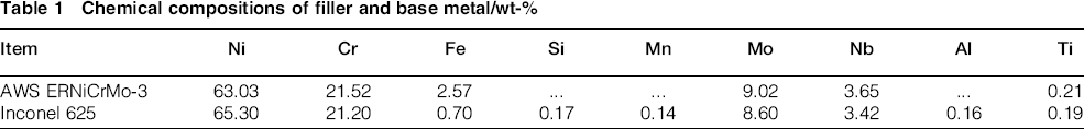
The present research was conducted on welded specimens composed of the base metal Inconel 625 and the wire filler metal AWS ERNiCrMo-3, similar to the alloy Inconel 625. The chemical compositions of the raw materials are listed in Table 1. The welds were made through the TIG welding process with a cold wire automatic feeding system. The TIG welding parameters were the welding current ranging from 120 to 140 A, welding voltage ranging from 12 to 14 V, welding speed ranging from 25 to 30 cm min− 1 and argon shielding gas flow of 15 L min− 1.
Chemical compositions of filler and base metal/wt-%
Specimen preparation
The specimens used for microstructural analyses were initially abraded by up to no. 1000 grit emery paper and finally polished by 1.0 μm diamond paste. Then, the polished specimens were etched using 25 mL of distilled water, 20 mL of 65% nitric acid, 20 mL of 32% hydrochloric acid and 10 mL of 30% hydrogen peroxide and were observed by a reflected light microscope (Nikon Optiphot 100s). To compare the corrosion behaviour of the weld zone (WZ), heat affected zone (HAZ) and base zone (BZ), the samples with dimensions of 70 × 15 × 3 mm were cut with the weld zone in the middle of the specimens. Before the corrosion tests, the specimens were ground with SiC paper (no. 2000), polished with diamond paste and cleaned in distilled water and acetone. Furthermore, to study the effect of a post-weld heat treatment (PWHT) on the corrosion behaviour of the as welded specimens, heating to 850°C for 2 h under argon atmosphere and subsequent cooling to room temperature were performed.
Hot corrosion tests
The experimental apparatus used for the corrosion tests is shown in Fig. 1. A molten LiCl–Li2O salt was introduced into a dense MgO crucible and then heated to 300°C for 3 h in argon atmosphere to remove any possible remaining moisture. After reaching the set conditions of 620°C, which is above melting point of LiCl–Li2O salt, the specimens and alumina tube were immersed into the molten salt, and a gas mixture (Ar–10%O2) was supplied through an alumina tube. The isothermal corrosion tests were carried out at 650°C for 168 h. In the case of cyclic corrosion test, the specimens were kept at 650°C for 24 h with 6 h heating up to the test temperature and 48 h cooling down to room temperature, which is 1 cycle. Hence, each cycle takes 78 h and 7 cycles were conducted for cyclic corrosion test. The cyclic corrosion tests simulated the real operation mode of electrolytic reduction processes in which heating up to the reactor operation temperature and cooling down to room temperature alternates periodically. The Li2O concentration in LiCl was 1 wt-%. Following the corrosion test, the specimens were withdrawn from the salt and kept under argon gas atmosphere while the furnace was cooled down to room temperature.
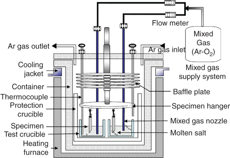
Schematic diagram of apparatus used for corrosion tests
Characterisation
After the reactor was opened, the specimens were removed for visual examination. The specimens were then ultrasonically cleaned in deionised water, measured and weighed. The initial and final weights of the specimens exposed to the molten salt was recorded to assess the extent of the reaction. The corroded specimens were then cut using a diamond cutter and ultrasonically cleaned in acetone for characterisation purposes. Some specimens were prepared for metallographic examination by cold mounting, grinding and polishing. The microstructure, morphology and chemical composition of the surface and cross-section of the corroded specimens were examined using a scanning electron microscope (SEM; JEOL, JSM-6300) equipped with an energy dispersive spectrometer (EDS). X-ray diffraction (XRD; Rigaku, DMAX/1200) analysis was used to determine the structure of the hot corrosion products. For the measurement of the alloying elements dissolved in the molten salt after the corrosion tests, a sample was weighted in a glove box and then dissolved with 3 mL of HCl and 3 mL of HNO3 on a hot plate. A sequentially working inductively coupled plasma atomic emission spectrometer system (Horiba Jobin Yvon SAS, France) was used to measure the elements Ni, Fe, Cr, Mo and Nb in the solution.
Results and discussion
Optical microstructure of weldments
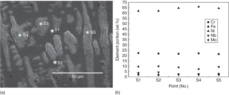
Figure 2 presents the optical micrograph near the TIG weld junction. Three different parts, namely, the WZ, HAZ and BZ, can be seen in the cross-sectional image of the TIG joint, as illustrated in Fig. 2. No cracks or porosities were observed at the interfaces of the different zones of the weldment. The bulk structure of the weldment zones did not reveal any marked changes between as received (W625) and PWHT specimens (W625H). Fine dendritic grain structures were observed in the WZ of W625 and W625H due to the melting and cooling during the complete welding process.21–23 In the case of HAZ, recrystallised grains with some fibrous tissues near the boundary were observed. 24 The chemical composition of the WZ showed segregation of the elements Nb and Mo to the regions (S1, S2 and S3), whereas elements such as Ni and Fe showed a slight depletion in the these regions, 21 as shown in Fig. 3. By the EDS point analysis, interdendritic area, S1, S2 and S3 in Fig. 3 show increase in Nb (mean, 5.65 wt-%) and Mo (mean, 10.32 wt-%), while concentrations of Ni (mean, 59.10 wt-%) and Fe (mean, 3.49 wt-%) are relatively low. In the case of dendritic structure (S4, S5 and S6), however, concentrations of Ni (mean, 63.88 wt-%) and Fe (mean, 3.87 wt-%) are higher than that at the interdendritic area, while the concentrations of Nb (mean, 2.17 wt-%) and Mo (mean, 8.43 wt-%) are decreased. After heat treatment, as shown in Fig. 4, interdendritic area (S1 and S2), concentrations of Nb (mean, 4.1 wt-%) and Mo (mean, 9.79 wt-%) are slightly high and those of Ni (mean, 61.89 wt-%) and Fe (mean, 2.09 wt-%) are relatively low. In the case of dendritic area (S3, S4 and S5), the concentrations of Ni (mean, 64.96 wt-%) and Fe (mean, 2.65 wt-%) slightly increase and those of Nb (mean, 2.08 wt-%) and Mo (mean, 8.56 wt-%) slightly decrease. Hence, it was certain that elemental distribution became homogeneous after heat treatment from the EDS analysis data in Fig. 4b. It is not favourable to have such a dendritic microstructure with inhomogeneous element distribution because corrosion is initiated at grain boundaries in WZ. Therefore, a small grain size may lead to the rapid formation of an oxide layer due to grain boundary diffusion. 22 Generally, grain boundaries provide paths of fast diffusion within the matrix compared to the slow lattice diffusion inside of the grains. For this reason, oxygen can easily penetrate into the matrix, and alloying elements from the matrix can easily move out along the grain boundaries. Post-weld heat treatment is a treatment that changes the grain structure in order to achieve mechanical properties similar to the base metal, which means release of residual stress in the WZ. Hence, the PWHT would contribute to the corrosion resistance enhancement not only due to the release of residual stress but also by homogenisation of the alloying elements especially for the precipitates.
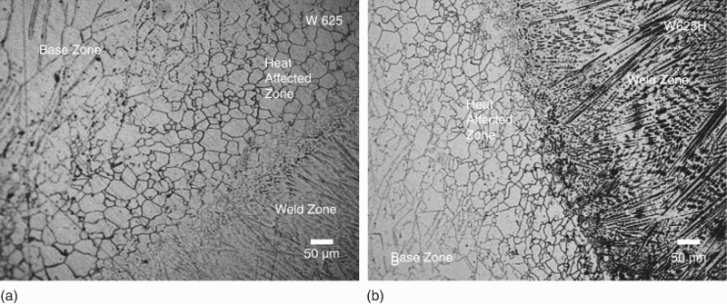
Microstructures of a as welded W625 and b heat treated W625H after etching
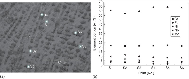
a cross-sectional SEM image and b result of EDS analysis of enlarged weld zone of W625
a cross-sectional SEM image and b result of EDS analysis of enlarged weld zone of W625H
Mass loss and attack depth
The weight losses of W625, W625H and W625C of welded Inconel 625 after the corrosion tests in molten LiCl–1 wt-%Li2O salt at 650°C for 168 h and 7 cycles are presented in Fig. 5. As evident from Fig. 5, the weight losses of W625 and W625H showed only a small difference, while W625C exhibited the lowest weight loss. It is expected that the weight loss of W625H is lower than that of W625 due to the minimisation of residual stress and homogenisation of the alloying elements, whereas it is unusual that W625C has the lowest weight loss considering that it was subject to the most harsh corrosion conditions. In order to understand the unusual tendency of the isothermal and cyclic corrosion rate of the welded specimens, the attack depth was investigated. Here, the attack or penetration depth is defined as the sum of the thicknesses of the internal and external corrosion layers. The attack depths of W625, W625H and W625C after the isothermal and cyclic corrosion tests in molten LiCl–1 wt-%Li2O salt at 650°C for 168 h and 7 cycles are shown in Fig. 6a and b respectively. As a result, the penetration depth of the specimens well agreed with the data of the weight loss measurements. W625 shows the largest attack depth in the HAZ, and also the BZ has a relatively deep attack depth, as shown in Fig. 6b. It was found that the attack depths significantly decreased by the heat treatment, compared to the as welded specimens, as shown in Fig. 6b. W625C showed the lowest attack depth at BZ, illustrated in Fig. 6b. Based on the results of the penetration depth measurements, the difference between the corrosion rate of W625 and W625H is expected to become larger with increasing corrosion time, possibly due to residual stress induced during the welding process. The cyclic corrosion environment is supposed to be more severe than the isothermal one. However, W625C exhibits superior corrosion behaviour in terms of the weight loss data displayed in Fig. 5 and attack depth measurements presented in Fig. 6b. There is a clear difference in the number of interfacial defects between the corrosion layer and the matrix in W625C, compared to the other specimens that were subject to isothermal corrosion tests, as shown in Fig. 6. The defects, such as pores and cracks at the interfaces of W625C, are believed to be formed during thermal cycling due to the different thermal expansion coefficients of the corrosion products of the corrosion layers. If the corrosion layer is not sufficiently dense, electrolyte could penetrate into the defects. In this case, the corrosion should be accelerated with progressing corrosion time. However, in this corrosion experiment, the dense corrosion layer retarded the penetration of electrolyte, and the defects also may decrease the diffusion rate of oxygen ions into the matrix. Irrespective of the origin of the exceptionally low attack depth of W625C, compared to W625 and W625H, it does not mean that the corrosion rate of W625C is lower than that of the other specimens because the present results are limited to the initial stage of the corrosion reaction. It is anticipated that there will be catastrophic failure of the corrosion layer if thermal cycling is proceeded further. This means that the cyclic corrosion environment is more severe than the isothermal corrosion, especially for the WZ, because the attack depth increases and cracks form in the WZ, HAZ and BZ of W625C specimens.
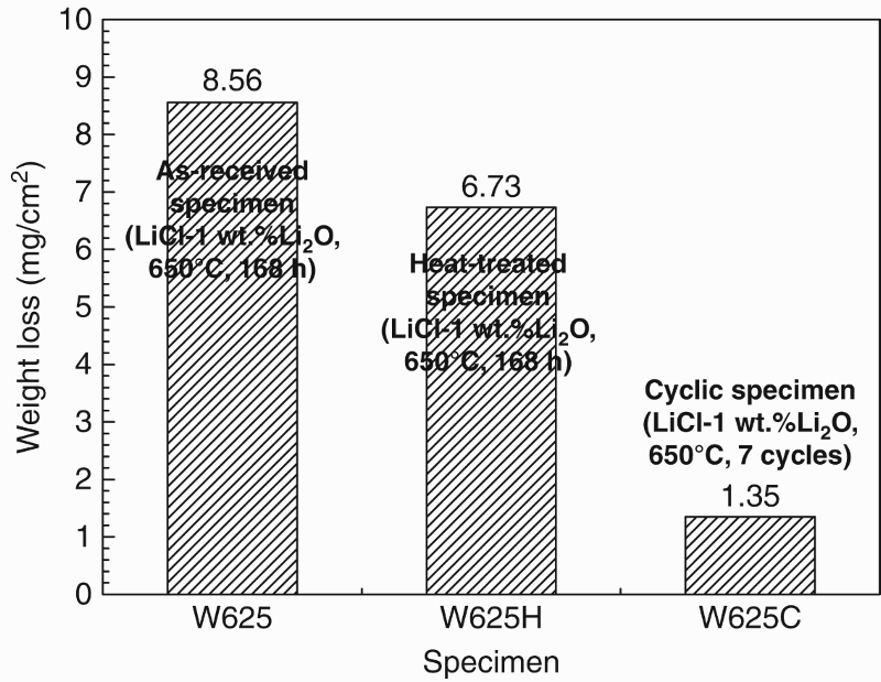
Weight loss of welded Inconel 625 specimens corroded at 650°C for 168 h and 7 cycles
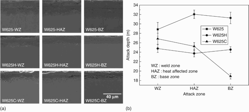
a microstructural changes in surface corrosion layer and b variation of attack depth of welded Inconel 625 specimens corroded at 650°C for 168 h and 7 cycles
Corrosion products
Figure 7 shows the XRD patterns of the corrosion products after the isothermal and cyclic corrosion tests in molten LiCl–1 wt-%Li2O salt at 650°C for 168 h and 7 cycles. The corrosion products of W625 were Li4MoO5 and NiFe2O4 and those of W625H, likewise isothermally corroded for 168 h, were Li4MoO5 and NiFe2O4. Li4MoO5, NiFe2O4 and FeNi3 were identified as the corrosion products of W625C, corroded for 7 cycles. Concerning the corrosion product Li4MoO5, it is attributed to the outward diffusion of Mo and its reaction with the Li based molten salt. Consequently, the formation of the corrosion products in an oxidative, Li based molten salt depends on the thermodynamic stability of the oxide formation reaction along with the diffusion of the constituent elements and the Li ions. In case of NiFe2O4, this spinel was formed by the solid phase reaction of NiO and Fe2O3. 25 The alloying elements dissolved in the molten salt are listed in Table 2. As evident from the metal concentrations shown in Table 2, the external diffusion rates of Fe and Mo at high temperature seem to be faster than that of the element Cr. 26 In addition, the concentration analysis data of elements dissolved in molten salt show that corrosion rate of W625C was significantly affected due to small amount of corrosion products. In the case of W625C, the diffraction pattern of the corrosion products presented in Fig. 7c shows the existence of FeNi3. It is believed that Fe diffused to the surface and then formed the intermetallic phase with Ni.
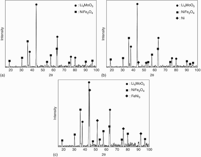
X-ray diffraction patterns of corrosion products of a W625, b W625H and c W625C corroded at 650°C for 168 h and 7 cycles
Alloying elements dissolved in molten salt after hot corrosion tests
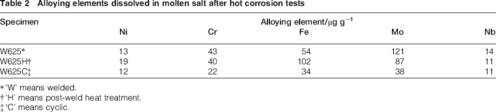
‘W’ means welded.
‘H’ means post-weld heat treatment.
‘C’ means cyclic.
Corrosion behaviour
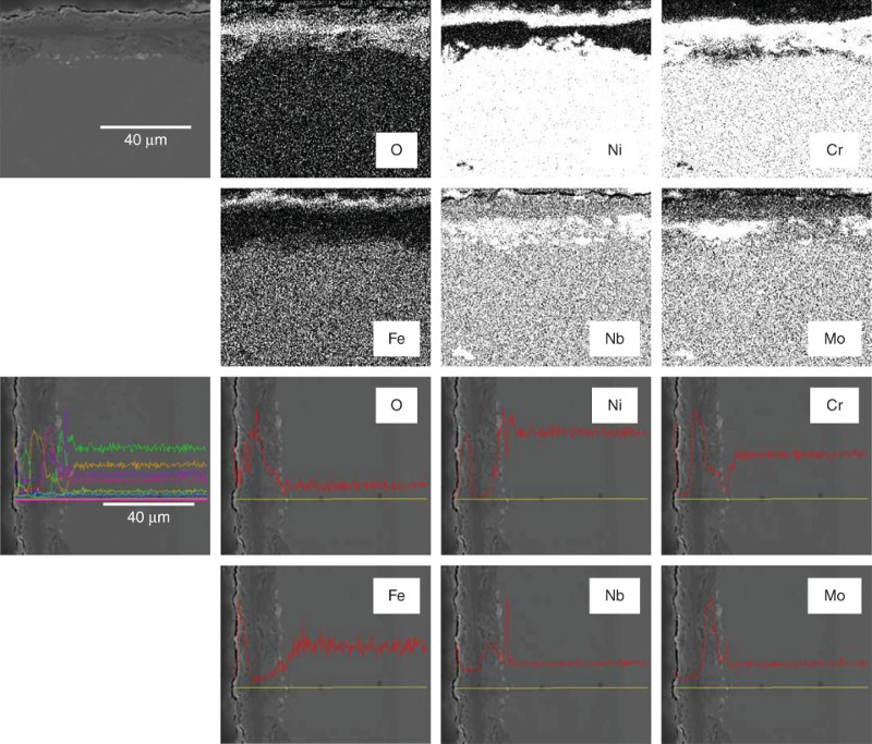
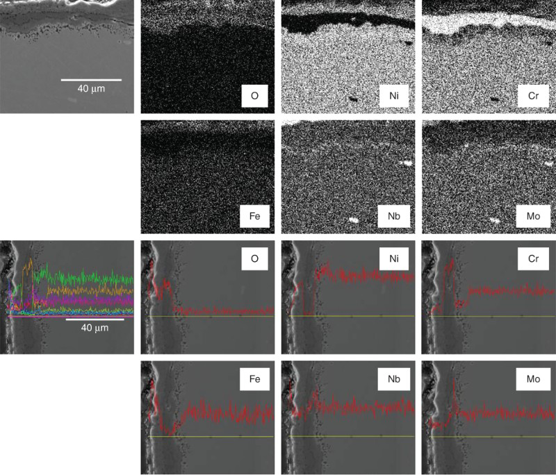
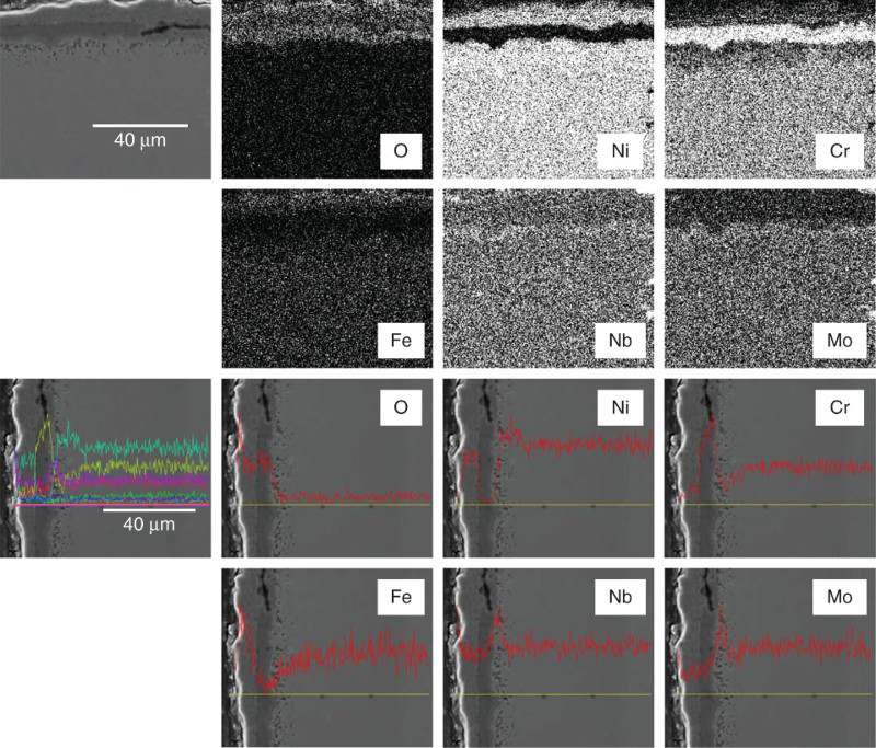
Figure 8 shows the cross-sectional SEM image and elemental maps of the WZ of W625 corroded at 650°C for 168 h in molten LiCl–1 wt-%Li2O salt. Figures 9 and 10 show the corresponding cross-sectional SEM images and elemental maps of the HAZ and BZ of W625 respectively. Figure 8–10 clearly indicate that external and internal corrosion layers are composed of Ni and Cr rich oxides respectively. The interface between Ni and Cr rich oxide in the WZ is not straight, as opposed to the other specimens, but serpentine, as shown in Fig. 8. The corrosion layer mainly consisted of Cr based oxide with a band of (Nb, Mo) based oxides, as shown in Figs. 8 and 10. The Nb, Mo complex oxide layer has different thermomechanical properties compared with the other oxide layers that are composed of, for example, Fe, Ni and Cr oxides. This means that the oxide layers are easily exfoliated due to different thermal expansion coefficients. Contrary, the Nb, Mo complex oxide layer beneath the surface of the corrosion layer could prevent internal diffusion of oxygen and outer diffusion of alloying elements and, thereby, may enhance the corrosion resistance.
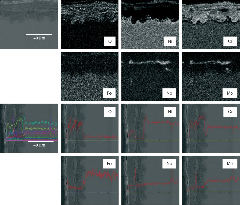
Cross-sectional micrograph and maps of Ni, Cr, Fe, O, Nb and Mo and cross-sectional micrographs with EDS line scans of weld zone of W625 corroded at 650°C for 168 h in LiCl–1%Li2O molten salt
Cross-sectional micrographs and maps of Ni, Cr, Fe, O, Nb and Mo and cross-sectional micrographs with EDS line scans of heat affected zone of W625 corroded at 650°C for 168 h in LiCl–1%Li2O molten salt
Cross-sectional micrographs and maps of Ni, Cr, Fe, O, Nb and Mo and cross-sectional micrographs with EDS line scans of base zone of W625 corroded at 650°C for 168 h in LiCl–1%Li2O molten salt
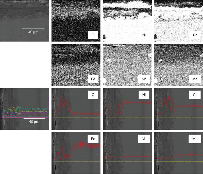
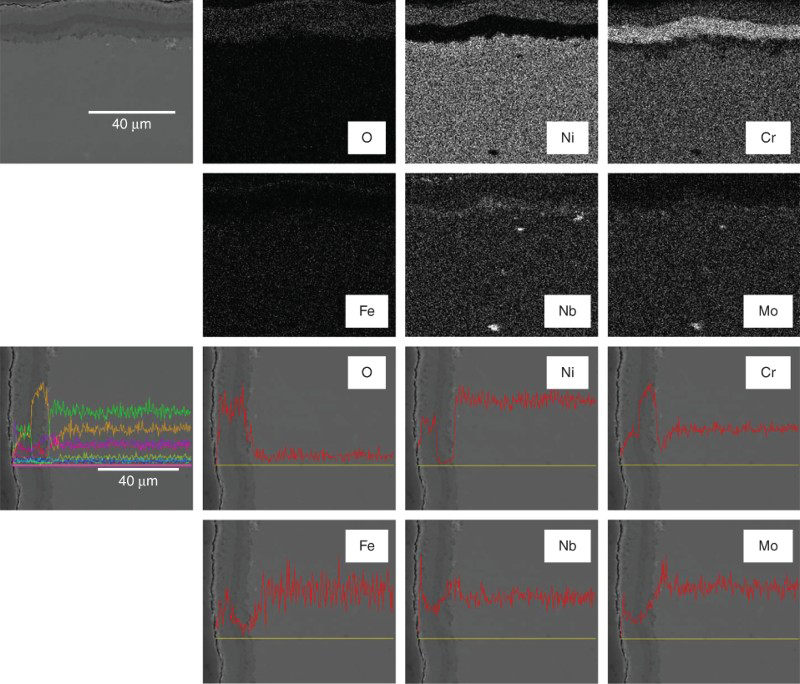
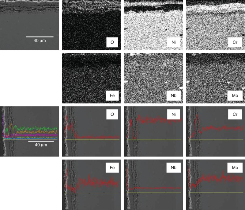
Figure 11 shows the cross-sectional SEM image and elemental maps of the WZ of W625H corroded at 650°C for 168 h in molten LiCl–1 wt-%Li2O salt. Figures 12 and 13 show the corresponding cross-sectional SEM images and elemental maps of the HAZ and BZ of W625H respectively. It was found that the elemental distribution in the WZ of W625H is different from that of W625 without irregular interface between the Cr rich corrosion layer and Ni, as observed in Fig. 8. The oxide layer of W625H is composed of Ni, Cr, Mo and Nb rich oxides occurring sequentially from the surface of the corrosion layer, as shown in Fig. 12. Such mixed oxide layers seems to be favourable to mitigate the acceleration of the corrosion rate by preventing exfoliation of the corrosion layers. The HAZ and BZ of W625H also show similar corrosion behaviour after the corrosion tests, as shown in Figs. 12 and 13 respectively, implying a lower corrosion rate compared to that of W625. These microstructural characteristics and elemental distributions in the corrosion layers well account for the lower corrosion attack depths of the heat treated samples.
Cross-sectional micrographs and maps of Ni, Cr, Fe, O, Nb and Mo and cross-sectional micrographs with EDS line scans of weld zone of W625H corroded at 650°C for 168 h in LiCl–1%Li2O molten salt
Cross-sectional micrographs and maps of Ni, Cr, Fe, O, Nb and Mo and cross-sectional micrographs with EDS line scans of heat affected zone of W625H corroded at 650°C for 168 h in LiCl–1%Li2O molten salt
Cross-sectional micrographs and maps of Ni, Cr, Fe, O, Nb and Mo and cross-sectional micrographs with EDS line scans of base zone of W625H corroded at 650°C for 168 h in LiCl–1%Li2O molten salt
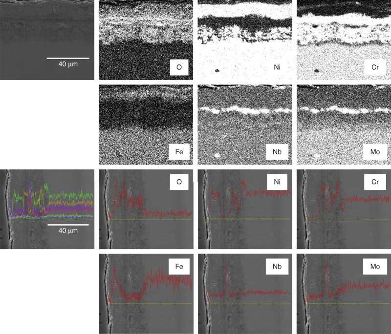
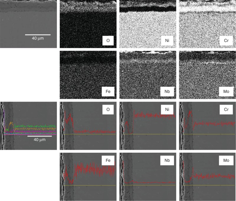
Figure 14 shows the cross-sectional SEM image and elemental maps of the WZ of W625C corroded at 650°C for 7 cycles in molten LiCl–1 wt-%Li2O salt. Figures 15 and 16 show the corresponding cross-sectional SEM images and elemental maps of the HAZ and BZ of W625C respectively. A distinctive feature of the corrosion layer of W625C is the formation of defects at the interface between corrosion layer and matrix, whereas there is no serpentine shaped Cr rich oxide layer that is observed at the WZ of W625 in Fig. 8. Cracks under the corrosion layer would significantly increase the corrosion rate due to exfoliation of the corrosion products.
Cross-sectional micrographs and maps of Ni, Cr, Fe, O, Nb and Mo and cross-sectional micrographs with EDS line scans of weld zone of W625C corroded at 650°C for 7 cycles in LiCl–1%Li2O molten salt
Cross-sectional micrographs and maps of Ni, Cr, Fe, O, Nb and Mo and cross-sectional micrographs with EDS line scans of heat affected zone of W625C corroded at 650°C for 7 cycles in LiCl–1%Li2O molten salt
Cross-sectional micrographs and maps of Ni, Cr, Fe, O, Nb and Mo and cross-sectional micrographs with EDS line scans of base zone of W625C corroded at 650°C for 7 cycles in LiCl–1%Li2O molten salt
From this series of experiments on the corrosion characteristics of Inconel 625 weldments in dependence of the corrosion and heat treatment conditions of the welded samples, Inconel 625 alloy was found to be one of the most effective alloys for pyroprocessing of spent nuclear fuel, especially for the electrolytic reduction process. Hence, these experimental results could contribute to the most appropriate choice of structural materials for pyroprocessing and its realisation at the commercial level.
Conclusions
The hot corrosion behaviour of Inconel 625 weldments was investigated under isothermal and cyclic corrosion environments. The corrosion rate including the attack depth for the experimental corrosion time of 168 h and 7 cycles was in the order of W625C < W625H < W625, showing an increase in the corrosion rate with progressing corrosion time under the high temperature and oxidative environment of a molten Li salt. The lower penetration depth of W625C was found to be caused by defects underneath the dense corrosion layer that retarded the diffusion of oxygen ions into the matrix within the seven corrosion cycles in this study. However, the defects formed by cyclic corrosion test would deteriorate the corrosion resistance of the alloy at the longer corrosion cycle. The heat treatment significantly contributed to corrosion enhancement by homogenisation of alloying elements, and it was confirmed by microstructural evaluation of heat treated specimen and the analysis of dissolved elements in molten salt. The corrosion products of W625 were Li4MoO5 and NiFe2O4, and those of W625H were Ni, Li4MoO5 and NiFe2O4, whereas FeNi3, Li4MoO5 and NiFe2O4 were identified as the corrosion products of W625C. The spallation of oxides in the molten salt might be attributed to their different compositions, their thermal stress caused by their different thermal expansion coefficients between corrosion layer and matrix and uniformity of the alloying element in dendritic microstructure especially in weld parts. The corrosion resistances of welded Ni based superalloys in molten lithium chloride salt at high temperature during isothermal and cyclic corrosion tests are strongly related to the arrangement of the formed oxides in the corrosion layer and the PWHT.
Acknowledgements
This work was funded by the National Mid- and Long-Term Atomic Energy R&D Program supported by the Ministry of Science, ICT and Future Planning.