
Abstract
In this paper, a procedure for prepitting of pipeline X-52 steel in the bicarbonate/carbonate solution was developed. Sodium chloride was added to the solution to induce pitting, and the optimum concentration of chloride ions, which produced a low density of pits, was found. The procedure briefly included prepassivation of the steel in the solution with optimum concentration of chloride ions and then increasing the potential above the pitting potential to generate pits. The potential was then stepped back well below the pitting potential to grow the pits to the desirable depth. This procedure can be used to generate pits on tensile specimens, which can be subsequently employed in near neutral pH stress corrosion crack initiation studies. This can result in shorter duration of crack initiation experiments under real loading condition.
Introduction
Stress corrosion cracking (SCC) of pipeline steels has been known to be a major threat for both gas and oil pipelines since 1960s when the first rupture of pipelines due to SCC occurred. The two forms of SCC detected so far are known as high pH SCC and near neutral pH SCC referring to the aqueous environment found under the coating when cracking is produced. In the case of near neutral pH SCC on which this paper focuses, the crack initiation step takes the main portion of pipeline life. It takes several years after coating failure for cracks to initiate in the pipelines, and this kind of crack is most likely to initiate from the bottom of corrosion pits.1–3 Corrosion pits are known to have two adverse effects. First, producing an aggressive localised environment inside the pits can maintain an active state at the pit bottom; whereas, outside, the pit may be passive. This aggressive solution inside the pits is characterised by a higher aggressive ion concentration and a lower pH. 4 Second, pits acts as stress risers and cause higher stress levels, which sometimes may reach the plasticity limit. As mentioned by some researchers, plastic deformation around the pits can enhance corrosion since the strained region has a higher internal energy level and is more prone to corrosion. 5
Crack initiation has been a topic of interest for researchers in the last several years, but since its experiments are long term (it takes several years for pits to develop and grow to cause cracking in the field), the amount of research around crack initiation has been limited. It has been shown in a recent research paper that no cracks nucleated from the bottom of pits under a realistic condition in the near neutral pH environment even after 3 months of loading. 6 Therefore, some researchers have used accelerated laboratory tests to study the crack initiation process, but under these conditions, pits may not grow to critical size before initiation of cracks, and in this way, the effect of pits on crack initiation may be underestimated. 7 On the other hand, there is still a lack of knowledge on conditions favourable for pit to crack transition especially in the case of near neutral pH SCC. Conducting crack initiation tests with prepitted specimens can, on the one hand, reduce the duration of the tests and, on the other hand, enable researchers to further investigate pit to crack transition conditions. Therefore, the objective of this paper is to develop an electrochemically accelerated method to generate a low density of pits on the surface of X-52 pipeline steel for subsequent corrosion fatigue experiments to study pit to crack transition and crack initiation from pits. It was deemed desirable to learn more about pit characteristics in bicarbonate/carbonate solution, which was used as the pitting generation solution in this study and is believed to cause high pH SCC in pipelines.
Experimental
Material
An API 5L X-52 pipeline steel, which had been in service for more than 10 years, was used in this study. Figure 1 shows the SEM image of the pipeline steel microstructure, which is mainly composed of ferrite and pearlite. X-52 pipeline steel with this microstructure has been already shown to be prone to both types of SCC. 1 The outside diameter and thickness of the pipeline were 762 and 9.53 mm respectively. Specimens with dimensions of 25 × 10 × 4 mm were cut from the pipeline for the experiments. The specimens were mounted in epoxy and then ground up to 1200 grit SiC paper and cleaned in ethanol. To avoid any crevice corrosion at the interface of samples and epoxy during the experiments, these interfaces were covered with a high performance sealant.
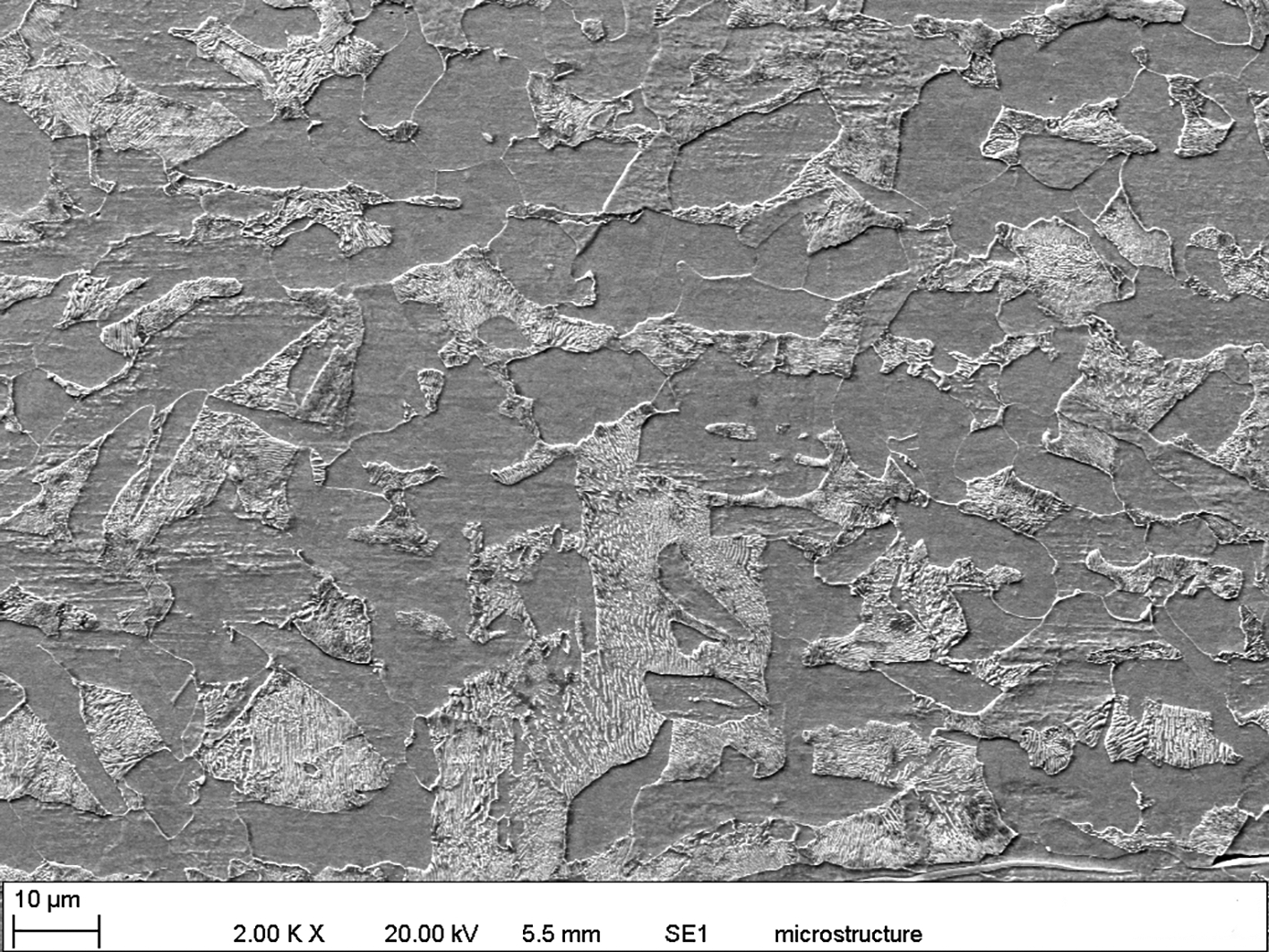
Microstructure of X-52 pipeline steel used in this study
Experimental procedure
To select an appropriate solution for generating pits on the samples, the following considerations were made.
On the one hand, the near neutral pH ground water found in the field where near neutral SCC was detected could not be used for prepitting the samples because it does not form a passive layer and the pitting process itself at OCP condition would take a long time (several years) in the field depending on the microstructure of the steel, the level of inclusion, etc., and that is the motive for developing a prepitting procedure to reduce the duration of crack initiation from pits. On the other side, it is known that, during both high pH and near neutral pH SCC, ground water penetrates inside a disbonded coating. In the former, since cathodic current reaches the pipeline inside the disbondment, cathodic reactions occur on the exposed pipeline area, causing the generation of hydroxyl ions and therefore increasing the pH of the ground water. However, in the latter, cathodic current does not reach the pipeline inside the disbondment because of either the shielding effect of coating or high resistance soils surrounding the pipe, and this causes the pH to remain in a near neutral range. The difference between these two ground water solutions in terms of pitting corrosion is that the former, high pH SCC solution, forms a passive layer on the surface of pipeline steel, and pitting process and depth of pits could be controlled by controlling the potential, but as mentioned before, the latter does not have such a capability. Therefore, it is believed that using simulated ground water solution in the case of high pH SCC could have less effect on further crack initiation in near neutral pH ground water compared to other regular solutions including any aggressive acids, which promote pits on the surface of steels but may cause hydrogen charging into the specimens and could affect subsequent crack initiation from pits.
After taking these considerations into account, a bicarbonate/carbonate solution (0.5M NaHCO3+0.25M Na2CO3), which is believed to cause high pH SCC in pipeline steels, was selected as the base solution. NaCl was added to the base solution to induce pitting on the surface of the samples. A series of cyclic polarisation experiments were performed at different concentrations of NaCl to determine the optimum NaCl concentration. Before the cyclic polarisation experiments, the samples were exposed to the solution for 1 h, and open circuit potential was monitored by a Gamry PC4/300 potentiostat during this time. Cyclic polarisation experiments were then conducted from an initial potential 50 mV below the open circuit potential with a scanning rate of 1 mV s− 1 until a threshold current density of 0.1 mA cm− 2 was reached. Each cyclic polarisation test was repeated three times to ensure the reproducibility of results.
After determining the optimum concentration of NaCl, a series of polarisation experiments were performed to generate small pits on the surface of samples. The general procedure for generation of pits includes initially passivating the surface at a passivating potential for a short period of time and then increasing the potential above the pitting potential, obtained by cyclic polarisation tests performed in the solution with optimum NaCl concentration, for a limited time and then decreasing the potential below the pitting potential to grow the pits without generating new ones. After each experiment, corrosion products inside and at the pit mouth were removed using ethylenediaminetetraacetic acid solution. Then, surface and depth analyses were performed on the pits using a Keyence microscope equipped with VHX-700F software capable of three-dimensional imaging.
Results and discussion
Corrosion potential measurements
Figure 2 shows the measured values of the corrosion potentials of X-52 pipeline steel immersed in the base solutions with and without addition of selected concentrations of NaCl. According to Fig. 2, corrosion potentials in all solutions had an increasing trend with time owing to the growth and thickening of the passive film. It should be mentioned that, in some solutions, an initial decrease in potential was observed, which is caused by the initial dissolution of iron before passivation. In some solutions, the corrosion potential did not reach a steady state value within 1 h. Long term exposure to the solutions showed that corrosion potential in these solutions reached a relatively stable value after 2-3 days, and the highest potential of − 0.15 mV (SCE) was reached after 3 days in the case of the base solution. Moreover, the corrosion potential in the solution with 0.2M NaCl started to decrease after ∼3 h, which can be attributed to instability and breakdown of the passive layer in this solution. Overall, Fig. 2 also shows that corrosion potentials move towards more negative values with increasing concentration of NaCl, indicating that chloride ions enhances the activity of the metal during exposure to the base solution. However, up to a NaCl concentration of 0.03 M, this negative shift in initial and final corrosion potentials is not significant.
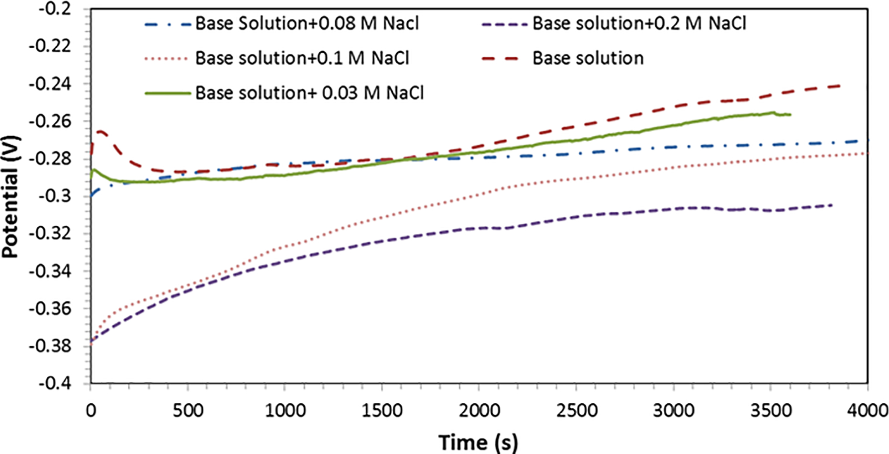
Corrosion potentials versus time measured at solutions with different concentrations of NaCl
Cyclic polarisation tests
Figure 3 shows the results of cyclic polarisation tests at different concentrations of NaCl. It is obvious that, in all solutions up to concentrations of 0.1M NaCl, a stable passivity range is observed, indicating that these solutions produce a passive layer on the X-52 steel. Two distinct current peaks can be observed in these solutions during the forward scan. These two peaks are formed corresponding to the formation of two distinct passive layers on the surface of steel. Upon immersion of the specimen in the solutions and the positive shift of potential, iron actively dissolves, and therefore, the current increases. With further increases in both potential and concentration of iron ions, the solubility limit of iron carbonate is exceeded and iron carbonate deposits on the surface. 8 Formation of both Fe(OH)2 and FeCO3 causes the first peak in the current at potential around − 0.2 V (SCE). With a further positive shift of potential, these two passive layers will become unstable and are converted to more stable oxide layers of Fe2O3 and Fe3O4 causing a second peak at ∼0.14 V (SCE). The appearance of these two peaks in bicarbonate/carbonate solution is in a good agreement with reports in the literature, and this has been well studied before.8–10
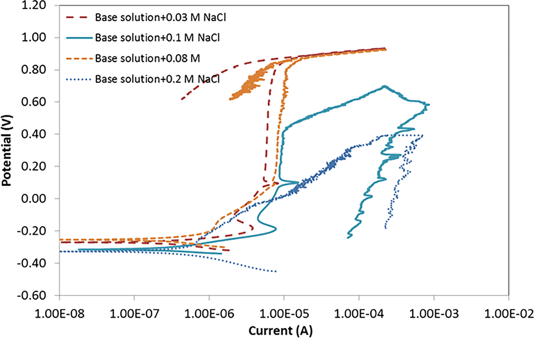
Cyclic polarisation curves measured in solutions with different concentrations of NaCl
According to Fig. 3, no pitting occurred on the surface of the steel up to a concentration of 0.08M NaCl, since it is observed that the current measured during the reverse scan in these solutions was lower than that in forward scan, indicating that the sample surface remained passive during the reverse scan. Surface analysis after the tests also showed no evidence of pitting on the surface of specimens immersed in these solutions. On the other hand, addition of chloride ions increased the passivity current but had no significant effect on the transpassive potential, and the passivity potential ranges up to concentrations of 0.08M NaCl. The increase in passivity current caused by the addition of chloride ions has been attributed to the adsorption of chloride ions on the passive layer and subsequent thinning of the passive layer and establishment of a new stationary state with higher dissolution of iron. 11 At a concentration of 0.1M NaCl, the passive potential range was reduced, and pitting occurred at a potential ∼0.4 V (SCE). This was inferred both from surface analysis after the test and the fact that current during reverse scan was higher than the forward scan. Since the reverse scan curve did not intersect the forward current in the passivity range even at lower threshold current levels, no protection potential was obtained for this solution (0.5M NaHCO3+0.25M Na2CO3+0.1M NaCl), which is perhaps because of the large surface area exposed to the solution. With further increases in concentration of NaCl, the passivity range decreased further until it was no longer present at a concentration of 0.2M NaCl, and the X-52 steel showed active metal dissolution behaviour in this solution.
Clearly, solutions with NaCl concentration < 0.1M are too passive, and solutions with higher NaCl concentrations are too aggressive to produce pits on the surface of X-52 pipeline steel. The 0.5M NaHCO3+0.25M Na2CO3+0.1M NaCl solution provided a balance between passivition of and aggressiveness towards the steel by the environment and therefore was selected for pit generation on X-52 specimens.
Pitting procedure
Broadly speaking, there are two methods for producing pits on the surface of specimens, either galvanostatic (current control) or potentiostatic (potential control). They are considered in turn.
In the galvanostatic method, the specimens are immersed in a pit promoting solution at the corrosion potential for a specific period of time during which their surface is passivated. Then, a fixed anodic current is applied to generate pits. 12 The pitting potential in this method depends on the immersion time; however, it takes a long time for the passive layer to reach a stable state, but before this time is reached, the passive layer is unstable and may vary from one sample to another. For this reason, the current method is time consuming and may be unreliable.
In the potentiostatic approach, the surface of the specimen is passivated for a constant time to ensure that the surface condition before generating pits is the same in all specimens. The results are more reliable and less time consuming. Thus, this approach is preferred. In the pitting procedure developed here, prepassivation of the surface was performed at 0.13 V (SCE), a little higher than the potential at second peak in cyclic polarisation curves (Fig. 3) and well below the pitting potential [0.4 V (SCE)] to avoid risk of formation of any unstable pits during passivation. Duration of prepassivation was selected to be 300 s because it was found that this time caused pit initiation in a reasonable time. Longer passivation times produced a thicker passive layer, making pitting initiation more difficult. In order to initiate pits after passivation, the electrode potential was increased to a potential above the pitting potential, i.e. 0.4 V (SCE). However, maintaining the sample at this potential to obtain desirable pit depth generates too many pits, which are too near each other. To eliminate continued initiation, the electrode potential was stepped to a lower potential below the pitting potential [0.13 V (SCE)] but above the corrosion potential. This continues to grow pits already initiated but avoids formation of any new pits.
Some preliminary experiments were performed, and it was found that a pit initiation duration of 50 s was enough to generate sufficient pits on the surface. The pits were then grown for a further 2 h at the growth potential. This produced a maximum pit depth of 100 μm. This maximum depth value was selected based on the fact that most of the observed small cracks found in crack colonies in the field have been reported to have a depth of ∼0.5 mm. 13 Also since the thickness of tensile samples used in the subsequent corrosion fatigue tests was 4 mm, selecting a larger depth limit could reduce the cross-section significantly and, consequently, may affect crack initiation. Pit generation experiments were initially conducted in a static solution for the test duration, but since microscopic analysis after the tests revealed that localised corrosion occurred at the open mouth of the pits from the accumulation of aggressive ions at the pit open mouth, it was decided that the solution should be stirred just after initiation of the pits, i.e. during the growth step, with a magnetic stirrer at a low speed to avoid localised corrosion around the pits but not hindering pit growth.
Characteristics of resulting pits
Surface diameter and depth analysis of pitted specimens showed that two distinct types of pits can be distinguished. Some pits are single without any interaction with other pits (Fig. 4a); however, some of the pits overlapped each other and formed larger pits. These pits are referred to as coalesced pits in this paper (Fig. 4b). Using three-dimensional imaging of the pits, the number of pits constituting a coalesced pit can be determined. Most of the coalesced pits resulted from the linkage of two pits, but a few coalesced pits also contained three or four single pits. Since the aim of pit generation is to study crack initiation from pits in the subsequent corrosion fatigue experiments, formation of both single and coalesced pits in a cluster of pits enables researchers not only to study initiation of cracks from a single pit but also possible initiation of one or more cracks from coalesced pits. Thus, it may be possible to determine the importance of pit interaction to crack initiation.
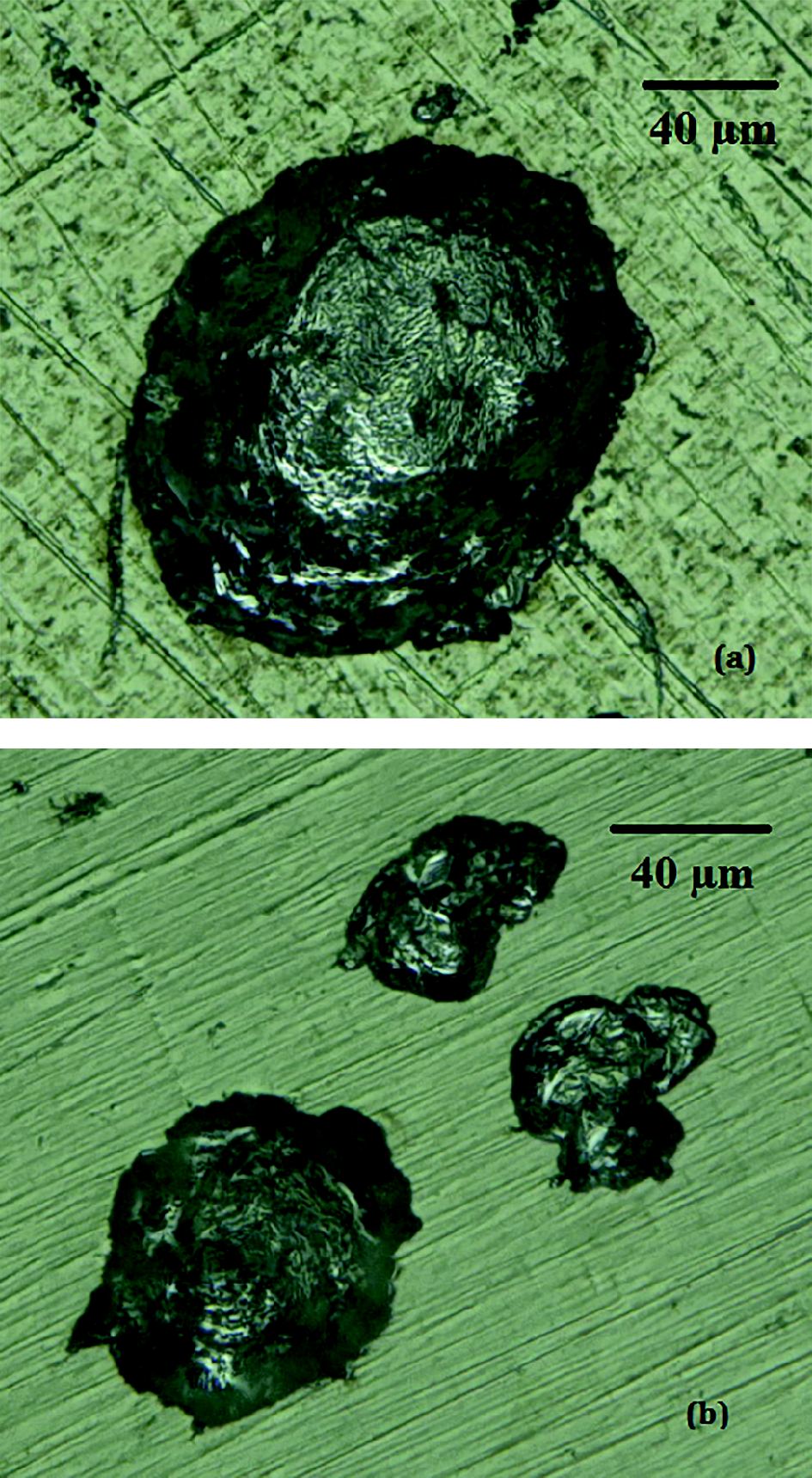
a example of single pits; b large single pit and two coalesced pits formed by overlap of two and three pits
Since the mouths of some pits especially coalesced pits were not circular in shape, pits’ mouth width measurements were performed in two directions, one along the direction with maximum width and another in the perpendicular direction to the maximum width. Figure 5 shows the graph obtained for the values of maximum pits width versus perpendicular width measured on a pitted sample. Data for single pits can be well fitted to a line with slope of 0.91 (which is close to one), indicating that the single pits were approximately circular. However, there is more scatter for coalesced pits since the pits can link together at any time during the growth period. This makes coalescence of pits a random process.
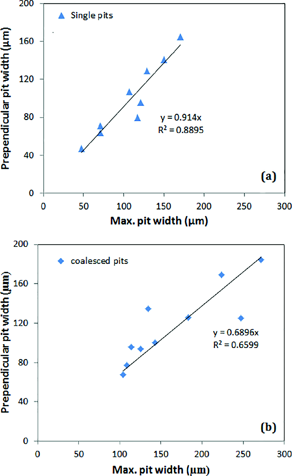
a single pits; b coalesced pits
To have also an idea about the volumetric shape of pits, depth aspect ratio, defined as ratio of pits depth to the average pit width, was measured. The aspect ratios are plotted in Fig. 6 versus pit depths. It is obvious that the aspect ratios are < 0.5 both for single and coalesced pits, indicating that the pits were not hemispherical, although the aspect ratio tended to increase towards 0.5 as the pits increased in depth.
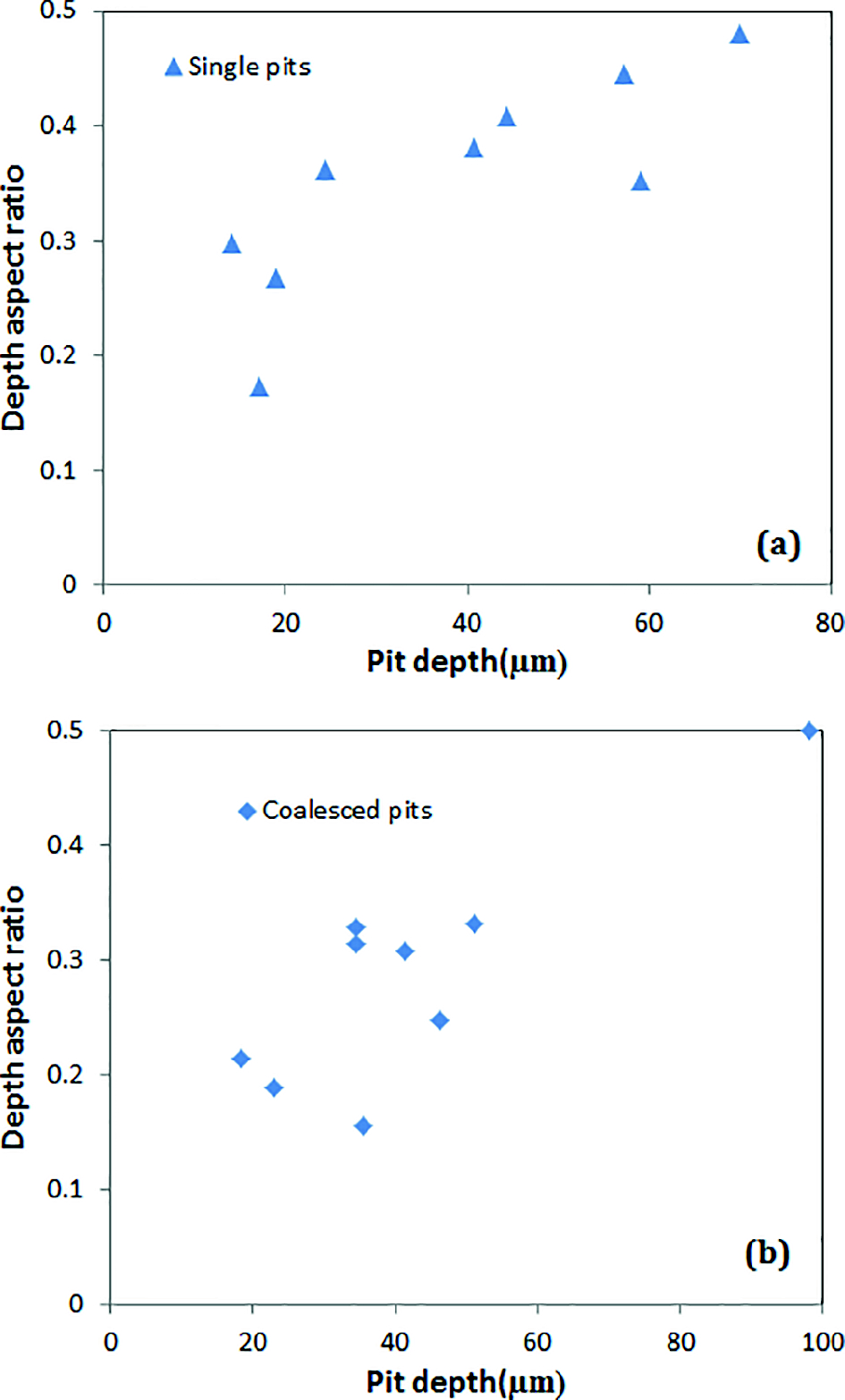
Depth aspect ratios versus measured depths for a single pits and b coalesced pits
To check reproducibility, pits were generated using the same procedure on two other specimens. The two types of pits (single and coalesced pits) were observed in all pitted specimens and slopes of the fitted lines to the graph of maximum width versus perpendicular width for single pits was obtained to be in the range of 0.85-0.94, indicating that single pits remained almost circular in all specimens. However, the slopes of the fitted lines for coalesced pits varied in a wide range of 0.35-0.76 proving coalescence of pits to be a random process with a range of possible results. It is also noteworthy that just one coalesced pit generated on the first sample had a depth aspect ratio of 0.49 (Fig. 6b), but all other coalesced pits in all tested samples had depth aspect ratios < 0.4 confirming the generation of non-hemispherical pits during 2 h of growth. If the pits were allowed to grow for a longer time, the aspect ratio would approximate 0.5, and pits would become hemispherical in shape.
Pitting mechanism
Several models have been proposed for initiation of pits on the surface of metals, but the common point in all models is adsorption of an aggressive ion like chloride on the passive surface. Based on the literature, initiation of pits in bicarbonate/carbonate solution relies on point defect model because of the observed increased donor density of passive film with adsorption of chloride ions on the film, which itself increases with increasing potential.14,15 According to the point defect model, 16 chloride ions react with oxygen vacancies and form autocatalytic cation/oxygen vacancy pairs, which propagate throughout the passive layer and reach metal substrate causing local detachment of the film, which further acts as an initiation site for pitting corrosion on the underlying metal surface. It was believed that, similar to what has been reported for stainless steels,17,18 the initiation of stable pits starts with the formation of metastable pits in micrometre sizes. This was inferred both from small current peaks observed just before transpassive potential or pitting potential in potentiodynamic curves of the solutions with 0.08 and 0.1M NaCl respectively (Fig. 3) and also from potentiostatic experiments conducted at more active potentials than pitting potential but close to it. At potentials below the pitting potential, the depth of metastable pits was insufficient to maintain an aggressive environment inside the pit for the continuous growth; however, the presence of a slat film cover over the pit mouth acts as a barrier for diffusion and dilution of the pit environment. If this cover is broken, metastable pit growth is terminated, and the pit surface will repassivate. This was observed at potentials up to 200 mV (SCE) lower than the pitting potential. Transition from metastable to stable pit growth is achieved when metastable pit has grown to a sufficient size to maintain an aggressive electrolyte inside the pit for indefinite growth. This is not achieved until the potential is raised to the pitting potential.
During pitting procedure, maintaining the potential above the pitting potential, i.e. 400 mV, allowed metastable pits to grow enough to pass the metastable growth. In the stable growth stage, the metal inside the pit will be active, and pit continues to grow. Once potential is decreased well below the pitting potential to avoid formation of new metastable pits, the rate of dissolution starts to decrease, and after some time, this rate will become lower than the rate of diffusion of metal ions outside the pit cavity; therefore, the environment inside the pit will not remain aggressive and the pit repassivates. 19 In the developed procedure, repassivation of pits took place after reaching the maximum depth of 100 μm.
Applicability of prepitting procedure for SCC studies in pipelines
Field investigations showed that 95% of crack population developed in near neutral pH environment is considered as blunt cracks and usually have a depth < 1 mm, which is equal to 10% of wall thickness for a pipe with a thickness of 10 mm. 20 It is also now believed that the growth of the other 5% sharp cracks is not continuous, and it involves intervals of dormancy (blunting) and growth, 21 so it is reasonable to conclude that the other 5% of crack population, which may lead to fracture of pipelines, has passed the dormancy stage (depth < 1 mm) at one time. Considering these cracks might have been initiated from a pit, the pits should have a depth far < 1 mm, i.e. 10% of the wall thickness, which is not considered significant from an industrial perspective, and they are not usually documented to be able to compare them with the produced pits in this paper. However, once a pipeline is failed due to propagation of cracks beyond the critical size, some information regarding field pits can be obtained by analysing regions near the fracture area, but again, since the pits observed near these cracking zones are shallow, no accurate information is available on their sizes. Figure 7 shows such pitting corrosion in near neutral environment found near the site of rupture of a buried pipeline after field service for ∼19 years. As may be seen, some cracks had been developed in the area with pits. Even though the observed pits cluster could be large in length because of overlapping of several pits, they are shallow. In the developed pitting procedure, both overlapped and single pits were generated similar to what is observed in the field, but fewer pints were generated, and they are more dispersed than observed pits in the field to avoid many interactions between the cracks that would possibly initiate from the pits in SCC tests.
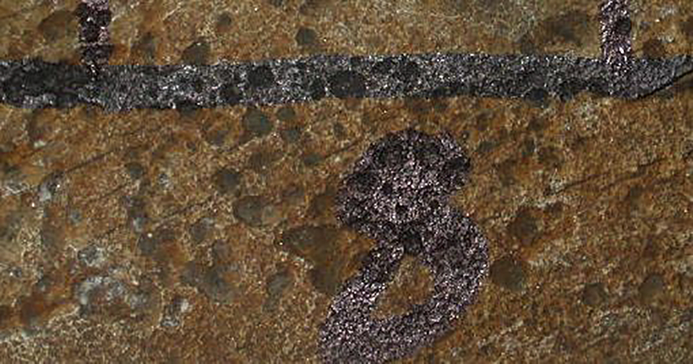
Near neutral pH pitting corrosion found near the site of rupture of buried pipeline after field service for ∼19 years
It is also well known that surfaces of pipeline steels in the field are covered with mill scale layers in spite of different surface preparation methods including shot peening used for application of coatings. It has been suggested that this mill scale causes localised corrosion and pitting due to local separation of anode and cathode sites on the steel covered by porous mill scale layer. These pits can act as initiation sites for near neutral pH SCC. 22 However, this galvanic effect was not considered in the developed prepitting procedure. Since the solution used in the prepitting procedure is believed to cause high pH SCC in the pipelines, it is possible that this procedure could simulate the real conditions to which the pipelines are exposed. However, for comparison purpose, it is a future plan to consider the galvanic effect, caused by mill scale, on the crack initiation step and to compare the initiated cracks on the prepitted samples with those initiated on a mill scaled surface.
Summary
The aim of this study was to develop a prepitting procedure for subsequent near neutral pH SCC crack initiation studies on API X-52 pipeline steel in order to accelerate crack initiation testing and also to enable investigation of pit to crack transition in a shorter period of time. It was thought beneficial to use a technique that would be as close as possible to conditions to which real pipelines could be exposed in the field. Thus, a bicarbonate–carbonate solution known to occur with high pH SCC in pipeline steels was used. Pitting procedure included initial passivation of steel in 0.5M NaHCO3+0.25M Na2CO3+0.1M NaCl solution and then an increase in the applied potential above the pitting potential to generate pits. To allow growth of generated pits and avoiding more pit generation, the potential was then decreased below the pitting potential and held until the desired pit depth of 100 μm was reached. This procedure produced a suitable density of single and coalesced pits on the surface. These pits had dept/diameter ratios less than those for hemispherical pits.
Acknowledgements
This work was supported by the National Natural Science Foundation of China (grant nos. 51131001 and 51471034) and National Basic Research Program of China (973 Program project no. 2014CB643300).