
Abstract
Cathodic electrocoatings were applied onto phosphated normal and galvanised steel substrates with average dry film thicknesses of 20 and 12 μm. To evaluate the anticorrosion properties of the coatings, electrochemical impedance spectroscopy and salt spray tests were carried out on the samples. The results showed that, by increasing the curing temperature, the protective properties of electrocoated galvanised steel are improved to a higher extent compared to normal steel panels. This was indicated by a pore resistance of two orders of magnitude higher in the case of galvanised steel panels. At lower curing temperatures, the corrosion resistance of electrocoated normal steel panels is better than that of the galvanised steel, indicated by a two orders of magnitude higher pore resistance value. On the other side, the salt spray test could not recognise the difference between protective properties of different coating films on galvanised steel suitably, and this is one of the notable disadvantages of this test.
Introduction
In the automotive industry, cathodic electrocoating is used as a corrosion protective layer, which is typically applied on normal and galvanised steel substrates in different parts of a car body simultaneously. Galvanising is an attractive and economical means of corrosion protection for a wide variety of commercial and industrial steel articles.1–4 Zinc coatings can be deposited by several methods, the most common of which is hot dip galvanising.5–7 Galvanising provides a coating of zinc–iron intermetallic alloy layers on steel with a rather pure outer layer of zinc. The zinc is anodic against steel and, thus, will provide cathodic or sacrificial protection to any small areas of steel that may be exposed to corrosive electrolytes (such as scratches and cutting edges). Also, the zinc coating will oxidise and provide a physical barrier to protect the steel surface from any direct contact with the environment. White rust is the oxide layer of zinc on the surface of galvanised steel sheet. 8
Some publications9,10 have reported that coating of a galvanised steel substrate may increase the potential for white rust. The corrosion begins on the top wet surface, and as more water collects and runs down around the cylinders, the corrosion continues, forming circumferential white stripes of corrosion product.11–14 The presence of moisture either as condensed droplets or thin layers of water on freshly prepared galvanised steel is a necessary condition for forming white rust.15–18
Liu and co-workers 19 studied the corrosion behaviour of hot dipped zinc based coatings (pure zinc, Zn–0.25Al and Zn–5Al) through potentiodynamic polarisation test and electrochemical impedance spectroscopy (EIS) in 3.5%NaCl solution. Corrosion products were analysed with SEM, energy dispersive spectroscopy and X-ray diffraction. The results revealed that Zn–5Al coating displayed the highest corrosion resistance. The corrosion product layer formed on Zn–5Al coating is more compact than the other two coatings. The β phase has two different influences on the corrosion behaviour: it can act as a galvanic cathode to hasten corrosion and act as a corrosion barrier to hinder corrosion.
Huttunen and co-workers 20 evaluated the corrosion protection of galvanised steel by polyamide coatings. They used two types of polyamide coatings (AQPI: poly (4,4’-oxydiphtalic anhydride-co-2,5-bis(4,4’-methylenedianiline)-1,4-benzoquinone) polyimides and PMPI):poly(pyromellitic dianhydride-co-4,4’- oxydianiline) polyimide in their research, and EIS and SEM tests were carried out on tested samples. Electrochemical behaviour of AQPI coated galvanised steel obeyed that of a defected coating and showed gradual decrease in its protective properties. In contrast, PMPI coating behaved like a defect free coating, and it provided the galvanised steel substrate with effective corrosion protection all through the 960 h test duration.
Park and co-workers 21 evaluated improving the anticorrosion properties of organic zinc rich coatings by incorporating surface modified zinc particles. The corrosion behaviour of zinc rich coatings with various zinc contents, ranging from 0 to 60 vol.-%, in thin organic coatings (below 5 μm) were characterised using EIS. It was corroborated that the coating containing 60 vol.-% zinc powder and that without zinc powder showed good corrosion resistance mainly because of the cathodic protection and barrier effect respectively.
There are several methods to protect the metallic structures from the corrosion. The primary means of corrosion protection for metallic structures is an organic barrier coating, which lessens the transport of water and corrosive ionic species to the substrate.22,23
Conventional means of characterising the performance of a coating's protective property is through accelerated test methods in which the time to degradation is less than that for normal aging. Test methods have been developed to simulate corrosive environmental conditions. These methods promote coating failure in shorter times compared to failure times associated with normal service conditions.24,25
Many techniques have the ability to characterise the coating substrate as well as the performance and adhesion of organic coatings.26,27 Electrochemical impedance spectroscopy has been used intensively as a laboratory based research tool for studying the performance and decline of polymeric protective coatings.28,29 The most widely used accelerated non-electrochemical test for coating evaluation is the salt spray test.30,31 The salt spray test originated in the early 1900s, and the procedure was standardised since 1939 under the name ASTM B117.31,32 It can be found in literature that little correlation exists between the results from salt spray tests and in-service performance of organic coatings. 24 Anyhow, the salt spray test is a well accepted evaluation method in the automotive industry all around the world. Garcia and co-workers 33 evaluated the effect of curing conditions on anticorrosion properties of cathodic electrodeposition (CED) that was applied on normal steel substrate using electrochemical techniques (EIS and ac/dc/ac tests). The results showed that the protective behaviour of the CED film is improved in the normal curing condition.
Lajevardi Esfahani and co-workers 34 introduced a modified ac/dc/ac accelerated test applied to cathodically electrocoated mild steel substrates baked at different conditions. This study aimed at characterising the protective behaviour of under-, normal- and over-baked electrocoatings under cyclic corrosion conditions. It was found that the resistive failure is the dominant failure mechanism of all the coatings in this test. It was also found that a low cross-link density coating withstands the mechanical stresses of dry–wet cycles better than a higher cross-link density one.
Shanmugam and co-workers 35 established manganese phosphating formulations with various additives to improve the coating weight. The aim of their investigation was to use permanganate as an additive to increase iron dissolution and to achieve subsequent improvement in the quality of manganese phosphate coating. Kinetic studies showed earlier attainment of point of incipient precipitation of manganese phosphate coating in the optimised formulation compared to other formulations under investigation.
Rastegar and co-workers 36 used two different approaches to modify an ultraviolet-curing (uv-curing) resin based on polyester chemistry, namely, molecular and nanoparticular approaches. The electrochemical properties of the coating films were investigated using EIS. In all cases, a broadening of the complex plane graph in the direction of real impedance axis was observed. Electrochemical impedance spectroscopy investigations of the UV cured films show that both molecular and nanoparticular modifications cause the electrochemical properties of the film to remain constant for a longer immersion time compared to unmodified resin.
Jamali and Mills 37 investigated the effect of thickness, curing temperature and solvent on the structural inhomogeneity of several types of organic coatings. Physicochemical tests were also employed to address the structural changes occurring because of a variation in the curing temperature and the type of solvent. Results of the physicochemical examination suggest that unreacted functional groups and water adsorption are the main causes of formation of structural defects in organic coatings.
In the present research, cathodic electrocoatings are applied on phosphated normal and galvanised steel panels at average dry film thicknesses of 12 and 20 μm and are baked in three different curing conditions. We evaluate the effect of curing conditions on the protective behaviour of the coatings applied on galvanised steel substrates and compared the results to those of normal steel panels.
Experimental
Materials
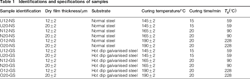
A commercial protective cathodic electrocoating material (CathoGuard 500 supplied by BASF Company, Germany) was applied on tricationic phosphated galvanised and normal steel substrates. Normal steel specimens containing 0.11C–0.012Si–0.45Mn–0.016P and hot dip galvanised steel specimens are supplied by POSCO Co. Coatings were electrodeposited for 2 min at deposition voltages of 270 ± 20 V to get 20 ± 2 μm and 190 ± 20 V to get 12 ± 2 μm dry film thicknesses. Stainless steel anodes were placed parallel to the steel panels (20 × 10 × 0.2 cm) at a distance of 19.0 cm. The temperature of the electrocoating bath was kept between 28 to 30°C. The anode/cathode area ratio was 1:3. The deposited films were then baked at three different conditions similar to under-, normal- and over-baked electrocoats. Sample identification and curing conditions are summarised in Table 1.
Identifications and specifications of samples
According to the baking window of commercial electrocoat shown in Fig. 1, the curing condition of (15 min at 145°C) is out of the baking window. On the other hand, the normal and overbaking conditions in this research are in the baking window of commercial electrocoat.
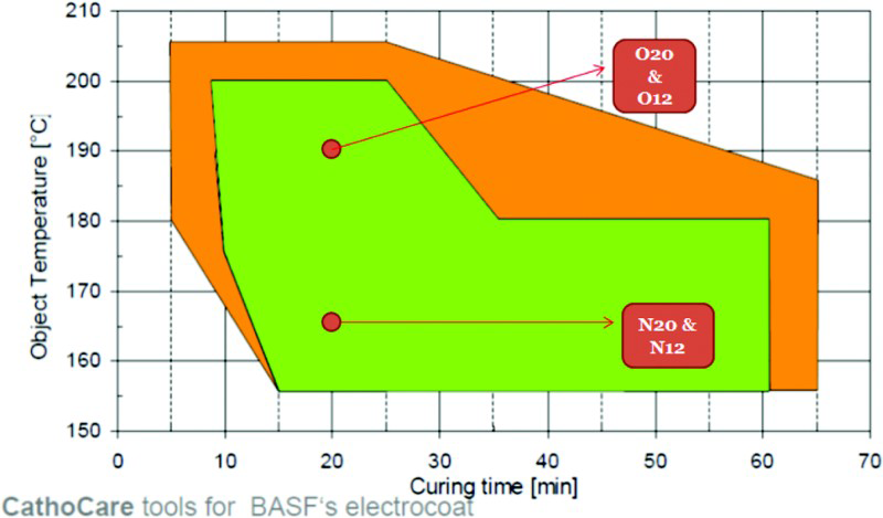
Baking window of commercial BASF electrocoat 38
Any test on all 12 types of samples was repeated three times, and the average results have been reported.
Testing methods and equipment
Differential scanning calorimetry (DSC)
A Perkin Elmer DSC7 differential scanning calorimeter was used for dynamic scans to measure the glass transition temperature (Tg) of electrocoatings cured at different conditions. The average weight of samples was 6 mg, and DSC scans were performed at a rate of 10°C min to determine the midpoint (Tg).
Electrochemical impedance spectroscopy
To run the EIS test, the surface of electrocoated samples (except for samples U-NS and U-GS because these films were not fully cured and may dissolve in the solvent) was cleaned by isopropyl alcohol. After that, a 1 cm2 of the surface of electrocoated samples was considered, and the rest of the parts were sealed by beeswax and rosin mixture. Electrochemical impedance spectroscopy tests were carried out on coated samples exposed to 3.5% (w/w) NaCl solution in deionised water. A three electrode electrochemical cell set-up was used. The exposed surface area was 1.0 cm2. A graphite rod was used as the counter electrode, and an Ag/AgCl electrode was used as the reference electrode with a KCl concentration of 3.5M. The impedance tests were carried out over a frequency range of 100 kHz down to 1 mHz using a sinusoidal perturbation voltage of 10 mV from peak to peak. The whole set-up was placed inside a Faraday cage to reduce external interferences on the system. Electrochemical impedance spectroscopy test was carried out under open circuit conditions. The impedance spectrum was analysed using Z-view software. Fitting the EIS data will settle values of the equivalent circuit elements. The chi squared limit of the fitting was usually below 0.1. In addition, the impedance parameters have been normalised to the surface area of the samples.
Salt spray test
To run the salt spray test, the surface of electrocoated samples (except for samples U12-NS, U20-NS, U12-GS and U20-GS because these films were not fully covered and may dissolve in the solvent) was cleaned by isopropyl alcohol. After that, the electrocoated samples on normal steel were scratched according to the PSA D171058 test method. The electrocoated galvanised steel were not scratched. The sample panels were then placed into the salt spray chamber. The duration of this test was 1000 h due to the PSA D171058 test method. Each day, the sample panels were checked out, and the rate of corrosion on them was evaluated visually. After 1000 h, the sample panels were removed from the salt spray cabinet, and the creepage and degradation of the unscratched area were explored according to ASTM D1654.
Gravimetric test
The surface of electrocoated samples, except for under-baked samples, was cleaned by isopropyl alcohol.
Then an area of 1 cm2 from the surface of each electrocoated sample was selected, and the rest of the sample was fully covered with beeswax/rosin mixture. The initial weight of each sample was measured with an accuracy of 0.1 mg before immersing them into a solution of 3.5% (w/w) NaCl in deionised water for 7 days (soaking step). Then, the samples were weighed again and afterwards were placed in a desiccator for 24 h (dry step). After the dry step, the weight of the samples was measured again. This process lasted for 20 days. The time program of the gravimetric test during the soaking and dry steps is shown schematically in Fig. 2.
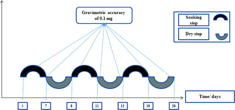
Time program of gravimetric test during soaking and dry steps
Results and discussion
Differential scanning calorimetry thermogram
The glass transition temperature (Tg) of the electrocoated samples, obtained from the DSC measurements, are listed in Table 1.
According to the DSC results, the (Tg) of the under-baked samples is less than that of the other samples because of its incomplete curing and lower final cross-linking density. Existence of a bigger curing peak in the DSC thermogram of the over-baked sample shows more released blocked isocyanate groups, and more reactions with hydroxyl groups resulted in complete curing of the over-baked sample compared to the other samples. The network of the binder in the under-baked sample should have a high free volume content. There is only a slight difference between the (Tg) value of the under-baked samples and room temperature (23 ± 2°C), so the under-baked samples are expected to be more flexible than the other samples. The DSC results of the over- and normal-baked samples imply that the final cross-linking density of these samples is high enough. Therefore, the over- and normal-baked samples are expected to be more cross-linked and less flexible.
Electrochemical impedance spectroscopy test results
The variations of pore resistance and coating capacitance of the electrocoated samples are shown in Fig. 3.
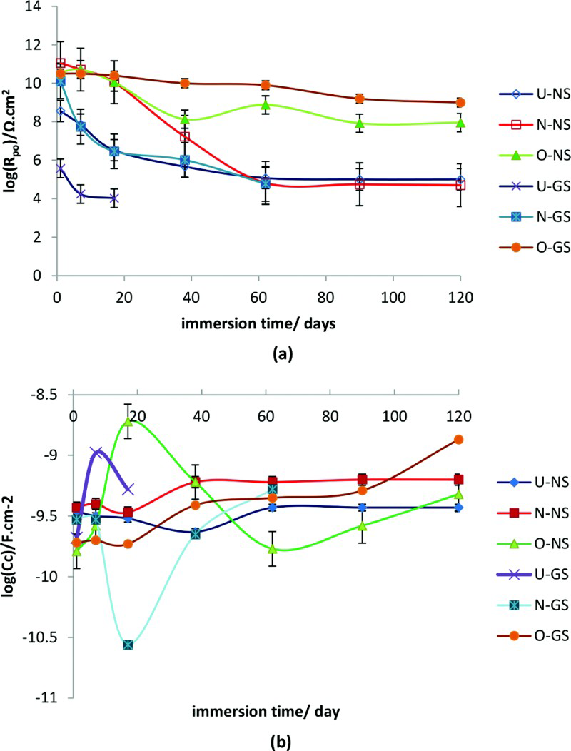
a pore resistance variations of electrocoated samples during time of immersion and b coating capacitance variations of electrocoated samples during time of immersion
Fig. 4 shows the equivalent circuit parameter (from the Randle and the Mansfeld models), which corresponds to pore resistance R po after 1 and 17 days of immersion for electrocoated samples.
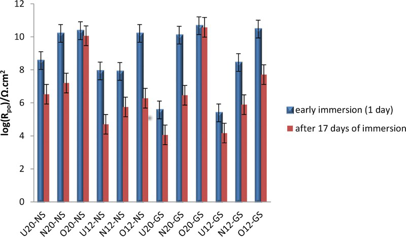
Comparison of pore resistance variations of different electrocoated samples at EIS test
According to the results in Fig. 3, the pore resistance of the sample (U-NS) is about four orders of magnitude more than the sample (U-GS) after 7 days of immersion. On the other side, the corrosion takes place at the metal/coating interface after 60 days of immersion (R po decreasing is about five orders) for both of the samples (N-NS) and (N-GS). The results of the EIS test for the over-baked samples showed that the pore resistance of the sample (O-NS) was dropped about two orders after 120 days of immersion. On the other hand, for sample (O-GS), the extent of pore resistance was declined about one order after 120 days. During the immersion of the samples in 3.5%NaCl solution, water and corrosive ions migrate to the electrocoating film gradually, causing corrosion reactions at the metal/coating interface. In addition, the electrochemical failure of the under-baked samples (U-NS) and (U-GS) is more compared to the other samples probably because of more free volume excitation at their electrocoating films. For the under-baked electrocoated samples, the degradation time and amount of pore resistance failure of the sample (U-GS) are less compared to the sample (U-NS). It can be understood from the results that, by increasing the curing temperature, the protective properties of the electrocoated galvanised steel are improved, but at low curing temperatures, the protective properties of the electrocoated normal steel sample are better. The reason for this fact might be assigned to the different behaviours of the galvanised steel and normal steel substrates at curing conditions. The thermal conductivity of normal steel is ∼2.5 times more than the thermal conductivity of galvanised steel. On the other side, the thermal expansion coefficient of the galvanised steel is about three times more than normal steel (thermal conductivity of normal steel and galvanised steel is ∼45 and 18 W m− 1 °C− 1, and the thermal expansion coefficients of normal steel and galvanised steel are ∼6.7 and 19.3 ppm °C− 1 respectively).39–41
Because of the lower thermal conductivity of galvanised steel than the normal steel, the heat transfer to the electrocoating film occurs slower resulting in a lower baking of the film compared to the electrocoated film on normal steel at the same curing conditions. According to the baking window of commercial electrocoat, 38 the curing condition of 15 min at 145°C is out of the baking window, so the electrocoating that was applied on both the substrates (normal and galvanised steel) is under-baked. Owing to the lower thermal conductivity of the galvanised steel than the normal steel, the degree of curing of the electrocoat applied on the galvanised steel is less than the electrocoat applied on normal steel. On the other hand, the normal and overbaking conditions in this research are in the baking window of the commercial electrocoat. In other words, at normal and overbaking conditions, the baking time and temperature are enough for complete baking of the electrocoat especially at overbaking conditions. Therefore, the electrocoated films that were applied on normal and galvanised steel cured at overbaking conditions are completely cured, and because of the better anticorrosive properties of bare galvanised steel, the protective behaviour of the electrocoated galvanised steel is better than the electrocoated normal steel panel. Because of the presence of the different zinc layers on the steel surface in the galvanised steel panels and the fact that the thermal expansion of galvanised steel is ∼3.5 times more than normal steel, higher extents of mechanical stresses can be developed under the coating films applied on the galvanised steel. This will finally result in more expanded and more stressed films and film/substrate interfaces and loss of adhesion to the substrate. The thermal expansion coefficient of typical epoxy resins used in protective coatings is more than that of the steel substrates. 41 This may result in more expansion of the electrocoated film and enhanced mechanical stresses under the coating film. The results of this research confirmed that the anticorrosion properties of fully cured electrocoated galvanised steel are better than those of electrocoated normal steel substrate. According to the EIS results (Fig. 2), the pore resistance parameter of under-baked samples at the beginning of immersion was less than others because of their lower cross-linking density. The samples cured at a higher temperature (190°C) show a slower descending trend after 17 days of immersion. This means the over-baked coating shows better anticorrosive properties compared to under- and normal-baked samples.
Results of the gravimetric test during soaking and drying cycles are shown in Fig. 5.
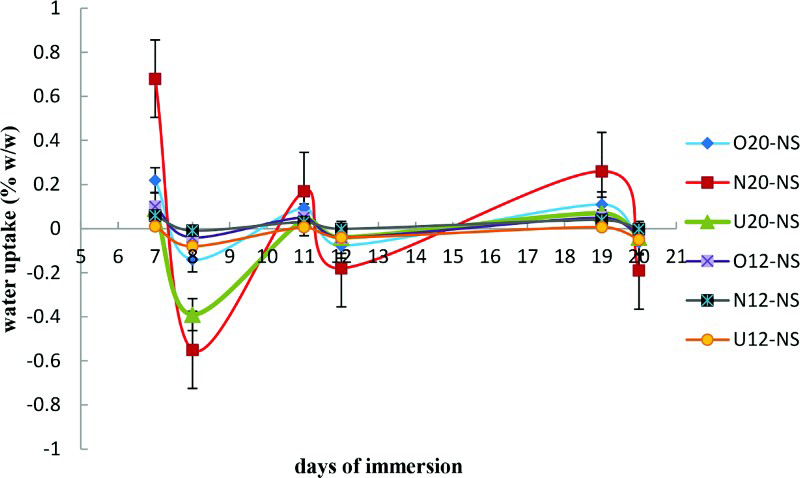
Absorption and excretion of water during soaking and dry steps of gravimetric test
As specified in Fig. 5, all the electrocoatings absorbed water during immersion in the 3.5% (w/w) solution of NaCl in deionised water, and throughout drying in the desiccator, almost all the absorbed water in the electrocoating film was removed, and the film was dried completely.
The oscillation amplitude of absorption and excretion of water for normal-baked samples is more than other samples. According to the results of the EIS test in early immersion before DC application, the initial pore resistance of the under-baked electrocoatings was lower than the other samples. Moreover, according to the results of the DSC test, the glass transition temperature of the under-baked samples undertakes the lowest value among all the samples. Because of the high porosity of the under-baked samples, it can be assumed that the electrocoated film acts as a permeable membrane against the electrolyte absorption and desorption, resulting in simultaneously easy absorption and desorption of water. On the other side, due to less porosity, the normal-baked samples have a balanced absorption and excretion of water during the soaking and drying steps, which may be the reason why the remaining water in free volume of the normal-baked electrocoating films is the largest. Probably because of less pores, it is not possible for the water to completely leave the electrocoated film during the drying cycles.
Salt spray test results
The images of the scratched electrocoated normal steel samples are shown in Fig. 6 before and after the salt spray test (1000 h).
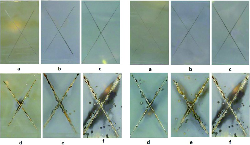
Left side set: images of 20 μm electrocoated samples on normal steel (a O20-NS/before salt spray test, b N20-NS/before salt spray test, c U20-NS/before salt spray test, d O20-NS/after 1000 h exposure in salt spray chamber, e N20-NS/after 1000 h exposure in salt spray chamber and f U20-NS/after 1000 h exposure in salt spray chamber); right side set: images of 12 μm electrocoated samples on normal steel (a O12-NS/before salt spray test, b N12-NS/before salt spray test, c U12-NS/before salt spray test, d O12-NS/after 1000 h exposure in salt spray chamber, e N12-NS/after 1000 h exposure in salt spray chamber and f U12-NS/after 1000 h exposure in salt spray chamber)
The results of salt spray test according to ASTM D1654 are shown in Table 2.
Results of salt spray test according to ASTM D1654 (rating scale = 10 belongs to minimum failure, rating scale = 0 belongs to maximum failure)
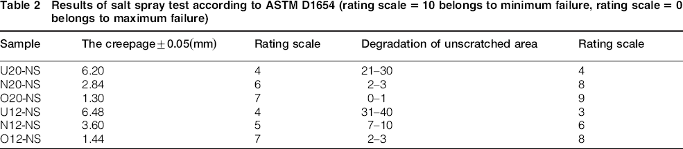
When the curing temperature is low (145°C), the curing reactions occurred slowly, so the final cross-linking density is not high enough. The network of the binder will have a high free volume content that will allow the ions and reactive species to reach the interface, causing corrosion reactions at the metal/coating interface and probable delamination of the coating. According to the salt spray test results, the creepage at the scratched area and degradation of the unscratched area in the form of blisters for sample U12-NS were more than those of the other samples. Otherwise, the salt spray test result of the over-baked samples showed that the protective properties of these samples were better than the others. The results showed that by increasing the thickness of the electrocoating film, the protective behaviour of the coating is improved because of the stronger barrier effect of the coating against diffusion of water and corrosive ions into the coating film.
The images of the electrocoated samples on the galvanised steel are shown in Fig. 7 before and after salt spray exposure (1000 h).
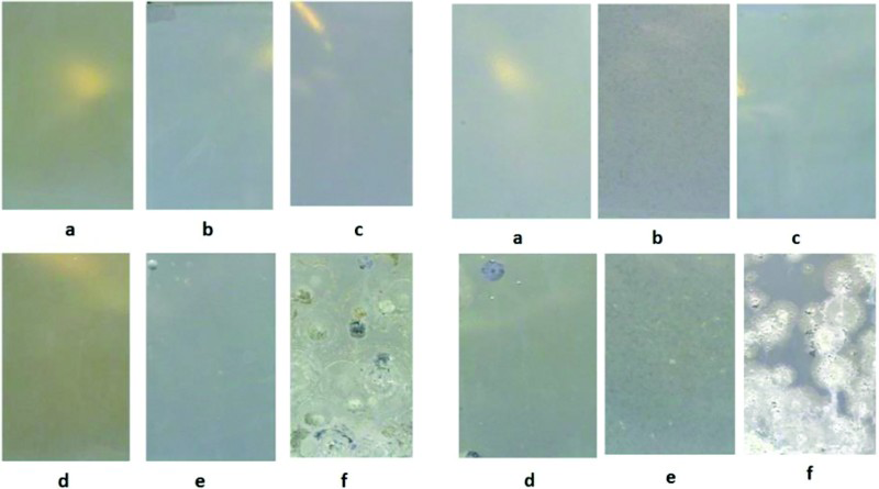
Left side set: images of 20 μm electrocoated samples on galvanised steel (a O20-GS/before salt spray test, b N20-GS/before salt spray test, c U20-GS/before salt spray test, d O20-GS/after 1000 h exposure in salt spray chamber, e N20-GS/after 1000 h exposure in salt spray chamber and f U20-GS/after 1000 h exposure in salt spray chamber); right side set: images of 12 μm electrocoated samples on galvanised steel (a O12-GS/before salt spray test, b N12-GS/before salt spray test, c U12-GS/before salt spray test, d O12-GS/after 1000 h exposure in salt spray chamber, e N12-GS/after 1000 h exposure in salt spray chamber and f U12-GS/after 1000 h exposure in salt spray chamber)
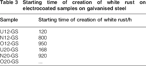
The electrocoated samples on galvanised steel were visually evaluated every 24 h during 1000 h of salt spray test to recognise the starting time of creation of the white rust on the panels. The results of this investigation are shown in Table 3.
Starting time of creation of white rust on electrocoated samples on galvanised steel
According to the results in Fig. 6, the protective properties of the under-baked samples failed sooner than the others, but as mentioned, there is no possibility for complete and correct comparison between the results of the anticorrosion properties of the electrocoated samples on galvanised steel at various conditions. On the other hand, according to the salt spray test results, there is no significant difference between the results of (O20-GS) and (O12-GS) and for the normal- and under-baked samples, too. This is one of the disadvantages of the salt spray test as a non-electrochemical test, which is not able to disclose the protective behaviour of the coatings on galvanised steel. In a continuous salt spray fog test, the samples do not experience any wet/dry cycle, which is critical in the performing hot dip galvanised steel because the zinc carbonate is not able to form on the galvanised coating. If the zinc carbonate does not form, an accurate prediction of the real performance of the coated hot dip galvanised steel is not possible. In other words, the salt spray test attacks the wrong material (zinc metal instead of the zinc carbonate) and, therefore, will give an incorrect prediction of the performance of the hot dip galvanised coating in the outdoor conditions. 41
According to the results, it can be found that the EIS technique, as a powerful tool for characterisation of the protective behaviour of a coating film, is able to analyse the details of the anticorrosion properties of the different CED films after 17 days of immersion. Furthermore, the salt spray test as a common non-electrochemical test in automotive industry could not characterise the difference between the protective properties of the different CED films on galvanised steel after 1000 h of exposure properly, and this is one of the notable disadvantages of this test.
Conclusions
In this research, cathodic electrocoatings were applied on phosphated normal and galvanised steel substrates with average dry film thicknesses of 20 and 12 μm and cured in three different conditions. To study the protective behaviour, EIS and salt spray tests were carried out on the samples. The EIS test results showed that by increasing the curing temperature, the protective properties of electrocoated galvanised steel are improved at a higher extent compared to the electrocoated normal steel panels. But at low curing temperatures, the protective properties of the electrocoated normal steel panels are better. According to the salt spray test results of the electrocoated samples on the normal steel substrate, the creepage at the scratched area and degradation of the unscratched area in the form of blisters for under-baked samples were more than those of the other samples. Therefore, good correlation can be observed between the results of the electrochemical test and a non-electrochemical test for electrocoated normal steel samples. On the other side, the salt spray test as a non-electrochemical and common test in automotive industry could not characterise the difference between the protective properties of the different CED films on galvanised steel after 1000 h of exposure properly.
Footnotes
Acknowledgements
The authors gratefully acknowledge the support of Irankhodro automotive manufacturing Co.