
Abstract
This paper reviews five field assessments of the cathodic protection of coated steel pipelines buried in soils of an average resistivity of 4300 Ω cm, performed using the close interval survey (CIS) technique and incorporating the instant off potential (IOP) method to measure any voltage drop. Multiple current sources were identified in the surveys, and simultaneous interruption of all the current sources was achieved using synchronised switches. The results presented here highlight the importance of incorporating the IOP method when performing CIS in order to quantify the voltage drop factor and thus improve the interpretation of potential measurements. Unexpected field situations encountered when performing the CIS technique are discussed and the practicality of using corrosion coupons is analysed.
Introduction
Cathodic protection (CP) is based on the ability of an external impressed current source or a galvanic current supplied by an anode to polarise a metal towards a more active (negative) value at which its corrosion rate is acceptably low,1–3 the anodic reaction is suppressed (Fe → Fe2++2e− ), and the cathodic reaction is enhanced (O2+2H2O+4e− → 4OH− or 2H++2e− → H2).
The potential of a buried pipeline at a given location is commonly referred to as the pipe to soil potential. This magnitude is measured between the pipeline and a reference electrode, typically a copper/copper sulphate electrode (CSE) inserted in the soil directly over the pipe. When CP is operating, it is known as the potential on, and when CP is switched off, it is referred to as the potential off.
Voltage drop IR Ω is an inherent difficulty in CP measurements. This factor is unrelated to the actual pipeline to reference cell (CSE) voltage and is due mainly to ohmic resistance, which is a function of the soil resistivity ρS and/or metal resistivity, the experimental cell geometry, the path's cross-sectional area, the distance between the pipeline and the CSE electrode and the magnitude of the current flows. The magnitude of the voltage drop and its effect on the potential on of a buried or submerged pipeline can be measured using the instant off potential (IOP) method.
Instant off potential
The IOP is the polarised half cell potential of an electrode measured immediately after the CP current iCP is switched off and before any appreciable depolarisation has occurred. This reading closely approximates the potential without IR Ω. All current sources affecting the pipeline have to be simultaneously switched off, and the iCP must go to zero at the moment of the measure. The measured value indicates the polarised potential (potential on) of the pipeline. Combining the IOP method with global positioning system technology allows a zero iCP to be attained with greater confidence.
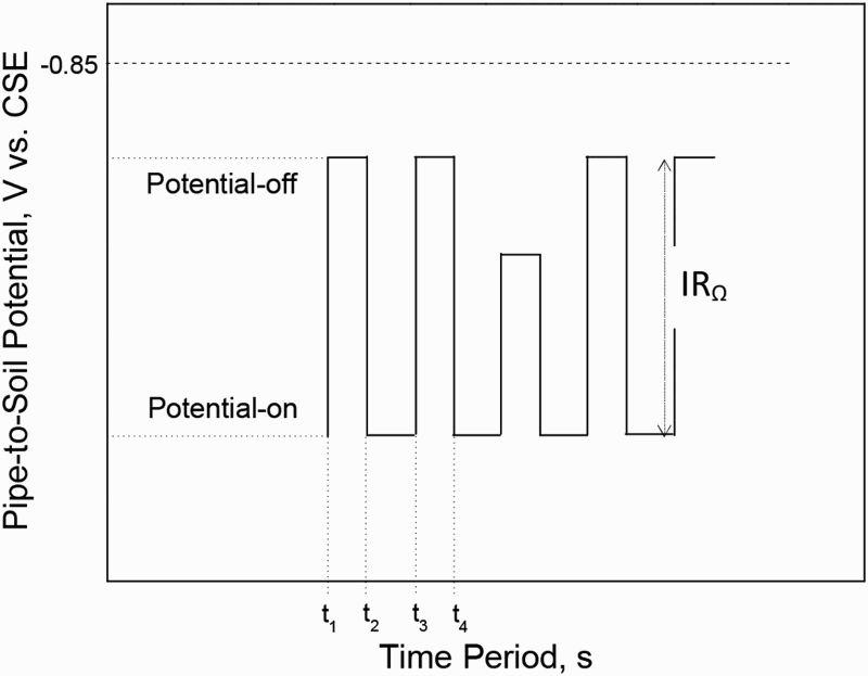
Measurement of the voltage drop using the IOP method is based on the simple application of Ohm's law. Figure 1 (inset) shows the electrical equivalent circuit (EEC) (Randles model) used to describe the application of IOP for the pipe/soil system, and Fig. 1 shows its response. When the current I flows through the EEC, the voltage drop across the resistor R Ω is IR Ω, and the voltage drop across the resistor R P is IR P. If the flow of this current is suddenly interrupted, I goes to zero and the voltage across R Ω drops very quickly, but the voltage across R P drops slowly due to the presence of the capacitor C DL associated to the electrochemical double layer (DL) with a finite charging time.
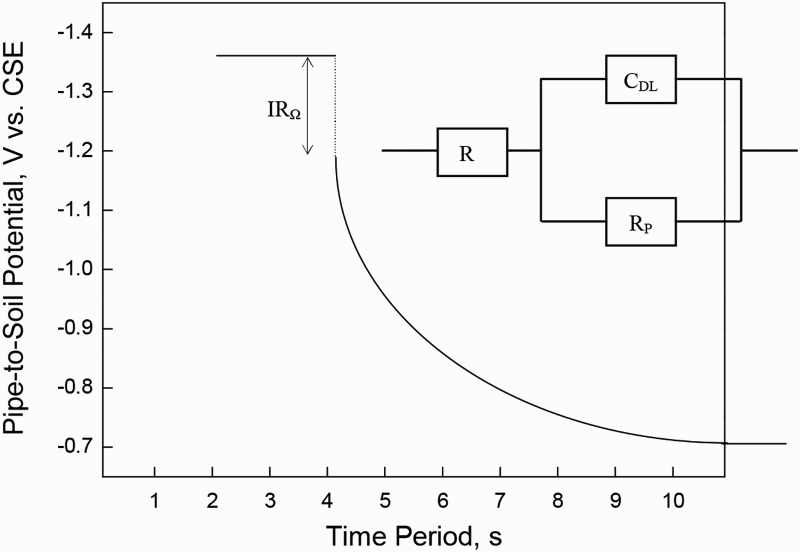
Pipe to soil potential versus time from interrupt to voltage drop IR Ω measured by IOP method for a pipe/soil system. Inset: EEC (Randles model) constituted by parallel R PC DL, where R P is the polarisation resistance and C DL is the electrochemical DL, in series with R Ω, electrolyte resistance
An electrochemical interface (pipe/soil system) is constituted by passive electrical elements such as resistors and capacitors. Capacitors are sometimes described as constant phase elements (in S sn cm− 2), distributed over the surface of the electrode, where n represents factors related with the distribution of the constant phase element parameter, such as the roughness of the electrode surface. 4 The polarisation resistance R P determines the kinetics of the reaction (corrosion) taking place at the interface. 5
The impedance Z of the Randles model (Fig. 1 inset) is given by


Equation (2) can be evolved with Thaler's series
6

The effectiveness of the IOP method to measure IR Ω can only be determined indirectly: (i) by confirming the interruption of CP of all the current sources applied, (ii) by measuring lateral potentials and (iii) by measuring the metal IR Ω drop. 8
Given that IOP is measured by cyclical disconnection of all the sources affecting the surveyed area and recording the potential at that instant, IOP presents significant limitations if there are unknown current sources such as alternating current (AC) interferences, stray currents or recirculation currents. Pipelines may be under AC interferences if they are close to high voltage AC power transmission lines and/or AC powered rail transit systems.9,10
Others ways to measure IR Ω are as follows: (i) with the CSE as close as practical to the pipeline; (ii) placing the CSE at a remote location; (iii) decreasing the current in steps while measuring potential shifts in the pipeline with respect to the soil and the voltage gradient at the surface; or (iv) the use of corrosion coupons.8,11
Figure 2 shows a typical potential versus reference point profile for an epoxy coated API carbon steel pipeline at a pipe cover depth of ∼1.5 m and a ρS of 15 × 103 Ω cm (high resistivity), which was assumed to be uniform. The distance between reference points was 100 m, and the pipeline service age was 9 years. The transformer/rectifier unit used had an output capability of 4.9 V and 0.4 A. As can be seen, the potential on readings includes an extremely high IR Ω (∼2.0 V), which may lead to erroneous interpretation of the effectiveness of the applied CP system. Attention is drawn to reference point 4 ( − 0.907 V versus CSE) because of the closeness of its potential off to the protection criterion of a CP voltage of − 0.85 V versus. CSE.
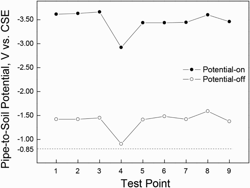
Pipe to soil potential versus reference points along pipeline in pipe/soil system with service age of 9 years, measured using IOP method. Distance between points, 100 m
These results are typical of arid zones or similar, where low humidity and a lack of saline components in the earth lead to the formation of a very limited electrolyte film on the pipe surface.
Figure 3 shows a typical potential versus reference point profile for an epoxy coated API carbon steel pipeline at a pipe cover depth of ∼1.5 m and a ρS of 4300 Ω cm, which was assumed to be uniform. The distance between reference points was 100 m, and the pipeline service age was 7 years. The results shown in this figure correspond to the entire 7-year period. As can be seen, false assumptions may be made if the IR Ω value (∼0.6 V) is not taken into account. For instance, reference points 1 and 3 may be interpreted erroneously as being protected. This example emphasises the practical importance of quantifying the IR Ω factor value in order to assure a valid interpretation of a potential on reading.
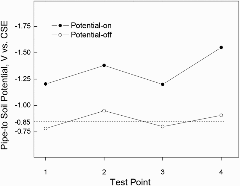
Pipe to soil potential versus reference points along pipeline in pipe/soil system with service age of 7 years, measured using IOP method. Distance between points, 100 m
Close interval survey
Close interval survey (CIS) is a close interval potential survey. The maintenance of a CP system (impressed or galvanic current) usually includes recording potential measurements at test stations and risers on an annual basis. The assumption is that if the measurements at the test stations and risers meet the protection criteria for effective CP, the points in between should also comply. The CIS method can be used to determine whether all the points along a pipeline really meet these criteria. Most commonly, potential readings are recorded at 30 cm or 1 m intervals.8,11
Another type of survey commonly used is that of direct current voltage gradient or AC voltage gradient surveys, which are used to detect coating defects. This type of survey consists of the application of a DC or an AC signal to the underground pipeline and the use of a CSE cell measurement to locate any coating defect. It can also classify the size of coating defects. These surveys can help to find mechanical damage on pipes that have been hit by a back digger or buried fittings such as flanges.
The aim of this paper is to evaluate the use of CIS incorporating the IOP method to determine the effectiveness of CP systems applied on buried pipelines. The advantages of this combined methodology are discussed, and its utility has been corroborated for a cathodically protected pipeline by reference to five case studies.
Case studies and discussion
Five case studies involving the use of CIS in conjunction with IOP methodologies for a cathodically protected pipeline have been considered. There follows a discussion of the limitations encountered and the proposal of suggestions for their solution.
Valve pit with two dielectric gaskets
This study considers a 61 cm (24 inch) diameter standard 40 API 5L PSL − 1 X52 carbon steel pipeline with a coal tar epoxy coating in a soil of an average ρS of 4300 Ω cm, which was assumed to be uniform. The working fluid was a diesel fuel and the working pressure was 1800 kPa, in an ambient temperature of 3-40°C. The distance between two references points was 100 m, and the pipeline service age was 35 years. The objective was to find an explanation for the apparently anomalous recorded potentials.
Figure 4 shows a typical potential versus reference point profile for this piping. As can be seen, the recorded potential meets the protection criterion ( − 0.85 V versus CSE). However, reference points 4 to 7 are well below this criterion. Use of the CIS technique in conjunction with the IOPIOP method led to the discovery of excessively low potentials (perhaps only the native potential). Subsequent excavation of the pipeline revealed an unknown underground valve pit with two dielectric gaskets in place. The dielectric gaskets installed on the pipeline at either end of the underground pit had broken the electrical continuity.
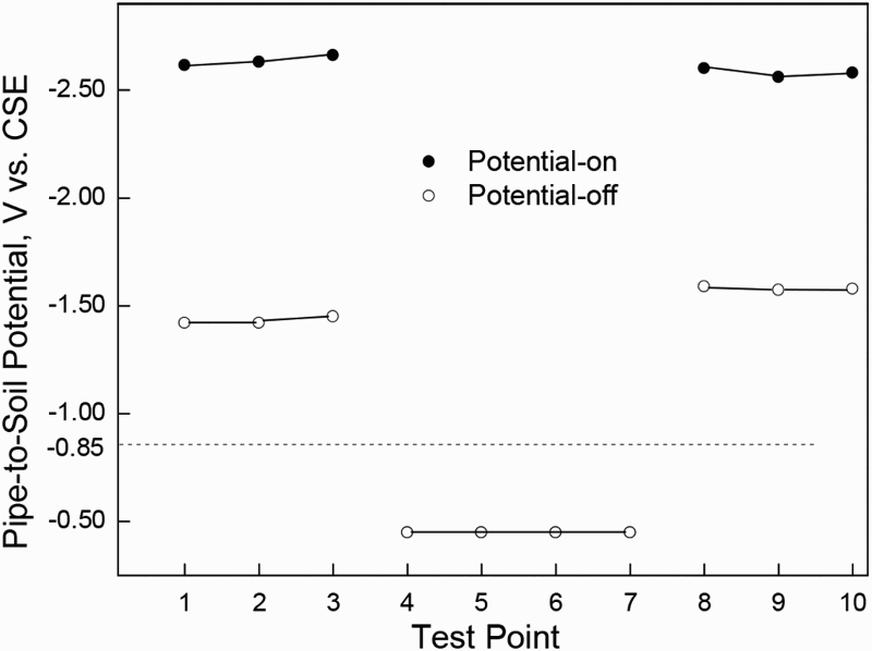
Pipe to soil potential versus reference points along pipeline incorporating valve pit with two dielectric gaskets, measured using IOP method. Distance between points 1 and 10, 100 m
Pipe crossing road
The surveyed pipe was a 25.4 cm (10 inch) diameter seamless standard 40 API spec 5L grade B carbon steel with a DIN 30670 coating system of factory applied adhesive undercoat and continuously extruded plastic resin. The ρS was 4300 Ω cm and was assumed to be uniform. The working fluid was a kerosene base fuel, and the working pressure was 1800 kPa. The ambient temperature was 3-40°C. The distance between reference points was 10 m, and the service age of the pipeline was 10 years.
Figure 5 shows a typical potential profile measured along the pipeline using the CIS methodology and how the potentials dropped as the surveyors approached locations where the pipe crossed a road (indicated by the arrows). Potential on measurements was recorded using a Fluke voltmeter and a freshly charged M.C. Miller Model RE-5 CSE reference cell. To obtain IOP measurements, synchronised current interrupters built into the rectifiers were used with a cycle of 30 s on and 3 s off. The carrier pipe was not shorted to the pipe casing. The pipeline was correctly installed inside the pipe casing, avoiding direct contact with the casing, as shown in the inset of Fig. 5.
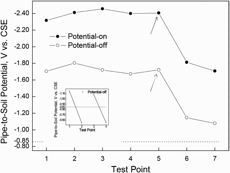
Pipe to soil potential versus reference points along pipeline at road crossing, measured using IOP method. Distance between test points, 10 m. Inset: pipe to soil potential versus reference points inside pipe casing at road crossing, measured using IOP method. Distance between test points, 10 m
After finding these potential on readings, both ends of the pipe casing were excavated and exposed to the natural environment. When the ends of the pipe casing were exposed, the sealing boots were removed and hundreds of litres of water mixed with fuel rushed out. Water in pipe casings can cause corrosion on the carrier pipe within the casing, and the CP system has no effect on the pipe inside the pipe casing because the casing blocks the protective current. In this case, leakage of the transported fuel in the soil at pipe depth had occasioned pollution of the natural environment.
Figure 6 shows an alternative solution to the original CP design, consisting of CP of the carrier pipe by means of a sacrificial magnesium anode, which may be installed inside the pipe casing along with proper sealing boots. The calculation of the amount of sacrificial anode required to protect the pipe for its projected life was as follows.12,13
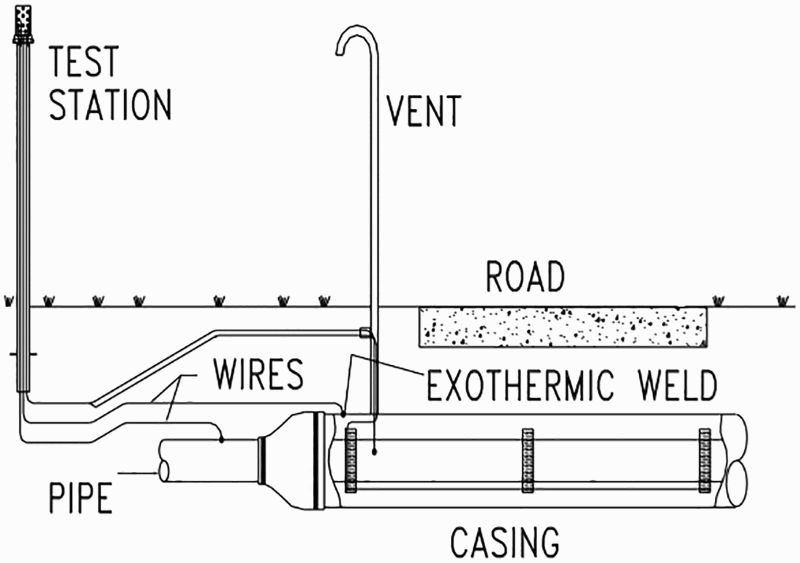
Layout of buried pipeline system under road with casing for CP system
Assuming that when an i CP is applied to a pipeline, most of the voltage drop is caused by the coating and not the soil, the specific resistance of the coating R REV (in Ω m2) can be used to calculate the required current per unit surface area. In this case, reference is made to the criterion of a minimum cathodic voltage shift of 300 mV produced by the application of protective currents

Average specific resistance of coating R REV on long pipeline with minor ramifications 14
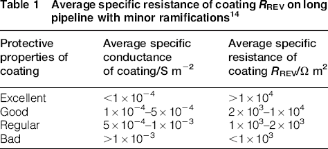
For a coating with good protective properties, having a surface area S of 1 m2 and a soil resistivity ρS of 1000 Ω cm, the i CP required to produce a polarisation decay measurement of 0.3 V is i CP = 0.3/2 × 103 = 0.15 × 10− 4 A/m2 = 15 mA/m2.
As the actual soil resistivity is 4300 Ω cm, it is usual to linearly extrapolate the specific resistance to this value, obtaining for the R REV parameter: R REV = 2 × 10³(4300/1000) = 2 × 103 × 4.3 = 8.6 × 10³ Ω m2. Therefore the required i CP was i CP = 0.3/8.6 × 103 = 34.88 mA/m2.
The electrochemical capacitance C P is given by the expression C P = i CP × H (in A year), where i CP was as defined above and H is the projected anode life (20 years). Assuming a pipeline of length L of 10 m and diameter D of 0.254 m, the surface area of the pipeline was S = πDL = π × 0.254 × 10 = 7.98 m2. As calculated above, the i CP was 34.88 mA m− 2.Thus, i CP = 34.88 mA/m2 × 7.98 m2 = 0.278 A. Finally, C p = 0.278 × 20 = 5.56 A year.
The minimum anode weight W was calculated using the expression

For a magnesium anode, C a is 0.250 A year kg− 1, U is 0.85 and if E is 50%, as suggested by the standards.8,11 The minimum weight of a magnesium anode was W = 5.56/0.250 × 0.85 × 0.5 = 52.3 kg.
Two bonded pipes without potential measurements
Figure 7 shows the potential response of the IOP method when not all the current sources applied have been switched off for an epoxy coated API carbon steel piping at a pipe cover depth of ∼1.5 m and a ρS of 4300 Ω cm, which was assumed to be uniform. The distance between reference points was 100 m, according to the standards,8,11 and the pipeline service age was 10 years. As can be seen, the third step is the most electronegative, there being a significant rise in the potential of the pipe, which should not have been present. This issue was due to an unknown cathodically protected pipeline belonging to an external system that could not be switched off.
Pipe to soil potential versus time for system where not all applied current sources have been switched off, measured using IOP method
The absence of control of the pipeline polarisation level can be problematic, especially if the pipeline is built of aluminium. Aluminium, lead and zinc are amphoteric metals and are liable to experience corrosion in high pH conditions. For an amphoteric metal the maximum potential with IR Ω compensation is − 1.20 V versus CSE. In this situation and as a hypothesis, the installation of a corrosion coupon attached to the protected pipeline close to where the potential readings were more electronegative may be a good alternative for evaluating the CP effectiveness, because the presence of an external current does not alter the coupon reading. 15
By disconnecting the corrosion coupon from the pipe, and therefore also from the CP system, and measuring the potential of the coupon (corrosion potential E corr) using a CSE placed very close to the coupon or in a soil access tube, IOP errors for the coupon are either eliminated or minimised.
Corrosion effect of interaction of stray currents
A number of factors affect the kinetics of corrosion processes on the external surfaces of metallic structures containing aggressive media. One of these is the current interference, e.g. the interaction of stray currents.
Figure 8 shows the pattern of a stray current on an underground pipeline that intercepts the CP gradient, a change in the voltage with respect to distance (in mV m− 1). A indicates the reference points on the underground pipeline, and B represents the crossing point with another pipeline.
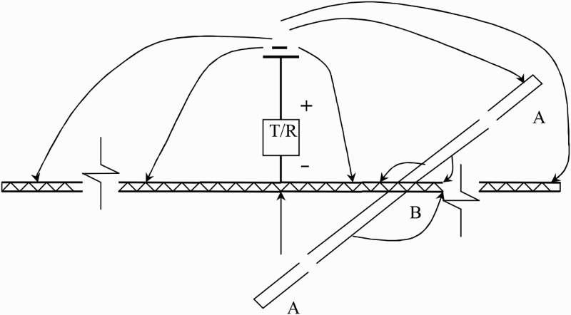
Layout of stray current from unrelated pipeline that intercepts CP gradient
Figure 9 shows a typical potential profile for the interference test on both protected and unprotected pipes. In Fig. 9a (protected), the arrow indicates the crossing point of pickup, and in Fig. 9b (unprotected), the arrow indicates the crossing point of discharge. A way to avoid this interference is to bond both pipelines. Bonding can either be a direct low resistance connection or a resistive bond.
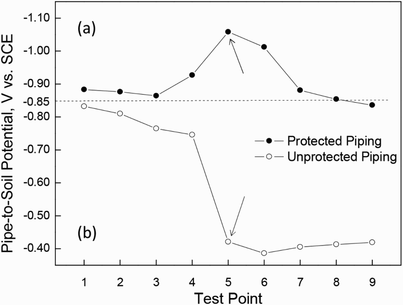
a protected by an external interference, measured using IOP method; distance between points, 100 m; arrow indicates crossing point of pickup; b unprotected by external interference, measured using the IOP method; distance between points, 100 m; arrow indicates crossing point of dischargePipe to soil potential versus reference points along pipeline
As an example, Fig. 10 shows the potential profile versus distance along the pipeline after eliminating the interference using a direct low resistance connection, which means that the E corr of the protected pipeline affected by the interference is now showing more reliable potential readings. A test station is usually installed to verify the electrical continuity and to measure the current flowing across the bond.
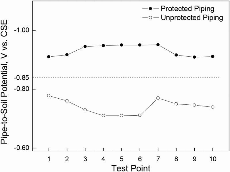
Pipe to soil potential versus reference points along protected and unprotected pipeline, measured using IOP method. Distance between points, 100 m
In some cases, the installation of an anode bed attached to the foreign pipeline may be used as another method to eliminate the interference. Even so, it is common for the interference to be not completely solved and a low resistance bond may still be needed. The anode bed has to be calculated to provide enough current to balance the interference current.
Buried pipes with little or no CP applied
Close interval survey studies are also used to look for sharp changes in the voltage gradient on pipes that have little or no CP applied.
Two types of surface potential gradient surveys are used to identify possible anodic areas on a pipeline: (i) surveys measuring gradients along the pipeline (hot spot survey) and (ii) surveys measuring gradients perpendicular to the pipeline (side drain survey). Both techniques can be performed as a stand alone survey or can be combined with CIS. Hot spot surveys are useful to determine anodic zones on pipelines without electrical continuity or uncoated or poorly coated areas.8,16 Figure 11 shows the arrangement of a cell to cell potential gradient study of CP (a hot spot survey) involving the placement of two reference electrodes.
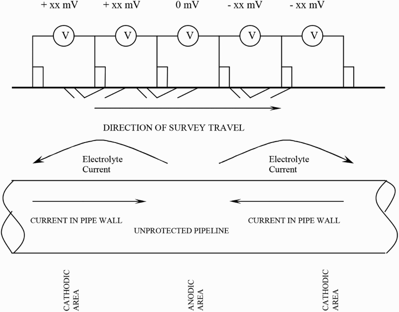
Layout of pipe surface study using hot spot survey method
If the pipeline is cathodically protected, hot spot and side drain surveys can be performed with the CP system applied, so as to evaluate its effectiveness, or be carried out with the CP de-energised and allowing enough time for the pipeline to depolarise to its native conditions, in order to evaluate corrosion behaviour before the installation of the CP system or during the intermittent application of the CP system.
If an inversion of polarity is detected, an anodic condition may be suspected and a decrease in the interval between readings provides a better and more precise location of anodic areas, see Fig. 11. The severity and extent of an anodic condition may be further determined by measuring the side drain potentials.
Conclusions
The performance of CISs incorporating the IOP method is a good approach to determine the integrity of a buried pipeline or underground metallic structure. Alternating current voltage gradient or direct current voltage gradient surveys can be simultaneously performed for a more in depth assessment.
Hot spot and side drain surveys can be carried out to study the effectiveness of both energised and de-energised CP systems, allowing enough time for the pipeline to depolarise to its native conditions. Additional measurements such as soil resistivity and pH conditions are useful to evaluate the corrosiveness of the surrounding soil and the pipeline maintenance.
Footnotes
Acknowledgements
The authors express their gratitude to Eng. C. K. Meier from Corrosion Control Inc., Rutledge, GA, USA, for the many discussions, and to CICYT, Spain (project no. DPI2011-26480) for financial support.