
Abstract
Excursion from safe cathodic protection (CP) potentials occurs on buried steel pipelines due to various forms of electrical interferences such as stray currents. Variations in pH can also occur over some pipeline sections such as seashore and river crossing pipes. Currently, the exact effects of potential excursion and the pH on CP efficiency have not been sufficiently quantified preliminary due to difficulties in measuring these effects. In this work, these effects have been investigated using electrochemical cells designed to mimic the high resistivity and pH conditions observable over underground steel pipes, including a new electrochemical cell that has been designed to facilitate the effective simulation and control of pH, potential excursion and other CP testing parameters. The pH has been shown to be a key factor affecting the patterns of corrosion and CP efficiency. Localised corrosion has been found to be the dominating form of corrosion under potential excursions conditions.
Keywords
Introduction
Cathodic protection (CP) is widely applied in conjunction with protective coatings as a principal means of protecting buried steel pipeline from soil corrosion. In order to ensure the effectiveness of CP, various industry standards and criteria have been developed over the past decades for selecting appropriate CP design parameters. In these industry standards, CP potential is typically considered to be the most important parameter; for instance, the Australian Standard AS 2832.1-1985 (Ref. 1) and the National Association of Corrosion Engineers (NACE) CP criteria 2 require the CP instant-off potential of a buried steel pipeline be set at − 850 mV[copper/copper sulphate reference electrode (CSE)]. Under this standard ‘safe’ CP potential level, a steel pipeline buried in pH neutral soil is considered to be fully protected although some doubts about the applicability of this standard CP potential to more complex environmental conditions still exist.3–7
Unfortunately in reality, the potential of a buried steel pipeline could be diverted from the designed safe CP level due to various reasons such as cathodic shielding of steel surface under disbonded coating8,9 and CP potential excursion due to electrical interferences. 10 These electrical interference signals may be direct current (dc), alternating current (ac) or ac superimposed on dc in nature, and are believed to be stochastic (i.e. the magnitude, duration and transient time are all random).10–16 The most common form of electrical interference is stray current that can be sourced, for example, from ac or dc powered tram or train railway systems. In some cases, stray currents could cause significant excursions from the standard CP potential of − 850mV(CSE)15–17 and can result in significant stray current corrosion damages to pipes buried near railway systems.18,19 A less known form of electrical interference on CP is telluric current, a natural electric current moving underground or through the sea. The telluric current transients can last from several seconds to several hours and have also been reported to cause damage to pipeline systems. 15
Although CP excursions are widely believed to be a major factor contributing to CP failure and pipeline corrosion, currently there is no unified consensus on how ‘big’ such CP excursion (either in magnitude or length or frequency) needs to be in order to cause major corrosion problems. Over the past decades, attempts have been made in order to achieve an unambiguous understanding of the effects of electrical interference signals on the corrosion of cathodically protected buried steel pipelines; however, most of the results and findings remain empirical. For instance, Peabody 20 described an empirical ‘rule’ that a dc excursion of 1 h duration would lead to 27% increases in buried pipeline corrosion risk, while a dc excursion of 1 day duration would increase the chance of corrosion by 50%. On the other hand, Wakelin et al. 12 described another ‘rule’ that no corrosion would occur if ac excursion current density is < 20 A m− 2; corrosion probably could occur when ac excursion current density is between 20 and 100 A m− 2, and corrosion is expected to occur when it is over 100 A m− 2. It should be noted that these empirical relationships are mostly developed from field observations and experiences of inspecting pipelines, and therefore, they could be distorted by many complex interrelated factors such as variable and dynamically changing soil environments. Indeed, prior work in this area has been predominantly based on empirical findings that are insufficient for achieving fundamental understanding of the phenomenon. This has left major uncertainties and difficulties in selecting suitable parameters in existing CP industry standards.
Technological difficulties in measuring and monitoring buried steel corrosion are believed to be the prime reason responsible for the lack of conclusive experimental data and evidences that could be used to effectively quantify the effects of CP excursions on buried steel corrosion. Currently, potential recording is the most commonly used method employed for monitoring stray current activities in the pipeline industry; however, potential recording does not provide sufficient information about CP efficiency, corrosion rates and patterns. Weight loss coupons and electrical resistance probes are used to measure corrosion rates of buried steel pipelines buried in soil; for instance, Barbalat et al. 21 used weight loss measurements to determine corrosion rates of steel coupons buried in sand under controlled conditions, and Birbilis et al. 22 used an electrical resistance probe array to measure corrosion on CP protected steel coupons buried in sand boxes under the effect of anodic transients. However, weight loss coupon tests only provide average corrosion rates over extended periods; such measurements are unable to provide in situ corrosion rate data required for quantifying the effects of relatively short term CP potential excursions on corrosion. The electrical resistance probe can collect useful corrosion data that are relevant to the corrosivity of sand; it usually cannot measure localised attack because localised corrosion may not lead to much resistivity changes of the probing element.
Electrochemical methods are widely used for corrosion measurement; however, in practice, electrochemical corrosion testing in highly resistive and inhomogeneous media can be very challenging due to several critical issues. The first issue is the practical problems associated with the installation, observation and maintenance of conventional two or three electrode cells for electrochemical testing in sand or soil. In highly resistive and inhomogeneous sand or soil, significant IR potential drops and non-uniform polarisation current distribution problems can cause difficulties in repeating experiments and significant uncertainties in data and its analysis. The second issue is the theoretical limitations associated with conventional electrochemical methods in measuring localised corrosion. In highly resistive and inhomogeneous sand, localised corrosion is often the key process triggering corrosion failure; conventional electrochemical methods have common limitations in measuring localised electrochemical thermodynamic and kinetic parameters because they are developed based on a uniform corrosion mechanism. 23 The third major issue is that CP introduces a significant complication to traditional electrochemical techniques since conventional electrochemical polarisation methods are designed for determining corrosion kinetics around the open circuit corrosion potential. The fundamental electrochemical equations are often not applicable at an externally applied CP potential that is often far away from the open circuit corrosion potential.23–25 Although Barbalat et al. 21 made an effort to determine corrosion rates of steel coupons buried in sand based on analysis of polarisation curves, corrosion measurement of buried steel pipeline under CP remains challenging when complex mechanisms and environmental conditions are taken into consideration.
A major effort in experimental determination of buried steel corrosion under CP excursions was made by Birbilis et al. 26 who used a sand box based electrochemical corrosion cell where a mild steel bar, a Ti mesh counter electrode and an Ag/AgCl reference electrode were buried in sand with selected resistivity (see Fig. 1a). The mild steel bar was subjected to the effects of CP excursions with different ratios of anodic and cathodic periods under potentiostatic or galvanostatic control. The currents applied to the steel bars were recorded and analysed based on Faraday's law, while the tested coupons were analysed by mass loss in order to obtain kinetic information regarding stray current corrosion in sands. Unavoidably, some difficulties were experienced in tests using this sand electrochemical cell due to the fact that sand is a highly inhomogeneous medium and the control of the humidity, resistivity and pH and their distribution in sand could be difficult. For instance, with the extension of testing, the sand resistivity can vary significantly with the depth of the sand in the cell. These practical issues make reproducibility of the measurement difficult to accomplish. For these reasons, technological difficulties in measuring and monitoring buried steel corrosion under CP have remained the prime reason responsible for the lack of understanding of the exact effects of CP excursions on CP efficiency and buried steel corrosion.
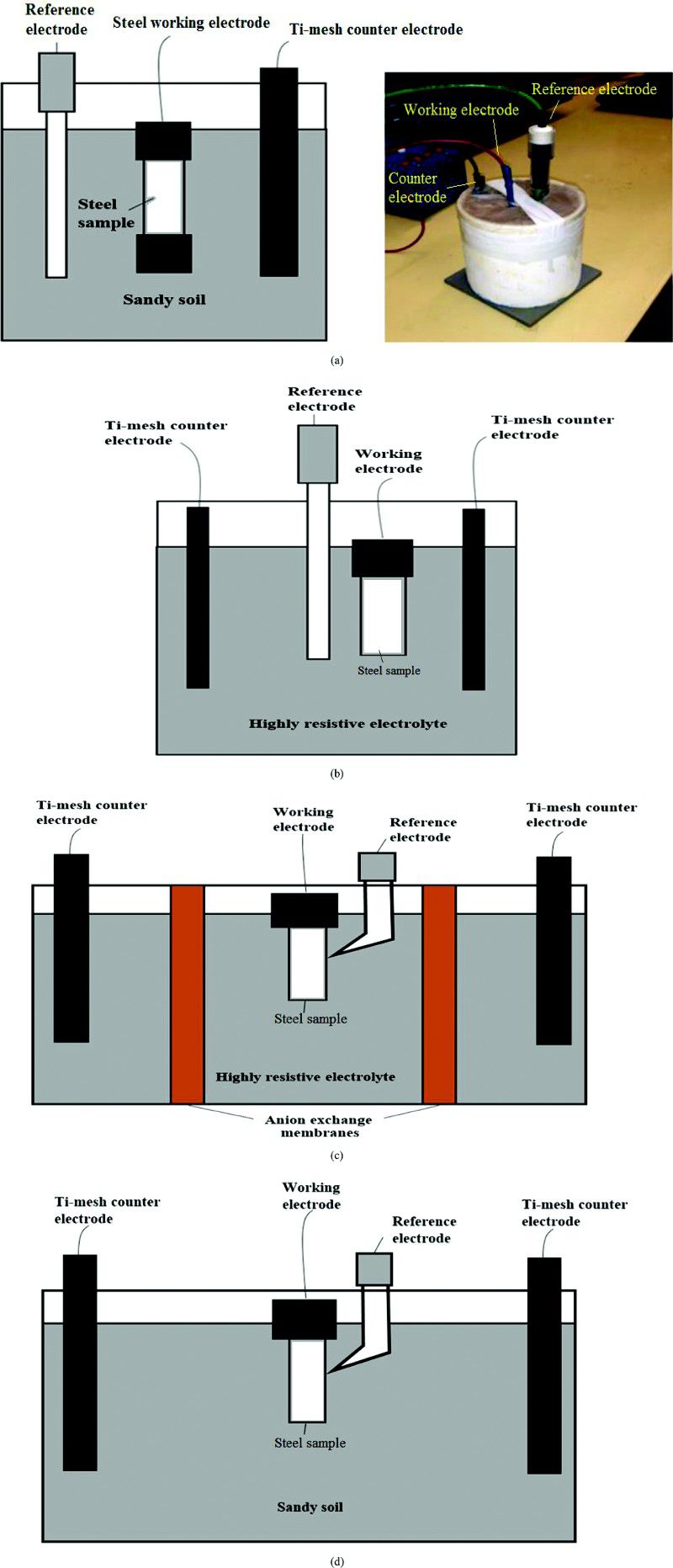
a sand box corrosion cell used previously in Ref. 26; b aqueous electrochemical cell; c new aqueous electrochemical cell design; d improved sand box electrochemical cell designElectrochemical cells designed for simulating sand corrosion and CP potential excursion conditions
This paper describes a new approach to addressing these technological difficulties by employing new electrochemical testing cells that are designed to mimic the high resistivity and pH conditions observable over underground steel pipelines, in order to facilitate effective control of potential excursions and the in situ monitoring, observation and understanding of corrosion processes. These new electrochemical cells have been applied in preliminary experiments for evaluating and quantifying corrosion in highly resistive media under the effects of potential excursion and pH conditions.
Experimental
The highly complex nature of sand and soil environments is a major obstacle for effective control of experimental variables that are essential for obtaining unambiguous data in sand or soil corrosion experiments; therefore, it is desirable to simplify the corrosion testing cell while still maintaining the expected chemical conditions at the electrode surface.
Design of new electrochemical testing cells
The first attempt of simplifying the control of experimental variables in the sand corrosion testing is the design of an aqueous electrochemical cell that employs an electrolyte to mimic the high resistivity and chemical environment in a sand box. In this design, as shown in Fig. 1b, a solution of typically 1000 Ω cm resistivity was used to achieve the same resistivity as sand in the equivalent sand cell shown in Fig. 1a. It is know that the most important sand property that significantly affects buried pipeline corrosion rate is sand resistivity, 27 and therefore, this aqueous cell is anticipated to simulate sand corrosion in a sand cell. A 5 × 5 cm square mild steel coupon of 0.3 cm thickness was used as the working electrode with both sides of the coupon exposed to the corrosive salt solution. Two Ti mesh electrodes were used as counter electrodes and were located on either side of the mild steel coupon. All other parameters were the same as those applied in the sand test cell. Possible advantages of this aqueous cell include easier control of testing conditions, in particular environmental uniformity, and avoiding practical difficulties associated with the installation, observation and maintenance of conventional two or three electrode sand or sand cells. This type of aqueous cells has been used in the past to investigate corrosion under various environmental and CP conditions; for instance, it has been used to mimic corrosion in sea water under the effects of stray currents, 28 for studying the influence of alternating voltages on passivation and corrosion properties of X80 pipeline steel in high pH solutions 29 and for investigating the effects of alternating current interference on coating disbondment on X65 pipeline steel. 30
Simulating buried steel corrosion conditions in aqueous media is a new endeavour. Although the electrochemical cell in Fig. 1b could effectively simulate the conductivity of the sand and the CP excursion condition applied on the steel surface, it became evident that the steel coupon surface in the cell could not establish the surface pH conditions of buried steel under CP. It is well known that the primary CP cathodic reaction, O2+2H2O+4e– → 4OH–, can lead to a high pH environment at the steel surface and induce passivation on buried steel surfaces. The simulation of this pH condition over steel surface is likely to be critical, and thus, modification of the cell design is needed to address this issue. Figure 1c is a new aqueous electrochemical cell design of an ion selective and conducting membrane that separates the electrolytes in the anodic and cathodic zones. The membrane is used to avoid the mixing of solutions from the anodic and cathodic zones, enabling the simulation of the steel surface pH conditions under CP. An anion exchange membrane, the AM(H)-PP membrane (a reinforcement fabric based on polyethylene and polypropylene, MEGA a.s. company, Czech Republic), was selected and employed as the separation wall between the working electrode and counter electrode because of its high ion selectivity and conductivity. 31 A Luggin probe was used to minimise IR drop.
A new sand box electrochemical cell, as shown in Fig. 1d, has also been designed and employed in parallel tests with the new aqueous cell. The sand box cell has exactly the same design as the aqueous cell, except that no membrane was used in the sand box cell. Sand is a highly resistive and inhomogeneous medium. Although many sand properties could affect buried steel's corrosion rates and CP efficiency, the most important sand property that has been identified to significantly affect bare pipe corrosion rate is sand resistivity. Corrosion in 1000 Ω cm sand resistivity is moderate, which has been appropriate for completing corrosion tests in a relatively short period of time. Therefore, 1000 Ω cm resistivity was used as a ‘base line’ solution resistivity condition in testing cells. Washed fine sand with typical resistivity of 1000 Ω cm was used in the sand box cell, and the resistivity was adjusted using an NaCl solution. The sand box cell was sealed to prevent evaporation. The resistivity of the sand in the cell was monitored, and only 50 Ω cm increase in resistivity was noted after 15 days of test.
Simulation of CP potential excursion conditions
As shown in Fig. 2, a potentiostate (Bio-Logic Science Instrument) was used to apply regular CP and also to apply the electrical interference signals under potentiostatic control. The experiments began by applying a standard CP potential of − 850 mV(CSE) on the steel coupon for the first 24 h in order to establish a stable baseline CP condition. An electrical interference signal was then superimposed on the CP potential in order to study the effects of CP excursions on steel corrosion behaviour. The ‘baseline’ interference signal was a sine wave of 1 cycle/min with 250 mV amplitude (see Fig. 2). That is, a ± 250 mV excursion from the standard CP potential, − 850 mV(CSE), was applied to the steel specimen as the ‘baseline’ interference signal. Currents applied to the electrochemical cells were monitored and recorded. Corrosion on corroded coupons were measured or recorded by visual observation, photographs, microscopic observation and profilometry measurement. Before microscopic observations, coupon surfaces were cleaned with the Clark solution. 32
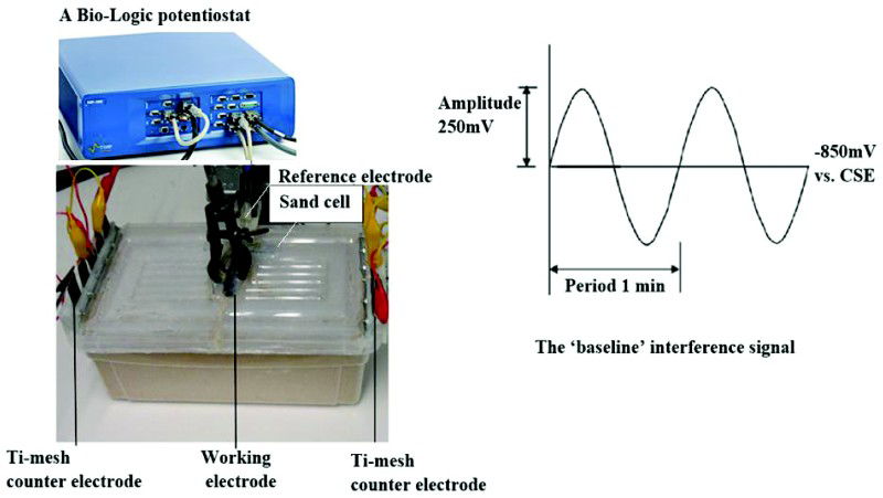
Schematic diagram illustrating test in improved sand box electrochemical cell where ‘baseline’ interference signal (sine wave of 1 cycle/min with 250 mV amplitude) was superimposed on standard CP potential of − 850 mV(CSE)
Results and discussion
The electrochemical cell shown in Fig. 1b is characterised by the fact that the diffusion of ions in the aqueous CP cell is not controlled. Although CP was applied to the steel specimen surface in the cell, as shown in Fig. 3, significant general corrosion occurred on the steel coupon surface after only 5 days of testing (under a standard CP potential for the first 24 h and a ‘baseline’ ± 250 mV interference signal for the next 4 days). A high general corrosion rate of ∼1 mm/year was recorded from the coupon surface. The corrosion behaviour and pattern shown in Fig. 3 is very different from buried steel corrosion typically expected under CP in a sand or soil environment. It is apparent that this aqueous corrosion cell was unable to simulate the corrosion condition of a buried steel structure such as a pipeline. This is believed to be primarily due to the fact that the pH of the CP cell is not controlled, and therefore, the aqueous cell failed to simulate a high pH condition commonly developed over a buried steel pipeline surface. Indeed, pH measurements indicated that the solution in the aqueous cell remained near neutral (pH fluctuated between 5.9 and 7.2 over the first 4 days of test), while the pH of a CP protected steel pipeline should normally be retained at a value of between 10 and 14. This near neutral pH is insufficient for steel to achieve passivity even under the applied CP let alone when a perturbation is superimposed.
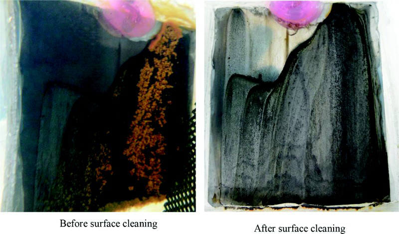
Photo of steel coupon surface after 5 days of test in an aqueous electrochemical cell shown in Fig. 1b: standard CP potential − 850 mV(CSE) was applied for first 24 h and ‘baseline’ sine wave of 1 cycle/min with 250 mV amplitude was superimposed on CP potential for next 4 days
This experiment suggests that the effectiveness of CP could only be achieved if the pH at the steel surface increases to achieve passivity. Indeed, this testing cell may simulate relatively uncommon and probably ‘the worst case’ conditions that do not allow pH increase, for instance, if coating defects are immersed in running soft water along the pipeline trench. These results are in agreement with the analysis on the ‘true nature’ of CP pointed out by Buchler: 33 the actual protection mechanism appears to involve shifting the metal surface into the passive or immune zone of the Pourbax diagram. 34 This results clearly suggest the significance of pH induced steel surface passivity in CP mechanism and efficiency.
The significance of pH in CP efficiency and corrosion behaviour has been confirmed in another experiment carried out using the new electrochemical corrosion cell, as shown in Fig. 1c, that the pH of the CP cell was controlled by separating anodic and cathodic zones of the aqueous cell. In this aqueous electrochemical cell, pH of the cathodic zones maintained values between 9 and 10, suggesting passivity of the steel coupon (note: the anodic zones had pH values ∼3). Completely different corrosion pattern, as shown in Fig. 4, was observed on the steel coupon surface after 15 days of test in the electrochemical cell (under standard CP potential for the first 24 h and a ‘baseline’ interference signal for the next 14 days). Corrosion in the cell was predominantly localised with the corrosion rate recorded from pitting reached 0.8 mm/year, while the corrosion rate of the overall surface was only 0.07 mm/year. These results are in agreement with the potential–pH diagram of iron that shows that the passivation for iron requires a pH around 9-12 (an example is shown in Fig. 7). 34 This behaviour is similar to that observed on practical CP protected buried steel pipeline surfaces where pits are the most common form of corrosion. This result is also in agreement with field observations that high pH developed by the cathodic reactions at the exposed metal on a buried pipeline is necessary for buried steel pipelines to form a protective passive film on the exposed steel pipe surface.
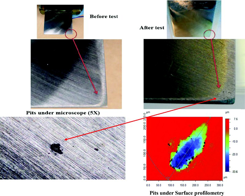
Photos and a profilometry image of steel coupon surface before and after being exposed to sand electrochemical cell shown in Fig. 1c, and being tested under standard CP potential for the first 24 h and ‘baseline’ interference signal for next 14 days
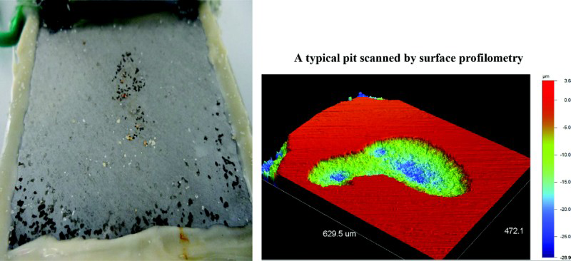
Photo and profilometry image of steel coupon surface after being exposed to sand box electrochemical corrosion cell shown in Fig. 1d and being tested under standard CP potential for first 24 h and ‘baseline’ interference signal for next 14 days
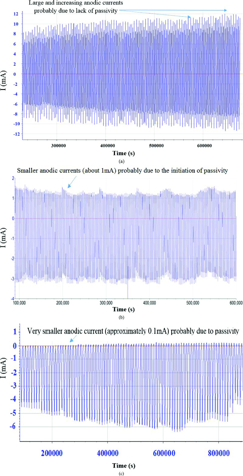
Current recordings logged from cells shown in Fig. 1b–d respectively
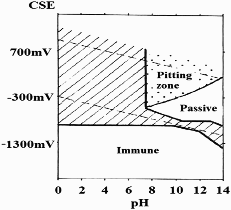
Pourbaix diagram of pitting and protection of iron in chloride containing media ([Cl− = 10− 1M) 34
The corrosion behaviour observed in the new electrochemical corrosion cell is also similar to that observed from a sand electrochemical cell shown in Fig. 1d, as shown in Fig. 5, after 15 days of test (under standard CP potential for the first 24 h and a ‘baseline’ interference signal for the next 14 days). Corrosion is highly localised with pits observable over the coupon surface. Typical pitting corrosion rate of ∼0.74 mm/year was recorded.
Figure 6 shows electrical currents applied to the electrochemical cells that were monitored and recorded by the potentiostat. It can be seen that large anodic currents with values of ∼10 mA (see Fig. 6a) were recorded from the cell shown in Fig. 1b. This is in agreement with high corrosion rate (∼1 mm/year) observed in the cell that had a near neutral pH value. Significantly lower anodic currents with peak value of ∼1 mA (see Fig. 6b) were recorded from the cell shown in Fig. 1c. This is in agreement with the fact that much lower general corrosion occurred in the corrosion cell (∼0.07 mm/year) shown in Fig. 1c. This experiment suggests that the effectiveness of CP can only be achieved if the pH at the steel surface increases to achieved passivity. However, it should be noted that passivity was not stable in this cell because significant localised pitting occurred in the cell (up to 0.8 mm/year). Very low anodic currents with a peak value of 0.1 mA (see Fig. 6c) were recorded from the cell shown in Fig. 1d. This very low anodic current suggests a passive steel surface that allowed low anodic dissolution reactions and low general corrosion. However, localised pitting still occurred on the steel surface under the effects of simulated interference signal.
The corrosion behaviours and patterns observed in both aqueous and sand box cells described above are in agreement with field observation of CP protected buried steel pipeline surfaces where pits are the most common form of corrosion. A high pH is also observed at the exposed metal area (at coating defects) that is necessary for effective CP. It should be noted, however, that the cell shown in Fig. 1c still not fully simulates the pH and oxygen transportation conditions of buried steel pipeline CP systems, although it does produce a passive condition, and thus, corrosion behaviour in the cell is similar to that observable on buried pipeline surface. This testing cell may best simulate the ‘worst case’ conditions that could experience in practical pipeline systems, for instance, seashore and river crossing pipes as well as flooded pipeline sections. Advantages of this electrochemical cell include easy control of conditions and parameters that are essential for achieving better test reproducibility. Furthermore, the surface of the steel coupon is visible in the transparent electrolyte solution; therefore, it enables in situ observation of corrosion processes and patterns. It has been employed in our current research in order to achieve a comprehensive and unambiguous understanding of the effects of various forms of electrical interference signals of various magnitude, transient time and frequency on the corrosion rates and patterns of cathodically protected underground steel pipelines.
In order to better simulate and investigate more complex factors and environmental conditions affecting CP and corrosion, electrochemical cells described in this paper can be modified by changing the electrolyte type, composition, shape and dimensions. For instance the media in the cells can be made to simulate beach soil environment with different degrees of soil aeration and microbial activity for research on corrosion behaviour of oil exploitation steel structures. 35 In order to better simulate different water environments, additional sulphate, carbonate, bicarbonate as well as divalent cations such as calcium can be added to the electrolyte. It is known that a passive film or a calcareous film might be formed in such electrolyte. Furthermore, a gel electrolyte could be used to simulate different ion diffusion behaviours and its effect on the passivity of steel. The dimension and shape of the cell can also be changed to simulate more complex underground environment where high resistivity stratum, such as rock, may exist and affects the diffusion and pH conditions in the cell.
Conclusions
New electrochemical cells have been designed to simulate and investigate corrosion and CP of buried steel under the effects of CP excursions and pH variations. A new aqueous cell was designed to mimic the corrosion behaviour of buried steel under the ‘worst case scenario’ CP conditions, enabling better control of testing parameters and in situ observation of corrosion processes and patterns. Localised corrosion has been found to be the dominating form of corrosion under simulated pipeline pH conditions, while pH has been shown to be a key factor affecting the pattern of corrosion. The effects of potential excursions and pH variations have been explained by changes in passivity of steel.
Footnotes
Acknowledgements
This work was funded by the Energy Pipelines Cooperative Research Centres (EPCRC), supported through the Australian Government's Cooperative Research Centres Program. The funding and in-kind support from the APIA RSC is gratefully acknowledged. We also acknowledge EPCRC industry advisers, A. Bryson, B. Ackland, B. Martin, G. Cope and C. Bonar, for their comments on our research.