
Abstract
In this paper, the deposition of Ni–Al–N coatings on Nimonic 75 substrates using a 4 kJ plasma focus device for 30 shots is investigated. The results obtained by field emission scanning electron microscopy and X-ray diffraction (XRD) tests confirm the formation of Ni–Al–N nanoparticles on the surface of the samples with an average crystalline size of ∼20-50 nm. The hot corrosion rate was determined by measuring the weight gain of the samples at 800°C. Improvement of charge transfer resistance by electrochemical impedance spectroscopy reveals that the coated layer can significantly increase resistance to corrosion.
Introduction
Ni–Al–N coatings are extensively used for industrial applications such as glass moulding dies and forming tools 1 and tribological and thermal barrier systems 2 due to their excellent wear and oxidation resistance,1,3,4 higher hardness and corrosion resistance. 4 Various techniques such as radio frequency magnetron sputtering in different argon–nitrogen atmospheres, 1 pulse electrodeposition 4 and closed field unbalanced magnetron sputter ion platting 2 are employed to deposit Ni–Al–N thin films.
The dense plasma focus (DPF) device is a pulse discharge device that is composed of two co-axial electrodes, a capacitor bank, a fast spark gap switch and a vacuum chamber. These devices can generate high density (∼1025–1026 m− 3), high temperature (1-2 keV) and short lived plasmas (100 ns) by utilising the self- generated magnetic field.5,6 The DPF is source of fusion neutrons, X-rays, relativistic electrons and energetic ion beams. 7 The ion beam energy of a DPF is dumped onto a near surface layer of the material for the duration of a few tens of nanosecond. Consequently, the surface is heated up to several thousand degrees centigrade in a short time, and it is immediately followed by fast melting and resolidification. The high cooling rates can result in the production of new phases in the near surface layer. Therefore, ion beams of DPF device have drawn considerable attention in surface modification in recent years.7–10 Al-Hawat et al. 10 used a 2.8 kJ DPF to surface modification of AISI304 steel. They reported that the surface hardness of AISI304 steel was increased by ∼175% after plasma treatment and the thickness of the treated layers was ∼1-2 μm. Hassan et al. 7 deposited TiN thin films on titanium samples by utilising energetic nitrogen ions emitted from a 2.3 kJ DPF. Sidhu et al. deposited NiCrBSi coatings on Ni and Fe based superalloys by high velocity oxyfuel process. 11 Kamal et al. deposited Cr3C2–NiCr coatings on Ni and Fe based superalloys by detonation gun thermal spray process. 12 Wang et al. 13 evaluated oxidation behaviour of NiCrAlY coatings on IN100 superalloy. These studies illustrated that the hot corrosion resistance and microhardness of the coated samples were improved as compared with the uncoated specimens. Vyas and Choy deposited (8 wt-% YSZ) on the Nimonic 75 by the electrostatic spray assisted vapour deposition technique with the crystallite size of ∼4 nm. 14 Xu et al. studied the thermal barrier coatings for the gas turbine blades by the electron beam physical vapour deposition method. 15 Kameda et al. evaluated mechanical properties of aluminised CoCrAlY coatings of advanced gas turbine blades. 16 Mobarra et al. investigated the hot corrosion of CoNiCrAlY coatings deposited on the IN738LC superalloy by the low pressure plasma spray technique using samples immersed in a solution of Na2SO4–10 wt-% NaCl. 17 Gurrapp studied the hot corrosion resistant MCrAlY based bond coatings for gas engine applications. 18 He showed that the electrochemical techniques are quite useful in evaluating coatings for hot corrosion resistance.
In this work, we presented the result of Ni–Al–N coating on the surface of Nimonic samples. The idea here is to use nickel and aluminium fitted anode tips of a 4 kJ plasma focus device operating with nitrogen gas and to study the effect of ion beam irradiation on the samples for 30 plasma focus shots. Characterisation of Ni–Al–N coatings using field emission scanning electron microscopy (FESEM) and X-ray diffraction (XRD) has been studied. The hot corrosion rate was determined by measuring the weight gain of the samples at 800°C.
Experimental
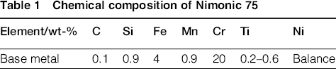
Figure 1 shows a picture of the APF device and the electrode assembly. 19 The experiments were performed by the APF device (15 kV, 40 μF, 115 nH) with a maximum storage energy of 4 kJ. 20 Two-layer coating of Al–N and Ni–N was deposited onto the Nimonic 75 substrate. The chemical composition of the Nimonic 75 is given in Table 1.
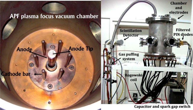
Right: picture of APF device; left: vacuum chamber of device
Chemical composition of Nimonic 75
For the first deposition process, the anode target material was Al anode tip, and for the second deposition process, the anode tip material was Ni and working gas for both deposition processes was N. At a voltage of 12 kV, the optimum pressure of nitrogen gas (N) is found to be 2 Torr and 15 focus shots were applied for every deposition process. 21
Five Nimonic 75 samples were used to treat with different plasma shots. By analysing the treated surfaces, 30 plasma shots were selected. The samples of 20 × 20 × 1 mm3 dimensions are placed above the anode tip at 5 cm axial position and are irradiated for 30 focus shots.
22
The energetic nitrogen ions reach the substrate and implanted on samples, sputtered Ni and Al ions from the insert material combined with the background nitrogen ions, and reaction of ablated Ni and Al with Nimonic samples.
6
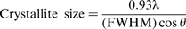
Structural properties of Ni–Al–N coating were then analysed using SEM, XRD, electrochemical impedance spectroscopy (EIS) and hot corrosion techniques. The average crystallite size is calculated using Scherrers formula
22
:
EIS tests were performed at the open circuit potential with an applied AC perturbation of 10 mV over the frequency range from 10 mHz to 100 kHz. The EIS tests were conducted with PGSTAT 302N of Metrohm Autolab using NOVA V1.9.17 software. The ZSimpWin V3.21 impedance analysis software was used to fit the achieved data. Electrochemical measurements were conducted using a conventional three-electrode electrochemical cell with the samples as the working electrodes, a platinum plate as the auxiliary electrode and a saturated calomel electrode. As shown in Fig. 2, the samples were drilled from the corner, and after connecting the copper wire and soldering, junctions and uncoated area were covered with epoxy insulator to prevent the galvanic effect. Afterwards, the samples were placed in an oven for 12 h. The area of the sample exposed to the EIS measurement was 1 cm2.
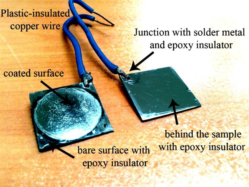
Preparation of samples for EIS measurements
All experiments were carried out at room temperature. The corrosive electrolyte employed was naturally aerated 7 wt-% sodium chloride (NaCl) and 21 wt-% sodium sulphate (Na2SO4) solution. The parts of the samples that are not coated to prevent the galvanic effect of the base metal and coating were isolated. Afterwards, the samples were placed in an oven for drying for 12 h.
Hot corrosion behaviour of the coating specimens was performed in a tube furnace. After washing with acetone, specimens were primarily preheated to 200°C and subsequently sprayed with a 90 wt-% Na2SO4 + NaCl solution with ∼5 mg cm− 2 of corrosive mixture at a distance of 50 cm. The volume used to dissolve the mixture was 1000 cm3 (1 L) H2O. The heating of the specimens was found necessary for proper adhesion of the salt layer. At the end of each cycle, the weight of specimens was measured with a sensitivity of 10− 5 g. High temperature hot corrosion resistance of samples was started by inserting the samples into a furnace at 800°C for 140 h.
Results and discussion
The XRD pattern of the treated sample is shown in Fig. 3. The X-ray diffraction pattern of virgin material shows peaks at 44.06°, 51.28° and 75.56°. This is due to Ni. 10 Diffraction pattern shows the presence of peaks at 2θ = 44.48° and 2θ = 91.43°, which corresponds to phases Ni3N(111) 23 and Ni3N(004) 22 respectively. The diffraction peak of the 30 focus shots shows the presence of AlNi3 (220) at 2θ = 75.29° (refer to JCPDS card no.00-050-1265).
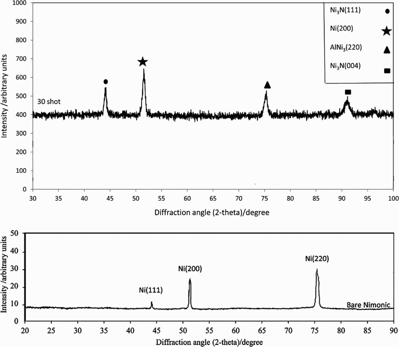
XRD patterns of bare and treated Nimonic samples
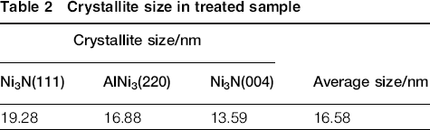
Table 2 shows the crystallite size in the treated sample after 30 shots.
Crystallite size in treated sample
Surface morphology of the grains is shown in Fig. 4b with a radius average of ∼20-50 nm.
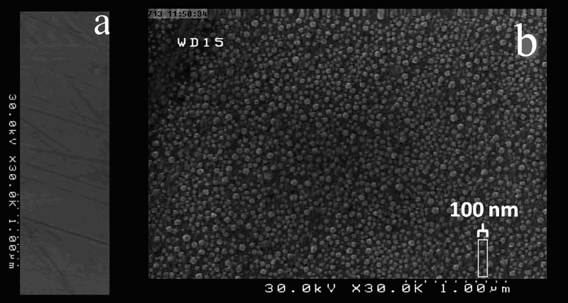
FESEM of bare and coated sample showing formation of Ni–Al–N nanocrystals: a bare Nimonic 75; b coated Nimonic 75
Figure 5 shows the Nyquist plots of the uncoated and coated specimen as a result of EIS tests. As it is seen, both diagrams over the entire frequency range have maintained their semicircular form. An equivalent circuit analysis was conducted using the Zsimp software. The equivalent circuit proposed to analyse the EIS spectra is shown in Fig. 6. In these circuits, R 1 corresponds to the solution resistance, R 2 to the film resistance due to the formation of the oxide layer, R 3 to the charge transfer resistance, and C to the electrical capacity of the oxide layer. Q 1 is a constant phase element (CPE) of the coated layer, and Q 2 is the CPE at the double layer.
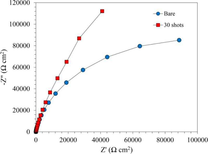
Nyquist diagrams of both bare and coated specimens in mixture of 7 wt-% NaCl and 21 wt-% Na2SO4 solution
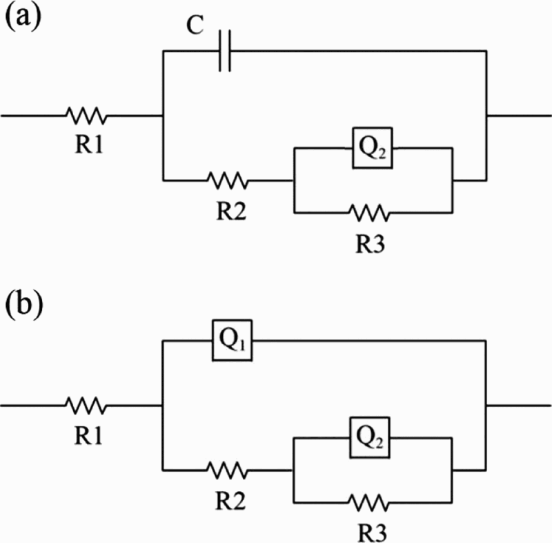
Equivalent circuit proposed for electrochemical impedance response for both bare and coated specimens in mixture of 7 wt-% NaCl and 21 wt-% Na2SO4 solution
The impedance of a CPE is defined by the empirical expression
24
:

Values of electrochemical equivalent circuit elements as results of EIS tests for both bare and coated specimens in mixture of 7 wt-% NaCl and 21 wt-% Na2SO4 solution
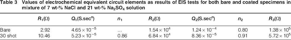
As it can be seen from Fig. 7 and Table 3, in the bare specimen, the terms of R 1 and R 2 are lower than the coated specimen and the terms of corrosion resistance (R ct) and film resistance (R f) are increased. In other words, the coated specimen exhibited much better corrosion resistance in the presence of sodium, chlorine and sulphur ions.
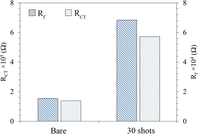
Comparison of corrosion resistance (R ct) and film resistance (R f) for both bare and coated samples
Figure 8 shows that the bare Nimonic 75 has higher weight gains compared with Nimonic 75 implanted with Ni–Al–N ions.
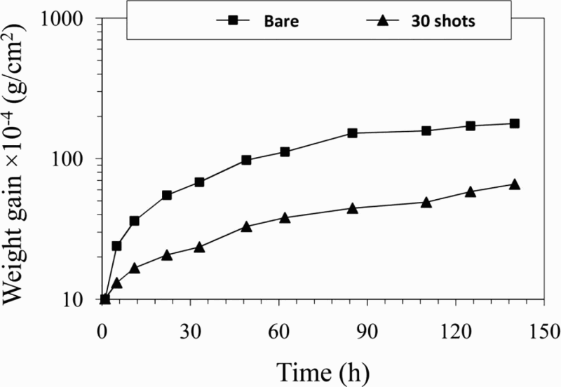
Weight gain for coated and uncoated Nimonic 75
Conclusions
Ni–Al–N thin films have been deposited into Nimonic 75 using a 4 kJ DPF device for 30 shots in order to improve the hot corrosion resistance of Nimonic. Hot corrosion, EIS and microstructure changes in Nimonic 75 with Ni–Al–N coatings were studied in this paper. The results obtained by FESEM and XRD tests confirm the formation of Ni–Al–N nanoparticles on the surface of sample with an average crystalline size of ∼20 nm. According to EIS results, improvement of charge transfer resistance from 1.38 × 10⁵ Ω for bare Nimonic to 5.72 × 10⁵ Ω for the 30 shots sample reveals that the coated layer can significantly increase resistance to corrosion. Therefore, we believe that plasma focus devices are useful devices for improvement of hot corrosion resistance on Nimonic 75 alloy and other applied materials.