
Abstract
The MAX phases are a group of layered ternary compounds with the general formula Mn+1AXn (M: early transition metal; A: group A element; X: C and/or N; n = 1–3), which combine some properties of metals, such as good electrical and thermal conductivity, machinability, low hardness, thermal shock resistance and damage tolerance, with those of ceramics, such as high elastic moduli, high temperature strength, and oxidation and corrosion resistance. The publication of papers on the MAX phases has shown an almost exponential increase in the past decade. The existence of further MAX phases has been reported or proposed. In addition to surveying this activity, the synthesis of MAX phases in the forms of bulk, films and powders is reviewed, together with their physical, mechanical and corrosion/oxidation properties. Recent research and development has revealed potential for the practical application of the MAX phases (particularly using the pressureless sintering and physical vapour deposition coating routes) as well as of MAX based composites. The challenges for the immediate future are to explore further and characterise the MAX phases reported to date and to make further progress in facilitating their industrial application.
Introduction
Metallic materials are typically characterised by being thermally and electrically conductive, plastically deformable at room temperature, readily machinable, thermal shock resistant, damage tolerant, relatively soft, etc. On the other hand, ceramics are generally characterised by high elastic moduli, good high temperature mechanical properties, good oxidation and corrosion resistance, etc. The relatively recent discovery of a family of new materials, namely the MAX phases1 (also termed in some publications ‘metallic ceramics’2) has provided materials that possess a useful combination of both metallic and ceramic characteristics.
The term ‘Mn+1AXn phase’ was used for the first time by Barsoum in 2000.1 In the general formula Mn+1AXn, later abbreviated to MAX,3 M represented an early transition metal, A represented an A group element, X represented C and/or N, and n = 1–3. The labelling of A group elements in the periodic table came from the old CAS notation: today, the MAX phase A-group elements are drawn from columns 13–16 in the periodic table. The transition metal, M, elements that form MAX phases are: Sc, Ti, V, Cr, Zr, Nb, Mo, Hf and Ta; the A-group elements are Al, Si, P, S, Ga, Ge, As, In, Sn, Tl and Pb. In an isolated case, Cd was also reported to form MAX phase by taking the position of A. Depending on the value of n, the M2AX, M3AX2 and M4AX3 phases are usually referred to 211, 312 and 413 phases respectively. Experimental or calculated evidence has also been advanced for the existence of higher order MAX phases such as 514,4 615,5 and 716.6 Table 1 summarises basic data for the MAX phases that have been experimentally synthesised, alongside information on phases that have been proposed on the basis of structural observations at the unit cell level and/or theoretically predicted from calculations.
MAX phases reported in literature as having been experimentally synthesised, proposed and/or theoretically predicted, and some fundamental properties*: solid solutions, except those without end members reported, are not listed; polymorphs calculated as unstable are not listed
*ρ 0: resistivity at 300 K; α: temperature coefficient of resistivity; CTE: coefficient of linear thermal expansion; κ: thermal conductivity; C p: specific heat capacity at 300 K; E: Young’s modulus; B: bulk modulus; HV: Vickers hardness; σ c: compressive strength; σ f: flexural strength. Numerals in superscript denote references.
†Calculated value.
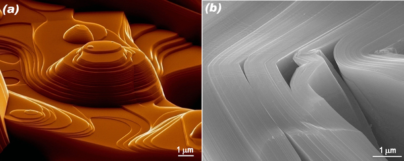
The MAX phases are all layered hexagonal structures with space group P63/mmc (no. 194). They consist of alternate near-close-packed layers of M6X octahedra interleafed with layers of pure A atoms. The M6X octahedra, similar to those forming in the respective MX binary carbides, are connected each other by shared edges. The main differences in the structures of the 211, 312 and 413 phases lie in the number of M layers in between every two A layers. As can be seen in Fig. 1, two, three and four M layers exist in between every two A layers in Ti2SC, Ti3SiC2 and Ta4AlC3 crystal structures respectively. Such atomic arrangements lead to the characteristic layered structures of the MAX phases. For instance, Fig. 2a shows an SEM micrograph of a surface feature of a Ti3SiC2 grain growing inside a pore, where the preferential growth of the basal planes is prominent. The layered nature of the MAX phases when deformed can be better appreciated from Fig. 2b , showing deformed nanolaminates.7,8
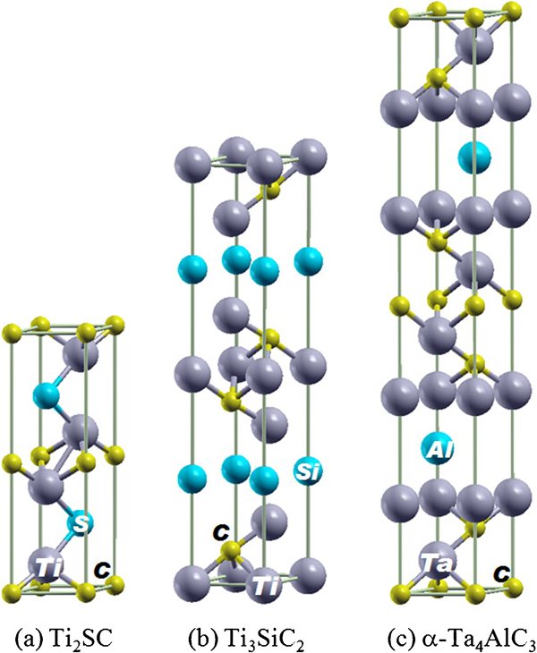
Unit cells of three representative MAX phases
Crystallographic features of Ti3SiC2
The study of the MAX phases dates back to the work published in the early 1960s by Nowotny and his group in Vienna, who sometimes labelled them the M2BC phases and sometimes the H-phases.9 Among the compounds reported are more than thirty 211 phases. In 2000, Barsoum listed forty-six 211 phases.1 If one ignores solid solutions, the length of this list has not changed since then, in terms of the occurrence of the 211 phases, though more have been theoretically predicted.10 – 14
Ti3SiC2, a 312 compound, is the most extensively studied MAX phase so far. In 1967, the Vienna group discovered both this compound15 and Ti3GeC2.16 The atypical nature of the MAX phases was first reported on by Nickl et al. in 1972,17 who found Ti3SiC2 to be anomalously soft for a transition metal carbide. Later, Goto and Hirai18 fabricated a 0·4 mm thick Ti3SiC2 polycrystalline ‘plate’ by chemical vapour deposition (CVD) and confirmed the earlier observation of Nickl et al. These early work apparently encouraged the development of bulk Ti3SiC2 and other MAX phases.
The number of 312 phases remained at two, until the early 1990s when Ti3AlC2 was discovered.19 Very recently, however, the 312 family doubled in size with the discovery of Ti3SnC2,20 – 22 Ta3AlC2,5,23 and (V0·5Cr0·5)3AlC2.24 The latter is quite intriguing; neither of the end members, V3AlC2 or Cr3AlC2, crystallises in the 312 configuration. Furthermore, V3SiC2 (Ref. 10) and Nb3SiC2 (Ref. 25) were predicted to be slightly metastable, by first-principles calculations. This opens the door for their possible synthesis by some non-equilibrium processes such as thin film technology.
The first 413 phase, Ti4AlN3, was discovered in 2000,26,27 nearly 40 years after the 211 phases, and for a while was believed to be the only one. Metastable Ti4SiC3 (Ref. 4 and 28–30) and Ti4GeC3 (Ref. 29 and 31) were found during epitaxial thin film synthesis. Bulk Ta4AlC3 has recently been synthesised and extensively studied.5,23,32 – 40 More recently, Nb4AlC3,40 – 43 V4AlC3,40,44,45 and Ti4GaC3,46 were discovered. The rapid expansion of the list of the MAX phases, particularly in the 413 phases, is encouraging and suggests that this is a fruitful line of research for the discovery of new MAX phases. It is important to note here that not all phases listed above have been fabricated in bulk, pure single-phase form.
Lin et al. 5 reported the existence of regions of Ta6AlC5 structure in direct atomic resolution observations of the layer stacking characteristics of TaCx slabs and Al atomic planes in the Ta–Al–C system. Similarly, regions appearing to possess a Ti7SnC6 structure were recently observed in hot pressed Ti–Sn–C samples.6 Although currently relating to structures on the scale of unit cells, these results indicate the possibility that higher order MAX phases may exist.
The early review of Barsoum in 2000,1 and his introductory article3 have substantially galvanised the research field, some of the fundamental knowledge of the MAX phases can be found therein. The current status in Ti3SiC2 (Ref. 47) and some ternary carbides48,49 can be found in some recent reviews, for example that by Barsoum.50
In the present review, emphasis will be placed on the progress made in recent years on the synthesis and characterisation of the MAX phases.
Synthesis
Synthesis of bulk MAX phases
Early synthesis of Ti3SiC2 involved either reaction of gaseous reactants at temperatures as high as 2273 K,15 or by CVD.17,18 These processes, however, are not practical methods for fabricating engineering materials in the bulk form. Lis and co-workers published a series of papers over nearly 10 years, on the synthesis of bulk Ti3SiC2.99 – 103 They used combustion synthesis, and later in combination with hot isostatic pressing (HIP). However, their attempts always resulted in samples containing ancillary unwanted phases, mostly, TiC. Their best samples contained about 80–90 vol.-%Ti3SiC2.
While combustion synthesis is merited by its rapid reactions, in as short as a few seconds, but with sacrificed product quality, Barsoum et al. 65,104,105 employed hot pressing (HP) or HIP for the synthesis of nearly single phase bulk Ti3SiC2 polycrystalline samples. Such processes were soon extended to the synthesis of many other MAX phases, such as Ti3GeC2, Ti2AlC, Ti2AlN, Ti2GeC, V2AlC, Ta2AlC and Nb2AlC.65 Later, this reactive HIP process was used to fabricate predominantly single phase samples of Ti3AlC2.91 Zhou et al. 106 used an in situ HP solid–liquid synthesis of dense Ti3SiC2, that resulted in ∼92 wt-%Ti3SiC2.
The issue of bulk MAX phase synthesis was also tackled using pulse discharge sintering (PDS), also known as spark plasma sintering. The PDS process employed for the synthesis of the MAX phases is similar to reactive HP, however, with some advantages over the latter. The PDS process was used to fabricate bulk Ti3SiC2, starting with various molar ratios of reactants, such as Ti/Si/C,107 – 110 Ti/SiC/C,107,111 Ti/Si/TiC,112 – 115 Ti/SiC/TiC,116 and Ti/TiSi2/TiC.117 In most cases, predominantly single phase, fully dense compounds were reactively sintered in as short as a few minutes. This method was also employed to synthesise Ti3AlC2,118 – 122 and Cr2AlC,75,123 among others.
However, the reactive sintering processes outlined above, such as HP, HIP or PDS, cannot easily be applied to the mass production of MAX phase parts. Pressureless sintering from powder green compact without mechanical pressure, i.e. pressureless sintering, is much more economical and scalable.
Early attempts of pressureless sintering were first made via mechanical alloying (MA) and sintering process, which all ended up with a high content of unwanted secondary phases.124,125 Sun et al. 126 reported on the successful synthesis of high phase purity and density Ti3SiC2, by reactive pressureless sintering (patented). The addition of small amounts of Al was found to improve the density of the compacts and to enhance the formation of the target phase, Ti3SiC2.127 Fabrication of Ti3SiC2 by tape casting and/or cold pressing, followed by pressureless sintering of the commercial Ti3SiC2 powders were also reported.128,129 Such pressureless sintering processes from the respective phase pure compound powders are a promising practice for application.
Synthesis of MAX phase films
The early CVD work on the deposition of Ti3SiC2 films resulted in single phase samples with anomalous properties.17,18 Intriguingly, later CVD work on Ti3SiC2 failed to produce single phase films.130 – 132 This problem was mitigated in a study of the deposition of (SiC/Ti3SiC2)n multilayered films.133 It follows that the use of CVD for the formation of the MAX phases has to date been limited, and only explored for Ti3SiC2. Problems with phase purity and process control are likely the causes for the limited interest in using CVD for MAX phases.
Much more rapid and fruitful results were obtained when the attention was turned from CVD to physical vapour deposition (PVD). Ti3SiC2 films were successfully synthesised by magnetron sputtering.4,28,134 – 136 Similar results were obtained in the Ti–Ge–C,31 Ti–Al–C,137 and Ti–Al–N (Refs. 138–141) systems. With the process of sputtering from elemental targets, MAX phase films, such as Nb2AlC,142 V2AlC,143 and V2GeC,144 were also successfully fabricated, though some contained impurity phases.
In addition to these processes, pulsed cathodic arc,145 plasma sprayed coatings146 and high velocity oxy fuel spraying147 techniques were also used.
The successful thin film MAX phases synthesis has drawn much attention. However, since these films typically form preferentially at high synthesis temperatures and/or textured or single crystalline templates, their potential industrial use will be limited. On the other hand, lower growth temperatures (573 K or lower) result in nanocomposite films, that have been shown to be promising candidates for coating of electrical friction contacts owing to their metallic conductivity and good resistance to wear and corrosion.148 Rester et al. 149 successfully deposited such nanocomposite Ti–Si–C thin films by dc magnetron sputtering from a Ti3SiC2 target onto Si(100) and also onto a high speed steel substrate at temperatures as low as 573 K. When the deposition temperature was further decreased to 473 K, the Ti–Si–C films were deposited onto Si, polished stainless steel and high speed steel substrates, which failed to form any MAX phases.150
Following the early work on deposition of polycrystalline Cr2AlC thin films on Si wafers,151 Walter et al. 152 proposed Cr2AlC as the first MAX phase for which the gap from laboratory scale multiple target deposition to industrially applicable large area deposition of thin films could be bridged, though this promise has yet to be fulfilled.153 V2GeC (Ref. 144) thin films have also, like Cr2AlC, been sputter deposited at temperatures as low as 723 K; such low deposition temperatures are essential for commercialisation. A recent, comprehensive summary of MAX phase thin films and their properties can be found in Ref. 154.
Synthesis of MAX phase powders
The production of MAX phase powders provides an alternate route for the development of bulk single MAX phases, as well as more applications such as to MAX phase based composites.
As noted above, early work on the synthesis of Ti3SiC2 powders was conducted by combustion reaction process,103 with the best product containing ∼55 vol.-%Ti3SiC2. A solid–liquid reaction process with NaF addition155 and a fluctuation synthesis method156 were applied to synthesise Ti3SiC2 powders. In both cases, the Ti3SiC2 content in the as synthesised powders was <85 wt-%. The solid–liquid reaction process was also used to synthesise nearly single phase Ti2SnC powders with small amounts of metallic Sn.157
Highly phase pure Ti3SiC2 (99·3 wt-%) powders were obtained by isothermal heating of Ti–Si–TiC powder mixtures.158 – 160 The nucleation and growth of Ti3SiC2 within TiC particles was observed (Fig. 3a ).160 The typical morphology of the particles was equiaxed with particle size of 2–4 μm (Fig. 3b ).160 The structural relationship between Ti3SiC2 and TiC can be understood from the high resolution Z-contrast STEM image (Fig. 3c ),161 showing the coherent interface of Ti3SiC2(0001)//TiC(111).
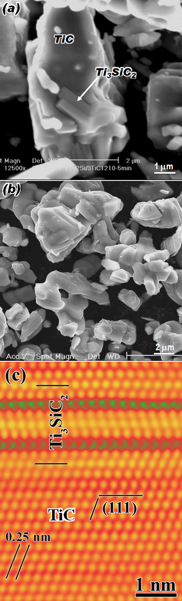
Ti3SiC2 powder synthesis
The MAX phase powders, registered as Maxthal 312 (Ti3SiC2) and Maxthal 211 (Ti2AlC), are commercially available, with the manufacturing information partly available in a patent.162
Heating of the Ti–Al–2TiC powder mixture at 1573–1473 K in flowing Ar for 15–30 min resulted in the production of 97 wt-%Ti3AlC2 powders, sized around 5 μm.163 However, when the elemental powders are heated, the mixture can be explosive. The latter was successfully suppressed by the addition of small amounts of Sn.164,165 Furthermore, the idea of reacting stoichiometric mixtures of Ti2AlC and TiC to synthesise Ti3AlC2 powders is an interesting alternate route for the MAX phase synthesis that needs further work, especially on the economics.166
Properties
Polymorphism
The early high pressure studies were performed on some MAX phases such as Ti3SiC2,167,168 Ti4AlN3,169 Ti2AlN and Ti3AlC2.168 Barsoum and co-workers168,169 were the first to report on polymorphic phase transformations in the MAX phases. They also investigated the behaviour of Ti3SiC2 at higher pressures.170 Further TEM171 and first-principles172 work confirmed these observations in Ti3SiC2. Ti3GeC2 was also found to show a transformation from α- to β-polymorph upon compression to 26·6 GPa, using a synchrotron radiation source.173
Polymorphism in the 211 and 312 phases can be traced to the various positions the A atoms in the unit cell can take; the M–X slabs remain unchanged.172 Polymorphism in the 413 phases is different. The more common structure is the α-structure of Ti4AlN3, where positions of the atoms along the c axis is AB
The issue of polymorphism in Ta4AlC3 is not that straight forward and sometimes controversial. In the very first report on Ta4AlC3, Manoun et al. 33 studied the high pressure behaviour of this compound by X-ray diffraction and found no phase transformation up to 47 GPa, assuming the α-polymorph. Discrepancies between measured and theoretical intensities were ascribed to preferred orientation. Experimental results on the structure of Ta4AlC3 were also reported by other groups that showed the structure to be β-Ta4AlC3.34,23
To account for the discrepency, Eklund et al. 36 for the first time, proposed the existence of two Ta4AlC3 polymorphs; Manoun et al. 33 and Etzkorn et al. 23 refined only the α-Ta4AlC3 structure, while Lin et al. 34 characterised β-Ta4AlC3. Eklund et al. 36 also supposed the structure reported by Manoun et al. 33 to be β-Ta4AlC3, with the evidence of close lattice parameters to the work of Lin et al. 34 However, thermodynamically, the existence of both α- and β-Ta4AlC3 at ambient conditions does not seem convincing.
To shed more light on this issue, Du et al. 39 studied the two polymorphs using first-principles calculations and showed that the total energy of α-Ta4AlC3 is ∼0·0866 Ry lower than that of β-Ta4AlC3, indicating that the α-polymorph is more stable (Fig. 4). The strong hybridisation between Ta1 5d and C1 2p, Ta2 5d and Al 3p in α-Ta4AlC3 result in the strong interaction between Ta1-C1 and Ta2-Al atoms, which stabilises the α-polymorph. Similar results were reported from different groups almost simultaneously.40,174,175
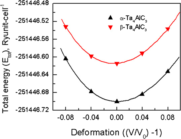
Total energy versus volume of α- and β-Ta4AlC3 (Ref. 39)
Furthermore, a thermodynamic study of Ta4AlC3,40 using first principles calculations confirmed that at temperature below 1875 K the α-polymorph is more stable, and above this critical temperature a transformation to β-Ta4AlC3 may occur. The other 413 phases studied, Ti4AlN3,40 V4AlC3,40 and Nb4AlC3,40,41 all show stable α-polymorphs at temperatures up to 3000 K.
Phase stability
Ti3SiC2 was reported to become unstable at different temperatures ranging from 1273 to 1673 K.176 – 181 However, Barsoum et al. 182 showed that Ti3SiC2 was thermodynamically stable up to at least 1873 K in vacuum for 24 h. They further argued that the reduced temperature at which Ti3SiC2 decomposed as observed by others was due to the presence of impurity phases in the starting powders.183
Ti3AlC2 was reported by Wang et al. 184 to be stable to at least 1744 K when heated in Ar with a low oxygen content. Selective oxidation of Al in Ti3AlC2 took place on top of the specimen, which resulted in the transformation of Ti3AlC2 into substoichiometric TiCx and Al2O3.
Good thermal stability was also reported in some bulk 211 phases, such as Ti2AlN,26 Ti2SC,61 and Ta2AlC,185 which were found to be stable at up to 1723, 1873 and 1873 K respectively.
In general, the thermal stability of the MAX phases depends on their constitutive elements, the atmosphere and the vapour pressure of the elements, particularly the A elements, such as Si and Al. For example, it has been shown that thin films decompose at lower temperature in comparison to their bulk counterparts, such as in Ti3SiC2,180,181,186 and Ti2AlN.187 This was attributed to the difference in diffusion length involved and possibly the measurement sensitivity used in the respective studies.180,181
It is worthwhile to mention the ‘Ti3SiC2 pest’ phenomenon.188 Ti3SiC2 was observed to undergo rapid and catastrophic disintegration above 1573 K in nitrogen, which was attributed to the volume change associated with the formation of mixtures of TiCx, Ti(C,N)x and TiN.188 A prevention process for such ‘Ti3SiC2 pest’ was suggested by increasing the oxygen partial pressure in the nitrogen atmosphere.
Electrical, thermal and elastic properties
The MAX phases are good electrical conductors, with reported room temperature resistivities ranging from 0·07 (Refs. 68 and 69) to 2 μΩ m.26 The low resistivities measured, for example, in Ti2SnC have been difficult to reproduce,68 which has been attributed to compositional variation and the presence of impurity phases in the microstructure;1 this value must therefore be treated with caution. As shown in Table 1, most of the MAX phases have lower resistivities than Ti metal (∼0·4 μΩ m). To date, the electrical conductivities of only around one-third of the reported MAX phases have been measured.
Yoo et al. 189 were the first to report on the negligible Seebeck coefficient or thermopower in Ti3SiC2 over the wide temperature range of 300–850 K. Later that range was extended to 5 K.94 The same is true of Ti3GeC2 and Ti3(Si,Ge)C2 solid solutions.94 This unusual phenomenon was found to be related to the anisotropy of the crystal structure.190 The components of the thermoelectric tensor of Ti3SiC2 and Ti3GeC2, but interestingly enough not Ti3AlC2, in the basal plane and along the c axis were found to have opposite signs.191 The near-zero thermopower of Ti3SiC2, Ti3GeC2 and most likely other MAX phases, suggests that these compounds could be useful as electrodes during thermopower measurements of other compounds.
The coefficients of thermal expansion of the MAX phases range from 7·2×10−6 to 13·3×10−6 K−1 (Table 1). Currently, the highest coefficients of thermal expansion were reported in Cr2AlC (Ref. 73) and Cr2GeC,57 which is one reason the former is a good candidate for large area coatings on steels.152 Measurements of the thermal expansion of the MAX phases in different orientations were performed using high temperature X-ray diffraction61 or synchrotron X-ray diffraction. For the most part, the MAX phases show little anisotropy in thermal expansion,61,192,193 usually with higher thermal expansions in the c than in a direction. The lower thermal expansion in a direction is apparently due to the stronger M–C bonding than the M–A bonding in the c direction.
The room temperature thermal conductivity data available to date for the MAX phases range from 12 to 60 W K−1 m−1. It is not surprising to find that the 413 compound Ti4AlN3, that shows the lowest electrical conductivity, shows the lowest thermal conductivity, due to the low carrier mobility which might be caused by the point defects in the crystal structure.194 The room temperature thermal conductivity of 60 W K−1 m−1,60 measured in Ti2SC is the highest to date, despite the fact that its electrical conductivity (1·92×106 Ω−1 m−1) is relatively poor.60 This is due to the large contribution from phonon channel in comparison to that of other MAX phases.60 A large phonon contribution to the thermal conductivity suggests a stiff material. This is consistent with the electronic structural study of Ti2SC.63 The stiffness, as represented by the high bulk modulus, was found to originate from the strong Ti 3d–S 2p hybridisation; the unusual strong M–A bonding in the MAX phases can also be seen from charge density maps as shown in Fig. 5.63
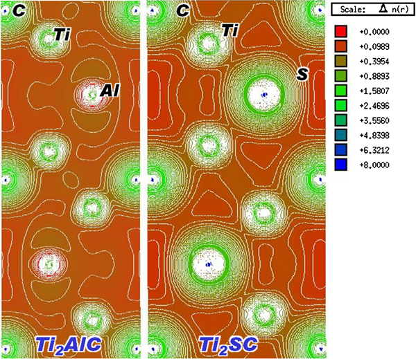
Calculated valence charge densities (eÅ−3) for (1120) plane of Ti2AlC and Ti2SC, revealing strong Ti–S interaction in Ti2SC (Ref. 63)
The MAX phases are characterised by high elastic constants, as represented by the Young’s modulus E and bulk modulus B. Values of E for MAX phases measured to date range from 178 GPa (Zr2SnC),68 to 340 GPa (Ti3GeC2),94 while B was found to range from 138 GPa (Cr2AlC),53 to 261 GPa (Ta4AlC3).33 The value of B for Ta4AlC3 was subsequently obtained as 198 GPa from the measured Young’s and shear moduli.35 This discrepancy could be due to the different experimental methods used in the two studies; a degree of uncertainty also exists over the polymorphic structure of the specimen used in the earlier study.
On the other hand, the highest stiffness value of the 211 phases measured to date is for Ti2SC (E = 316 GPa),61 almost equivalent to those of the stiffest 413 phases. This is, however, not due exclusively to the strong M–X bonds or a larger concentration of M–X bonds as in the 413 phases. Ti2SC has the smallest c/a ratio and consequently, exceptionally strong M–A bonds (Fig. 5) which contributes to the high stiffness.63 This bonding also accounts for its high thermal conductivity.60 However, several 211 phases, e.g. V2AlC,71 Nb2AlC,79 Nb2AsC,57 and Ta2AlC,79 show higher B values than that of Ti2SC. Experimental data for B show high scatter, particularly among data sets measured with different methods. Even higher discrepancies are common among B values calculated from first-principles.
These comments notwithstanding, the agreement between theory and experiment is quite good. One exception is Cr2AlC for which the discrepancy in the theoretical and experimental results, particularly in bulk modulus which is higher than usual. Schneider et al. 195 studied the elastic properties of Cr2AlC thin films by nanoindentation and ab initio molecular dynamics and reported the agreement between the experimental and theoretical results. The author and co-workers have found, however, that the interactions of the d-electrons in the density function theory, which have been so far ignored, play an important role in the elastic properties. The negligence of the Cr 3d on-site Coulomb energy, in the theoretical calculations, resulted in the overestimation of the bulk modulus of Cr2AlC.196 The revised values are more in line with experiment.71
Hardness, machinability, deformation and fracture
The reported data of the hardness of the MAX phases range from 1·4 to 8 GPa (Table 1). The low hardness, together with their layered nature, endows the MAX phases with probably their signature property, namely, excellent machinability. Figure 6 shows Ti3SiC2 samples fabricated using PDS and machined to various shapes either by lathe cutting, surface miller, electrical discharge machining and/or precision machining.2,8
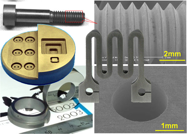
Ti3SiC2 fabricated with reactive PDS process and machined to different geometries8
The machinability of Ti2SC was successfully exploited in the development of Pb free free-cutting steels, as can be found in a publication in Japanese197 and some patents. In the metallurgical literature, Ti2SC is usually referred to as Ti4C2S2, since it has long been found as an inclusion phase in steels and superalloys.198 – 200 The strain induced precipitation of Ti2SC and its possible self-lubricating properties199,200 are fruitful areas of the study of other MAX phases. It is interesting to note that Ti2SC is the hardest among the MAX phases reported to date and also possesses the highest stiffness (Table 1). With the success of Ti2SC as a free-cutting element in steels and the fact that other MAX phases are softer, one is greatly encouraged to develop more such free-cutting MAX phases to replace Pb in free-cutting stainless steels and even in most brasses, to eliminate the harmful effects of Pb on the environment.201,202
Basal plane slip in the crystal structures of the MAX phases enables dislocation activity, and hence local plastic deformation, even at room temperature. Figure 7 shows the slip lines observed on the surface of the Ti3SiC2 sample surface near a Vickers hardness indentation made at room temperature.2 These slip lines resemble those observed on the surface of deformed metal samples. It is this microplasticity, together with its good thermal conductivity, that is mostly responsible for the good thermal shock resistance of the MAX phases. For example, quenching polycrystalline Ti3SiC2 samples from 1673 K into water did not affect their post-quench flexural strengths.105 The microplasticity is also responsible for the remarkable damage tolerance of the MAX phases, such as reported for Ti3SiC2,203 Ti3AlC2,91 Ti2SnC,204 Ta2AlC,54 Cr2AlC,74 Ta4AlC3,35 Nb2AlC,80 Ti4AlC3,26 and others.
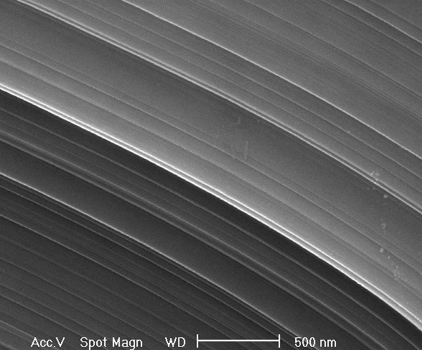
Room temperature plastic deformation in Ti3SiC2 grain2
Like conventional ceramics, the MAX phases have higher compressive,205 than tensile206,207 or flexural strengths.208 Figure 8 shows the deformation and strength of Ti3SiC2 tested under compression and four-point bending conditions at various temperatures and the samples after deformation.2 Compressive strengths as high as 1·9 GPa have been reported for some MAX phases.65
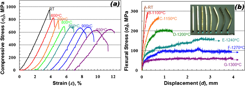
Mechanical properties of Ti3SiC2 prepared by reactive PDS process
The concept of incipient kink bands was proposed by Barsoum et al. 209,210 to understand the reversible non-linear elastic deformation in polycrystalline Ti3SiC2 subjected to cyclic loading. When Ti3SiC2, and other MAX phases were studied in the porous form, higher absolute energies were dissipated.7,211 Since kinking is a form of plastic buckling, the lack of constraint, due to the presence of the pores must facilitate the formation of more incipient and regular kink bands, which in turn lead to higher energies dissipated per volume.7 Some results are shown in Fig. 9.7,209,210 Along this line, an increase in porosity reduces the threshold stresses needed for incipient kink band formation.7,212
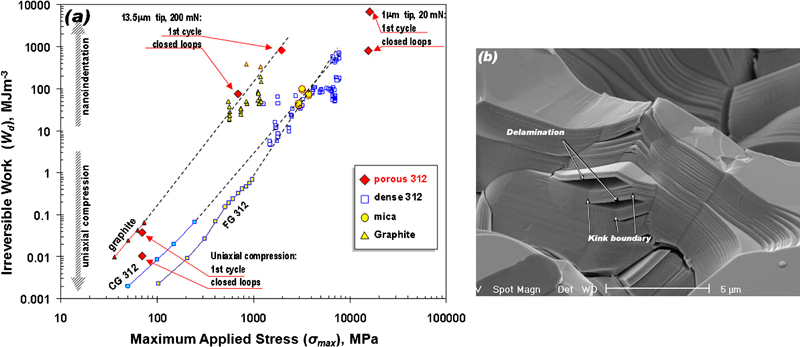
a summary of energy dissipation data, in the form of a logarithm correlation between the irreversible work and the applied maximum stress, of recently investigated kinking nonlinear elastic solids,209,210 including the results for a 43% porous Ti3SiC2,7 and b the underlining mechanism revealed by kink band formation and concomitant delamination of a solid bridge between pores in Ti3SiC2 (Ref. 7)
The fracture toughness K IC values of the MAX phases range from 4·5 to 16 MPa m1/2 for Ti3SiC2,106,213 – 219 and from 4·6 to 9·1 MPa m1/2 for Ti3AlC2.93,118,220 The K IC values mainly depend on microstructure; generally coarse grained microstructures result in higher K IC values due to the deflection and delamination of cracks by single grains. These mechanisms result in a profusion of crack bridging processes in the crack wake (Fig. 10a ).218 This ligament is essentially one that is held together by strong Ti–C bonds. This micrograph is very reminiscent of typical ligaments seen in wood.
a lamellae bridge observed in crack wake of coarse grained Ti3SiC2 in R curve measurement218 and b 8 inch Ti2AlC block indented by steel hammer (courtesy of 3-ONE-2, LLC)
The fracture toughness values of some other MAX phases were also reported in similar range, e.g. Nb4AlC3 (7·1 MPa m1/2),42 Ta4AlC3 (7·7 MPa m1/2),35 Ta2AlC (7·7 MPa m1/2),54 Ti2AlC (6·5 MPa m1/2),221 etc.
The good fracture toughness and the microplasticity results in behaviour that is very reminiscent to that of metals, as evidenced in Fig. 10b , where the surface of an 8×4 inch Ti2AlC block was repeatedly hit with a heavy steel hammer. The latter only caused the formation of surface dents.
Fatigue and creep
The fatigue behaviour of MAX phases have been reported only in Ti3SiC2,216,218,222 which exhibits cyclic fatigue crack propagation behaviour similar to typical structural ceramics, i.e. a much larger dependence of crack growth rates on K max, as compared to ΔK (Fig. 11).222 Nevertheless, Ti3SiC2 is characterised by higher threshold stress intensity factors and lower crack growth rates, that are superior to conventional structural ceramics.222 The high fatigue resistance originates from the heterogeneous and laminated structure. The fatigue threshold ΔK th of Ti3SiC2 was found to remain essentially unchanged between 298 and 1373 K;216 however, at 1473 K there was a sharp decrease in ΔK th, due to the formation of a large number of deformation microcracks. The crack tip shielding was found to result from both the bridging of entire grains and from deformation kinking and bridging of microlamellae within grains.
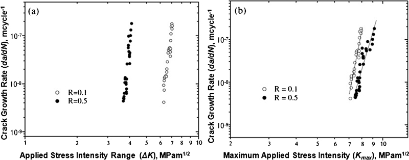
Relationship between crack growth rates da/dN and a applied stress intensity range ΔK and b maximum applied stress intensity K max, for Ti3SiC2 at load ratios R of 0·1 and 0·5 (Ref. 222)
Similarly, the creep behaviour of MAX phases has been also mainly reported in Ti3SiC2.223 – 225 Tensile creep tests performed on fine and coarse grained Ti3SiC2 microstructures in the 1273–1473 K temperature range showed primary, secondary and tertiary creep regimes.223,224 In compression, Zhen et al. 225 reported that the creep behaviour of Ti3SiC2 is also characterised by three regimes. The stress exponents of ∼2, in the quasi-steady state regime were comparable to those measured in tension. The creep rates in compression, however, were roughly an order of magnitude lower than in tension. With an increase either in stress and/or in temperature, a change of mechanism from dislocation creep to possibly subcritical crack growth was proposed.
With the potential use of the MAX phases as structural materials for high temperature applications, the investigation into their creep behaviour is urgently needed.
Oxidation
The oxidation of Ti3SiC2 in the form of powder176 or bulk226 – 229 has been studied and the oxidation kinetics was reported to be parabolic during exposure at 1173–1673 K.226 The oxidation rate was found to be lower than that of TiC, with oxides of TiO2 and SiO2 formed.176 The oxidation occurs by the outward diffusion of Ti and C and the inward diffusion of oxygen.226
A thin SiO2 rich scale was found to form on the surface of Ti3SiC2 after short term oxidation at 1273 K in air.227 It is important to note, however, that long term oxidation, of Ti3SiC2 has shown that after ∼100 h, the oxidation kinetics revert from parabolic to linear and that the highest temperature continuous use temperature of Ti3SiC2 is probably 1173 K. The reason for the change in mechanism is not fully understood, but could be due to the formation of microcracks in the rutile outermost layer.230
Anomalous oxidation with higher kinetics at lower temperatures was observed in Ti3SiC2 when tested at 773–1073 K in flowing dry air.231 This phenomenon was believed to result from the formation of microcracks in the oxide scales due to phase changes in the oxide products. If this phenomenon is ubiquitous then it should be carefully examined. However, the authors have argued that will not be a serious problem in practice since any cracks formed were partially filled with amorphous SiO2. This is especially true in Ti3AlC2 given the crack healing abilities of Ti3AlC2 at least during the early stages of oxidation.232
In general, Ti3AlC2 has much better oxidation resistance than Ti3SiC2. A comparison of the oxidation kinetics shows that the parabolic rate constants of Ti3SiC2, at the same temperatures, were 2–4 orders of magnitude greater than those of Ti3AlC2.93,233 The superior oxidation resistance is attributed to the formation of an adherent, continuous inner Al2O3 layer, which forms below an outer TiO2 layer.233 The adherent, high integrity Ti3AlC2/Al2O3 interface was confirmed by high resolution TEM study (Fig. 12).234
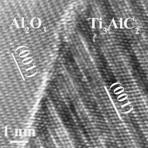
High resolution TEM image of Ti3AlC2/Al2O3 interface formed after oxidation at 1473 K for 8 h (Ref. 234)
Similarly, Ti2AlC was found to be exceptionally oxidation resistant, because it forms a stable and adherent protective Al2O3 scale.235 The performance up to 1848 K, was evaluated in vacuum levels down to 10−2 Pa. Ti2AlC showed a parabolic and stable oxide growth rate up to 1673 K in air. Cyclic testing confirmed that the oxide layer is adherent to the bulk.235
The oxidation mechanism in Cr2AlC, when investigated in 1373–1523 K temperature range, was also found to be by the outward diffusion of Al, together with small amounts of Cr, and the inward diffusion of O to form a surface layer of α-Al2O3. Here, carbides (Cr7C3 and Cr3C2), rather than oxides, formed in a layer under the outermost oxide layer. The oxidation of Cr2AlC also obeyed a parabolic rate law,236,237 with the parabolic rate constants tabulated in Table 2. Comparison with two representative 312 phases indicate that Cr2AlC shows comparable or superior oxidation resistance with Ti3AlC2 and much better oxidation resistance than Ti3SiC2.
Parabolic oxidation rate constants of some typical MAX phases
Corrosion
The corrosion resistance of Ti3SiC2 in acid or alkaline solutions240,241 has been found in some instances to be better than that of pure Ti.241 The enhanced resistance was attributed to the formation of a thin, passivating SiO2 based layer. Passivating layers were also found to be responsible for the good corrosion resistance of Ti3GeC2 and Ti2AlN.242 The electrochemical corrosion behaviour of more MAX phases has been studied in NaOH, HCl and H2SO4 solutions.243 Active dissolution or passivation was observed, depending on the solutions and potentials applied, but a generalised corrosion resistance diagram for the MAX phases is still lacking.
Ti3SiC2 was found to suffer from serious hot corrosion at temperatures above ∼1123 K when coated with or immersed in Na2SO4.244 – 246 The mass gains during the hot corrosion were greater than those of specimens oxidised in air at the same temperatures.244
By contrast, Cr2AlC was found to exhibit exceptionally good hot corrosion resistance against molten Na2SO4.247,248 The parabolic rate constant for the hot corrosion of Na2SO4 coated Cr2AlC at 1273 K was 3·4×10−11 kg2 m−4 s−1.247 The corrosion resistance was attributed to the formation of a protective Al2O3 rich scale.
In line with its excellent oxidation resistance, Ti2AlC was found to exhibit good corrosion resistance in Na2SO4.249 A protective continuous Al2O3 layer was formed that imparted good corrosion resistance; consequently, the corrosion kinetics was generally parabolic at 1123 K. However, the porous oxide scale failed to protect the Ti2AlC substrate at 1173 and 1273 K.
In view of potential applications in contact with molten metals, Ti2AlC and Ti3SiC2 were tested for corrosion in circulating molten Pb at 923 and 1073 K. The extent of reaction was minimal for both materials.250 However, molten Al was found to react with Ti3SiC2 to form interconnected networks of TiC0·67 and molten Al.251
Friction and wear
Tribological studies have to date concentrated on Ti3SiC2, which was initially expected to be a material with ultra low friction, based on an early experimental report that the friction coefficient μ, measured on cleaved basal planes of individual grains, was 0·0025.252 When sputtered Ti3SiC2(0001) thin films were measured at normal loads of 0·1 mN to 0·24 N; however, μ of 0·1 and 0·8 were obtained for low and high applied loads respectively.253 The high friction and fast wear were attributed to excessive debris resulting in third-body abrasion.
Two stage friction and wear behaviour was reported in Ti3SiC2,254 – 256 and Ti3AlC2, as well as its composites,257 when tested against various counterparts. For example, El-Raghy et al. 254 found that the friction of Ti3SiC2, either coarse or fine grained, against a steel always underwent an initial transition period with μ of 0·15–0·45 followed by a static period with a μ of ∼0·8. The transition from the first stage to the second stage, with higher μ values and wear, was attributed to debris accumulation.254,257
Self-lubricating properties of Ti3SiC2 were reported against an oscillating diamond pin (μ = 0·05–0·1), but not against Ti3SiC2 itself.258 The low μ values of Ti3SiC2 against diamond were attributed to the formation of a thin film on the Ti3SiC2 tribosurface.
The wear rates reported for the MAX phases are usually in the order of 10−5 mm3 N−1 m−1 or higher,254,259 – 261 which is considered to be higher than the wear rate tolerable in service, i.e. 10−6 mm3 N−1 m−1. Exceptionally low wear rates were reported for Ti3AlC2 (∼2×10⁻⁶ mm3 N−1 m−1),262 Ta2AlC and Ti2AlC (⩽1×10⁻⁶ mm3 N−1 m−1).261 Attempts have been made to develop wear resistant composites by incorporating hard particles such as SiC,263 or Al2O3,257,264 into the MAX matrix. This approach was found to be effective in reducing the wear rate.
Other surface phenomena
Spontaneous growth of whiskers from a MAX phase was first reported in 1999, where Ga whiskers were observed to ‘self-extrude’ from Cr2GaN bulk samples. Initially, it was postulated that the basal planes of Cr2GaN were the Ga source.265 Shortly thereafter, it was postulated that the actual Ga source was excess, or unreacted, Ga present at the grain boundaries.266 Similar phenomena have also been reported in Zr2InC,267 and in a Ti–Sn–C system.268 The driving force for the room temperature spontaneous growth of low melting point metal whiskers was attributed to the diffusion of oxygen into the grain boundaries of the substrate from which the whiskers were sprouting.267
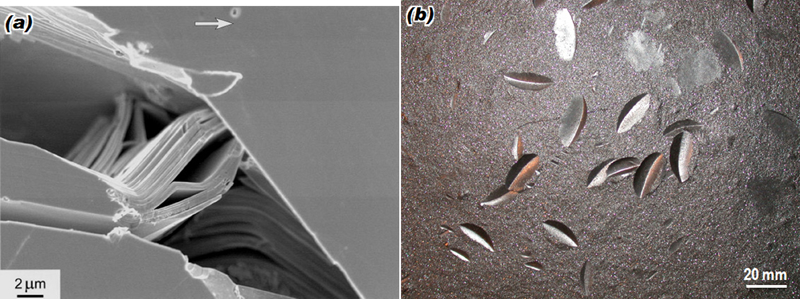
However, the room temperature spontaneous Ga whisker growth from Cr2GaC,269,270 could not be explained by any of the proposed mechanisms. Instead of being extruded from the grain boundaries of the Cr2GaC, Ga whiskers were observed to grow from freshly cleaved basal planes from near surface grains. More convincing observations were made on the fracture surface of a Cr2GaC sample, where a huge (in comparison to the grain it grew from) Ga whisker grew from the basal plane of a fractured grain (Fig. 13).269 Given that the basal plane on the fracture surface is unconstrained, mechanisms employing stress and extrusion cannot be responsible. Instead, mechanisms such as solidification (the melting point of Ga is near room temperature), and/or recrystallisation may have to be considered to explain this phenomenon. Interestingly, room temperature spontaneous growth of Ga freestanding nanoribbons from Cr2GaC surfaces was also observed.270,271 Future work on these aspects are required to further understanding of such phenomena.
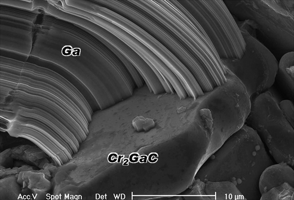
Ga whisker observed on basal plane of a Cr2GaC grain on fracture surface: whisker growth axis measured to be Ga[010] (Ref. 269)
After creep failure at 1573 K, silica based nanofibres with diameters of ∼250 nm and lengths of up to a few tens of micrometres were observed on the fracture surfaces of Ti3SiC2.272 The formation of a silicon oxide layer immediately after creep failure and their subsequent elongation and tearing in the crack wake was postulated to be the mechanism for the formation of these fibres. Later, synthesis of AlN nanowires by the nitridation of Ti3Si0·9Al0·1C2 solid solution was reported.273 Single crystalline AlN nanowires with the hexagonal wurtzite structure were easily prepared. These reports imply that the MAX phases are promising raw reactants for the synthesis of various one- and two-dimensional nanostructures of nitrides and oxides.
Materials and processes based on MAX phases
Surface technology
Surface modification
Owing to its several attractive properties, Ti3SiC2 has been considered for high temperature applications. However, compared with traditional binary carbides, its hardness and wear resistance are low. A useful approach in order to enhance the latter while maintaining the attractive properties is surface modification or the application of hard coatings.
To enhance the surface hardness, El-Raghy and Barsoum274 carburised Ti3SiC2 surfaces and increased the hardness from 4 GPa to 20–25 GPa. Meanwhile, silicidation of Ti3SiC2 enhanced the high temperature oxidation resistance by about three orders of magnitude.274 Surface boronising for Ti3SiC2 increased the hardness from 3·7 GPa to a maximum of 9·3 GPa.275
During the work of surface carburisation, sicilidation, composite and joining processes, Ti3SiC2 was found to transform to TiC by the de-intercalation of Si from the structure when the Ti3SiC2 is in contact with Cu,276 Ni,277 graphite,274 molten cryolite186 and liquid Al.251 Stimulated by these findings, Guo et al. 278 deposited a Cu film on Ti3SiC2 by magnetron sputtering followed by annealing in the 1173–1373 K temperature range. Owing to the formation of TiC, the surface hardness increased from ∼5 GPa to a maximum of ∼10 GPa, depending on the relative amount of TiC, which was controlled by the Cu film thickness.
Wan et al. 279 fabricated a hard–soft–hard sandwich structure of Al2O3–Ti3SiC2–Al2O3, and found the maximum strength to be 14·5% higher than that of the monolithic Ti3SiC2. The strong Al2O3/Ti3SiC2 interface was attributed to the formation of Si and Ti–Si liquid phases and their penetration into the Al2O3 layers.280
Diamond on Ti3SiC2
Diamond nucleation on non-diamond surfaces without pretreatment is reported to be difficult and slow. By enhancing the nucleation kinetics, such as scratching, nucleation densities of 108 cm−2 can be obtained on Si and carbide forming refractory metals, such as Nb, Mo and Ti. It has been found that a carbide interlayer is initially formed on these substrates, before diamond nucleation, such as SiC on Si, Mo2C on Mo and TiC on Ti (e.g. Refs. 281 and 282).
On the surface of a Ti3SiC2 ample fabricated via the reactive PDS process, Yang et al. 282 investigated the diamond nucleation and growth by microwave plasma enhanced chemical vapour deposition. A much higher diamond nucleation density, and consequently, much higher film growth rates were obtained on Ti3SiC2 as compared to Si wafers. Furthermore, the diamond films on Ti3SiC2 were smoother with a preferred [0001] orientation and exhibited better adhesion than those on Si.282
In general, nanocrystalline diamond (NCD) films have several advantages over microcrystalline diamond (MCD) films. The high diamond nucleation density on Ti3SiC2 is thus a great advantage for the synthesis of NCD films. NCD films were synthesised on Ti3SiC2 by MPCVD under typical conditions for MCD synthesis.283 A diamond nucleation density of 1011 cm−2 was achieved and consequently dense NCD thin films with an average grain size of ∼30 nm (Fig. 14) and film growth rates of ∼2 μm h−1 were obtained. Cross-sectional SEM images showed NCD films with an equiaxed grain structure and a dense film/substrate interface.
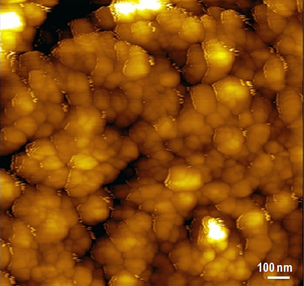
Atomic force microcopy image of surface of Ti3SiC2 after 20 min diamond deposition283
Diamond thin films of ∼10 μm thick were also successfully deposited onto Ti3SiC2 with different geometries.284 The diamond coated surfaces of all specimens were polished up to a surface roughness of ∼0·2 μm. Friction coefficients between the polished diamond plate and a stainless steel rail, the plate specimen, and between a rotating rod and a stationary outer ring, were measured, and the lowest friction coefficients in both specimens were <0·01.284
It thus appears that Ti3SiC2 is an excellent heterosubstrate for diamond nucleation and growth. Furthermore, it can be readily machined to complicated components before the deposition. Once an adhesive diamond thin film is successfully deposited on it, the applications of diamond thin films can be greatly expanded. In the meantime, deposition of a diamond film on the surface of Ti3SiC2 would be of great importance to improve its tribological properties.
Joining
To further extend the application of the MAX phases to more complicated and larger dimensions, joining of the MAX phases, mainly of Ti3SiC2, has been investigated.
Gao et al. 285 carried out diffusion bonding for joining a Ti3SiC2 with a Ti–6Al–4V alloy and found the reaction was rate controlled by the solid state diffusion below 1623 K. The strength of such processed joint, however, is quite low, with a value of 100 MPa, which was attributed to the tensile stresses developed in the Ti5SiCx single layer.
Hashimoto et al. 286 employed slurry spin coating and reactive sintering techniques for joining Ti3SiC2. Slurries of Ti, Si and TiC powders were spin coated on Ti3SiC2 test pieces under various conditions. The coated pieces were joined together and sintered, under pressure, at temperatures of 1523–1573 K. The bonding layers were 20 or 30 μm thick and showed finer grain size than those farther from the interface.
Yin et al. 277 studied the diffusion bonding of Ti3SiC2 and Ni and found the growth of the reaction layer to follow a parabolic law. The diffusion of nickel through the reaction zone toward Ti3SiC2 was found to be the main controlling step in the bonding process. Joint strengths were measured with shear tests and showed maximum shear strengths of the order of 121 MPa, a value believed to be close to that of bulk Ti3SiC2.
MAX phases with similar constituent elements, such as Ti3SiC2–Ti3GeC2 and Ti2AlC–Nb2AlC, were found to form solid solution at interfaces by interdiffusion.287 This interdiffusion also enabled the bonding of Ti3SiC2 via Al interlayers,288 or bonding Ti3AlC2 via Si interlayers.289 In both cases, diffusion of the interlayer element into the MAX phases led to the formation of Ti3(Si,Al)C2 solid solutions rather than intermetallic compounds. Flexural strength reached about 65 and 80% for the Ti3SiC2 joint with Al interlayers and the Ti3AlC2 with Si interlayers of their respective monolithic MAX phases. Direct bonding of Ti3SiC2 and Ti3AlC2 by interdiffusion is also possible. The resulting bonding strengths are slightly lower than those made using interlayers.290
It is worth noting that with good machinability, parts made of MAX phases can be easily joined by mechanical methods such as threading, flanging, etc. in addition to the bonding processes discussed above.
Composites
MAX–MX and MAX–AX
Since SiC and TiC are thermodynamically stable with Ti3SiC2, and SiC has excellent oxidation resistance, Ti3SiC2–SiC and Ti3SiC2–TiC were the early MAX based composites synthesised and investigated.291 – 293 Tong et al. 291 found higher flexural strengths in Ti3SiC2–20SiC–8TiC (vol.-%) composite than monolithic Ti3SiC2, particularly at high temperatures. The fracture toughness, however, was reduced. This was attributed to a lack of large grains in the composite microstructure. The hardness was measured to be 9 GPa, a value that is close to that reported by Radhakrishnan et al. 292 for a Ti3SiC2–14 vol.-%SiC composite.
In the study of two composites, Ti3SiC2–30SiC and Ti3SiC2–30TiC (vol.-%),293 both TiC and SiC were found to lower grain boundary mobility in Ti3SiC2. At comparable grain sizes, all composites tested were weaker in flexure than the unreinforced Ti3SiC2 matrix, with the reduction in strength being the worst for the SiC composites, which was attributed to thermal expansion mismatches between the matrix and reinforcement phases. The composite samples, however, were exceptionally damage tolerant and thermal shock resistant.
Incorporating secondary phases into the MAX phase microstructure usually aims at strengthening the compound. However, the unique properties of the MAX phases can also be utilised as a binder phase for hard metals. For example, hard alloys for cutting tools and moulds, based on WC, are vital for the manufacturing industry. However, W is a rare metal. Therefore, there is a demand, particularly in Japan, for elements that can replace W. TiC is a carbide with better hardness than WC and is a good candidate in replacing WC in hard alloys. There have been some attempts for using TiC–Ni, cermets, as a substitute for W. This approach today, has not been widely accepted partially because Ni is also a relatively rare element and the properties of such cermets are not satisfactory yet.
Sun and co-workers synthesised Ti3SiC2 using TiC in the starting materials (e.g. Refs. 107, 112 and 114), and this motivated the in situ synthesis of TiC–Ti3SiC2 composites by adjusting the ratio of TiC in the starting powders. Better interface structures were expected in the composites synthesised via this route. TiC–Ti3SiC2 composites294,295 were synthesised by an in situ reactive PDS process. The strengths of the composites was increased by the incorporation of Ti3SiC2 and a maximum strength was achieved at ∼50 vol.-%Ti3SiC2. The grain size of the Ti3SiC2 phase was still relatively coarse (Fig. 15). Processes which produce composites with finer Ti3SiC2 grains may result in better materials. Processes such as MA followed by HP296 and a newly developed travelling zone sintering method297 were also employed for the TiC–Ti3SiC2 composites.
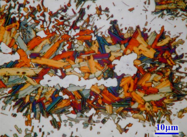
Microstructure of TiC–55 vol.-%Ti3SiC2 composite294
Toughening SiC with Ti3SiC2 dispersions was also investigated.298 The addition of Ti3SiC2 to SiC led to improved fracture toughness, with the best combination of properties obtained to be a K IC = 8·3 MPa m1/2 and an HV = 17·6 GPa. Conversely, it is possible to reach a combination of hardness and fracture toughness by controlling the decomposition of Ti3SiC2 to various binary carbides.
Much less information on Ti3AlC2 based composites is available in the literature. Starting with Ti3AlC2 powders and microsized SiC and ZrO2, a Ti3AlC2 composite was synthesised.299 Both the Ti3AlC2–SiC and Ti3AlC2–ZrO2 composites were superior to the monolithic Ti3AlC2 in strength, fracture toughness, and microhardness.
MAX–oxide
Luo et al. 300 fabricated Al2O3–Ti3SiC2 composites with a full range of volume fractions, by attrition milling the Al2O3 and Ti3SiC2 powder mixtures followed by an spark plasma sintering process. The hardness decreased with increasing of Ti3SiC2 content, while the fracture toughness and the strength increased. It is interesting to note that the sample without Al2O3 showed the maximum flexural strength (673 MPa) and the maximum toughness (9·3 MPa m1/2), which is relatively high for monolithic Ti3SiC2. A small amount of TiC was found in the microstructures and that was attributed to the reaction of carbon in the furnace with the Ti3SiC2. However, according to the experience of this review’s author, ball milling involved in the fabrication process may have a considerable effect on the formation of ancillary phases such as TiC. In the composites with Ti3SiC2 as matrix and up to 20 vol.-%Al2O3 as reinforcement,301 that was in situ synthesised from mixtures of reactant powders, the hardness increased considerably, while the dependency of strength and fracture toughness were generally in agreement with previous results300 though the absolute values are much lower.
Using a similar process,300 Pan et al. 302 fabricated Ti3SiC2–TZP composites with up to 50 vol.-%Ti3SiC2. While the Vickers hardness values and flexural strengths of the composites decreased with increasing Ti3SiC2 content, the fracture toughness increased. The maximum fracture toughness of ∼10 MPa m1/2 was achieved for the composite with 50 vol.-%Ti3SiC2. The dielectric behaviour of Ti3SiC2–TZP composites was also reported.303
Composites of Ti3AlC2, with up to 20 vol.-%Al2O3, were fabricated by reactive sintering.304 The strengths, hardness and toughness values are enhanced by the incorporation of Al2O3. The strengthening and toughening effects were attributed to possible compressive residual stresses at the interfaces, a conjecture that may need more confirmation. When the composite with the optimal Al2O3 content (10 vol.-%) was tested at high temperatures, the strengthening effect caused by Al2O3 strongly depended on the mode of failure.305 The dielectric properties and the electromagnetic interference shielding effect of Ti3SiC2–Al2O3 composites were also reported.306,307
Combustion reaction of TiO2–Al–C at ∼1173 K leads to Ti3AlC2–TiC–Al2O3 composites.308 Vickers hardness, fracture toughness, and flexural strength of the nearly dense sample synthesised from 3TiO2–5Al–2C were measured to be 13·3 GPa, 5·8 MPa m1/2 and 466 MPa respectively. This process, starting from low cost raw materials such as TiO2, should be pursued more vigorously since it may prove to be a low cost method for the synthesis of MAX phases.
It is interesting to note a report on a three-dimensional printing process developed for the multiphase composite of Ti3AlC2–TiAl3–Al2O3.309
MAX–boride
Cubic boron nitride (cBN) is the second hardest material next to diamond. Benko et al. 310 fabricated cBN–Ti3SiC2 composites and observed various phases such as TiB2, SiC4, TiC and SiC at the cBN/Ti3SiC2 interfaces.
TiB2 also shows high hardness, modulus, low density, excellent chemical inertness, high electrical conductivity (5×10⁷–10×107 Ω−1 m−1) and a coefficient of thermal expansion close to Ti3AlC2, that makes it a good reinforcement for Ti3AlC2. For example, the maximum compressive and flexural strengths of Ti3AlC2–TiB2 composites were measured to be 2·2 GPa and 861 MPa respectively,311 in contrast to the respect values of monolithic Ti3AlC2 of 723 and 340 MPa. The strengthening effect was operational at least up to 1373 K. Contribution in electrical conductivity from TiB2 was also observed.
MAX–metal
Via a powder metallurgy route, Zhang et al. 312,313 fabricated a Cu matrix composite reinforced by Ti3SiC2 particulates, aiming at improving the mechanical properties, without seriously decreasing the conductivity, for potential application as new electrofriction materials. The Cu–Ti3SiC2 composites showed superior mechanical properties over Cu–graphite composites. At filler contents of <20 vol.-%, the electrical conductivity for Cu–Ti3SiC2 composites was higher than that for Cu–graphite composites. At higher filler contents, however, the electrical conductivity for Cu–Ti3SiC2 composites was lower than that for Cu/graphite composites because of the presence of residual pores. Resembling Cu–graphite composites, the Cu–Ti3SiC2 was also found to be self-lubricant.
At high volume fractions of Ti3SiC2, however, densification of Cu–Ti3SiC2 composites became difficult.314 To solve this problem, Ti3SiC2 particulates were coated with a layer of Cu by an electroless plating method.315 The coated layer of Cu prevented direct contact and agglomeration of the Ti3SiC2 particulates. The composite reinforced with Cu coated Ti3SiC2 exhibited higher density and homogeneous distribution of Ti3SiC2 in the Cu matrix, and hence improved mechanical properties at ambient and elevated temperatures.314
Peng220 fabricated Cu–Ti3AlC2 composites and found that Ti3AlC2 increased the strength of Cu considerably. Unfortunately, the electrical conductivity was reduced by two orders of magnitude in comparison with the Cu matrix.220,316
Ti2SnC was reported to show the highest electrical conductivity (14×106 Ω−1 m−1),69 among the MAX phases (Table 1), and thus also employed as a reinforcement for strengthening Cu.317 – 319 The interfacial reaction between Cu and Ti2SnC was observed to be controlled by the de-intercalation of Sn from Ti2SnC to form Cu(Sn) solid solutions and TiCx.317 The Cu grain size was significantly decreased by incorporating the Ti2SnC dispersion. Consequently, the yield strengths were enhanced by a factor of four over those of pure Cu.319 The most encouraging result is that the conductivity of the composite was 85·6% of pure Cu.319 The friction coefficients and wear rates of the Cu matrix composites were found to decrease significantly by the incorporation of the Ti2SnC particles. For example, the wear rate of a Cu–10 vol.-%Ti2SnC composite was only one-eighth of pure Cu.318 It thus appears that, to date, Ti2SnC is the best possible MAX phases reinforcement for Cu as far as mechanical and electrical properties are concerned.
MAX composites for biomaterials
Hydroxyapatite has biological properties of great interest for osteo-implantation. However, its poor mechanical properties restrict its application. Considering the bioinertness of Ti3SiC2,320 Shi et al. 321 fabricated Ti3SiC2–hydroxyapatite composites with different Ti3SiC2 volume fractions. The composite’s flexural strengths and fracture toughness values increased with increasing Ti3SiC2 content, up to 252 MPa and 3·9 MPa m1/2 respectively, at 50 vol.-%Ti3SiC2. On the other hand, the Vickers hardness decreased with Ti3SiC2 content, which favours bio-applications. The composites are machinable when the Ti3SiC2 content is >20 vol.-%.322
Carbide derived carbon (CDC)
Nanoporous CDC structures have been produced by selectively etching metal atoms from metal carbides.323 The fact that the porosity of CDC can be accurately controlled for specific postulated end uses has led to much effort to determine the effects of pore size, volume, and surface area on transport and adsorption properties. The tailored properties that can be achieved in CDC have facilitated advances in demanding applications such as hydrogen storage, supercapacitors and devices for treatment of sepsis extracorporeally (i.e. sorption of biomolecules).323
Beside processes based on binary carbides as the precursors, CDCs have also been synthesised through chlorination of carbon and nitrogen containing MAX phases at elevated temperatures.324 – 327 Gogotsi et al. 324 studied CDC formation from Ti3SiC2 powders and bulk samples as a function of synthesis temperature. Etching of Ti3SiC2 led to a larger pore volume (∼75%) compared with TiC (56·2%) or SiC (57·3%). Chlorination in a flow of pure Cl2 for 3 h in a quartz tube furnace resulted in the extraction of Ti and Si from Ti3SiC2 leading to the formation of C by the reaction of Ti3SiC2+8Cl2 (g) = SiCl4 (g)+3TiCl4 (g)+2C. Carbide derived carbons derived from Ti3SiC2 have a theoretical density of 0·55 g cm−3.
Carbide derived carbons synthesised starting with Ti2AlC powders via chlorination have structures that are primarily amorphous when the chlorination temperature is low.325 Graphitic ribbons, as well as sharply bent graphitic structures, were observed at 1073 K. As the chlorination temperature was further increased to 1273 K, the width of the graphitic ribbon increased. No significant increase in graphitisation occurred between 1273 and 1473 K. Sorption measurements determined the presence of micropores (0·40–2·0 nm) after chlorination at 673 K; chlorination at 1073 K or higher resulted in both micro- and mesopores (0·35 to >7 nm).325
A systematic characterisation was carried out for both the micro- and mesoporosity, that developed when Ti3SiC2, Ti3AlC2, Ti2AlC, Ti2AlC0·5N0·5, Ta2AlC, as well as two binary carbides of Ta2C and TaC were chlorinated at different temperatures.323 The CDCs’ porosity depended on the initial carbide’s structure and chemistry. Carbides with anisotropic structures, such as the MAX phases, resulted in larger mesopore volumes as compared to more isotropic carbides such as TaC. Furthermore, the carbon pore structure can collapse, resulting in low pore volumes, for materials with very low molar fractions of carbon, as was the case with Ti2AlC0·5N0·5.
Applications
Reviewing the properties of the MAX phases in 2000, Barsoum1 listed potential applications as including substitution for machinable ceramics, kiln furniture, wear and corrosion protection, heat exchangers, applications where rotating parts are used, low friction applications based on basal plane lubricity.
El-Raghy and Barsoum founded the company 3-ONE-2, LLC, apparently after the 312 phases, in 2001 as a joint venture with Kanthal AB (a Sandvik subsidiary). Since then, Maxthal 312 (Ti3SiC2) and Maxthal 211 (Ti2AlC) have been commercialised in the form of powders and fully dense parts. Currently the full scale pilot plant is capable of producing batches of >100 kg of −325 mesh powders of Ti3SiC2 and Ti2AlC.
Beside the commercialisation of the Maxthal powders, heating elements made of Maxthal 211 were developed (Fig. 16a ), and this was extended to the novel high temperature reactors for in situ X-ray absorption spectroscopy measurements in fluorescence (Fig. 16b ).328
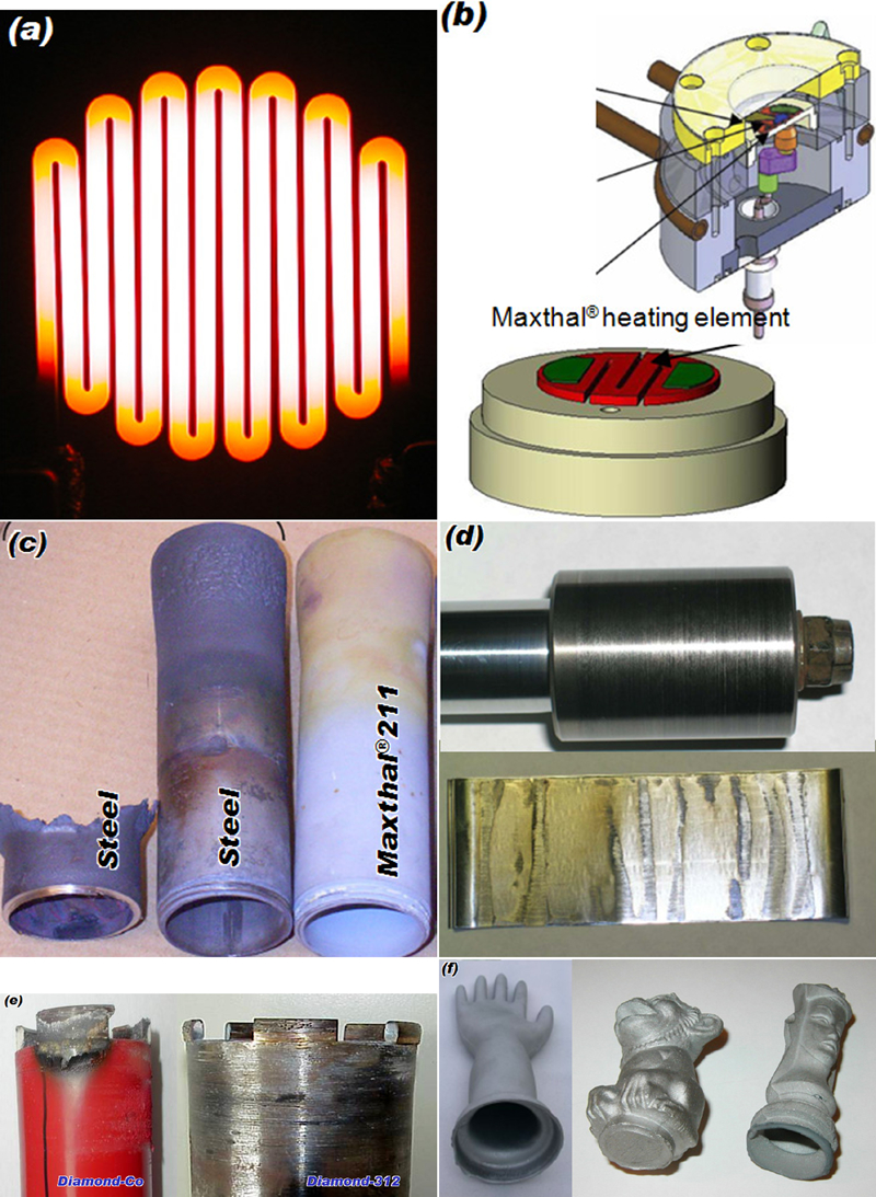
Some examples of MAX phases applications
Maxthal 211 was also shown to be superior to steel when used as gas burner nozzles, in sulphur containing natural gas corrosive burning environments. Figure 16c compares nozzles made of Maxthal 211 and 353MA steel after one year in a furnace at 1473 K. The α-Al3O2 scale that forms on the Ti2AlC protected the material and allowed an increase of the process temperature up to 1673 K. Because of the excellent machinability, threading enabled the MAX phases nozzles to directly replace the steel ones.
A project funded by the Office of Navy Research led to the successful development of MAX based materials for foil bearings, having low friction and wear from room temperature to 823 K. Figure 16d shows a Ta2AlC/Ag shaft and a superalloy foil after testing for 10 000 cycles in a rig. The shaft was rotated at 50 000 rev min−1.329 Honeywell Inc. is further developing this concept.
3-ONE-2 and Hilti developed tooling for the dry drilling of concrete, consisting of diamonds in MAX 312 segments, which were then brazed to steel. The performance of the MAX phase segments was reported to be far superior to that of current diamond/Co segments (Fig. 16e ). With further improvements in design to overcome the problem of smearing of concrete powders due to high temperatures and the inadequate toughness of the segments, this material may be close to market.
The success of slip casting of MAX phases has extended the potential application of these materials. For example, three-dimensional shaping and sintering to final size of fully dense and hollow objects has been achieved (Fig. 16f ).
Owing to their good electrical conductivity and tribological properties, in addition to the acceptable mechanical properties, MAX phases such as Ti3SiC2 and Ti3AlC2 have been shown to perform better than carbon based pantographs for electric trains. Currently, a few leading projects are running in China, aiming for application on the high speed railway under construction.
In addition to the applications mentioned above, a number of other potential applications have been mentioned in previous sections. These include: electrodes, exhaust gas filters for automobiles, free-cutting elements, microelectronics, biomaterials, damping materials (high stiffness and up to high temperatures), corrosion resistant materials, surface coatings, defence applications, such as armour, nuclear applications, low dimensional materials, and substrates for CVD diamond.
Development of key technologies of MAX phases, such as pressureless sintering, surface coating by PVD and MAX based composites, is considered most likely to lead to more breakthroughs in the application of MAX phases in the near future.
Future directions
The most urgent issue in MAX phase research is to develop viable commercial applications for these materials. With the preliminary and potential application fields discussed above, market penetration by MAX phase materials will create more stimuli to carry out more research and development on this family of layered metallic ceramics. Research on MAX phases is currently funded by agencies, science foundations and defence industries in the USA, China, Europe and Australia. However, funding for research on MAX phases from governmental agencies in Japan is almost zero. The likelihood of the Japanese government funding such research remains small until a clear market scenario is available.
Another important issue is the search for new MAX phases. First, to better understand the MAX phases themselves, both those known to exist and those theoretically predicted to be thermodynamically and mechanically stable. To do so, thorough experimental investigations into the properties are needed. The second priority is to discover more MAX phases. It is encouraging that in the past few years many MAX phases, particularly 413 and 312 phases, have been discovered. More 312 or 211 MAX phases, plus their solid solutions, which are numerous, are awaiting exploration.
Cost is also a challenge. However, with the diverse selection of the M, A and X elements, and the increasing diversity in starting reactants such as binary M–X, M–X, A–X compounds and even oxides, MAX phases with reasonable cost are not out of reach. In addition, processes such as pressureless sintering provide decreased cost, with the possibility of fabricating MAX phases in larger quantity and complex geometries. This has already been shown to be possible for some products as demonstrated by the 3-ONE-2 and Kanthal joint venture.
Footnotes
Acknowledgements
Contributions from the author’s colleagues Dr H. Hashimoto, Dr T. Abe, and postdoctoral research fellows Dr Z. F. Zhang, Dr S. L. Yang, Dr Y. Zou, Dr Y. L. Du, Dr W. B. Tian to the studies on the MAX phases are appreciated. The inspiration provided by collaboration with Dr M.W. Barsoum is also acknowledged; his advice and discussion have been invaluable. Dr M. W. Barsoum and Dr Y. C. Zhou are acknowledged for their critical reading of and comments on this manuscript. The author would also like to thank Nihon Dennetsu Co. Ltd for financial support.