
Abstract
The use of heavy gauge steel sheets for structural applications often requires a combination of high yield strength and adequate toughness. The most cost effective way to achieve high yield strength and high ductility in low alloyed steels is through grain refinement. In industrial practice, such refinement is commonly obtained by thermomechanical controlled processing (TMCP). This approach comprises slab reheating to well defined temperatures, a large amount of hot deformation below the non-recrystallisation temperature T nr and accelerated cooling. In practice, the T nr is generally raised by the addition of microalloying elements such as Nb and Ti. As these elements contribute substantially to the alloying costs, optimisation of their use allows for a decrease in production cost. Better understanding of the T nr assists in tuning the rolling process so that optimum mechanical properties can be produced. One area of importance is to recognise that the concept of the T nr was originally developed for reversing mills and the production of plate steels. Methods of defining and determining it must be modified if it is to be applied to strip mills and their associated short interpass times. The main goal of this review is to provide a concise and complete overview of the current understanding of the fundamental mechanisms that control the T nr and to address the different methods that can be used to determine it.
High strength low alloy steels for structural applications
High strength low alloy (HSLA) steels represent a group of low carbon steels that utilise small amounts of alloying elements, such as Mo, Nb, Ti and V, to attain yield strengths in excess of 275 MPa in the as rolled condition. The principal goal of these microalloying additions is ferrite strengthening by grain refinement, precipitation hardening and solid solution strengthening. The principles of strengthening and grain refinement by such additions are described below. Furthermore, the high strength of HSLA steels can be produced at relatively low carbon levels so that the weldability of many HSLA steels is at least comparable to that of mild steel. Owing to their superior mechanical properties, they allow more efficient design with improved performance even under difficult environmental conditions. Furthermore, they permit reductions in component weight and manufacturing cost.
HSLA steels are used for various structural applications. Figure 1 illustrates the improvement in HSLA steel quality within the framework of the development of new pipeline steels in recent decades.1 An extensive review of the evolution of the strength of microalloyed steels has also been published recently by DeArdo et al. 2
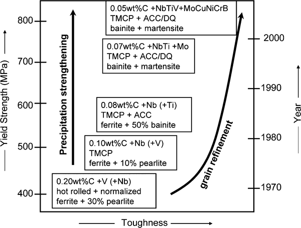
Development of pipeline steels as example of HSLA steel research (TMCP: thermomechanical controlled processing; ACC: accelerated cooling; DQ: direct quench)1
The application of large diameter pipe was a forerunner and driving force in the development of HSLA steels because pipeline operators demanded higher transportation capacity in the 1960s for economic reasons.3, 4 Higher operating pressures and lower operating temperatures required improved toughness and higher impact energies in order to avoid brittle fracture, simultaneously accompanied by strength increases. This could only be fulfilled by refining the grain size and reducing the amount of second phases, such as inclusions and pearlite. Therefore, high cleanliness, represented for example by low sulphur and carbon contents, are prerequisites in HSLA steels. Furthermore, the economics of steel production also had to be improved by replacing conventional heat treatments (normalising, quenching and tempering) by controlled rolling processes and consequently producing the required properties directly in the as rolled condition. Several specific rolling and cooling regimes have been developed to achieve this goal. These concepts are now widely used, not only for the production of large diameter pipe, but for other grades of construction materials as well, thus enabling steel to maintain its position as the most widely used structural material. Other HSLA steel applications include high rise buildings, car park decks, bridges, offshore structures, power transmission towers, lighting poles, building beams and panels, heavy duty highway and off-road vehicles, construction and farm machinery, storage tanks, etc. Some of these uses are illustrated in Figure 2.

Typical applications of HSLA steels: offshore platforms, pipelines, ship building, transmission towers, building construction and bridges
Thermomechanical controlled processing
The metallurgical principle governing the development of HSLA steels is that of grain refinement since this is the only way to improve both the strength and toughness of steel. The most cost effective way of producing grain refinement is thermomechanical controlled processing (TMCP), as illustrated schematically in Fig. 3. This process consists of three important steps:
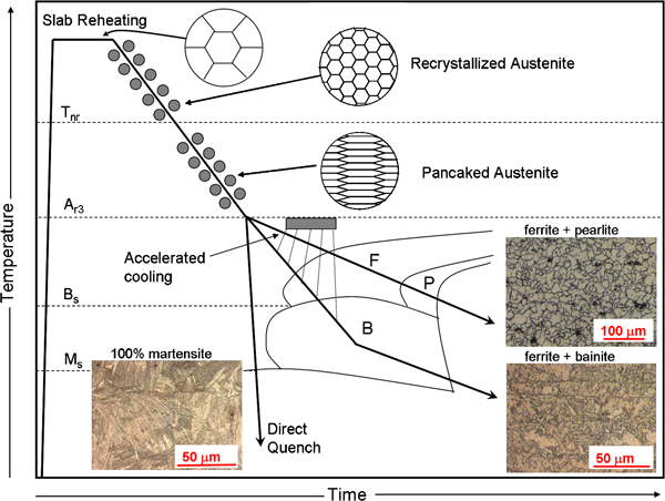
Schematic diagram of thermomechanical controlled processing (TMCP) and microstructures that result from this process
Limiting the slab reheating temperature
To make the forming process easier, relatively high soaking temperatures are traditionally employed, which cause considerable grain growth. Hence, the first step in controlled rolling is to control the grain size during reheating. It is well known that the austenite grain size is related exponentially to the soaking temperature. Therefore, the lowest soaking temperature that leads to solution of the microalloying elements should be employed. For most steel grades, this is determined by the niobium and carbon contents. Titanium forms a very stable compound TiN, which remains undissolved. This compound consequently limits austenite grain growth at relatively high soaking temperatures and also keeps the nitrogen from forming the Nb(C,N) phase, enabling the dissolution of NbC to occur more readily.
Final deformation in the low temperature austenite region
This is the temperature range within which complete static recrystallisation no longer takes place between rolling passes. Deformation in the low temperature austenite region (characterised by T<T nr = non-recrystallisation temperature, as discussed in detail in the section on ‘The concept of the “non-recrystallisation temperature”’) leads to the retention of work hardening, which is accompanied by the formation of pancaked grains and deformation bands. Consequently, increased numbers of nucleation sites are made available for the γ to α transformation. This promotes the formation of a fine grained microstructure, fulfilling the requirements for both strength and toughness.
Accelerated cooling
By employing faster cooling rates, further grain refinement can be achieved. This lowers the transformation start temperature and thus provides more nuclei in the undercooled austenite. While the air cooling of structural steels results in a ferrite–pearlite microstructure, accelerated cooling avoids the transformation to pearlite and provides a microstructure of ferrite and bainite (or bainite and martensite). Up to a yield strength level of about 500 MPa, ferrite–pearlite microstructures are produced, while higher strength steels require bainitic constituents. Steels with about 700 MPa yield strength are typically fully bainitic (or bainitic with the presence of martensite islands).
Thermomechanically rolled steels are gaining constantly in importance because of their outstanding cost to performance ratio. Today, a variety of high strength low alloy steels are processed via hot strip mills since, in comparison to plate mills, they offer a lower cost route, especially for thinner gauges. Because the interpass times pertaining to strip mills are appreciably shorter than those associated with (reversing) plate mills, different metallurgical considerations come into play. With respect to rolling schedules, the requirements for thermomechanical processing therefore have to be optimised with regard to the conditions applicable to strip mills. Better knowledge of processing–microstructure–property relationships is the key to such optimisation.
Properties of HSLA steels
The main properties of HSLA steels that make them suitable for a wide variety of applications are: strength and toughness, weldability, corrosion resistance and cost effectiveness.
Mechanical properties
HSLA steels are considered as ‘high strength’ steels, but only in a relative sense compared to mild steel, with yield strengths in the range 355–800 MPa. This limitation is the result of an approach towards system optimisation where the strength of the material has to be considered with respect to other properties such as fracture toughness, formability, weldability or corrosion resistance.
Gladman and Pickering developed formulas for the mechanical properties of 0·1–0·2 wt-% C–Mn microalloyed steels with predominantly ferritic microstructures, i.e. less than 20% pearlite. The total yield strength of HSLA steels is dependent on multiple strengthening mechanisms, as indicated in equation (1)
According to Pickering, the common substitutional alloying elements (Cu, Mn, Ni, P and Si) have the following strengthening effects, where the alloy concentrations are in weight per cent7

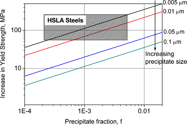
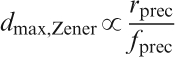
As the concentration of a solute is increased beyond its solubility limit in Fe, precipitates may form inside the grains, which may also increase the strength. The precipitates also produce strengthening by impeding the motion of dislocations through the lattice. When a dislocation moving along its glide plane encounters a precipitate, it may either loop around such a particle, if it is impenetrable (the Orowan mechanism8,
9), or cut through it,10 shearing the precipitate in the process. The increases in strength due to particle looping and particle cutting, are given, respectively, by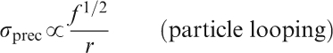

Precipitation strengthening of ferrite based on Ashby–Orowan model
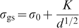
Finally, the ferrite grain size also has an important effect on the strength. This contribution is described by the Hall–Petch equation11,
12
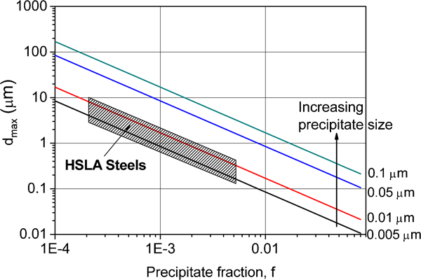
Effect of precipitate volume fraction and size on maximum grain size
The strength benefits of HSLA steels can only be realised if the product remains safe as well. This means that the steel must be tough at operating temperatures. In general, HSLA steels have low DBTTs due to their fine grain sizes. Gladman et al.
13 developed the following formula for the DBTT of HSLA steels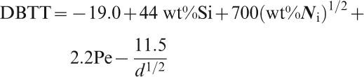
From equations (5) and (7), a number of important conclusions can be drawn:
ferrite grain refinement is beneficial for both strength and toughness
the presence of pearlite is detrimental to the toughness
the effect of precipitation is not taken into account in equation (7).
The effect of Nb(C,N) precipitation on the toughness has been analyzed by several researchers in the past and various values have been proposed for this effect. The increment in impact transition temperature pertaining to the increase in yield strength associated with precipitation strengthening was determined to be 0·35°C MPa−1 by Gladman et al.,14 0·55°C MPa−1 by Gray15 and 0·32°C MPa−1 by Vervynckt et al. 16 By contrast, Tamehiro et al. 17 have reported that there is no effect of Nb(C,N) precipitation on the impact transition temperature of a 0·03C-0·046Nb steel. Furthermore, Lin et al. 18 have also shown that precipitation strengthening does not affect the toughness of a 0·03C–0·09Nb steel.
Transition temperatures (the temperature at which the impact energy is 40 J) and yield stresses are compared for various HSLA steels with different microalloying additions in Fig. 6. The highest yield strengths and lowest transition temperatures are obtained when Nb and Ti are employed together.
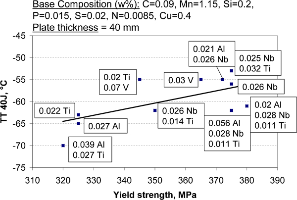
Overview of literature data on mechanical properties of thermomechanically hot rolled HSLA steels19
Weldability
Since welding is now the most widely used fabrication method and with the tendency towards the use of higher heat input welding processes, weldability has become an important issue in the development of HSLA steels. It is essential that chemical compositions can be employed that promote fusion of the base metal and filler (i.e. weld electrode) metal, without the formation of cracks and other imperfections. HSLA steels have excellent weldabilities due to their low carbon equivalents. The International Institute of Welding defines the carbon equivalent P
CM, an empirical measure of the weldability for steels with carbon contents in excess of 0·18 wt-%, as follows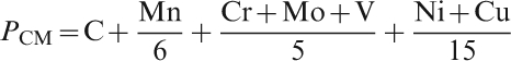

Corrosion resistance
Small additions of Cu, P, Si or Cr to low alloy structural steels can improve the corrosion resistance by the formation of a protective rust layer. This allows structures to be built without requiring painting or the use of other corrosion prevention techniques. Such steels develop a natural adherent patina in the surface layer that resists further corrosive attack. The weathering steels, structural HSLA steels with improved atmospheric corrosion properties, are commonly known as Cor-Ten steels, their original US brand name.
Cost effectiveness
The necessary dimensions of a structure are determined by calculating the stresses imposed by the service load and employing a yield strength based on the guaranteed minimum yield strength of the steel. By using a steel with a higher yield strength, the thickness and thus the weight and consequently the cost of a construction can be considerably reduced. Furthermore, by the introduction of TMCP as the main process for the production of HSLA steels, expensive heat treatments can be avoided.
Chemical compositions of HSLA steels
HSLA steels are designed to provide better mechanical properties and/or greater resistance to atmospheric corrosion than conventional carbon steels. They are not considered to be alloy steels in the normal sense because they are designed to meet specific mechanical properties rather than a specific chemical composition. This implies that the chemical composition of a particular HSLA steel may vary for different product thicknesses so that the mechanical property requirements can be satisfied. HSLA steels in sheet or plate form have low carbon contents (<0·25 wt-%C) in order to have adequate formability and weldability; they may have manganese contents up to 2·0 wt-%. Small (‘microalloying’) quantities of molybdenum, niobium, titanium and vanadium are used in various combinations.
As outlined above, the principal function of alloying elements in HSLA steels is ferrite strengthening by grain refinement, precipitation strengthening and solid solution strengthening. Solid solution strengthening is closely related to the alloy content, while grain refinement and precipitation strengthening depend on the complex interaction of alloy composition and thermomechanical treatment. Alloying elements are also selected to influence the transformation temperature in order to lower the temperature at which austenite transforms to ferrite and pearlite during air cooling. A finer grained transformation product is produced in this way, which is a major source of strengthening.21 An overview of the most common alloying elements employed in HSLA steels is presented in Table 1, together with the most important effects of these elements.
Alloying elements frequently used in HSLA steels
Carbon is the primary strength controlling alloying element for all steels. Depending on the type and strength of the steel grade, the maximum allowable amount of carbon in rolled shapes is typically between 0·12 and 0·25 wt-%. The actual amount of carbon also depends on the product size and thickness. However, for modern structural steels and bainitic pipeline steels, the carbon content is reduced to about 0·03–0·06 wt-%, and other alloying elements compensate for the strength loss associated with the lower carbon content. This reduction in carbon content was required to improve the toughness and weldability, as measured by the CE, since the CE is closely related to the actual carbon content, as discussed above.23
Titanium, niobium and vanadium are very effective as microalloying elements in steel, influencing the microstructure by both a solute drag effect and the formation of nitrides and carbides. Since the solubility product and the physical properties of each element and each compound are different, each of these elements has specific merits:
titanium forms coarse nitrides that are stable at high temperatures. These nitrides provide control of the austenite grain size at the reheating temperature before hot working and also in welds, in particular in the heat affected zone close to the fusion boundary line. Ti also forms low temperature carbides and carbosulfides, which are important strengthening precipitates. However, there is some disagreement in the literature24 – 26 as to the amount of titanium that should be added to produce the most beneficial results
niobium forms Nb(C,N), which dissolves entirely in austenite at high temperatures, leading to the following effects: (1) it retards the static recrystallisation of hot rolled austenite, resulting in grain refinement; (2) it produces increments of strengthening due to Nb in solid solution as well as by the precipitation of Nb(C,N).27 Strain induced precipitates of Nb(C,N) in austenite, with typical particle sizes of about 20 nm, are too large to contribute significantly to the strength increases by precipitation hardening. By contrast, the precipitates formed in the ferrite are much smaller with diameters of about 1·5 nm. When 0·02 wt-% niobium remains in solid solution at the finish rolling temperature, strength increases of around 90 MPa can result from such ferrite precipitation; and (3) Nb has a pronounced effect on the γ to α transformation, which it retards considerably even at very low solute Nb concentrations. This is somewhat unexpected, as Nb is a ferrite stabiliser. Nevertheless, Nb retards the growth of ferrite by exerting solute drag on the moving phase boundary. A complicating effect is the possible formation of NbC and Nb(C,N), which also influences the γ to α transformation. The role of Nb in modern steels has been reviewed in detail by DeArdo28
vanadium forms almost no precipitates in austenite and is therefore available for precipitation hardening during or after the γ to α transformation. The precipitation of V(C,N) in ferrite can lead to significant strength increases depending not only on the rolling schedule used, but also on the chemical composition. A detailed review of the processing, microstructure and properties of vanadium microalloyed steels has recently been presented by Baker29
Molybdenum, copper and nickel are often added to newly developed heavy plate products:
molybdenum is added to hot rolled HSLA steels primarily to improve the hardenability, i.e. when transformation products other than ferrite–pearlite are desired. Although Mo retards the growth of bainite by a solute drag mechanism, it retards ferrite and pearlite formation to a much greater extent. Molybdenum also increases the solubility of niobium in austenite, thereby promoting the precipitation of Nb(C,N) in the ferrite. This increases the precipitation strengthening effect of Nb(C,N)30
copper is added for improved corrosion resistance (e.g. in weathering steels). Cu increases the strength of both low and medium carbon steels by ferrite strengthening,31 which is accompanied by only a slight ductility decrease. Cu can be retained in solid solution even at the slow cooling rates experienced when heavy sections are normalised; nevertheless, precipitation can be induced when the steel is reheated to about 510–605°C
nickel is often added to copper bearing steels to minimise the hot shortness. Nickel, usually between 0·25 and 0·5 wt-%, also improves the fracture toughness and corrosion resistance. The toughness increase is due to the fact that Ni increases the number of grain boundaries, i.e. it causes grain refinement by reducing the austenite to ferrite transformation temperature.32
Concept of ‘non-recrystallisation temperature’
The use of heavy gauge steel sheets for structural applications often requires a combination of high yield strength and acceptable toughness. The most cost effective way to produce this combination in a low alloy steel is, as indicated above, grain refinement. In industrial practice, such refinement is commonly accomplished by TMCP. The microstructural changes taking place during deformation and subsequent recrystallisation are illustrated in Fig. 7 taken from simulations33 on a deformation dilatometer. The microstructure of an ultralow C–Mn–Nb steel (11 ppm C, 1·47 wt-%Mn, 0·26 wt-%Si, 0·022 wt-%Al, 0·16 wt-%Nb, 40 ppm Ti and 12 ppm N) after reheating to 1250°C for 300 s but before deformation is presented in Fig. 7a . Since the precipitates were dissolved during reheating, grain growth was not inhibited and the grains attained a mean size of 261 μm.
Austenite recrystallisation behaviour of microalloyed ultra low C–Mn–Nb steel before deformation and during isothermal holding after compression (ϵ = 0·2, dϵ/dt = 0·5 s−1) at 1075°C (etched with the Béchet–Beaujard reagent)33
The microstructure 1 s after the first deformation (at 1075°C) is illustrated in Fig. 7b . Recrystallisation can be seen to have begun at the austenite grain boundaries, which are highly serrated. The recrystallised grains nucleate predominantly at the austenite grain boundaries, where new fine grains are visible (Fig. 7c ). These microstructural changes produced a fractional softening of about 30%, determined in a double deformation test. Finally, after 100 s, the material was fully softened and fully recrystallised (cf. Fig. 7d ). The deformed+recrystallised grains now have a mean size of 125 μm, thus demonstrating the grain refinement effect of a deformation and recrystallisation cycle.
To take advantage of rolling below the T nr, reductions of 50–80% have to be applied below this temperature. After reheating at about 1200°C, hot rolling is typically performed in two sequences, roughing and finishing. The first sequence is carried out at temperatures well above 1000°C, leading to repeated steps of grain refinement, such as that typified in Fig. 7. The second sequence is ideally performed below the non-recrystallisation temperature. If this temperature is relatively low, the conditioned plate has to be cooled until the required temperature is reached. The waiting time between roughing and finishing, however, results in a loss of production. Suitable understanding of the T nr and its role can help to optimise the rolling process and to produce the required mechanical properties most effectively. In addition, accurate knowledge of the recrystallisation kinetics is also required. The precise determination of these behaviours is of importance because it enables the dependence of the rolling load on temperature to be predicted with accuracy. It also permits optimisation of the relative amounts of austenite pancaking and ferrite work hardening.
Although the T nr temperature is a well defined concept and can be readily determined under specific conditions, the physical characteristics of this phenomenon are still inadequately understood. It should be mentioned that alternative procedures exist for the production of fine-grained microstructures, for example, by dynamic strain induced transformation. This topic has recently been reviewed by Beladi et al. 34 and will not be considered further here.
Definition of the T nr
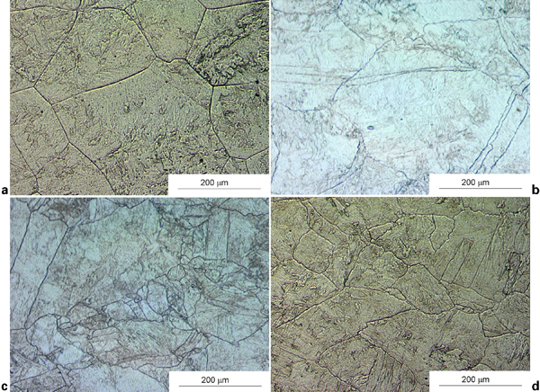
From a theoretical point of view, the non-recrystallisation temperature T nr is defined as the temperature below which static recrystallisation can no longer go to completion in the interpass interval or during cooling. Deformation below the T nr leads to the accumulation of strain hardening and results in the appearance of elongated grains (pancake structure) and the formation of deformation bands. In clean steels, the most relevant nucleation sites for the austenite to ferrite transformation are the austenite grain boundaries. In the case of the transformation of deformed austenite, dislocation bands within the grains will also act as nucleation sites. After nucleation, the ferrite grains grow until impingement of the grains occurs. The ferrite grains will be finer when the transformation starts from finer austenite grain sizes and especially from an elongated austenite grain microstructure, where the ratio of grain boundary surface area to grain volume is increased. This higher nucleus density in combination with the high nucleation rate caused by accelerated cooling, will finally lead to a significant finer ferrite grain size.35, 36 The concept of the T nr is illustrated schematically in Figs. 8 and 9.
Illustration of deformation above T nr with complete static recrystallisation of austenite between rolling passes i and i+1
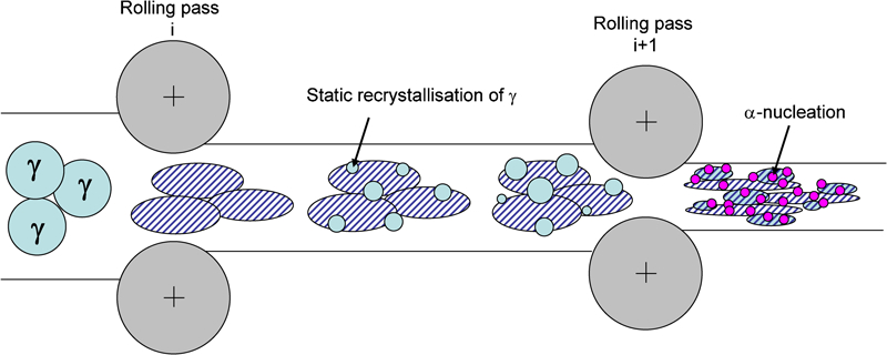
Illustration of deformation below T nr, with only partial recrystallisation of austenite between rolling passes i and i+1: heavily deformed (‘pancaked’) austenite grains result in more nucleation sites for austenite to ferrite transformation
Determination of T nr
The non-recrystallisation temperature T nr represents the start of the inhibition of complete static recrystallisation during cooling between rolling passes. Unlike a melting point or phase transition temperature, the T nr is not an exact quantity. Generally speaking, interpass recrystallisation begins to be incomplete some 50°C or so above the temperature at which it is arrested completely under the interpass time conditions of interest. This gradual transition in recrystallisation behaviour will be examined more closely below. The most common method for determining the T nr consists of simulating successive rolling passes and representing the mean flow stress (MFS) versus the inverse of absolute temperature graphically for each of the simulated passes. The inhibition of recrystallisation indicated by the T nr appears as a change in slope of the MFS curve, as demonstrated in more detail below.
The non-recrystallisation temperature is usually determined by multideformation testing. After a reheating step, a sample is subjected to a series of consecutive deformations separated by specific time intervals, while the specimen is cooled at a selected cooling rate. The stress σ and strain ϵ are registered during each of the deformation passes. An example of the stress–strain curves determined in such a multideformation test is presented in Fig. 10a .33
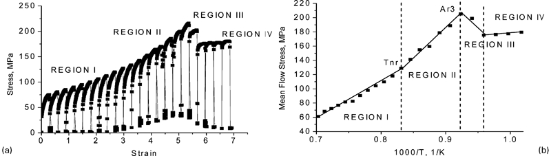
a stress–strain curves obtained from multideformation test on low alloy steel (0·02 wt-%C, 1·50 wt-%Mn, 0·26 wt-%Si, 0·043 wt-%Al, 20 ppm Ti and 18 ppm N) and b mean flow stress versus inverse of absolute temperature33
The simulation of a 23 plate rolling pass schedule for a low alloy steel is illustrated in Fig. 10, where fixed interpass times of 20 s have been employed in conjunction with a cooling rate of 1°C s−1. The flow stress increases as the temperature is decreased (Fig. 10a ), and the curves can be seen to change their shapes on entering into region II. Later (and thus at lower temperatures), the flow stress drops, region III, before increasing again, region IV. These zones can be better interpreted with the aid of Fig. 10b , in which the MFS is plotted against the inverse absolute temperature. The MFS is calculated for each deformation step by dividing the area under the stress–strain curve by the applied strain. It should be noted that the simulations employed are always based on constant pass strains, strain rates, cooling rates and interpass times. By contrast, all these quantities vary continuously in industrial mills. However, it is the trends in the MFS versus 1/T relationship that are employed to define the transitions between the zones. These could suggest false transitions if the pass strain, strain rate or temperature interval was changed from pass to pass instead of being held constant.
Four different zones can be distinguished in Fig. 10b :
in the first zone (region I), which corresponds to deformation at high temperatures, the MFS increases slightly as the temperature is decreased. The austenite recrystallises completely between passes and there is no accumulation of work hardening (i.e. of dislocations). The flow stress increase is solely due to the decrease in temperature
in the second zone (region II), there is a change in slope, which indicates that dislocations are being accumulated and that hardening is being retained. Here the flow stress increases more quickly with decreasing temperature because of the inhibition of recrystallisation between passes
the third zone (region III) is characterised by a significant drop in MFS and corresponds to the start of the austenite to ferrite transformation. This is the part of the temperature range where intercritical (two-phase) rolling takes place
the fourth zone (region IV) corresponds to the warm rolling of ferrite, where the temperatures are all below the Ar 1.
The intersection of the straight regression lines fitted to regions I and II defines the T nr and the intersection of the regression lines fitted to regions II and III determines the value of Ar 3, i.e. the ‘upper critical’ or austenite to ferrite transformation start temperature. This temperature is only applicable to deformed, i.e. unrecrystallised austenite and depends on the chemistry, cooling rate, interpass time and applied strain (reduction).37 Similar remarks apply to the Ar 1, which is defined by the break between regions III and IV. It should be noted that the ‘true’ MFS versus 1/T relationship in Fig. 10b is actually curved in the vicinity of the vertical T nr line; that is, the actual behaviour is not correctly described by the two straight lines that intersect at this point. Instead, the transition in the recrystallisation behaviour is more gradual than shown.
Because the T nr depends on interpass time, it is important to note that a simulation involving 10 or 20 s interpass intervals does not apply to schedules in which the interpass time is in the range of 1 s. The point of importance is that plate or reversing mills involve interpass times that permit carbonitride precipitation to take place, as discussed in more detail below. Such precipitation arrests both dynamic and static recrystallisation. By contrast, the much shorter interpass times applicable to strip mills mean that carbonitride precipitation is unable to play a significant role and the inhibition of recrystallisation largely takes place by means of solute drag instead.38 This phenomenon is also examined in some detail below. For this reason, simulations employed to determine the T nr should be carried out using the length of interpass interval appropriate to the process of interest.
Strip mill simulations are more difficult to perform than plate mill simulations, because much less cooling (temperature decrease) can be accomplished during the rather short interpass intervals. Accordingly, several sets of tests must be carried out to cover a given rolling temperature range and average interpass condition. As a result, this type of test is still under development and presents a challenge to the experimentalist.
Recrystallisation kinetics
Ideally, process improvements and rolling schedules for new products should be tested under actual industrial conditions. Such experiments, however, are often impossible to carry out or at least expensive to perform. Consequently, preliminary tests on a laboratory scale can provide useful information regarding the hot rolling behaviour of selected materials before industrial trials are carried out. Of importance is knowledge regarding the high temperature recrystallisation behaviour of the material of interest. Two types of experimental approaches have been proposed in the literature for the quantification of the recrystallisation kinetics: (1) direct observation methods such as optical microscopy39 and electron backscatter diffraction;40 and (2) indirect mechanical methods, such as multideformation tests,37, 41 double deformation tests42 – 49 and stress relaxation tests,50 – 53 which are based on measuring the progress of softening.
The direct measurement of the recrystallised fraction in microalloyed steels is difficult because the material transforms during cooling and special etching techniques must be used to reveal the former austenite grain boundaries. One of these is the Béchet–Beaujard54 method, the use of which was illustrated in Fig. 7. This procedure is tedious and time consuming; furthermore, in many cases, it cannot be used because of low hardenability as well as the practical difficulties associated with observing quenched austenite. Moreover, it is often difficult to distinguish between the recrystallised and deformed prior austenite grains, so that the analysis often involves a measure of subjectivity.
For this reason, mechanical testing techniques are generally preferred, which can be divided into two main groups. The first consists of multideformation tests carried out under continuous cooling conditions. These have been described above and are mainly focused on determination of the non-recrystallisation temperature.55 Such multideformation tests are mainly performed in torsion due to the possibility of applying large total strains. For example, Maccagno et al. 55 showed that there is excellent agreement between torsion testing simulations of this type and rolling mill data. This technique, however, does not provide any basic information regarding the static recrystallisation behaviour of microalloyed steels in the interval between two rolling passes. Although laboratory rolling and deformation dilatometry can also be used to provide multiple deformations, the use of these methods has not been reported in the literature.
The second group of experiments employs the isothermal deformation technique. The best known ones in this group are the double hit test56 (DHT) and the stress relaxation test57 (SRT). These techniques permit determination of the progress of softening as a function of temperature in the time interval after or in between deformation passes. Isothermal deformation tests can be performed with a variety of deformation modes on different types of equipment, such as torsion on a hot torsion machine,58, 59 uniaxial compression on a deformation dilatometer45, 46 or a high speed press,43, 60 and plane strain compression on a cam plastometer,61 a mechanical testing system/Instron machine62 or Gleeble.63, 64
Although there is a considerable amount of literature data available regarding the recrystallisation kinetics of microalloyed steels, it is difficult to compare these data since the deformation schedule, equipment used and analysis method all influence the resulting derived kinetics. So far, only a few comparisons have been made between the different techniques and methods. Jonas et al. 55 compared the T nr values obtained from hot torsion simulations with those obtained from industrial mills and Gomez et al. 39 and Liu and Akben65 compared the results of isothermal double deformation tests to continuous cooling multipass hot rolling simulations. Iparraguirre et al. 66 studied the differences in recrystallisation behaviour deduced from different double deformation mechanical testing modes, i.e. uniaxial compression on a dilatometer and torsion tests. They observed some important differences between the recrystallised fractions determined by these methods. Fernandez et al.,58 Andrade et al. 60 and Yanagida and Yanagimoto67 described the differences in recrystallisation behaviour deduced using different methods to analyse a double deformation test. Other studies63, 64, 68, 69 have compared the recrystallised fractions obtained after a double deformation test and after a stress relaxation test. Significant discrepancies can be found, since some authors63, 64 find good agreement between the fractions obtained from a DHT and a SRT, while others69 have reported that recrystallisation is accelerated in a SRT. However, since these authors used different equipment and analysis methods to obtain their results, it is difficult to determine the reasons for the observed discrepancies. An additional problem stems from the non-uniform ways employed to evaluate the softening ratio, i.e. to separate the softening fraction due to recovery from the softening fraction due to recrystallisation.
The above survey indicates that, although comparisons between the different methods have been reported in the literature, some discrepancies remain to be accounted for. Recently, some work was reported in which a systematic comparison was presented for a single alloy in order to determine the relationships between the recrystallisation kinetics in the static recrystallisation region,70 different test procedures (double deformation and stress relaxation), different types of equipment (hot torsion, deformation dilatometry and mechanical testing system compression testing) and different analysis techniques. This comparison was then extended to different test procedures (multideformation and double deformation) combining different types of equipment (laboratory rolling, hot torsion and deformation dilatometry) and different analysis techniques.71
The former publication70 led to the conclusion that it is preferable to determine the fractional softening in double deformation tests using either the 5% true strain or the 2% offset method to define the yield stress. This is because they tend to limit the effect of recovery on the fractional softening, as was also demonstrated by Li et al. 43 and which can be assumed to be a reasonable assumption for austenite as the amount of recovery is relatively low. The latter definition was proposed as the more accurate and reliable one. Details and practical aspects of the different methods have also been discussed by Fernandez et al. 58
Although the method used for analysing data influences the derived kinetics of recrystallisation, double deformation tests have been identified as the most useful when comparisons are to be made between the results of different authors. The type of testing equipment does not seem to have an important influence on the calculated softening fractions. On the other hand, stress relaxation tests appear to display several drawbacks when evaluating the recrystallisation behaviour of microalloyed steels. First of all, the precise set-up of the equipment and control of the temperature are both difficult, so that apparent differences in recrystallisation kinetics are determined when the same test is performed with different types of equipment. Furthermore, there is no standard method for analysing relaxation curves applicable to all equipment types and testing temperatures. Finally, comparison of the recrystallisation rates determined in this way with those from double deformation tests is not straightforward.
The conclusion was drawn in the latter publication71 that laboratory rolling, torsion testing and deformation dilatometry can all be used to evaluate the influence of chemical composition and of various process parameters on the T nr. The results showed that, for all equipment types, the T nr was increased by approximately 65°C when 0·16 wt-%Nb was added to a C–Mn reference steel. However, the application of T nr values derived in laboratory tests to industrial conditions needs to be done with care. Moreover, it also appeared to be possible to link the recrystallisation behaviour deduced from isothermal double deformation tests to the T nr values determined from multideformation tests under continuous cooling conditions.
Physical metallurgical principles behind T nr: interaction between deformation, recovery, recrystallisation, solute drag and precipitation
The T
nr temperature is a complex concept since it is influenced by the interaction between four different mechanisms: recovery, recrystallisation, solute drag and precipitation. These mechanisms influence each other and all depend on the parameters of the preceding deformation, characterised by the deformation temperature T
def, the strain ϵ and the strain rate 

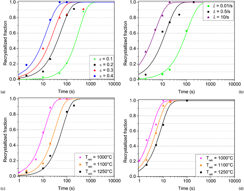
Influence of a strain ϵ, b strain rate ·ϵ, deformation temperature T def (by comparing c and d), and soaking temperature T reh (both visible in c and d) on recrystallisation behaviour of C–Mn steel:33 standard test parameters were T reh = 1250°C for 300 s, ϵ = 0·2, ·ϵ = 0·5 s−1
A schematic overview of the different interacting parameters is presented in Fig. 13 and the influence of these basic parameters is discussed in detail in this section. The roles of the main alloying elements in determining the T nr will be outlined mainly in the section on ‘Recrystallisation behaviour of HSLA steels’.
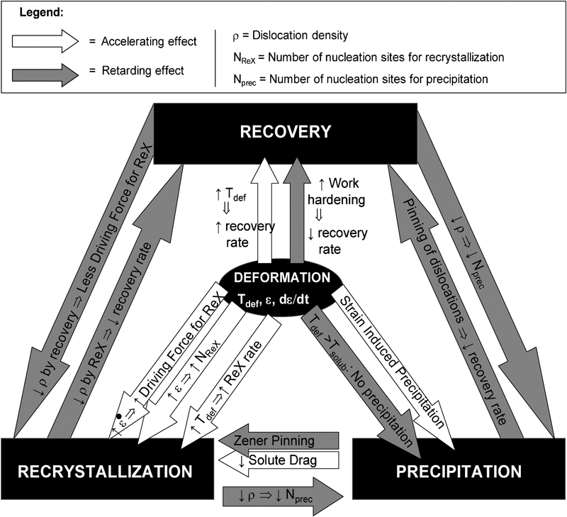
Schematic illustration of interactions between deformation, recovery, recrystallisation and precipitation
I nteraction between recrystallisation and precipitation
In microalloyed steels, recrystallisation and precipitation can interact in at least three distinct ways: (1) a decrease in dislocation density through recrystallisation reduces the number of precipitate nucleation sites available and can thus retard the onset and rate of precipitation; (2) a precipitate dispersion can provide a pinning (Zener) force72 that can retard or halt the progress of recrystallisation; (3) the mobility of grain boundaries is strongly affected by the solute content of the matrix (solute drag). The progress of precipitation, which reduces the matrix solute content, also affects the mobility of grain boundaries. Fine precipitates can pin boundaries and coarse precipitates can enhance the progress of recrystallisation by removing Nb from solution.
When precipitation starts before recrystallisation is finished, this results in a shift of the curve that indicates the end of recrystallisation R F to longer times, as shown in Fig. 14a . Thus, the recrystallisation is retarded. If precipitation starts before the onset of recrystallisation (at high deformations due to strain-induced precipitation or at low temperatures), then both the recrystallisation start R S and finish R F curves are shifted to longer times. Frequently, recrystallisation is halted completely. Alternatively, as was already mentioned above, solute drag also delays the R S and R F curves as illustrated in Fig. 14b . The solute drag effect of Nb can even shift the R S line past the R F line for plain carbon steels.
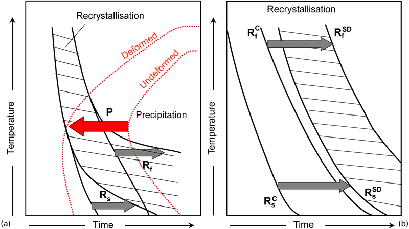
Interaction between a recrystallisation and precipitation (P = precipitation, R s = recrystallisation start, R f = recrystallisation finish) and b between recrystallisation and solute drag (C = plain carbon steel, SD = solute drag)
Interaction between recrystallisation and recovery
The driving force for both recovery and recrystallisation is the internally stored deformation energy associated with dislocations. The progress of recovery therefore reduces the driving force available for producing the migration of grain boundaries during recrystallisation and consequently will, to some extent, slow down the recrystallisation process. However, recovery processes might also increase the rate of recrystallisation by assisting in the nucleation stage of recrystallisation, for example, by giving rise to abnormal subgrain growth, as demonstrated by Huang and Humphreys.73 A detailed review of both recrystallisation and recovery and their interaction has been published by Humphreys and Hatherly.74
Yoshie et al. 75, 76 have shown that recovery is mainly controlled by the climb of dislocations after large strains at relatively high holding temperatures and when the Nb content is low. Conversely, it is mainly controlled by the annihilation of dislocations of opposite Burgers vector in the case of lower amounts of deformation and higher Nb contents. Furthermore, recovery is retarded by an increase in austenite grain size, a decrease in deformation temperature and an increase in Nb content.
Interaction between recovery and precipitation
The potential interactions between recovery and precipitation are similar to those between recrystallisation and precipitation: the presence of precipitates reduces the mobility of lattice defects such as dislocations and the presence of defects such as vacancies can enhance precipitation by increasing the diffusion rate. Similarly, at least three distinct interactions can be identified: (1) recovery may delay the progress of precipitation by lowering the number of available nucleation sites; (2) the precipitation of fine particles can pin segments of the dislocation network and therefore retard recovery; (3) microalloying elements in solution can retard the progress of recovery through solute drag effects on dislocation mobility. Furthermore, the activation enthalpy and activation volume for recovery are both influenced by the presence of microalloying elements in solution.
Effect of the preceding deformation
When the deformation temperature is raised, it is evident that the recrystallisation rate as well as the recovery rate will increase as well. When the deformation temperature exceeds the solution temperature of a precipitate, precipitation cannot take place at all. Below the solution temperature, an increase in strain during deformation increases the dislocation density, leading to faster precipitation due to a strain induced precipitation (SIP) effect. This occurs because dislocations provide nucleation sites for precipitation as well as channels for rapid pipe diffusion. Once formed, the precipitates exert a pinning force on the grain boundaries and thus retard recrystallisation77, 78 (Fig. 14).
A relationship of the type t 0·05P ( = time for 5% precipitation)∼ϵ −1 has been reported for Nb microalloyed steels.79 However, not all precipitates display SIP effects of industrial importance. Only those that precipitate in the temperature region (and during the interpass times) where hot rolling takes place can contribute to this effect. In the case of alloying with Ti, Nb and V, this means that, although TiC, NbC and the mixed carbonitrides of Ti, Nb, V are potentially able to provide SIPs, only Nb(C,N) can play this kind of role. The solubility of TiN in austenite at practical deformation temperatures is too low and therefore, these precipitates do not dissolve during reheating. On the other hand, VC has a high solubility and only precipitates after the austenite to ferrite transformation.
Higher strains and thus higher dislocation densities also provide more nuclei for recrystallisation and accelerate recrystallisation in this way. This corresponds to decreasing the T
nr. Abad et al.80 have described the dependence of the T
nr on the pass strain ϵ by the following relationship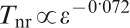
At higher strain rates, there is also less restoration by dynamic recovery. As a consequence, the less restored and more highly work hardened austenite supplies a higher driving force for static recrystallisation. This is why the T nr is lower following deformation at higher strain rates. The latter has been confirmed by Dutta and Sellars82 and later by Medina and Quispe83 and Abad et al. 84
Recrystallisation behaviour of HSLA steels
Understanding the high temperature deformation behaviour of HSLA steels is necessary to control the process and dimensional accuracy of hot rolled products as well as the final properties of these materials. Although the phenomena of recrystallisation and precipitation (and thus the T nr temperature) are strongly influenced by the chemical composition, knowledge about the effects of steel composition is still incomplete. From a technological and economic point of view, it is preferable for a material to have the highest possible T nr. In this way, less cooling time is required between rough rolling and finish rolling and a larger temperature interval is available for imposing the pancaking strain. Furthermore, the final rolling temperature can be higher, which permits the use of lower forces in the mill.
The 1988 formula of Boratto et al.85 provides an estimate of the T
nr temperature as a function of alloy composition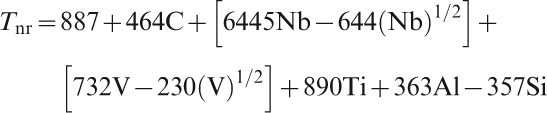
Influence of C
Although carbon has received wide attention, there is still disagreement with respect to the effect of carbon on the hot deformation behaviour of austenite as well as on the recrystallisation kinetics. To date, research has mainly focused on the effect of carbon on the hot deformation of plain carbon steels and only limited results have been reported for microalloyed steels. In the latter, carbon interacts with the microalloying elements (e.g. Nb), affecting the recrystallisation behaviour. Speer and Hansen86 showed that the carbon content clearly has a substantial influence on the recrystallisation kinetics of austenite containing 0·05 wt-%Nb. As the carbon level was increased from 0·008 to 0·10 wt-%, recrystallisation was retarded by almost two orders of magnitude. Recently, Beladi and Hodgson87 reported that the T nr temperature of a 0·03wt-%Nb microalloyed steel was increased by 40–60°C when the carbon content was raised from 0·04 to 0·11 and 0·16 wt-%, respectively. Furthermore, they found that at temperatures above the T nr, recrystallisation was only slightly influenced by the C concentration. By contrast, recrystallisation was significantly retarded by carbon at deformation temperatures below the T nr due to the formation of Nb(C,N). If the precipitates were formed during deformation, the recrystallisation rate was markedly reduced, even at very high strains.
Influence of ‘standard’ microalloying elements: Nb, Ti and V
The addition of microalloying elements such as Nb, Ti and V can increase the T nr, with Nb being the most effective element. Figure 15 indicates that a steel with just 0·02wt-%Nb will not recrystallise completely below 950°C.
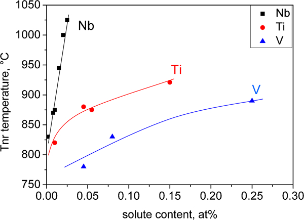
Retardation of recrystallisation due to presence of Nb, Ti and V for 0·07C–1·4Mn–0·25Si steel88
The increase in the T nr by microalloying additions can be explained in terms of two complementary mechanisms:
the solute drag effect89 by which elements in solution are enriched in the vicinity of grain boundaries and dislocations. Grain boundaries often contain higher concentrations of the alloying elements, thereby reducing both their interfacial energy and mobility. The presence of boundary solutes results in a non-linear boundary velocity characterised by a large resistance to grain boundary migration. This leads to a decrease in the recrystallisation rate. Similar remarks apply to the motion of dislocations, the retardation of which delays nucleation. An indication of the possibility of having a specific element in solid solution in the steel matrix is its difference in atomic size compared to the iron atom. The more the atomic radius differs from that of Fe, the greater the potential for this atom to produce solute drag. However, the solute drag effect is limited by the solubility limit of the element. As can be seen in Table 2, Nb and Ti as well as P, Mo and Mn can be very effective as solute drag elements
Properties determining solute drag potential89
the precipitation effect by which the precipitates exert a pinning force on the moving boundaries during recrystallisation. As the concentration of alloying elements increases they can start to form precipitates, according to the following chemical reaction
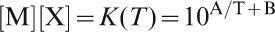
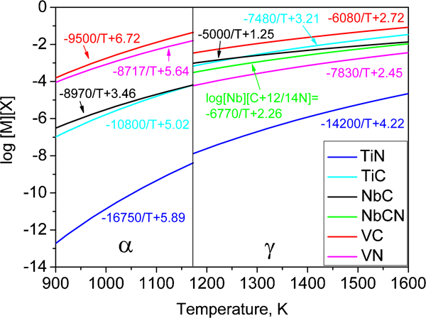
Figure 16 clearly shows that the solubility product of TiN in austenite is very low. As a consequence, in HSLA steels, all the Ti will be bound to N in the austenite hot rolling temperature range. This means that, although the solute drag potential of Ti is very high (Table 2), the actual effect of Ti as a solute drag element in retarding recrystallisation in HSLA steels will be negligible due to the very low (or even nonexistent) solute Ti content. On the other hand, the solubility of VC in austenite is rather high. As a consequence, the role of VC precipitates in retarding the austenite recrystallisation and in increasing the Tnr will be of minor importance as can already be concluded from Fig. 15.
Maruyama et al. 98 have proposed a further reason why Nb is the most effective element for delaying austenite recrystallisation. Nb atoms will trap or combine with the interstitials and/or defects more quickly than the other elements. Along with the strong interstitial–Nb interaction and dislocation–Nb interaction, the greater diffusivity of Nb is an important factor contributing to its significant retarding effect on recovery and recrystallisation. It can be seen in Fig. 17 that the diffusion coefficients of the interstitials (C,N) are more than 1000 times higher than the diffusion coefficients of the substitutional elements Ti, Nb and V. Therefore, the diffusion distance (Dt)1/2 (in which D is the diffusion coefficient and t is the time) is completely determined by the diffusivity of Nb, Ti and V and not by the diffusivity of C and N.
Diffusion coefficients of main precipitate species in HSLA steels
The exact mechanism of recrystallisation inhibition (solute drag or precipitation) is of considerable importance in the design of microalloyed steels because the microalloying elements contribute substantially to the alloying cost. As a result, optimisation of the use of these elements in combination with the production schedule permits the total production cost to be decreased. Nevertheless, it is not possible at present to distinguish clearly between the influence of these two mechanisms on the recrystallisation behaviour. If the recrystallisation kinetics is controlled by solute drag, it should only be necessary to consider the concentration of the microalloying elements dissolved in the austenite matrix. On the other hand, if carbonitride precipitation controls the recrystallisation kinetics, the levels of carbon and nitrogen in solution should also be important. Because of the important influence of interpass time on this issue (short in strip mills and long in plate mills, as discussed above), generally speaking, solute effects are more important in strip mills and precipitation effects in plate mills.
Speer and Hansen86 investigated austenite recrystallisation in Nb microalloyed steels and showed that the solute drag effects are relatively small compared to those of carbonitride precipitation. Nevertheless, other researchers have argued strongly for the importance of the solute drag effect (e.g. Coladas et al. 99) or for a combination of the two effects.38, 60, 100 Some recent results101, 102 that throw light on this topic are discussed below.
So far, several authors38, 60, 86, 98, 99 have discussed the influence of the Nb content on the non-recrystallisation temperature and on the recrystallisation kinetics. Less attention has been paid to the influence of Ti and V additions on this phenomenon.103 – 106 Still less data are available on the simultaneous influence of Ti–V, Nb–V or Ti–Nb although these elements are frequently added together in modern microalloyed steels.107 With regard to the Nb–Ti steels in particular, a full understanding of the influence of Ti is still lacking. Nevertheless, it is known that the T nr increases with increasing Ti content and that this effect saturates at Ti levels of about 0·025 wt-%.80 Furthermore, it has also been noted that the T nr is always lower in Nb–Ti steels than in steels containing Nb alone (for equal Nb amounts). The explanation for these observations lies in the effect of increasing the Ti/N ratio (by increasing the Ti content) as a result of which there is a larger volume fraction of undissolved (Ti,Nb)(C,N) particles present in the austenite. This in turn reduces the supersaturation level, thereby leading to a lower driving force for precipitation during deformation. Additionally, these undissolved particles can favour the precipitation of carbonitrides on the particles, with the result that precipitation on dislocations, which is responsible for the retardation of recrystallisation, can be seriously impaired. These interactions can significantly reduce the effectiveness of Ti addition in increasing the T nr.
As mentioned above, Nb is the element that most effectively increases the T nr and its role in retarding austenite recrystallisation in HSLA steels has been the subject of considerable interest and discussion over the past 30 years.86, 108 Previous research109, 110 indicates, as already mentioned above, that the retardation of austenite recrystallisation in Nb containing steels results from the pinning of austenite grain boundaries and sub-boundaries by niobium carbonitride precipitation as well as from the solute drag effect of niobium atoms in solid solution in the austenite.38, 60, 99 Here, some results are summarised from a recent study101 in which attempts were made to quantify and separate the effects of solute drag and of precipitate pinning by combining various experimental techniques and using the following well designed alloys: (1) a C–Mn reference alloy (0·02wt-%C, 1·50 wt-%Mn, 0·26 wt-%Si, 0·043 wt-%Al, 20 ppm Ti and 18 ppm N); (2) a low C alloy (11 ppm C, 1·47 wt-%Mn, 0·26 wt-%Si, 0·022 wt-%Al, 0·16wt-%Nb, 40 ppm Ti and 12 ppm N) designed to study the effect of Nb in solid solution; and (3) a 0·16Nb alloy (0·02 wt-%C, 1·50 wt-%Mn, 0·26 wt-%Si, 0·067wt-%Al, 0·16 wt-%Nb, 80 ppm Ti and 20 ppm N) designed to produce a high fraction of NbC precipitates. More detailed results and further information regarding the experimental conditions are presented elsewhere.101, 102
Torsion testing was employed to determine the T nr for the three steels, using the methodology described above and in the literature.37, 111, 112 Interpass times of 20 s, a cooling rate of 1°C s−1, a strain rate of 1 s−1 and a pass strain of 0·3 were used. The reference alloy had a T nr of 880°C, while the T nr for the low C alloy was 920°C and the one for the 0·16Nb alloy was 950°C. The isothermal recrystallisation kinetics were determined from double deformation compression tests with increasing interpass times. The results for the reference alloy were already presented above (cf. Fig. 11), while those for the two other alloys are illustrated in Fig. 18.
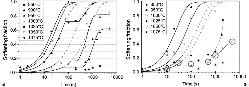
Softening fractions for low C and 0·16Nb steels determined from double deformation tests (ϵ = 0·2, dϵ/dt = 0·5 s−1): temperatures and times at which state of precipitation was investigated by TEM and ICP-MS measurements are indicated by circles on figure
For several of the curves shown in Fig. 18, a temporary recrystallisation stop was observed. This feature has already been observed in the literature.96 Note that the various arrests of recrystallisation in Fig. 18 take place in the interval 30–40 s. This is the time that it took for precipitation to become effective under the conditions of these experiments (such times are closer to 10 s under industrial conditions of strain induced precipitation). Thus, precipitation can only be effective in arresting recrystallisation under rolling conditions where the interpass time is of this order, or at least when the total rolling sequence takes more than 10 s. This signifies that the role of strain induced precipitation is particularly important in reversing mills, such as plate mills. There is clearly insufficient time for strain induced precipitation under strip mill rolling conditions.
However, in the absence of Nb addition, recrystallisation takes place fairly rapidly, as shown in Fig. 11. Here it is evident that recrystallisation has gone to completion in 10 s at 950°C after deformation at 10 s−1 (Fig. 11b ). It is also well under way at this time at lower temperatures (again, these rates are more rapid under industrial, higher strain rate, conditions). It is clear from the softening curves of Fig. 18 that, when Nb is added, recrystallisation only begins at about 10 s. Thus, the presence of Nb in solution is what retards recrystallisation sufficiently in microalloyed steels to prevent its occurrence during rolling sequences that takes a total of 10 s or less, i.e. under strip mill conditions. Nevertheless, it should be mentioned that a strain of 0·2 was employed in the present experiments, while in hot strip mills, strains of more than 1·0 are applied. As demonstrated by Dutta and Sellars113 in their model, the precipitation start time is proportional to the inverse of the strain and so shorter precipitation start times are likely to apply to industrial conditions than suggested by Fig. 11.
In order to evaluate the interaction between recrystallisation and precipitation, the driving force for recrystallisation was calculated114, 115 and compared with the Zener pinning force72 of the precipitates on the grain boundaries. The latter was deduced from a detailed analysis by transmission electron microscopy (TEM) and inductive coupled plasma-mass spectroscopy (ICP-MS), which were performed on the samples identified by the encircled points in Figure 18b .
The precipitate diameter distributions at two interpass times are illustrated in Fig. 19, as determined by TEM on C extraction replicas. The precipitates can be divided into two groups, i.e. precipitates that did not dissolve during reheating and the SIPs. From Fig. 19, it is clear that the distribution of the undissolved precipitates is unimodal, with a lognormal average diameter that remains constant at about 60 nm, as shown by the right hand curve in the various graphs. The distribution of the deformation induced precipitates is also unimodal, with a log normal average diameter that increases with increasing interpass time, as shown by the left hand curve in the different graphs.
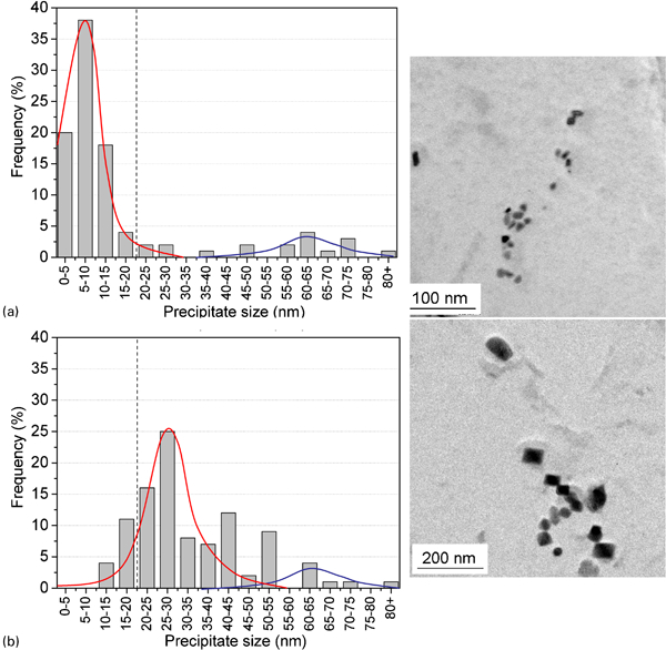
Precipitation state studied by TEM at interpass times t ip of a 10 s and b 1000 s after deformation at 1000°C for 0·16Nb alloy (0·02 wt-%C, 1·50 wt-%Mn, 0·26 wt-%Si, 0·067 wt-%Al, 0·16 wt-%Nb, 80 ppm Ti and 20 ppm N)102
After determination of the weight fraction of Nb precipitates by ICP-MS, the evolution of the Zener pinning force with time was calculated. This was compared with the recrystallisation driving force. Good agreement was observed between the present experimental data102 and a number of theoretical models developed to describe the interaction of precipitation and recrystallisation116, 117 in a quantitative way. It was concluded that, at first (up to 30 s), the driving force for recrystallisation is higher than the Zener pinning force. The average SIP diameter is small, because these precipitates have just nucleated, but since the volume fraction of the precipitates is also small, the resulting Zener pinning force is insufficient to halt recrystallisation. Later (at about 30 s), the Zener pinning force exceeds the recrystallisation driving force because of the growth of the precipitates; consequently, the recrystallised fraction remains constant for a specific time interval. Finally (after 300 s), the Zener pinning force once again drops below the value of the recrystallisation driving force because of the further growth and coarsening of the precipitates and recrystallisation recommences.
The next step was to quantify the solute drag effect and to compare it with the impact of the precipitation effect. As described elsewhere101 in detail, quantification of the solute drag effect was based on literature findings;108, 118 – 120 the results are reproduced here in Fig. 20. The dashed line in this figure represents the retardation of recrystallisation due to the solute drag of Nb in solution. This ‘Nb solute drag line’, which is nearly parallel to the t 0·5 line of the C–Mn reference steel, permits quantification of the magnitudes of the solute drag and precipitation effects directly from the softening time–temperature diagram. Figure 20 shows that, at 50% recrystallisation, i.e. during the growth stage of the recrystallising grains, the dominant mechanism in retarding austenite recrystallisation changes from solute drag, at relatively high temperatures, to precipitation, at temperatures just below the solution temperature, to solute drag once again, at precipitate coarsening temperatures.
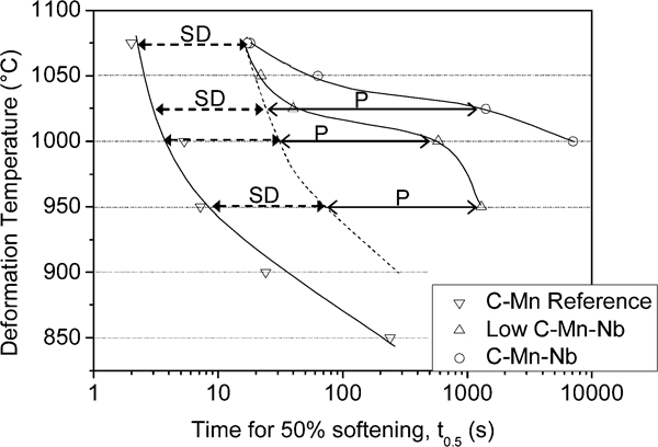
Softening time–temperature diagrams for three experimental steels: plotted is time for 50% softening (SD: solute drag; P = precipitation)101
Influence of ‘new’ alloying elements: Mo, Ni and Cu
In order to compensate for the loss in strength of HSLA steels due to their decreased carbon contents, alloying elements such as Mo, Ni and Cu are often added. The impact of these elements on the mechanical properties (e.g. strength and toughness) and corrosion resistance is fairly well known and has already been discussed above. For example, Bacroix et al. 121 described the increase in strength and toughness produced in low carbon steels by the addition of Mo. This increase was attributed to formation of the low temperature transformation products associated with the addition of Mo. However, the effect of these elements on the austenite recrystallisation behaviour during hot rolling remains to be clarified. Better knowledge of the influence of these elements could help to optimise the addition levels of these elements as well as the rolling schedules for new thick plate products.
The influence of nickel and copper on the recrystallisation behaviour is still far from understood. To date, little literature data could be retrieved on their influence on the T nr and on the recrystallisation kinetics. Cho et al. 122 observed that Ni levels of 0·2 and 0·5 wt-% had no significant effect on the activation energy for recrystallisation in the solute drag region, although some retardation of recrystallisation was identified. Their results confirmed the previous work of Yamamoto et al.,123 who reported a minor increase in recrystallisation rate in decarburised steels containing 1 wt-% Ni. Maehara et al. 124 also evaluated the effect of Ni and Cu and the effect of Cu on the recrystallisation behaviour was reported to be similar to that of Nb, while the effect of Ni was far less.
Some work has already been presented in the literature regarding the role played by Mo. For example, Bouet et al. 125 have described the strong solute drag effect of Mo in Nb bearing transformation induced plasticity steels. Mo addition improved the mechanical properties and also contributed to delaying recrystallisation and precipitation. Furthermore, Pereda et al. 126 reported that Mo in solid solution had a strong retardation effect on dynamic recrystallisation.
In 1985, Wada and Pehlke127 reported that Mo increases the solubility of C and N in austenite. This seems to be linked to the effect of Mo addition in reducing the activities of C and N. Furthermore, Mo also increases the solid solubility of Nb in Nb bearing steels for the same reason. The increased solubilities of C, N and Nb decrease the driving force for Nb(C,N) precipitation.128 Junhua et al. 129 proposed another reason for the retardation of Nb(C,N) precipitation in Mo containing steels: they suggested that Mo increases the carbon diffusion activation energy and decreases the carbon diffusivity in this way. Moreover, Mo may also decrease the diffusivity of Nb. The decreased diffusivities of both C and Nb will delay both the nucleation as well as the growth of Nb(C,N) precipitates. Therefore, the resulting precipitates will be finer and thus more effective in pinning the grain boundaries. As a consequence, recrystallisation in Mo containing Nb steels will be retarded in comparison with Mo free Nb steels, i.e. the T nr will be higher. In conclusion, the presence of Mo in steel appears to influence both solute drag as well as the pinning effect associated with the strain induced precipitates.
A further demonstration of the effect of Mo addition on the recrystallisation kinetics was recently quantified by Pereda et al. 130 In their study, the effect of Mo addition on the T nr of Nb microalloyed steels was investigated by means of multipass torsion tests (ϵ = 0·4, ·ϵ = 1 s−1 and t ip = 30 s). Their results obtained on four different steels are presented in Fig. 21. The 3Nb steel contained about 0·03 wt-%Nb in addition to 0·05wt-%C, 1·6 wt-%Mn and 0·007 wt-%Mo. The 6Nb steel had the same composition but the Nb level was increased to 0·06 wt-%. The Mo containing steels were modified by the addition of 0·31 wt-%Mo.
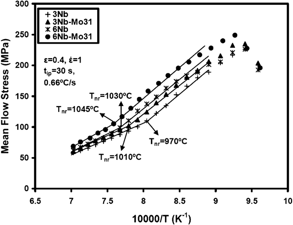
As illustrated in Fig. 21, Pereda et al. 130 showed that, when 0·31 wt-%Mo was added to a 0·03 wt-%Nb steel, the T nr was increased by 40°C, from 970 to 1010°C. However, when the Nb content was increased to levels as high as 0·06 wt-%, the contribution of Mo became less relevant, since the T nr only increased from 1030 to 1045°C. For the experimental conditions and chemical compositions employed in their work, Pereda et al. 130 concluded that the T nr in Mo–Nb steels is mainly determined by the solute drag effect. In the case of the 0·03 wt-%Nb steel, Mo addition produced an additional solute drag effect, which accounts for the significant increase in the T nr in these steels. In the 0·06 wt-%Nb steel, the accelerated kinetics of strain induced precipitation rendered the increase in the T nr due to the solute drag contribution of Mo less relevant.
Summary and outstanding issues
In this work, an overview was presented of the role of the non-recrystallisation temperature T nr, mainly in Nb microalloyed HSLA steels. At first, the general features of HSLA steels and some of their applications were summarised. In a second section, the basics of TMCP were reviewed. Subsequently, current knowledge with respect to the main properties of HSLA steels, namely, their mechanical properties, weldability and corrosion resistance, was addressed briefly; the correlation between their chemical compositions and the associated properties was also outlined. The main focus of this review was on the concept of the non-recrystallisation temperature T nr. The concept of the T nr was defined in the section on ‘The concept of the “non-recrystallisation temperature”’ and the methods employed to determine the T nr from experimental data were described. It has been emphasised that most measurements of this parameter relate to plate mill schedules (i.e. long interpass times) and that new experimental methods must be devised for the determination of the T nr that applies to strip mills, with their much shorter interpass times.
Because the T nr depends on interpass time, it is important to note that a simulation involving 10 or 20 s interpass intervals does not apply to schedules in which the interpass time is in the range of 1 s. The point of importance is that plate or reversing mills involve interpass times that permit carbonitride precipitation to take place. Such precipitation arrests both dynamic and static recrystallisation. By contrast, the much shorter interpass times applicable to strip mills mean that carbonitride precipitation is unable to play a significant role and the inhibition of recrystallisation largely takes place by means of solute drag instead. This phenomenon is also examined in the text. For this reason, simulations employed to determine the T nr should be carried out using the length of interpass interval appropriate to the process of interest.
Nevertheless, ‘strip mill’ simulations are more difficult to perform than ‘plate mill’ simulations, because much less cooling (temperature decrease) can be accomplished during the rather short interpass intervals. Accordingly, several sets of tests must be carried out to cover a given rolling temperature range and average interpass condition. As a result, this type of test is still under development and presents a challenge to the experimentalist.
The physical metallurgical principles behind the T nr were also discussed, since, during TMCP, there is an important interaction between deformation, recovery, recrystallisation, solute drag and precipitation. The T nr is in fact the result of the interaction of all these mechanisms. Finally, the section on ‘Recrystallisation behaviour of HSLA steels’ addressed the influence of the different alloying elements on the recrystallisation behaviour and consequently on the T nr. Apart from carbon and the traditional microalloying elements (Nb, Ti and V), the ‘new’ alloying elements (Mo, Ni and Cu) were also included in the discussion. As mentioned in the text, Nb is the element that most effectively increases the T nr and its role in retarding austenite recrystallisation in HSLA steels has been the subject of considerable interest and discussion over the past 30 years. It is well established that the retardation of austenite recrystallisation in Nb containing steels results from the pinning of austenite grain boundaries and sub-boundaries by niobium carbonitride precipitation as well as by the solute drag effect of niobium atoms in solid solution in the austenite.
Alloying elements, such as Mo, Ni and Cu, are being more frequently added to increase the hardenability, corrosion resistance and strength of HSLA steels. Although their impact on the mechanical properties and corrosion resistance has been widely investigated, their roles in retarding austenite recrystallisation are less well known. Some authors have reported a possible interaction of Mo with Nb carbonitride precipitation, leading to more effective pinning, whereas others have concluded that the solute drag effect is the main mechanism of retardation in these materials and consequently in raising the T nr. To date, systematic data regarding the influence of nickel and copper on the recrystallisation behaviour have not been reported and there is a clear need for further investigation in this field as well as of the Mo–Nb interaction.
Footnotes
Acknowledgements
This work has been supported by the Research Grant 1·5·131·06N of the Research Foundation, Flanders (FWO Vlaanderen). KV wishes to thank the Special Research Fund (BOF), Ghent University, for financial support (BOF10/ZAP/121). SV also acknowledges collaboration with Dr P. Thibaux (OCAS, ArcelorMittal) and the technicians working at OCAS (ArcelorMittal) and the technical staff from the Department of Materials Science and Engineering, Ghent University, for their help with the experiments and sample preparation.