
Abstract
This review aims to summarise the progress in some materials and structures for electromagnetic applications, such as microwave absorption, electric shielding and antenna designs, which have been developed in recent years. Composites with spherical powders for microwave absorption focus mainly on those based on ferrites (especially hexagonal), carbonyl iron and related alloys and various newly emerged nanosized materials. Composites with long conductive fibres as fillers will be summarised, with speical attentions to prediction, measurment and evaluation of their performances. Metamaterials include structures for microwave absorbing applications, tunable materials or structures with reflection or transmission coefficients that are tunable by external magnetic or electric fields, and specially designed structures for microwave absorbing applications, with thickness much smaller than that of conventional composite materials and performances that can be optimised by the physical properties of substrates, and new metamaterials constructed with ferrite cores wound by metallic wire coils that exhibited unique magnetic properties, with extremely high real and imaginary permeability, which are adjustable or tunable by varying their configurations. Magnetodielectric materials, with matching permeability and permittivity, together with sufficiently low magnetic and dielectric loss tangents, with potential applications in antenna miniaturisation, will be discussed.
Introduction
Electromagnetic (EM) materials working at frequencies of 1–18 GHz have been used extensively in commerce, industry and defence applications. Owing to their strong absorption of EM waves, these materials can be used to minimise various EM radiations and interferences. Various materials have been developed for these purposes during the past decades. Noting that there has been only limited reports to summarise the progress of this category of materials,1 this review aimed to provide an overview on the recent progress in composite materials and structures with advanced EM properties for applications in microwave absorption or shielding. They include composites of hexagonal ferrites, composites of metallic magnetic fillers, composites of nanosized particles, composites of conductive fibres, metamaterials with advanced EM properties and magnetodielectric materials with matching permeability and permittivity. Electromagnetic materials and composites based on conductive polymers,2 – 4 design of EM wave absorbers with special structures, optimisation of absorption performances with multilayer structures5 – 8 and so on, are not included in the present review. Interested readers may refer to these cited references and those related references therein.
In the section on ‘Composite materials based on hexagonal ferrites for microwave absorption’, EM properties of composites based on various hexagonal ferrites will be systematically presented. Composites with metallic magnetic particles, especially carbonyl iron, will be presented in the section on ‘Composite materials with magnetic metallic inclusions’. Nanomaterials for EM compostes will be summarised in the section on ‘Composites with nanosized particles’. The section on ‘Microwave properties of composites with long conductive fibrous inclusions’ is to focus on composite materials with conductive fibres. Progress in metamaterials for with interesting EM properties will be described in the section on ‘Metamaterials and structures with advanced EM properties’. The section on ‘Magnetodielectric materials with matching permeability and permittivity’ is to summarise the recent progress in magnetodielectric materials, with potential applications for miniaturisation of antennas of high frequency (HF) and very high frequency (VHF) bands.
Composite materials based on hexagonal ferrites for microwave absorption
Brief introduction
Electromagnetic absorbing property of a material is usually characterised by curves of reflectivity versus frequency. In terms of power reflection of a plane wave reflected from an infinite slab of the material that is backed by a metallic surface, the reflectivity or reflection loss of the material, in terms of normal incidence, which is expressed generally in decibels, can be calculated from μ, ϵ and thickness t of the materials.9
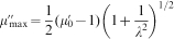
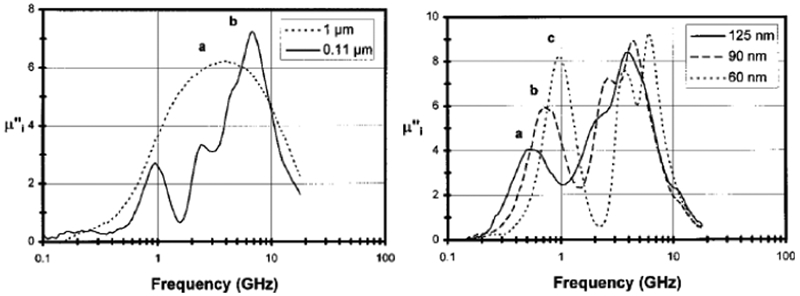
Electromagnetic absorbing materials are always expected to have broad bandwidth, minimum RL and small thickness or light weight. Bandwidth is one of the most important parameters characterising an EM absorbing material in terms of real applications. Theoretical maximum wavelength (or frequency) bandwidth of a magnetic material is closely associated with its static permeability 


Under certain conditions, thickness t of EM absorbing materials is closely associated with their imaginary permeability μ″ (Ref. 11)
Finally, to achieve a low reflection, the impedance matching between the materials and free space is also important. Impedance matching is related to the ratio of μ to ϵ. However, for most EM materials, the value of μ′ is significantly smaller than that of ϵ′ at microwave frequencies. Therefore, it is expected that an increase in μ or a decrease in ϵ could make the ratio of these two parameters closer to unity.
Electromagnetic absorbing materials (or composites) are often prepared by mixing magnetic or dielectric particles (also known as fillers or inclusions, both of which are taken to be the same throughout this review, unless otherwise stated) and polymers, according to certain volume concentrations p of the particles. It has been shown that the performance of EM composites depends strongly on magnetic and dielectric properties of the particle inclusions. In most cases, the interactions between the particles also play an important role in determining performances of the composites.
Magnetic particles used to fabricate EM composites are usually divided into two types, namely ferrite and metal or alloy particles. As compared to metallic and alloy particles, ferrite particles have many important advantages, such as low permittivity, high resonance frequency, high resistivity, low density and good chemical stability. Therefore, ferrite composites are promising candidates for EM absorbing materials with broad bandwidth, especially as the matching layer between EM material and free space in multilayer configurations. This section is used to present a thorough overview on magnetic, dielectric and EM properties of composite materials with ferrites as inclusions, with those made with metallic fillers being discussed later.
In general, there are three types of ferrites, namely spinel, garnet and barium (or hexagonal) ferrites, according to their crystal structures. Properties and applications of these ferrites are briefly summarised in Table 1. Most spinel ferrites have large static permeability, which have been extensively used in electric and electronic technologies at radio frequency (RF), VHF and ultrahigh frequency (UHF). The most important characteristics of garnet ferrites include high gyromagnetic property and very low magnetic and dielectric loss tangents. Hence, they are very useful in reciprocal and non-reciprocal microwave devices. However, these two ferrites are not suitable to be used as EM composites at GHz frequencies, owing to their relatively low resonance frequencies. As a result, we will focus on hexagonal ferrites and their composites that have advanced microwave absorbing performances.
Main properties of three types of ferrites (
is static permeability, f
R is resonance frequency and ρ is resistivity)

Crystal structure, static and high frequency magnetic properties of hexagonal ferrites have been reviewed by Smit and Wijn,12 Kojima13 and Sugimoto.14 All hexagonal ferrites have hexagonal structure that, for a unit cell, comprises three blocks: S blocks (spinel block) without barium ions, R blocks (hexagonal block) comprising barium ions and two oxygen layers, and T blocks (hexagonal block) comprising barium ions and four oxygen layers. According to the numbers and arrangements of the three types of blocks, hexagonal ferrites are classified into M-, W-, Y-, Z-, X-, and U-types. Among them, M-type hexagonal ferrite has the simplest structure, with two S and two R blocks, which are arranged in the sequence of RSR*S*, where the asterisk indicates a rotation by 180° around the c-axis for the corresponding block.
Low hexagonal crystal symmetry of hexagonal ferrites, as compared to the cubic symmetry of spinel or garnet ferrites, leads to their significantly high magnetocrystalline anisotropy of K 1≈106 erg cm−3, which is one to two orders of magnitude larger than that of spinel or garnet ferrites. Owing to their large anisotropy, besides as permanent magnetic materials and perpendicular recording materials, hexagonal ferrites have also been widely used in microwave reciprocal and non-reciprocal devices or EM absorbing materials at GHz and even millimetre wave frequencies, because of their resonance frequencies that can be as high as 100 GHz.15
According to easy magnetisation directions, the hexagonal ferrites with hexagonal structure can be divided into two types, namely c-axis and c-plane anisotropy, as shown in Fig. 1. They correspond to the easy magnetisation along c-axis and in c-plane respectively. For c-axis anisotropy, the magnetic field required for rotation of magnetisation vectors from [001] to [00
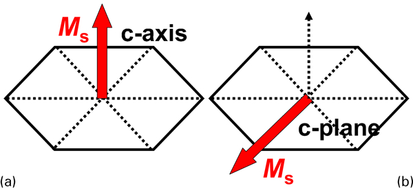
Schematic diagrams of a c-axis and b c-plane anisotropy of hexagonal ferrites
The anisotropy fields, either H
a or Hθ
and Hφ
, are closely related to the static real permeability 


Hexagonal ferrites with c-axis anisotropy, in fact, are hard magnetic materials, owing to their large H
a. Based on equation (3), H
a determines both 


However, hexagonal ferrites with c-plane anisotropy are soft magnetic materials due to their very small Hφ
. According to equation (4), small Hφ
can lead to large 

Theory
The dependence of complex permeability on frequency f is known as permeability spectrum, which characterises high frequency magnetisation properties of a material. In general, the spectrum can be divided into five zones. They are low frequency spectrum (<104 Hz), midfrequency spectrum (104–106 Hz), high frequency spectrum (106–108 Hz), microwave spectrum (108–1010 Hz) and extremely high frequency spectrum (>1010 Hz). Neglecting the loss due to eddy current and skin effect, the permeability spectrum at different frequency bands exhibits different characteristics and dominant mechanism. At the low frequency band, μ′ is practically constant, while μ″ is close to zero. At the midfrequency band, it is possible to observe magnetic internal friction peak, dimensional resonance or magnetomechanical coupled resonance, which has their origin in the size of the materials.17 At the high frequency band, owing to domain wall resonance and relaxation, μ′ decreases while μ″ increases.18 At the microwave band, natural resonance is the dominant mechanism, and possibly gives rise to negative μ′, with a resonant peak observed for μ″.19 At the extremely high frequency band, internal exchange field is the main contributor. Detailed high frequency magnetisation and permeability spectra have been described in Refs 20–22.
At high frequency and microwave bands, the resonances are mainly controlled by two mechanisms, namely domain wall and natural resonances, which will be discussed as follows.
Resonance mechanisms
Domain wall resonance
Under an ac magnetic field, 
Natural resonance
Magnetisation vector precesses about the static magnetic field. The energy is absorbed strongly from the ac transverse field when its energy is equal to the precessional frequency. This is known as ferromagnetic resonance, which was first observed by Grifiths in 1946.25 The precession equation of M was first proposed by Landau and Lifshitz in 1935.27
Ferromagnetic resonance without an applied magnetic field H 0 is generally known as natural resonance. Without H 0, the unsaturated magnetisation vectors are located along easy magnetisation directions. For polycrystalline materials, the directions of crystal grains are different and are randomly distributed in all directions of space.
Permeability spectra of natural resonance
Permeability spectra are determined by three parameters, namely static real permeability μ
0, intrinsic resonance frequency f
r and damping coefficient λ. μ
0 (or 
Intrinsic resonance frequency fr
f
r, in general, is determined by the anisotropy field and demagnetising field H
d.19,28,29 For particles with single domain, if H
a or Hθ
is along z axis, f
r is expressed as

For particles with different shapes, the values of f r calculated based on equations (5) and (6) are listed in Table 2. As compared to spherical particles, the particles with bar-like shape have higher f r, while the particles with disc-like shape have lower f r. If particles are spherical with N x = N y = N z, f R will be simplified to equations (3) and (4).
Intrinsic resonance frequency f r, for c-axis and c-plane anisotropy, of particles with various shapes
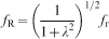
Damping coefficient λ
The resonance frequency obtained from permeability spectra f
R is defined as the frequency corresponding to maximum imaginary permeability, 
For natural resonance, the maximum of μ″(f) is given by32


Two types of dispersions
Dispersion types of permeability spectra (or shapes of the spectra) are related to λ. In practice, there two types of spectra, namely resonance-like and relaxation-like dispersions, according to the magnitudes of λ. Small λ leads to resonance-like dispersion. On the other hand, for large λ, the permeability spectra demonstrate a relaxation-like dispersion. Composites with relaxation-like dispersion are often of broad band absorption.
Effects on physical properties of ferrite composites
Electromagnetic composites usually consist of ferrite particles and polymers, like epoxy resin. Therefore, magnetic properties of EM composites are related not only to the properties of the ferrite itself, but also to the interaction among the ferrite particles through the polymer matrix. Naturally, composites have some particular properties which are significantly different from their counterparts of bulk ferrites. Effects on physical properties of ferrite composites are discussed as follows.
Substitution effect
Hexagonal ferrites, except Y-type one, have c-axis anisotropy. Based on the above discussion, in order to obtain large 

Dependence of anisotropy types, anisotropy fields Hθ and resonance frequencies f R on Co substitutions in Ba3CoxZn2−xFe24O41 ferrites or their composites
Besides Co ion, non-magnetic ion substitutions can also modify the magnetocrystalline anisotropy of hexagonal ferrites. The magnitude of anisotropy depends on the distribution of the ions at inequivalent sites.35 – 37 Al3+ and Ga3+ ions preferentially occupy the 12k sites.38,39 Substitution of Al3+ and Ga3+ ions for Fe3+ ions enhances the c-axis anisotropy of hexagonal ferrites, thus increasing their resonance frequency f R.38 – 40 On the other hand, complex ions, such as Ti4+Mn2+, Zr4+Zn2+ and Sn4+Zn2+, tend to weaken the c-axis anisotropy and, consequently f R is shifted to relatively low frequencies.41 – 44
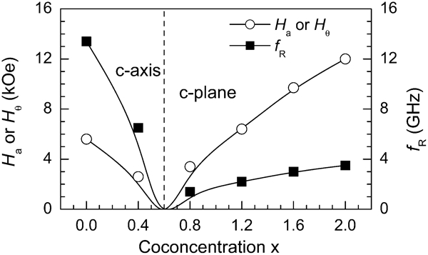
It is found that, to a good approximation, f R of hexagonal ferrites or their composites is approximately proportional to H a for c-axis anisotropy15 and to the out-of-plane anisotropy field Hθ for c-plane anisotropy45 respectively, as shown in Fig. 3. Therefore, f R can be controlled by the anisotropy field, which is closely associated with ion substitutions.
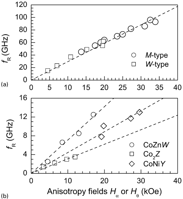
Relationship between resonance frequency f R and anisotropy fields a H a and b Hθ respectively, for composites of hexagonal ferrites with c-axis and c-plane anisotropies
The distributions of non-magnetic ions on various sites are related not only to the magnetocrystalline anisotropy, but also to saturation magnetisation M
s. Among various non-magnetic ions, Zn ion has been confirmed to preferentially occupy the spin-down sites of M-,43,46,47 W-,48,49 Y-,50,51 and Z-types hexagonal ferrites.52 In addition, substitutions of Zn for Fe3+ ion also weaken the anisotropy field, H
a or Hφ
. The enhancement in M
s and the reduction in H
a or Hφ
are benefit to an increase in 

Doping effect
In general, a small amount of doping oxides (usually <1·0 wt-%) is not able to significantly modify the intrinsic properties of hexagonal ferrites, such as saturation magnetisation and magnetocrystalline anisotropy. However, microstructure and magnetic domain of the ferrites can be modified by the doping of oxides with a low concentration. The microstructure and magnetic domain characteristics are also decisive factors to achieve special properties, for example, low coercivity H c and high electric resistivity. Various oxides have been used as dopants to optimise the static magnetic properties and microstructures of spinel ferrites53 – 56 and hexagonal ferrites.45,57
It has been shown that doping of oxides can increase 


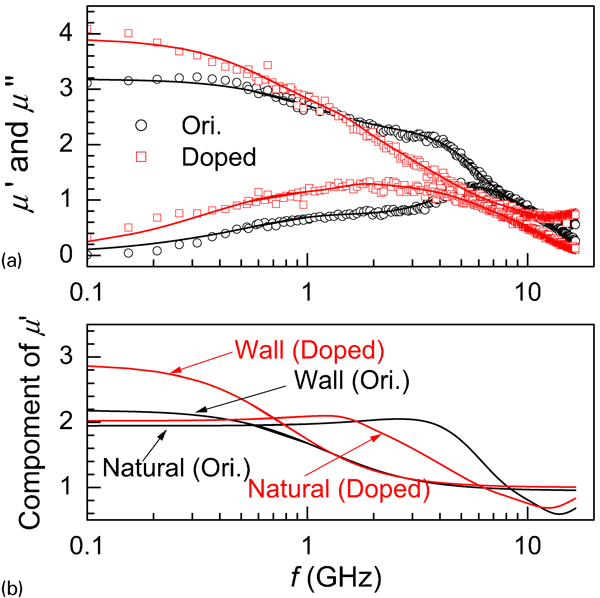
a measured (symbols) and curve fitted (solid lines) permeability spectra and b curve fitted μ′(f) of natural and wall components for composites of BaCoZnFe16O27 undoped and doped with 0·5 wt-%CaO
Based on the rotation model, static permeability is related to M
s and in-plane anisotropy field Hφ
, i.e. (


Relationship between (
Volume concentration effect
High frequency magnetic properties of composites are also closely related to volume concentration of the ferrite particles p. Composites have two important characteristics, which are significantly different from those of their bulk materials. First, 


Dependence of a


Several models, such as Bruggeman and Maxwell Garnett mixing rules, magnetic circuit model,64
–
66 simulation EM energy,67 magnetic percolation model68 and two-particle model,69 have been proposed to predict the dependences of 

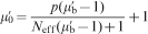
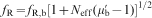

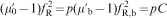


Figure 6 also shows the predicted dependence of 


Shape effect
Based on Maxwell–Garrett mixing law (equation (11)), 


Relationship between


It has been shown that doping of V2O5 can significantly modify high frequency magnetic properties of the composites made with BaCoZnFe16O27, through the modification in shape of the ferrite particles.31 As shown in Fig. 8, 


Permeability spectra for composites of BaCoZnFe16O27 without and with the doping of V2O5, (inset) particle shape after doping
Size effect
For metallic fillers, size of the particles, in general, must be smaller than a certain value, due to the presence of eddy effect. In this regard, because of their very high electric resistivity (104–1010 Ω cm), ferrite fillers have no problem of eddy effect. However, ferrite particle sizes still play an important role in determining permeability values of their composites. For example, experimental results showed that 

Static real permeability
As mentioned earlier, 


In addition, M s and H c are also closely associated with the size d of the particles. M s almost linearly decreases from 55·3 emu g−1 for d = 10 μm to 49·4 emu g−1 for d = 20 nm. H c increases from 45 to 450 Oe correspondingly. The decrease in M s and the great increase in H c with decreasing particle size are also responsible for the decrease in static permeability.73
Damping effect


Dependence of

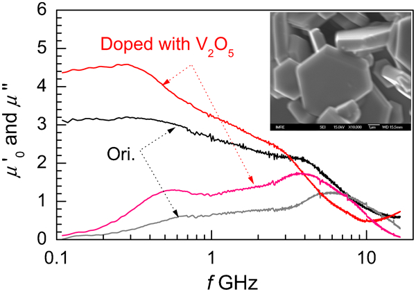
An example is shown in Fig. 11.74 The curve fitting results indicate that λ is significantly different between the two composites (I and II), where I is CoTi substituted Co2
Z and II is Co2
Z ferrite particles respectively. λ of composite I is only 0·74, while that of composite II is 1·36. Although the two composites have almost same value of 


Permeability spectra and their fitted curves for composites I and II
Dispersion effect
According to the magnitude of damping coefficient λ, permeability spectra of composites can exhibit either relaxation-like dispersion (relatively large λ) or resonance-like dispersion (relatively small λ).
The permeability spectra of hexagonal ferrite composites with c-plane anisotropy exhibit usually relaxation-like dispersion. Due to relatively large 


As an example, typical permeability spectra with resonance-like dispersion are shown in Fig. 12. The composite was made with MnTi substituted M-type barium ferrite with c-axis anisotropy at p = 0·35. Although (


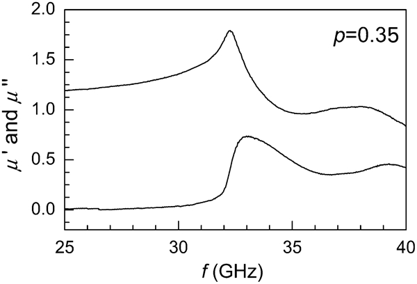
Permeability spectra with resonance-like dispersion for M-type ferrite composite with c-axis anisotropy
High frequency and microwave absorbing properties of barium ferrite composites
As stated earlier, high frequency magnetic properties of ferrite composites are significantly different from those of their corresponding bulk ferrites, because there exist interactions among the ferrite particles through the polymer matrix. The most significant differences include greatly decreased 

M-type barium ferrite composites
In general, M-type hexagonal ferrite, BaFe12O19, are hard magnetic materials with c-axis anisotropy. Its saturation magnetisation, M
s is 4·8 kGs, magnetocrystalline constant K
1 is 3·2×106 erg cm−3 and anisotropy field, H
a is 16·8 kOe.13,76 Owing to its high c-axis anisotropy, its static real permeability 
Co2+, Ru2+ and Ir4+ ions, which are able to provide very large c-plane anisotropy, are often used to substitute for Fe3+ ions to modify the anisotropy of BaFe12O19 from c-axis to c-plane,79
–
82 so as to achieve relatively large permeability 


Ferromagnetic resonance has shown that f R decreases from 46 to 18 and 10 GHz respectively, for the M-type hexagonal ferrites substituted by CoTi and Sc with x = 1·6.86 High frequency magnetic properties and EM absorbing performances, of MnTi,87 – 89 ZnZr and ZnSn90 substituted M-type hexagonal ferrites and their composites, have been studied. For example, the composites derived form BaFe12−2xMnxTixO19 with x = 1·5 and 2·0 had broad bandwidths of 14·1 to ∼20 GHz and 7·4–12 GHz, at thickness of 1·6 and 2·7 mm respectively, for RL≤−20 dB.87,88
Figure 13 shows permeability spectra of the composites made with MnTi substituted BaFe12−2xMnxTixO19 (x = 1·4, 1·6 and 1·8) ferrites. The spectra exhibit resonance-like dispersions with damping coefficient λ, of only ∼0·1, which is much smaller than λ of about 1–1·5, generally observed in composites with permeability spectra of relaxation-like dispersion. Away from resonance range, 

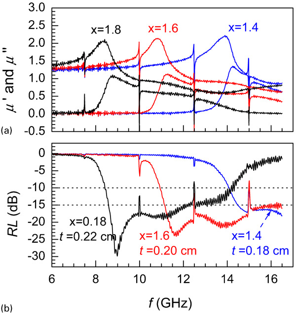
a permeability spectra and b attenuation characteristics of BaFe12−2xMnxTixO19 ferrite composites (p = 0·5) with substitutions x = 1·4, 1·6 and 1·8 (Ref. 89)
Figure 13b shows that the composites with resonance-like dispersion can exhibit low reflection loss RL with considerably broad bandwidth. The frequency bands of RL≤−15 dB cover from 8·5 to 13 GHz and 11 to 16·5 GHz, at thickness of 0·22 and 0·18 cm respectively, for x = 1·8 and 1·6. These composites are good candidates for EM attenuation at K u bands.89
W-type barium ferrite composites
The hexagonal ferrites, Me2
W, i.e. BaMe2Fe16O27 (Me = bivalent metallic ions), have the highest Curie temperatures T
c and the highest saturation magnetisation M
s at room temperature, which are related to their highest ratio (0·62∶0·38) of magnetic ions to oxygen ions. Their intrinsic magnetic properties are listed in Table 3.12 Fe2
W, Ni2
W and Zn2
W are of c-axis anisotropy, with large c-axis anisotropy fields. The resonance frequency, f
R of Ni2
W ferrite can reach as high as 36 GHz,91 which is well consistent the value derived from the anisotropy field of 12·5 kOe. Co substitution was used to modify the anisotropy from c-axis to c-plane. From ferromagnetic resonance92 and magnetic measurement of aligned samples,93 Co2
W is c-plane anisotropy with an out-of-plane anisotropy, Hθ
of 21·2 kOe. Since Zn substitutions are also able to increase 
Saturation magnetisation 4π M s, Curie temperature T c, anisotropy constant K 1 or K 1+2K 2, and anisotropy H a or Hθ of Me2 W (BaMe2Fe16O27) ferrites12
High frequency magnetic properties of BaCoxZn2−xFe16O27 have been comprehensively studied by Paoluzi et al.
94 and Li et al.
93 Representative experimental results are listed in Table 4.93,95 X-ray diffraction (XRD) patterns of the aligned samples showed that the transition of magnetic anisotropy occurred at x≈0·7, which was also confirmed by the dependence of coercivity H
c on x.93 With Co substitutions from x = 1 to 2, 


Static magnetic properties of BaCoxZn2−xFe16O27 hexagonal ferrites (M s is saturation magnetisation, H c is coercivity, and H a or Hθ are anisotropy fields for c-axis or c-plane anisotropy)93
As mentioned in the section on ‘Doping effect’, doping of hexagonal ferrites with oxides can increase 

Static magnetic properties of BaCoZnFe16O27 ceramics, doped with various oxides, including 0·5 wt-%CaO, Bi2O3, and 1·0 wt-% CuO, MnO2, IrO2, RuO2, Nb2O5 and V2O5, and high frequency properties of their corresponding composites, where M
s is saturation magnetisation, H
c coercivity,
and
are static real and maximum imaginary permeability,
and
are real permittivity at 0·5 and 16·5 GHz58,97,98
For the composites made with the undoped ferrite, 


From Table 5, the doping of V2O5 (perhaps Nb2O5 also) is very interesting.31 


Attenuation characteristics of BaCoZnFe16O27 composites, where 0 and 1 denote composites of ferrites undoped and doped with 1 wt-%V2O5 respectively
The effect of CoZn substitution, combined with the doping of 1 wt-%V2O5, on high frequency magnetic properties and attenuation characteristics of the composites of BaCoxZn2−xFe16O27 with x = 0 to 2·0, has been studied by Li et al. and Wu et al.
102
–
104 According to permeability spectra, the composites can be divided two groups. The ferrites with x = 1·0, 1·3 and 1·5 have c-plane anisotropy and permeability spectra of their composites exhibit relaxation-like dispersion, as shown in Fig. 15. 
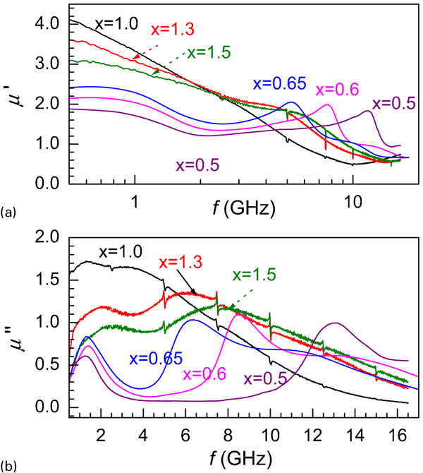
a real and b imaginary permeability spectra of composites with BaCoxZn2−xFe16O27+1 wt-%V2O5 at p = 0·5
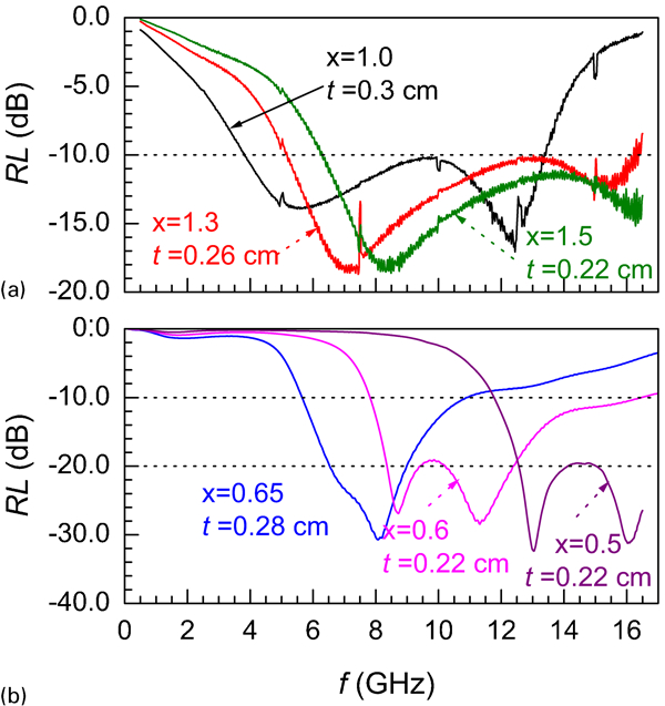
Attenuation characteristics of BaCoxZn2−xFe16O27+1 wt-%V2O5 composites with p = 0·5
On the other hand, the ferrites with x = 0·5, 0·6 and 0·65 are of c-axis anisotropy, and permeability spectra of their composites have resonance-like dispersion,104 as shown in Fig. 15. 


Y-type barium ferrite composites
Most Me2 Y (except Cu2 Y) hexagonal ferrites, Ba2Me2Fe12O22, have c-plane anisotropy, which is attributed to their special crystal structure: 3×(ST) blocks without any R block. It is known that the 2b or 2d sites in the R block contribute to much larger c-axis magnetocrystalline anisotropy than other sites, due to their large asymmetry. Without any R block, Y-type ferrites, in general, are of c-plane anisotropy even without the presence of Co ions.12
Static magnetic parameters of Me2 Y are listed in Table 6. As compared to other types of hexagonal ferrites, Me2 Y ferrites have relatively small M s and low Curie temperature T c. For example, T c of Zn2 Y is only 130°C. The highest T c of 390°C is found in Ni2 Y.12 However, owing to its very small Hφ of ∼1 Oe, Zn2 Y is still able to show large permeability.12,16
High frequency and attenuation properties of Zn2
Y ferrites and their composites have been reported by various researchers.105
–
110 Permeability spectra of single crystal Zn2
Y ferrite were measured over 0·1–10 GHz by Obel et al.,105 with 


Tables 7–9 list static and high frequency magnetic properties of (CoZn)2
Y, (NiZn)2
Y and (CoNi)2
Y hexagonal ferrites and their composites.111 The permeability spectra of all composites comprise two or three components from natural and wall resonances. With Co substitutions, the anisotropy field, Hθ
increases, and, therefore, 


Saturation magnetisation M
s, coercivity H
c, anisotropy fields Hθ
, static permeability
, natural and wall resonance frequency f
R,N and f
R,W, of the Ba2CoxZn2−xFe12O22 ferrites and their composites with p = 0·5 (Ref. 111)
Saturation magnetisation M
s, coercivity H
c, anisotropy fields Hθ
, static permeabilit,
, natural and wall resonance frequency f
R,N and f
R,W of Ba2NixZn2−xFe12O22 ferrites and their composites with p = 0·5 (Ref. 111)
Saturation magnetisation M
s, coercivity H
c, anisotropy fields Hθ
, static permeability
, natural and wall resonance frequency f
R,N and f
R,W of Ba2CoxNi2−xFe12O22 ferrites and their composites with p = 0·5 (Ref. 111)
In terms of EM attenuation performances, Cu substituted Y-type ferrite composites are the most interesting, as reported in Ref. 74. Permeability spectrum of the Ba2CuZnFe12O22 composites consists of natural and wall resonance components with roughly equal weight. The spectrum is of a typical relaxation-like dispersion, with 


Permeability spectra and attenuation characteristics (inset) of Ba2CuZnFe12O22 composites with p = 0·5 (Ref. 74)
For Ba2CuZnFe12O22 ferrite composite, permeability spectrum, with 

a permeability spectra and b attenuation properties of Ba2CuZnFe12O22 composites with p = 0·5 (Ref. 74)
Z-type barium ferrite composites
Among the soft magnetic hexagonal ferrites, Z-type ferrites are the most attractive. Static magnetic properties of representative Z-type ferrites are listed in Table 10.12 Co2Z ferrite, Ba3Co2Fe24O41, is one of most important microwave ferrite materials, with relatively large permeability. Its saturation magnetisation is 51 emu g−1 at room temperature and Curie temperature is 690 K. At room temperature, Co2Z ferrite has c-plane anisotropy with a large out-of-plane anisotropy field, Hθ
of 12 kOe and a small in-plane anisotropy field, Hφ
of ∼0·12 kOe.16,112 Its static real permeability 
Saturation magnetisation 4π M s, Curie temperature T c, anisotropy constant K 1+2K 2 and anisotropy field Hθ of Me2Z (Ba3Me2Fe24O41) hexagonal ferrites12
Great efforts have been made to improve the high frequency properties of Co2Z ferrites, especially in order to increase its 


Zn2+Ti4+ (without Co ion) substitutions resulted in Z-type ferrites with c-axis anisotropy. Although 


Besides the typical ceramic technique, various other processes have been used to prepare Co2Z hexagonal ferrites. For instance, the addition of Bi–Zn–B glass can shift the resonance of Co2Z to higher frequencies.125 Co2Z prepared by using hot pressing technique has a resonance frequency of 2·5 GHz.126 Almost phase pure Co2Z with 


As compared to bulk Co2Z ferrites, 


Static magnetic properties of CoZn substituted Z-type hexagonal ferrites, Ba3CoxZn2−xFe24O41, are listed in Table 11. By CoZn substitution, 


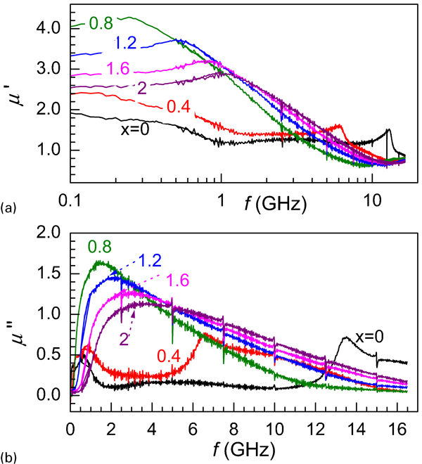
a real and b imaginary permeability spectra of Ba3CoxZn2−xFe24O41 composites with p = 0·5
Static magnetic properties of Ba3CoxZn2−xFe24O41 hexagonal ferrites, where M s is saturation magnetisation, H c is coercivity, and H a or Hθ are anisotropy fields for c-axis or c-plane anisotropy34
Relatively low f
R is a main drawback of the CoZn substituted Z-type ferrite composites. The highest f
R is only ∼3·0 GHz in the sample with the maximum Co concentration of x = 2. To further elevate f
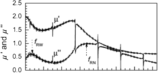
R, substituting for Fe3+ with Co2+Ti4+ to form Ba3Co2+xTixFe24−2xO41 was proposed. Representative permeability spectra and attenuation characteristics are shown in Fig. 20.32 As CoTi substitutions are increased from 0 to 0·5 and 1·0, 


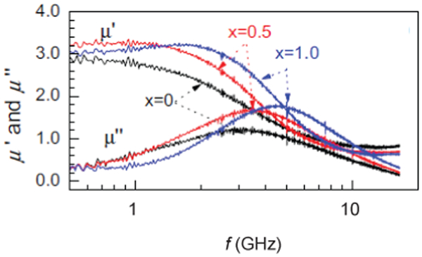
a permeability spectra and b attenuation characteristics of Ba3Co2+xTixFe24−2xO41 ferrite composites with p = 0·5
Using Ru4+ or Ir4+ instead of Ti4+ ions can significantly increase f
R, because the two ions contribute a very large magnetocrystalline anisotropy. Experimental results have shown that, f
R of Ba3Co2+xTixFe24−2xO41 ferrite composites is increased from 2·5 to 4·2 and 11·5 GHz, as RuCo substitution x is varied from x = 0 to x = 0·2 and 0·8. However, 

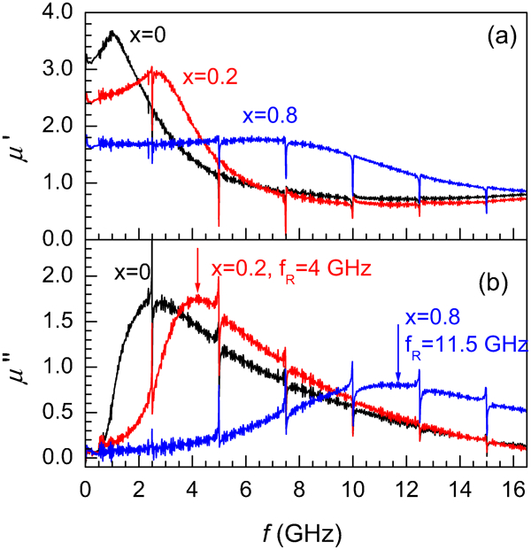
a real and b imaginary permeability spectra of Ba3Co2+xRuxFe24−2xO41 ferrite composites with p = 0·5 (Ref. 74)
Molten salt technique has also been used to improve the properties of ferrites through controlling over their particle morphologies. Example of molten salt method was reported by Lin et al.,129 using NaCl as flux. Co2
Z ferrite powder prepared by this method had particles with hexagonal plate shapes of ∼40 μm. The large and plate shape Co2
Z particles as fillers lead to composite with increased 


Similar to W-type ferrite, doping of oxides is also able to increase 


High frequency parameters
,
and f
R, and ϵ
0·5 and ϵ
16·5 at frequencies of 0·5 and 16·5 GHz, of Co2
Z ferrite composites, where Co2
Z ferrites were doped with various oxides130
High frequency parameters
,
and f
R, and ϵ
0·5 and ϵ
16·5 at frequencies of 0·5 and 16·5 GHz, of Co2
Z ferrite composites, where Co2
Z ferrites were doped with various oxides130
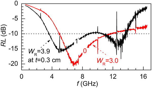
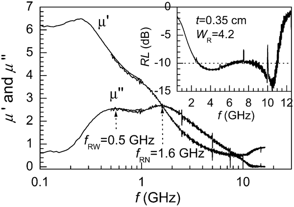
Figure 22 shows permeability spectra and EM attenuation characteristics of the composites made with the 1 wt-%TiO2 doped Co2 Z ferrite. The frequency band for RL≤−10 dB is from 3 to 12·5 GHz, corresponding to W R of 1∶4·2, at a thickness of t = 0·3 cm. For a comparison, the undoped Co2 Z ferrite composite exhibits W R of 2·4–3·1. The TiO2 doped Co2 Z composite is a good candidate EM attenuation material with broad bandwidth and thin thickness at S, C and X microwave bands.74

a permeability spectra and b attenuation characteristics of the composites made of Co2
Z ferrite (p = 0·5) doped with 1 wt-%TiO2: inset shows
Composite materials with magnetic metallic inclusions
Magnetic metals and metallic alloys have composed the second main group of candidates as inclusions to fabricate composite materials with advanced EM performances. This section serves to present an overview on the progress in EM composite materials based on metallic magnetic fillers, with a specific attention being paid to carbonyl iron. Focuses will be relationships between EM properties, as well as microwave attenuation performances, and types of carbonyl iron, thermal stability, concentration effect, of composite materials made of commercially available carbonyl iron powders. Moreover, strategies that have been employed to enhance EM performances of these composites will be introduced. Nanosized magnetic metallic fillers will be presented in next section, together with other nanosized fillers, that have been developed to fabricate EM composite materials. There are also other differences in contents between this section and the next section. For example, carbon nanotubes (CNTs) as additives to improve the properties of composites of carbonyl iron are included in this section,169,170 while they will be described in the next section if CNTs with metallic particles inside the tubes are used as fillers of composites.235 – 238 It is necessary to state that theoretical investigation on complex permeability and permittivity of the composite materials with magnetic metallic inclusions will not be included in the present review, which can be found in the open literature.131 – 135
Carbonyl iron
Carbonyl iron powders produced by various methods might differ in such parameters as chemical composition, particle size, size distribution, hysteresis loss coefficient, etc. The state-of-the-art technology for preparation of carbonyl iron powders is thermal decomposition of iron pentacarbonyl Fe(CO)5 in the presence of ammonia in the temperature range 500–600 K. Ammonia is used to regulate the ratio of carbon and nitrogen combined with iron and to ensure the formation of particles with spherical shapes. The absence of ammonia leads to powders free of carbon, which affects their EM properties.
Although commercial carbonyl iron powders can be used directly to prepare composites with various polymers,136,138,140,141,143 different products from different sources could lead to composites with different EM performances. This is because the final properties of a composite are closely related to the characteristics of the powder used. The determining factors include chemical composition, morphology, particle size, size distribution, surface profile, etc. For example, owing to the high electric conductivity of metallic powders, particle size plays a significant role in determining the microwave properties of the final composites. The particle size is closely related to skin depth δ, which is defined as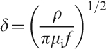
Different from those of ferrites, composites made with metallic magnetic powders have another problem of threshold percolation due to the high conductivity of the fillers. Generally, percolation volume concentration of a composite with spherical conductive fillers is ∼33%. Above this percolation concentration, the composite becomes conductive and thus has poor EM attenuation capability, due to the worsened impedance matching caused by the increased permittivity. Relationships between concentration and EM properties, as well as microwave attenuation performances, of carbonyl iron composites, are demonstrated as follows.139
Figure 23 shows complex permittivity curves of the composites with various volume concentrations of carbonyl iron powder. Permittivity values of the composites increased gradually with volume concentration of the metallic filler. Real part of permittivity (at 10 GHz) increased from 4·9 for the 11·6 vol.-% sample to 18 for the 42·6 vol.-% one, while average imaginary part increased from ∼0·2 to ∼0·8. Both real and imaginary parts had no significant variation with frequency in the frequency range studied. These observations are similar those widely reported in the open literature.141,143
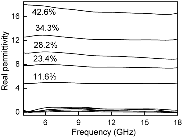
Complex permittivity spectra of composites with different volume concentrations of commercial carbonyl iron powder139
Complex permeability curves of the composites are shown in Fig. 24. Real parts of permeability decrease almost monotonically with increasing frequency, while imaginary parts have observable peaks that shift towards low frequency with increasing concentration of carbonyl iron. Magnetic loss tangent of the composites, as a function of frequency, are plotted in Fig. 25. The always increase in magnetic loss tangent was due to the magnetic retardation.143
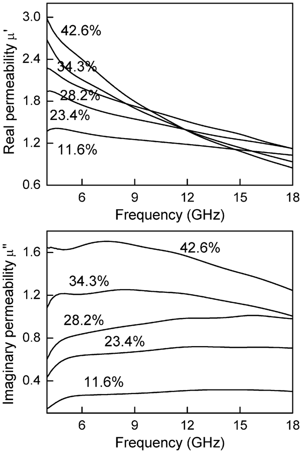
Complex permeability spectra of composites with different volume concentrations of commercial carbonyl iron powder139
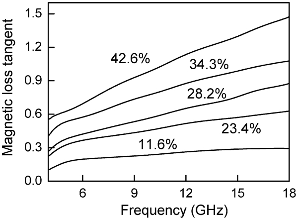
Magnetic loss tangents of composites with different volume concentrations of carbonyl iorn powder as function of frequency139
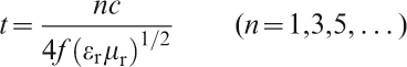
Reflection loss curves with frequency of the composites are illustrated in Fig. 26. Resonance frequency and minimum reflection loss RL of the composites, as a function of thickness, are summarised in Fig. 27. For a given composite with a given concentration of carbonyl iron, the frequency of the minimum reflection loss shifts towards low frequency with increasing thickness. At a given thickness, such frequency decreases with increasing concentration of carbonyl iron (upper panel in Fig. 27). In other words, the frequency of the minimum reflection loss decreases with increasing μ and/or ϵ. This can be explained by the so called quarter wavelength (λ/4) condition141,142
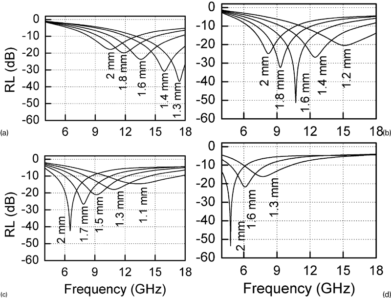
Reflection loss curves of composites with different volume concentrations of carbonyl iron powder139
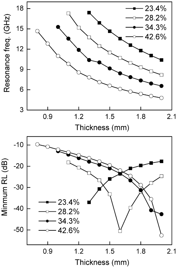
Resonance frequency and minimum reflection loss RL of composites with different volume concentrations of commercial carbonyl iron powder as function of thickness139
The reflection loss is not simply proportional to thickness of the composite. Generally, with increasing thickness, the absolute value of minimum reflection loss first increases, reaches to a maximal and then decreases. Taking the sample with 28·2 vol.-% carbonyl iron as an example, as its thickness is increased from 1·1 to 1·6 mm, the absolute minimum reflection loss increases from 18·2 to 50·6 dB (Fig. 26b
). It is maximised at 1·6 mm and gradually decreases with further increasing thickness (bottom panel in Fig. 27). If t
m is used to represent the thickness at which the maximum absolute reflection loss is achieved, t
m increases with further increasing thickness. The frequency bandwidth of RL<−10 dB is also not monotonically varied with thickness of the composites. These observations can be understood by using impedance matching degree Γ, which is defined as
Strategies to improve EM performances of magnetic metallic composites
High frequency behaviour of metallic magnetic materials can be described by Snoek’s law70
High energy ball milling is one of the most promising techniques that has been used to produce flaky metallic magnetic particles. An outstanding example was reported by Han et al. 147 The authors started with a commercial carbonyl iron powder that had a particle size distribution of 1–5 μm. The commercial powder consisted of nearly perfect spherical particles. Mechanical treatment was conducted by using a planetary ball mill, with a ball-to-powder weight ratio of 25∶1, in the presence of n-hexane. Two milling speeds (200 and 500 rev min−1) were used. After milling for 8 h at 200 rev min−1, part of the spherical particles was deformed into flaky ones, with a typical thickness of ∼500 nm. 500 rev min−1 milling for 8 h led to almost complete deformation of the particles into thin flakes with a thickness of ∼100 nm. The thickness of both the milled powders is smaller than the skin depth of pure carbonyl iron (∼1 μm over 1–5 GHz). A slight reduction in saturation magnetisation and increase in coercive field occurred due to the high energy ball milling, which was attributed to the fact that milling could have introduced disordering, strains and defects in the powders. The milled powders more easily reached saturation magnetisation than the unmilled one, which implied that the former had a higher static permeability than the later. Composites with 50 vol.-% concentration were prepared by using paraffin as holding matrix. The flaky characteristics of the milled powders were also identified by Mossbauer spectra.
Complex permeability spectra of the composites made with the unmilled and milled carbonyl iron powders are significantly different.147 Real parts of permeability of the composites with the milled powders were ∼8·6 at 0·1 GHz, which was higher than that of the composite derived from the unmilled powder (∼6·1) by ∼42%. Significant increase in imaginary part was also observed in the composites with the milled powders. Moreover, the composites of milled powders displayed higher resonance frequencies comparatively. The product of μ i and f r of the particles milled at 500 rev min−1 was calculated to be ∼114 GHz, which was much higher than the Snoek’s constant, 40 GHz, for the isotropic spherical powder. Further 22% increase in real permeability was achievable by orientating the flaky particles in the composite. The increase in permeability was also accompanied by an increment of resonance frequency.147
Another problem encountered by metallic magnetic fillers for microwave composites is their high electric conductivity. As the content of metallic magnetic particles exceeds the threshold of percolation, the Ohmic contact of the particles brings in eddy current effect in the composites. This problem is worsened when using flaky particles. Closely related to this problem is the high permittivity of the composites with metallic magnetic fillers, which is undesirable in terms of impedance matching for microwave attenuation applications. As a result, insulating coating or surface modification technique has been proposed. An additional benefit of surface coating or modification is to protect the metallic fillers from being oxidised, so as to extend the lifespan of their composites from practical application point of view. The most widely employed coating material is SiO2,157 – 162 due to its high physical and chemical stability, simple synthesis procedure and cost effectiveness. SiO2 layers with thickness up to tens of nanometres have been deposited on surface of various carbonyl iron or iron based alloy particles via sol–gel or coprecipitation methods, using tetraethyl orthosilicate as precursor.
A good example of SiO2 coated iron flaky powder was demonstrated by Yan et al. 159 The flaky iron particles with diameter of 1–5 μm and thickness of ∼200 nm were derived from a commercial carbonyl iron powder via high energy ball milling in ethanol. An amorphous SiO2 layer with a thickness of ∼20 nm was coated on surface of the flaky particles with tetraethyl orthosilicate and ammonia. The presence of a layer of SiO2 led a slight reduction in saturation magnetisation (193 emu g−1 versus 176 emu g−1).
Composites were fabricated with both the uncoated and SiO2 coated powders at a volume concentration of 25%. Both real and imaginary parts of permeability of the composite with the SiO2 coated powder were slightly lower than those of the one with the bare powder, which was correlated to the reduction of saturation magnetisation. In contrast, however, the two composites had significantly different dielectric properties. Real and imaginary parts of permittivity of the sample derived from the bare iron powder were 85 and 58 at 0·1 GHz. Its real part of permittivity kept to be as high as ∼30 at high frequencies. These high permittivity values were attributed to the easy electrical charge polarisation and space charge polarisation in the bare flaky iron particles. By coating a layer of insulating SiO2, the iron particles were isolated from one another, so both the charge polarisations were suppressed. As a result, the composite with the SiO2 coated powder possessed much lower permittivity comparatively. Its real and imaginary parts of permittivity were 12 and 1 over the whole frequency range studied (0·1–18 GHz), both of which kept almost unchanged with frequency. Therefore, as expected, the sample made of the SiO2 coated powder displayed much better microwave attenuation capability, since the reduced permittivity led to an improved impedance matching.9
There have also been reports on improving EM properties of carbonyl iron composites by mixing with other components, such as ferrite,163,164 manganite,165 ferroelectrics,166 carbon black,167 carbon fibre,168 carbon nanotubes169 – 171 and others.172,173 Using ferrites is understandable because their composites are also good EM materials, as demonstrated in the previous section and will be stated in next section. The reasons for using the rest components have not been convincingly clarified, because their presence would increase composite permittivity without exception.
An interesting idea was recently reported by Itoh et al. 174 to extend the bandwidth of iron EM composite by grading the magnetic powder concentration. The graded composite was realised via centrifugation. Sixty weight per cent of iron based magnetic powders (carbonyl iron and permalloy) were mixed with epoxy resin to form composites. Before curing, the composites (together with mould) were centrifugalised at ∼2700 G for up to 40 min. The difference in density between the magnetic powder and the polymer matrix led samples with graded concentration of the magnetic component, i.e. the concentration increased gradually along the direction of the centrifugal force. By using the side of low concentration as wave incident plane, a much better impedance matching was therefore achieved in the sample with graded concentration as compared with a sample with uniform concentration. As a result, the undesirable reflection by the incident plane of normal EM composites was effectively suppressed due to the low permittivity of the epoxy resin, while the energy transformed from the incoming EM wave to thermal energy caused by magnetic loss of the magnetic component was the same. This would result in a higher performance in microwave attenuation. It was confirmed by the experiment that if the side with concentrated magnetic component was used as front plane, EM wave absorption of the sample was significantly deteriorated. This kind of concentration gradient is different from that in a multilayered structure, because it is continuous. However, large scale fabrication of such graded concentration composites could be a problem of this approach for practical applications.
Composites with nanosized particles
As discussed earlier, EM composites based on ferrites were required to have large thickness for microwave attenuation due to their relatively low permeability at microwave frequencies. Metallic magnetic materials have high saturation magnetisation values and thus high permeability in high frequency range. Therefore, it is possible to make thinner microwave composites with metallic magnetic materials in GHz range. However, the high conductivity of metallic materials makes their permeability decreasing dramatically due to the eddy current loss induced by EM waves. This is called skin depth effect, as discussed in the previous section (see equation (13)).132,133 As a result, metallic magnetic powders with nanometre sizes should have great advantages to be used to fabricate EM composites.
It is well known that nanomaterials have been the subject of enormous interest and extensive research. Nanomaterials are defined to have extremely small feature size (1–100 nm) in at least one dimension. As a result of recently vast improvement in technologies of synthesis and characterisation, nanomaterials can be metals, ceramics, polymeric materials, or composite materials. Nanomaterials are not simply a reduction in their size, but an entirely different arena. At the nanometre scale, some material properties are affected by the laws of atomic physics, rather than behaving as traditional bulk materials do. Surfaces and interfaces are also important in explaining nanomaterial behaviour. In bulk materials, only a relatively small fraction of atoms will be at or near surfaces or interfaces. In nanomaterials, the small feature size leads to the fact that many atoms, sometimes >50%, will be at or near surfaces. Surface properties such as energy levels, electronic structure and reactivity can be significantly different from interior of the materials, which gives rise to different material properties and performances. This could be a possible reason that can be used to explain why various nanomaterials, such as those described in the following part, possessed unexpectedly promising EM properties.215,216,249 – 251
Polymeric composites with nanosized inclusions have been summaries in a recent review paper.175 Advantages of nanocomposites of ferromagnetic fillers are discussed by Bregar.176 This section serves to summarise the progress in synthesis of nanosized metallic magnetic alloy particles, as well as other nanosized materials, such as CNTs224 – 227 and ZnO,248 – 251 used for microwave composites with EM applications.
Magnetic nanosized powders
Metallic magnetic nanosized powders
Magnetic nanoparticles, that have been used to fabricate composites for microwave attenuation applications, include metallic element and alloy nanopowders, nanofibre, hybrid nanoparticles of metallic alloys and oxides, and nanosized ferrite powders. Various methods, such as chemical precipitation (reduction),177 – 197 chemical vapor deposition,198 dc arc discharge method200 – 204 and high energy ball milling,205 – 213 have been used to derive the powders mentioned. EM properties of composites made with the synthesised nanosized particles together with the methods used are described as follows.
Chemical methods
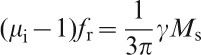
Interesting EM properties of nanosized particles of Co, CoxNi100−x,177 – 181 and Fez(CoxNi100−x)1−z,182 – 184 have been reported by Viau et al. The nanoparticles were synthesised by precipitation from metallic salts dissolved in polyols which acted as both solvents and reducing agents. In a typical synthesis of Fez(CoxNi100−x)1−z, for example, Cu(II) and Ni(II) acetate tetrahydrates and Fe(II) chloride tetrahydrate were dissolved with sodium hydroxide in 1,2-propanediol, with desired concentrations. The particle size was well controlled by using heterogeneous nucleation, which was realised by using a small amount of K2PtCl4 or AgNO3 dissolved in a mixture of 1,2-ethanediol and dihydroxydiethylether (1 vol.-%∶1 vol.-%). Magnetic metallic alloys of various composites could be readily synthesised with average sizes ranging from microns to submicrometre and to nanometre. Figure 28 shows representative TEM and SEM images of the metallic alloy nanoparticles,179,183 where the average sizes of the Co50Ni50,179 and Fe14Co43Ni43 particles are 6 and 120 nm respectively. It is worth mentioning that the powders reported were all quasi-spherical and non-agglomerated particles with very narrow size distribution.
Representative TEM and SEM images of nanosized magnetic alloys
To address the percolation problem when compacting the metallic alloy powders, they were coated by oxide layers with thickness of a few nanometres.182 For example, a layer of manganese oxide (MnO2) was produced to coat the metallic alloy particles by using potassium permanganate (KMnO4). This allowed to compact the alloy powders into high volume concentration composites without the occurrence of electric percolation. To further improve EM performances of the alloys, they were also thermally treated at high temperatures (120–350°C) in argon by using a rotating furnace.
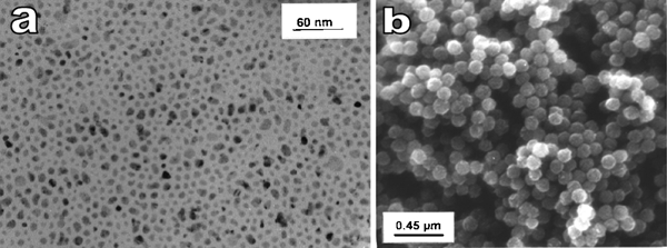
Microwave EM properties of the metallic alloy particles were demonstrated by their intrinsic permeability characteristics which were derived from measured data of composites with various volume concentrations. Figure 29 shows representative EM properties of the metallic alloy powders with different particle sizes. Two distinctive characteristics in EM responses of the materials were identified: the presence of multiple resonance as the particle size was decreased from microns to nanometres and shift of resonance to high frequencies with decreasing particle size. The multiple resonance behaviours of the nanosized particles had been attributed to the coexistence of non-uniform resonance modes that were resulted from the exchange energy contribution to the magnetisation precession within the particle.182,184 Since there was no permittivity data available, no attempt was made to evaluate microwave attenuation properties of the metallic alloy composites, which could be of great interest to the research community of EM materials. It is reasonably expected that such composites should be promising capability of microwave attenuation due to their broad and multiple resonance peaks.
Imaginary parts of intrinsic permeability versus frequency for Co80Ni20 of micrometre and nanometre sizes (left) and nanosized Fe14Co43Ni43 of different diameters (right): reproduced with permission from Ref. 183, copyright 1997, American Institute of Physics
Enhanced microwave attenuation was also observed in composites based on Ni nanofibres.185 Dong et al.185 developed a method to direct synthesise Ni fibres via the reduction of Ni2+ ions by using hydrazine hydrate. Composite made with the Ni fibres had higher dielectric loss tangent over the microwave frequency range than that made with Ni particles, while their magnetic loss tangents were almost the same. As expected, the composite with Ni fibres demonstrated better microwave attenuation behaviour.185 The high dielectric loss tangent of the Ni fibre composite was attributed to the space charge polarisations at the adjacent of contacting fibres and electron vibration along the fibre axle directions.
Zhou et al.186 reported a method to synthesise low density ordered mesoporous carbon silica nanocomposites with controllable content of Fe. The method was called solvent evaporation induced self-assembly. Fe nanocrystals were highly dispersed in the composites via in situ carbothermal reduction. One of the basic ideas for this approach was to reduce dielectric permittivity by introducing pores so as to maintaining a desired impedance matching. Porous materials would also have the advantage of low density. Depending on processing conditions, magnetic components in the C–SiO2–Fe nanocomposite powders were Fe or Fe3C. Composites with epoxy resin as matrix and 40 wt-%C–SiO2–Fe powders were fabricated and characterised. Promising EM performances of the composites were observed over 12–18 GHz frequency range.
Submicrometre α-Fe/SmO powders were prepared by a disproportionation reaction method from Sm2Fe17 in H2, followed by annealing in air.187 The powder was used to fabrication composite with epoxy resin at a ratio of 80 mass-%, which was 54 vol.-% (34 vol.-% α-Fe). This composite had microwave reflection loss RL less than −20 dB in the frequency range 0·73–1·3 GHz, while the composite derived from the unproportionated power exhibited almost no attenuation capability. The authors also claimed that the performance of the α-Fe/SmO composite was better than carbonyl iron.187
Fe–graphite oxide nanocomposite was reported by Zou et al. 188 The nanocomposites were prepared by inserting Fe3+ ions into the layers of graphite oxide, followed by reducing the Fe3+/graphite oxide compound at elevated temperatures in H2. Starting materials were equivalent amounts of Fe(NO3)3.9H2O and graphite oxide. The mixture was pyrolysed at 300°C and then reduced at high temperatures. The optimum reducing temperature was 600°C. Low temperature (300°C) was not sufficient to reduce Fe3+ into Fe, while high temperature led to the formation of Fe3C. Typical particle sizes of Fe were 10–100 nm. Electromagnetic properties were presented in the report, but no information was available on what types of materials were used for the measurement. In addition, microwave attenuation performance was not very promising, which could be attributed to the poor impedance matching of the materials if the Fe–graphite oxide nanopowders were directly used to make the samples for microwave characterisation.
Wei et al.189 synthesised Fe–SiO2 composite particle by H2 reducing a Fe2O3–SiO2 precursor prepared via a sol–gel process. The Fe2O3–SiO2 precursor was prepared to have a Fe/Si ratio of 13∶1, which corresponded to Fe content of 78·2 vol.-% in the final composite powders. Composites with 15 vol.-%Fe–SiO2 and paraffin were prepared and characterised. It was found that the powder treated at 800°C possessed optimum EM properties.
There are also reports on fabrication of FeCo–hexaferrite nanocomposite particles by reducing ferrite in H2.190,191 It was found that the FeCo metal nanoparticles precipitated coherently as thin flakes along the a–b planes of the lattice of the hexaferrites. BaCo2Fe16O27 and Ba2Co2Fe12O22 were used to fabricate nanocomposite particles. Although permeability of the nanocomposites was increased as compared to that of their original ferrites, their permittivity was promoted even more.190 In this respect, they are not ideal candidates for microwave attenuation applications due to their poor impedance matching.
Recently, Liu et al.198 synthesised Fe nanowires by using a CVD method. The Fe nanowires had a diameter of 70–200 nm and a length of 20–50 μm, synthesised through the decomposition of Fe(CO)5 at 523 K in Ar flow. Resin epoxy composites with 29 vol.-%Fe nanowires displayed much better dielectric and magnetic properties as compared to their flake-like and microwires counterparts. On the one hand, the nanowire composite had almost constant permittivity (ϵ′≈10 and ϵ″≈0·5) over the frequency range measured, while the composites with microwires and flake-like particles possessed much higher real and imaginary permittivity values. On the other hand, the nanowire composite showed high real and imaginary permeability values than the other two composites. This means that impedance value of the nanowire composite is closer to that of free space than the composites made of microwires and flake-like particles. As discussed earlier, reflection loss of a composite is determined by both impedance matching of the material with free space and the energy absorption capability of the material. Therefore, the nanowire composite had lower EM wave reflection loss than the microwire and flake-like particle ones.198
More recently, Sun et al. 199 synthesised a new type of nanosized Fe with hierarchical dendrite-like structures, which was made into composites with paraffin at 70 wt-% and a thickness of 2 mm that showed −10 dB reflectivity over 3–18 GHz. The nanostructured Fe powder was derived by reducing α-Fe2O3 that was synthesised by using a hydrothermal technique. The hierarchical nanostructure of the α-Fe2O3 was kept after the reducing reaction. Furthermore, by controlling the reduction temperature and flow rate of reducing agent (H2/Ar), Fe3O4 powder with the same hierarchical nanostructure was obtainable. The Fe3O4 could be transfered into nanosized γ-Fe2O3.
Other chemical methods, such as hydrogen thermal reduction,193 – 195 self-propagating combustion196 and thermal annealing, have also been reported.197 For example, Zhen et al. 193 used NiFe2O4 particles as starting materials to synthesise FeNi alloy nanoparticles by hydrogen thermal reducing at 400°C for 1 h. The obtained FeNi alloy particles had a diameter of ∼150 nm. Composite made with the FeNi nanoparticles of 15 vol% in wax had promising EM performances within the frequency range of 11–18 GHz. It is expected that EM properties of the composites can be further improved by increasing their volume concentrations. The method was also used to produce CoFe alloy nanoflakes from CoFe2O4 and CoFe/Al2O3 composite nanoparticles from CoFexAl2−xO4 particles for microwave composites.194,195 Specifically, the CoFe/Al2O3 composite nanoparticles were very good candidates for composite with impedance matching layer to achieve wide band microwave absorbers. A multilayer structured composite with impedance matching layer exhibited an ultra wideband at 10 dB reflection loss from ∼2·5 to 18 GHz.195
Direct current arc discharge
Lu et al. 200 synthesised core–shell nanoparticles of Fe and Ni from bulk metals by using a dc arc discharge method in a mixture of hydrogen and argon gases. In this case, tungsten was used as cathode and Fe and Ni metal bulks were used as anode. A trace of oxygen mixed with the inert gases was used to form a thin layer of oxides. Nanoparticles of Fe and Ni with well defined core–shell structures were produced, with shells of Fe3O4/γ-Fe2O3 and Ni2O3 respectively. Composites were made by mixing the nanoparticles with paraffin in a mass ratio of 1∶1. Their complex relative permeability and permittivity were characterised in microwave frequency range. Comparatively, the composite with Fe nanoparticles had higher dielectric loss tangent over the frequency range, which was attributed to the presence of a particular polarisation mechanism.201 Therefore, Fe nanoparticle composite possessed much better microwave attenuation capability than the Ni nanoparticle composite.
The group used the same method to synthesise Fe(C) nanoparticles.201 The particles had a very narrow size distribution of 20–40 nm. Composite with the nanosized powder (50 wt-%) and paraffin wax possessed an average dielectric loss tangent of ∼0·3 and magnetic loss tangent of ∼0·1, which therefore exhibited a promising microwave attenuation performance.
A ZnO coated Fe nanoparticle was reported to be synthesised from Fe97Zn3 alloy by using arc discharge process.202 The particles had Fe cores of 10–25 nm protected by a thin ZnO layer of 2–3 nm. Composite with 40 wt-%Fe–ZnO nanosized powder was fabricated and characterised. Promising microwave attenuation was observed in the composite over 2–18 GHz, which was attributed to the good impedance matching characteristic of the composite, owing to the protective ZnO shell and the particular core–shell microstructure of the nanopowder.202
Another example is Al2O3 coated FeCo nanocapsules derived from an alloy of (Fe60Co40)95Al5.203 Depending on discharging time, powders with particle sizes of 60–100 nm or assembles of the nanoparticles with sizes of 1·5–2 μm were obtained. Electromagnetic properties of the composites with 40 wt-% Al2O3-FeCo were characterised. The authors also reported a three-dimensional coral-like aggregate that was self-assembled by nanocapsules with FeCo cores and amorphous Al2O3 shell. A single layer of the composite with 40 wt-% of the nanoparticles displayed a 10 dB attenuation over 8–18 GHz at a thickness of 3 mm. The good EM performance of the composite was attributed to the strong natural resonance of the magnetic component and the interfacial polarisation at the core/shell interface of the three-dimensional aggregates.
High energy ball milling
High energy ball milling or mechanical alloying is a powerful technique that can be used to synthesise nanosized powders of various materials. However, it is difficult to prepare nanosized of metallic magnets by simple mechanical grinding due to the repeated of fracturing and cold welding effect. Therefore, nanosized powders of Fe or its alloys can only be obtained with the presence of other components, such as carbon,205 – 207 simple oxides,208 – 211 ferrites212,213 and organic solvents214 (as discussed in the previous section), via high energy ball milling.
Liu et al. 205 – 207 comprehensively studied EM properties of composites consisting of epoxy resin and Fe based magnetic powders with amorphous carbon synthesised by using high energy ball milling. Fe based magnetic components studied included α-Fe, Fe3C, Fe2B and Fe1·4Co0·6B. Take α-Fe as an example, the mixture of α-Fe (3–10 μm) and 6 wt-% amorphous carbon powder was milled at rotation speed of 3·3 rev s−1 for 30 h in Ar.206 The milled powder showed a particle size distribution from 100 nm to 1 μm. Electric resistivity of the milled nanocomposite was ∼100 Ω m, which was much higher than that of pure α-Fe. The resistivity of the nanocomposite was attributed to its special microstructure in which conductive particles were separated by the amorphous carbon. This was beneficial to maintain low permittivity for composite. For example, real permittivity of the composite with 40 vol.-% milled α-Fe–carbon (ϵ′≈12·4) was lower than that of the composite with 13 vol.-% pure α-Fe (ϵ′≈15). The two composites had same content of α-Fe. With no significant difference in magnetic properties, the composite made from the milled power displayed much better EM performance than that derived from pure α-Fe. Similar results were observed in composites with the nanocomposite powders of other Fe based compositions.205,207
Besides amorphous carbon, Y2O3 has also been used to prepare Fe based nanocomposites.208 – 211 Nanocomposites of α-Fe, Fe3B and Fe1−xCox with Y2O3 have been reported. For different magnetic components, different starting ingots, such as Y2Fe17, Y2(Fe1−xCox)17 and Y5Fe77·5B17·5, were used. Powders from the ingots were refined by using a high energy ball milling, followed by heat treatment in H2 and then O2. Compositions of nanocomposites could be readily controlled by compositions of the ingots. The nanocomposites prepared in this way had average grain sizes of 10–30 nm. Composites made from the nanocomposite powders exhibited promising microwave absrobing properties.
The method was also extended to prepare Fe–ferrite nanocomposites. A nanocomposite powder of Fe–Ba3Co1·8Fe23·6Cr0·6O41 was synthesised by milling a mixture of Fe and Ba3Co1·8Fe23·6Cr0·6O41 powders, in hexane for 30 h. The milled powder had a particle size of 100–900 nm and grain size of 20–30 nm.212 It was found the composites based on the Fe– Ba3Co1·8Fe23·6Cr0·6O41 nanosised powder possessed better microwave attenuation property than those with Fe or Ba3Co1·8Fe23·6Cr0·6O41 powders only. The advanced performance of the Fe–Ba3Co1·8Fe23·6Cr0·6O41 composite was attributed to the refinement in grain size of Fe and formation of flake-like Fe nanoparticles, as a result of the high energy ball milling. In a similar study, Wang et al.213 used a high energy ball milling to prepare core–shell particles of Fe0·7Ni0·3 coated with Co2W ferrite. The authors found that composite with the Fe0·7Ni0·3–Co2W powder had a largely reduced permittivity while maintaining an almost unchanged permeability, as compared to that with Fe0·7Ni0·3. The most distinct advantage of using ferrites is that they are also magnetic. Therefore, ferrites have obvious advantages over amorphous carbon and Y2O3. In this respect, nanocomposites of metallic magnetic alloys and ferrites should be further explored.
Physically compacting
Microwave properties of nanocomposites with Fe and Co embedded in ZnO and Fe2O3 matrix were reported by Brosseau et al. 215,216 For comporison, Fe and Co with sizes of micrometres were also studied. Composites for this study were prepared by mixing and pressing the metal powder, oxide powder and epoxy resin. Volume fraction of Ni and Co was up to 0·60, while that of resin was 0·09–0·17. All samples had certain porosities depending on the nature of the starting powders. The most striking feature was that the composites consisting of nanosized Fe and Co powders displayed a prominent gyromagnetic resonance in the microwave frequency range.215 The resonance was not observed in the composites with micron sized Fe and Co powders. Although several peculiarities could be responsible for the presence of the resonance in the nanocomposites, a sound explanation is not available. Nonetheless, the resonant characteristics of the nanocomposites make them highly potential to be used as EM materials. However, this type of nanocomposites had relatively high dielectric permittivity due to the high dielectric constant of ZnO (ϵ = 38·2−0·3j).216 In practical applications, dielectric permittivity of a microwave composite should be close to its magnetic permeability for a good impedance matching. It is therefore suggested to use other matrix with low dielectric permittivity instead of ZnO.
Non-metallic magnetic nanosized powders
Compared to their metallic magnetic counterparts, non-metallic magnetic (ferrites) nanosized powders are much less reported. Representative examples of nanosized ferrites and ferrite based nanocomposites are discussed as follows.173,199,217 – 223
Nanosized ferrite powders, Mn0·7Zn0·3Fe2O4 and Ni0·7Zn0·3Fe2O4, were synthesised via a chemical coprecipitation method. The powders had average particles of 10–52 nm, depending on calcination temperature. Composite made of 60% Ni0·7Zn0·3Fe2O4 displayed microwave attenuation at −10 dB reflection loss over 9–12 GHz.218 Xiao et al. 219 synthesised a core–shell structured MnFe2O4– TiO2 nanocomposites. Nanosized MnFe2O4 powder was prepared by using a polymer pyrolysis method, which was then coated with TiO2 via a sol–gel process. Composites with 60 vol.-% of the nanocomposite powders were prepared and characterised. It was found that dielectric permittivity increased with increasing content of TiO2. This is readily understandable, because TiO2 has higher permittivity than MnFe2O4. However, a maximum permeability was observed in the sample derived from the nanocomposite with 20%TiO2, which was not explained in the report. In fact, it is not suggested to use TiO2 to make composite with ferrites, because it has a relatively high dielectric permittivity (∼80). The presence of TiO2 will make it more difficult to reduce the permittivity of a composite for impedance matching.
More recently, Stojak et al.221 prepared polymer nanocomposites with 10 nm CoFe2O4 and Rogers polymer. The nanosized CoFe2O4 particles are synthesised via a chemical processing method. Composites with the CoFe2O4 nanoparticles up to 80 wt-% dispersed in Rogers polymer in hexane. Different from those composites prepared by mechanically mixing powders and epoxy resin, the nanocomposites reported by Stojak et al. 221 had very uniform distribution of the CoFe2O4 nanoparticles. A two-port microstrip linear resonator was used to characterise microwave responses of the nanocomposites. It was found that microwave response properties of the nanocomposites could be tuned by applying external dc field.
There are increasing number of reports on EM properties of composites based on nanosized magnetite (Fe3O4) powders.199,222,223 For example, as stated earlier, Sun et al. 199 prepared hierarchical nanosized dendrite-like Fe3O4 powders from α-Fe 2 O 3 of same structures. Wang et al. 223 synthesised monodispersed hollow Fe3O4 spheres with diameter of ∼500 nm and shell thickness of ∼150 nm by using a solvothermal process. Both types of Fe3O4 powders were of promising EM properties in the form of composites.199,223
Nanosized carbon materials
In recent years, nanosized carbon materials have drawn more and more attention as fillers to fabricate composite materials for EM applications. Carbon nanotubes are the most overwhelming nanosized carbon materials for microwave composite applications. Composites based on CNTs can be used for electromagnetic interference (EMI) shielding224 – 227 and microwave attenuation.228 – 242,244 Besides, there have also reports on other forms of nanosized carbon materials, such as graphite nanosheets245 and carbon nanocoils,246,247 for microwave applications.
Yang et al. 224 reported a multiwalled CNT–polystyrene foam composite showing advanced EMI shielding capability. The polymer foam composite containing 7 wt-%CNT had a shielding effectiveness of 20 dB. The primary EMI shielding mechanism was ascribed to the reflection of EM wave due to the high conductivity of the composites. The authors also found that, with a small amount of CNTs, EMI shielding effectiveness of the composites of polystyrene and low cost carbon nanofibres could be greatly improved.225 Similar EMI shielding effects were observed in composites of multiwalled CNTs with poly(methylmethacrylate)226 and single walled CNTs with epoxy resin.227
Microwave attenuation properties can be largely enhanced in composites by using CNTs filled or coated with magnetic components (such as Fe, Ni, FeCo, FeNi and FeCoNi) as active fillers.235 – 238,240 This is simply because magnetic contribution to EM performances was brought in. Carbon nanotubes filled or incorporated with other components (such as Er2O3, CoFe2O4, barium ferrite, Ni17S18 and Fe7S8) were also found to be useful in fabricate microwave composites.241 – 244
The EMI shielding and microwave attenuating characteristics of the composites based on nanosized carbon materials are mainly attributed to their high conductivity and dielectric losses. Composites with nanosized carbon materials alone are not expected to show EM performances comparable with those of magnetic alloys and magnetic ferrites. Hybrid nanomaterials by combining nanosized carbon materials with magnetic components could be an effective way to develop high performance microwave composites. In this respect, graphene or graphene oxide will be advantageous over CNTs or other forms of carbon, because their sheet structures are easier to incorporate with other materials.
Other nanomaterials
Besides those discussed above, there are also reports on EM properties of other nanosized materials, including ZnO,248 – 251 MnO2,252 and SiC.253,254 These non-magnetic materials can be used to fabricate composites that exhibited EM wave attenuation properties due to the dielectric lossy characteristics.
Zhou et al. 249 reported attractive microwave attenuation properties of composites with tetra-needle-like ZnO whisker (T-ZnO) as inclusions. The T-ZnO whiskers were made by using a simple thermal treatment of Zn at 500–800°C for 15–20 min in air. Images (SEM) of a T-ZnO whisker is shown in Fig. 30,249 together with an image of one-dimensional ZnO whiskers as a comparison. Length and basal diameter of the T-ZnO whiskers were 15–200 μm and 1·8–6·6 μm respectively. Composites were made with polyurethane as matrix and the T-ZnO whiskers as fillers. The composites were sprayed onto Al plates with thickness of 1–1·2 mm for measurement. Microwave attenuation performances of the composites were related to the aspect ratio, with optimum aspect ratio to be 19·7–28·6. Figure 31 shows reflection losses of the composites with different types of ZnO at a concentration of 50 wt-%.249 Obviously, the composite with T-ZnO whiskers had best wave attenuation behaviour, which possessed −10 dB reflectivity over 9 GHz up to 18 GHz. The observation was explained by considering multiple interfacial electric polarisation due to the special microstructures of the T-ZnO whiskers, disorder quasi-antenna structure form by radom distribution of the T-ZnO whiskers and piezoelectric character of ZnO. Microwave attenuation properties reported in other studies of ZnO were significantly lower.248,250,251 ZnO reserves to be further studied for EM applications due to its tremendously available morphologies.
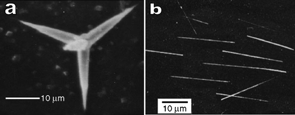
Images (SEM) of a T-ZnO and b one-dimensional ZnO whiskers: reproduced with permission from Ref. 249, copyright 2006, Elsevier
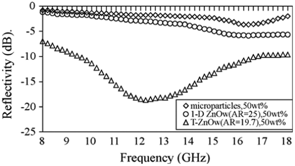
Reflection loss curves of ZnO–polyurethane composites with different types of ZnO: reproduced with permission from Ref. 249, copyright 2006, Elsevier
Microwave properties of composites with long conductive fibrous inclusions
It is well know that composites, made with conductive fibres of certain lengths, dispersed randomly or regularly inside polymer matrix, may respond resonantly to incident EM waves of certain frequencies. Such composites could provide high values of both real and imaginary parts of permittivity, even at extremely low volume concentrations of the fibre inclusions (e.g. <1 vol.-%),255 – 257 which makes them ideal candidates of light weight wave absorbers258 and frequency selective or shielding materials.256,257,259 Owing to the frequency dispersion characteristics of the composites, their dielectric constants can be negative over a certain frequency range, which is of great interest to the development of double negative materials.260 This is the main motivation to investigate such kind of composites instead of those with fibrous inclusions of much smaller sizes.
Effective permittivity of the composites with tiny conductive fibres (L

Generally speaking, any kind of conductive fibreous inclusions, of high conductivity, high aspect ratio and small thickness, could be employed as fillers of such composites. Practically, thin copper fibres,255,256 carbon fibres with diameters of about a few micrometres,258 copper coated polymer fibres259,263 and aluminium coated carbon fibres264 have been widely used to fabricate composites with significant EM properties during the last decade. The metal coated polymer fibres may have similar bulk conductivities and percolation ratios as compared with metallic fibres but have much lower densities. However, the coating thickness of a metal coated polymer fibre should not be less than micrometres, which is close to the skin depth of incident EM wave at microwave frequencies. Different type of resonance phenomena could be found in the composites with conductive fibres having a thickness that is less than the skin depth of a incident wave, which will not be discussed in detail here. Therefore, composites with metallic nanofibres, carbon nanofibres and nanotubes as fillers are not touched in this review. The main difference lies on that most conductive nanofibres do not show any resonance peak at microwave frequencies. Glass coated amorphous ferromagnetic microwires fabricated with casting (Taylor–Ulitovsky) method could also be used to make fibre composites.260,267 As compared with metallic fibres, glass coated fibres have better chemical resistant. Also, microwire composites have very low (or no) dc conductivity due to the isolation of the glass coating, which may be of interest for some applications. For example, magnetically tunable resonance behaviour of microwire composites has been reported, which may find applications as smart sensors or actuators.265
Effective medium approximation
Although percolation effect of conductive fibre composites was studied by using Monte Carlo method in 1980s,266 high frequency EM properties of composites containing very elongated conductive fibres in a dielectric matrix had not been investigated comprehensively until 1996.267 It was found that the percolation threshold p
c, was inversely proportional to the fibre aspect ratio p
c≈ba, where b is radius of the fibre and 2a is its length. Figure 32 shows a representative pattern with randomly distributed fibres. It is a two-dimensional composite sheet containing randomly distributed long fibres generated by an Monte Carlo algorithm,266 where a conducting fibre may intersect on average with N other fibres. When N is small, the fibres are separated from one another and the probability to percolate through the conducting fibres is equal to zero. When N is large enough, carpet is formed as shown in Fig. 32 and the probability to percolate is equal to one. An important finding from Refs. 264 and 267 is that, when 
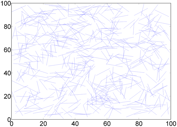
Computer generated two-dimensional randomly distributed long conductive fibres
Effective medium theory is a conventional approach to simulate the properties of composites. Effective medium theory has the virtue of relatively mathematical and conceptual simplicity as well. Its predictions for ordinary metal dielectric composites are usually sensible physically and offer quick insight into problems that are difficult to be addressed by other methods. The standard formulation of EMT includes the self-consistent equation for the effective permittivity of composites ϵ e, which is usually referred to as the permittivity of effective medium. This equation is derived on an assumption that the polarisabilities of both the conductive and the dielectric grains, embedded into the effective medium, add up to produce zero.
The effective properties of the composites with spherical inclusions of electrically small size have been solved with classic mixing law, which have been validated by experimental results.261 There are two mean field approximations widely used in the literatures: Bruggeman effective medium theory (equation (17)) and symmetrical Maxwell–Garnett approximation (equation (18))261
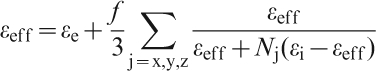
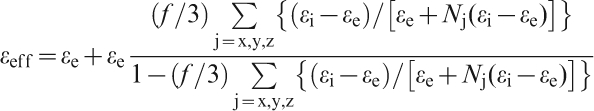
These two theories were developed to describe the properties of the composites containing spherical conductive grains. However, when they are extended to non-spherical inclusions, certain disagreement could be found in predicting the percolation ratio of the composites.265 Hence, an effective medium theory for conductive fibre composites was proposed.265 This theory readily addressed the discrepancy problem by assuming that the conducting fibres are surrounded in the composite by the medium with scale dependent conductivity.
To compute the effective permittivity of a composite, ϵ = ϵ′−iϵ″, the averaged polarisability of the inclusions is assumed to be the polarisability of a homogeneous medium with permittivity ϵ
eff. To obtain accurate results, the fibre conductivity must be renormalised to account for its inductance. For the composites with low volume concentration of fibres p, interaction phenomena can be neglected and the well known dilute limit approximation as given in the Lorentzian dispersion law for the permittivity as a function of frequency f, is given by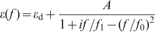
For microwave applications involving millimetric fibres, planar distribution of the fibres is most appropriate, since the resulting composites are typically thin layers. In this case, the parameters of the dispersion law in equation (19) are derived from the dilute limit approximation as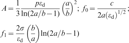
Composites with high volume fibre concentrations are of interest, since they are expected to exhibit relatively high microwave permittivity. For composites with periodically distributed fibres, the common approach is to employ numerical techniques suitable for dipole arrays. The numerical results are typically frequency dependent reflectance or transmittance, instead of permittivity. The description in terms of permittivity is used only within quasi-static approach that does not account for the resonance. It is shown that the permittivity is influenced greatly by the ohmic contacts among individual inclusions. Owing to the interaction among the inclusions, the dependence of A on p is non-linear at higher values of p, though no approximation for this dependence is available. Therefore, not much has been known about effective microwave permittivity of the composites with periodically distributed inclusions. It is only established that the Lorentzian dispersion curve is not distorted and the resonance frequency, which is the same as the resonance of reflectivity or transmittance, is dependent significantly on either the spacing between every two neighbouring fibres or the volume concentration of the fibres in the composites.
Numerical methods and models
Besides the EMT approach, an alternative solution is to consider the real geometry of the fibres via numerical methods instead of treating them as dipoles. For composites with periodically distributed fibres, numerical techniques are well established. Typically, a composite is divided into small cells (or elements) and the fields are solved in a finite number of points using basis function under certain boundary conditions. Normally, for a specific problem, the smaller the cell size, the more accurate the results are obtained. However, numerical methods are either limited by memory capacity of the computers used or required long computational times. The most useful numerical methods in EM computations of composite materials include the finite element method (FEM),268 – 270 the finite different time domain (FDTD) technique,271,272 the method of moments (MOM)273 and hybrid methods (FEM boundary integration, FEM/FDTD hybrid and FEM/MOM hybrid methods, etc.).
The MOM was once used to obtain microwave properties of planar composites with randomly distributed long conductive fibres (but without host matrix).273 In this case, a random periodic model was used to represent the arbitrary fibres that were considered as filaments and distributed in a two-dimensional plane. Its reflectivity and square impedance were calculated and averaged over 50 Monte Carlo steps. The simulated results, amplitudes of reflection coefficient, were in a good agreement with the experimental data measured by using a free space measurement method. A shift in resonance frequency was observed, which was attributed to the effect of the host matrix. However, the numerical inaccuracy of the MOM modeling could be attributed to the fact that the use of filaments to represent the real fibres might not be appropriate, as discussed later. Filament approximation is only valid when the wire radius is significantly smaller than both the wavelength and the wire length. As a result, these approximations are also invalid when spacing of the fibres is too small (less than several times of radii of the fibres).256 As shown in Fig. 33, the pattern of random distribution in Fig. 32 can be represented by the random periodic pattern used for the numerical modeling. Therefore, the calculation only needs to be carried out in a finite range instead of an infinite area. When the periodicity is larger than a few times of the length of the fibres, MOM results converge to that predicted by the EMT calculation. It means that the calculation range is big enough to represent the real structure.
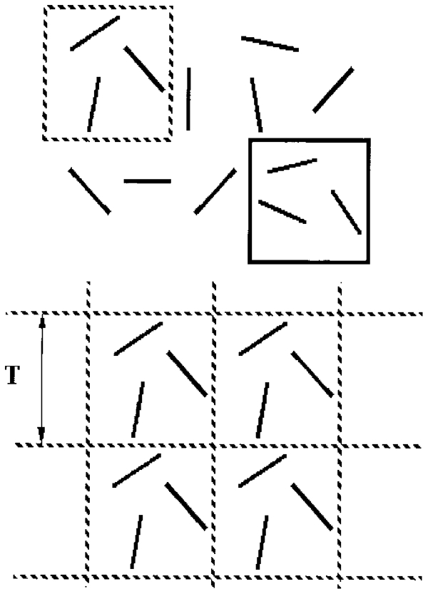
Random periodic pattern for numerical calculations
The FDTD technique is able to solve two-dimensional composites of small spherical inclusions (as compared with wavelength).272 It was found that numerical results are within the theoretical bounds obtained from EMT. Also, Bruggeman model appears to be closest to the numerical calculation which is believed to be the exact solution.
The FEM is a very useful technique in engineering and science due to its flexibility in handling both complex geometry and anisotropic material properties. In contrast to the FDTD technique, the FEM requires less elements (unknowns) to model thin fibres, resulting in lower computing resources requirement and reduced computational time. The FEM is also more suitable than the MOM for composites with fibres of realistic geometry and anisotropic host matrix.
A commercial FEM software, high frequency structure simulator (HFSS) developed by ANSOFT, has often been employed to study fibre composites.255 – 257 Tetrahedral elements were used to model the composite sheet, the perfectly match layers (PMLs) and air layers in between. Typically, the object (composite sheet) resides in an unbounded free space. However, the FEM requires meshing of the free space region as well, which cannot be done on computer if it is of infinite extent. Hence, the PML, a fictitious anisotropic layer, is applied to truncate the unbounded space to a finite size, while emulating a unbounded free space environment. The region between the PML and the composite sheet is air, with a thickness larger than a quarter wavelength of the incident wave. Adaptive meshing technique was adopted to automatically refine the mesh where the computational error is large. A convergence condition was defined (for example, the change in electric field strength between the present and the previous iterations is less than a prescribed value) and upon satisfying this condition, the computation will be terminated automatically.
For composites with randomly distributed fibres, a unit cell (with size of d) comprising some randomly distributed fibres is used to model the composite sheet to be fabricated and measured, with the same volume concentration. If the cell size d is small, the reflection coefficient of the composite sheet will depend on d. However, for d>d c, where d c is the minimum homogenisation size, the reflection coefficient is independent of d. The minimum homogenisation size has been investigated by Nguyen and Maze–Merceur.273 In that study, the periodicity used was 40 mm, larger than d c. The influence of perodicity on the results has been checked by calculations on unit cells of various sizes of the unit cell up to 60 mm, with good agreement obtained.
The randomly distributed fibres are generated using the Monte Carlo method. The basic procedure is to generate the random location and the orientation of fibre randomly distributed within the two-dimensional central plane of the sheet. Thereafter, it is tested for overlapping of the fibres. If no overlapping is found, the fibre location and orientation are used on the in-plane surface. If overlapping occurs, new location and orientation will be generated. The procedure is repeated until the desired number of fibres is reached. This approach emulates the practical distribution of fibres within composite slab very well for volume concentration below the percolation threshold, since the host matrix or oxide layers on the surface of the metallic fibres prevent current from flowing across the fibres.
Figure 34 shows a schematic diagram of the numerical model. A TEM wave with electric field E, parallel to the layer and wave vector k, perpendicular to the layer surface illuminates the model for normal incidence. The PML boundary conditions are imposed on the surfaces that are perpendicular to the wave vector. Owing to the periodicity in geometry, a linear phase relationship exists between the fields on the surface of the walls of the unit cell. The surface with free variables is commonly known as the master boundary, while that with constrained variables is known as the slave boundary. The tangential electric field components at the slave boundaries are expressed in terms of the tangential electric field components at the master boundaries, with the phase between the master and slave boundaries calculated from the incident angle and the periodic cell size. The periodic or linked boundary conditions are applied to the surface parallel to the wave vector. To model composites with periodically distributed fibres, a similar numerical approach is used, with a single fibre parallel to the electric field in each unit cell. Coherent transmission of the composite sheet can be obtained from the ratio of the average intensity of transmitted electric field to that of the incident field according to equation (21). Phase of the transmission coefficient can be calculated from the average phase of the total field and the incident field on the surface S
out, as shown in Fig. 34. From the computed complex transmission coefficients T, complex effective permittivity ϵ
ff can be obtained, with an assumption that the layer is non-magnetic, by solving the equation
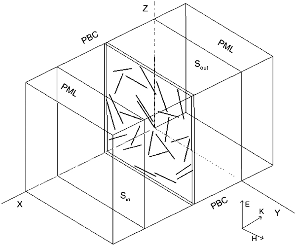
Schematic diagram of numerical model of planar composites with conductive fibres: reproduced with permission from Ref. 256, copyright 2005, American Institute of Physics
NEC2 program developed by Lawrence Livermore Laboratory was used as a comparison. It employs the MOM algorithm and the electric field integral equation, which is well suited for thin wire structures. This thin wire approximation assumes that transverse current and circumferential variation of current can be neglected with respect to the axial currents on the wire. Therefore, the surface current can be represented by a filament on the wire axis. The Radar cross section of a single fibre is computed using NEC2 to obtain the resonance peak. Resonance frequencies of the composites with periodically distributed copper fibres of different diameters are calculated with FEM and MOM methods, before compared with the measurement results shown in Fig. 35. The resonance frequency calculated with the FEM is closer to the measured results, as compared with the MOM.
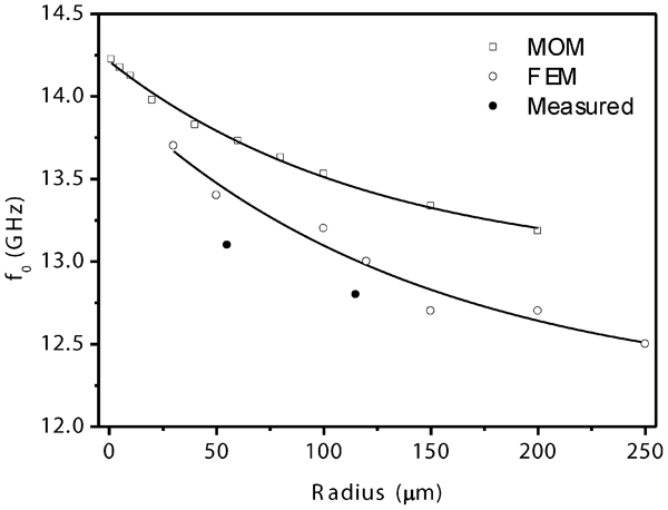
Resonance frequency of fibre composites obtained with numerical calculation and measurement: reproduced with permission from Ref. 256, copyright 2005, American Institute of Physics
Measurement methods
Transmission like coaxial line and waveguide lines, are usually used as sample holders for the measurement of effective permittivity of composites at microwave frequencies. The most widely used holders include APC-7 (7 mm) coaxial line and rectangular waveguide. Network analysers are generally adopted to provide the source signal and measure the S-parameters.274 However, the main limitation of the transmission line method lies in that size of the sample holders is less than or comparable with the wavelength at the measurement frequency. If the length of fibres is already comparable with the wavelength at the frequencies of interest, not enough number of fibres could be included in the sample. As a result, this transmission line method is not useful to composites with long fibres. This problem was addresed by Matitisne et al.275 by using a 15 cm slotted coaxial resonator. However, permittivity values of the samples measured had to be obtained from the shift of the resonance frequencies. In addition, the measurement could not be carried out continuously within a frequency band of interest.
Free space methods are non-destructive and contactless. Hence, they are especially suitable for measurement of complex electric permittivity and magnetic permeability of the composites, with large inclusions, under high temperature conditions, or at bias electric/magnetic fields. Free space system with capability to measure complex permittivity and permeability of magnetic materials from 8·6 to 13·4 GHz was first proposed by Ghodgaonkar et al. in 1990.276 Two port TRL (thru, reflect and line) calibration technique used could eliminate errors due to the multiple reflections and increase accuracy of the measurement. However, precision control of the movement of transmitter and receiver antenna is required for the measurement setup, which increases cost of the system. Recently, a new calibration method, gated reflect line calibration method, was introduced.277
Complex reflection and transmission coefficients of a planar sheet with size of larger than 20×20 cm were measured by using the free space measurement technique,256 as shown in Fig. 36. The experimental set-up includes a vector network analyser, with broadband transmit and receive EM horn antennas mounted vertically and operated over 2 to 18 GHz. To eliminate multiple scattering between the sample and the horns, time domain gating was applied. Diffraction effects at edges of the sample were minimised by using a piece of ring shaped high quality wave absorber with an inner diameter of ∼15 cm that was attached to the transmit horn. Effective permittivity of the composite was extracted from the measured transmission coefficient in the same manner as in the numerical calculation using equation (21). The total measurement error in permittivity was about 5–10% of the permittivity values of the samples under test, as revealed by the measurement of standard samples.
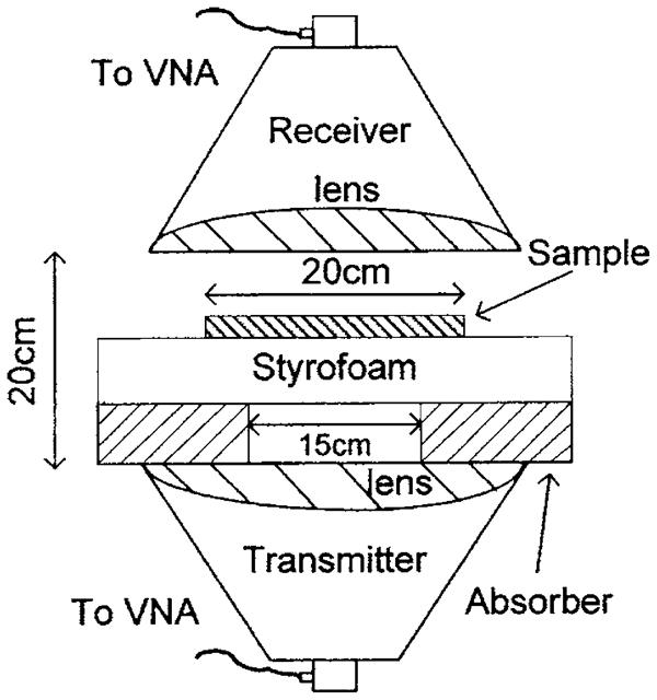
Free space transmission/reflection measurement system: reproduced with permission from Ref. 256, copyright 2005, American Institute of Physics
Interesting properties and phenomena of long fibre composites
Shift of resonance frequency of composites embedded with long conductive fibres
It has been shown that the shift in resonance of conductive fibres embedded in a sheet sample depends on the sample thickness.278 For thin samples, the resonance frequency drops rapidly with increasing thickness, but remains relatively unchanged beyond a certain thickness. For samples with thickness larger than this critical thickness, the resonance frequency is approximately the same as that of an infinite bulk material and depends only on material properties of the composites.
Resonance frequencies of the samples between thin and thick were reported in Ref. 255. The experimental results shown in Fig. 37 corresponded to host matrix with 15% mass concentration of aluminium powder. Thin sample presents the measured permittivity for a 0·2 mm thick sample, while the data of thick sample correspond to a 1 mm thick sample. As the thickness increases from zero to 0·2 mm, the resonance frequency shifts from 13·6 GHz to 6·7 GHz. When the thickness is further increased to 1 mm, the resonance frequency shifts to 4·3 GHz. Therefore, the samples should be as thick as possible. On the other hand, the samples under study should not be too thick, otherwise the measurement accuracy would degraded. In view of this, samples that are several times the critical thickness could be regarded as optimal. Unfortunately, no analytical expression for the critical thickness is available in the literature. For this reason, the thickness dependence of the resonance frequency was investigated by numerical simulation, using HFSS. The model consists of a 10×10×30 mm box filled with air. A composite layer with dimensions of t×10×30 mm is placed at centre of the box. The thickness t is varied from 0·1 to 1·5 mm. A copper fibre with length of 10 mm and thickness of 0·1 mm is located at centre of the layer. A plane wave illuminates the layer at normal incidence, with electric field parallel to the fibre. A radiation boundary condition is defined on surface of the air box. Resonance frequency of the fibre is derived from the calculated frequency response of RCS of the layer.
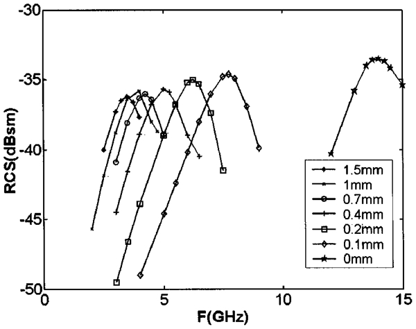
Calculated resonance frequency from RCS of thin fibre with length of 10 mm embedded in composite layers of various thickness: reproduced with permission from Ref. 255, copyright 2003, American Institute of Physics
Based on the numerical results, for all permittivity values used in that study, the samples with 1·5 mm thick sheets can be regarded as bulk materials in relation to the dipole resonance of a 10 mm long fibre.
Composites filled with carbonyl iron powder were also studied. These composites are isotropic. The size of the particles (5 μm) was small as compared to the thickness of the fibres (100 μm). Therefore, the composite with these iron particles was homogeneous as compared to that with the fibres. However, these composites possessed magnetic properties that must be taken into account in the analysis. This is because permeability affects the resonance frequency in the same way as permittivity. The resonance frequency is inversely proportional to the refractive index defined by n = (ϵ′μ′)1/2.
Another filler was aluminium powder. The maximum size of the particles was 15 μm. Therefore, these particles also formed a homogeneous host matrix. The data on the location of the resonance frequency for this case are shown in Fig. 38. The results obviously deviate from the 1/2 law that is expected of a non-magnetic, infinite, homogeneous, isotropic medium. Instead, the measured data vary gradually as a function of ϵ, and can be fitted by an exponential law with an index of ∼0·3. In Fig. 38, the exponential law is represented by a solid line that is normalised so that f 0 = 13·6 GHz for ϵ = 1.
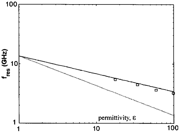
Measured resonance frequency plotted against refractive index for copper fibres embedded in composites filled with carbonyl iron of different concentrations: reproduced with permission from Ref. 255, copyright 2003, American Institute of Physics
Therefore, for a fibre embedded in a matrix containing aluminium power, the measured resonance frequency shift did not obey the ϵ 1/2 law. The aluminium samples were highly anisotropic, in contrast to the iron powder samples. Hence, it is necessary to consider the effect of the anisotropy in permittivity of the host matrix on resonance behaviours of the embedded copper fibres. In other words, the anisotropy of the composites filled with aluminium powder could be responsible for the anomaly observed in location of the fibre resonance frequency. The same is true concerning the composites filled with carbon fibres.
Effect of distribution of fibres on resonance and effective permittivity
It has been shown that Q-factors of composites with periodically distributed fibres are significantly higher than those of the composites with randomly distributed fibres. Comparatively, Q-factors of the former were also more sensitive to changes in resonance frequency. First, the inter-element spacing D
x, perpendicular to the fibre axis, had an effect on resonance frequency. Numerical (empty circles) and experimental (filled circles) results are shown in Fig. 39, where the inter-element spacing parallel to the fibre axis D
y is 20 mm. The resonance frequency f
0 can be related to the equivalent lumped circuit parameters as follows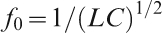
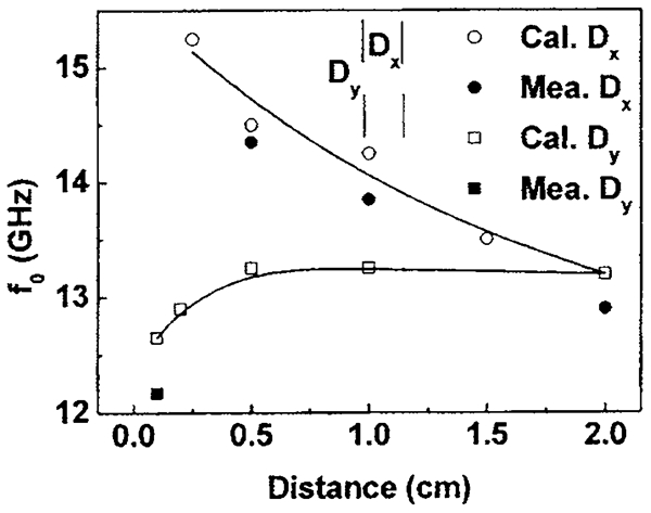
Dependence of resonance frequency on periodic of composite with periodically distributed fibres: reproduced with permission from Ref. 255, copyright 2003, American Institute of Physics
Figure 39 also shows the results for the case of varying D y, with D x being sufficiently large for negligible interactions between adjacent parallel fibres. In this case, the resonance shifts to lower frequency when D y is decreased. The downward shift in resonance frequency can also be explained by equation (22). The effective lumped capacitance is due mainly to the two ends of two collinear fibres (one above the other) that are closest to each other, as well as the entire lengths of both fibres from one end to the other. Since these two ends have opposite charges, a capacitance is built up and varies inversely with the end-to-end separation. As D y is decreased, the end-to-end separation is correspondingly reduced, leading to a higher capacitance which lowers the resonance frequency. However, the shift is only ∼0·35 GHz as the separation decreases from 20 to 0·2 mm.
Cluster effect inside fibre composites with high concentrations
Figure 40 shows transmission coefficients of the composites with 0·5% randomly distributed fibres with and without overlapping.257 Solid lines are measured results of the fibre composite without overlapping of fibres. A single resonance peak can be observed. For the sample with clusters of overlapping fibres, the resonance amplitudes are smaller and the resonance peaks spread over a wider frequency range as compared to the case without overlapping. Differences in the frequency spread of resonances and resonance amplitude between samples with and without cluster at other concentrations and fibre lengths were also observed. It is found that cluster effect can reduce the amplitude and broaden the bandwidth of the resonance peak.
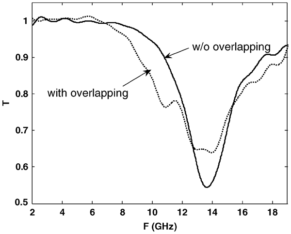
Transmission coefficients of composites with randomly distributed fibres with and without overlapping of fibres: reproduced with permission from Ref. 257, copyright 2007, Institute of Physics
The bandwidth of EM response is extremely important for various applications, such as frequency selective surface. However, it is difficult to determine the contribution of each fibre cluster, because it is always a collection of different clusters with different orientations in a sample. To fully understand the response of clusters to incident EM wave with different polarisations, it is necessary to consider an array with a fibre cluster within each unit cell. The simplest case is to have two overlapping fibres in each cell. This simplified approach is sufficient to demonstrate the basic response of a single cluster for the case where the interaction between clusters is much smaller than that between fibres within the cluster. The assumption is valid because similar response can be found in array with the same cluster but different periodicity.
Figure 41 shows measured (line) and calculated (symbols) transmission coefficients of a cluster with two fibres. The difference between the measured and the calculated resonance peaks (frequency and amplitude) is attributed to insufficient accuracy of the geometrical parameters in the implemented sample or the simplification of the numerical modeling. For E field along 0° (horizontal polarisation), only one resonance (at ∼13 GHz) is observed. The resonance frequency is close to that of a single fibre. For E field along 90° (vertical polarisation), one more resonance (at 9·5 GHz) is observed. The resonance frequency is corresponding to the effective length of the fibre cluster (∼15·6 mm). For E field along the 45° direction (parallel to the axial direction of one fibre), both resonances (at 9·5 and 13 GHz) of similar amplitude are noted. Owing to the limited frequency range (2–20 GHz) of the free space system, transmission coefficient at higher frequency is not available. Most probably, one more resonance peak would appear at higher frequency (>30 GHz) owing to the symmetry of the fibre cluster. However, the peak is quite far away from the first resonance peak and therefore is of no significant interest for real applications.
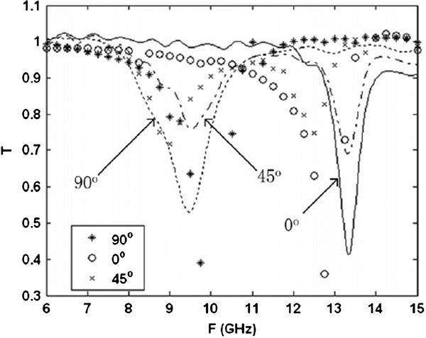
Transmission coefficients of two fibre cluster array at different polarisation angles: reproduced with permission from Ref. 257, copyright 2007, Institute of Physics
When the two overlapping fibres were isolated by a dielectric adhesive tape, similar resonance behaviour was also observed in the measurement, only with a slight upward shift in resonance frequency of the clusters. This means that cluster effect is due to the interaction between the two overlapping fibres and is not due only to physical or electrical contact. When the fibre cluster is replaced by a bended fibre of identical shape and length (15·6 mm), multiple resonances were not observed, regardless of the polarisation of the incident electric field. Therefore, when modeling randomly distributed fibres, long fibres cannot be simply used as substitutes for overlapping short fibres, as the interactions involved in the two configurations are different. Single fibre may have resonance even if it is close to or is in physical contact with other fibres. This explains why the observed resonance is close to the single fibre resonance frequency in a composite with randomly distributed fibres.
Cluster formed by overlapping fibres has multiple resonance frequencies, which is related to the lengths of the cluster or that of single fibre. Interactions between fibres within a cluster are not eliminated by electrical isolation. Cluster effect well explains the observations that the broadening of the resonance peak in composites with randomly distributed fibres and that the resonance frequency remains close to that of a single fibre. The Lorentzian formula with curve fitting parameters provides adequate description on the EM properties of the composites with fibres at various length and concentrations.257
Metamaterials and structures with advanced EM properties
Electromagnetic properties of materials with simultaneously negative permittivity and permeability, or left handed materials, were first discussed by the Russian physicist Veselago in 1968.279 He theoretically investigated EM consequences of a left handed material and predicted that such a medium would have dramatically different propagation characteristics stemming from the sign change of the group velocity, including reversal of the Doppler shift and Cherenkov radiation, anomalous refraction, and even reversal of radiation pressure to radiation tension. However, these effects could not be experimentally verified at that time simply because materials with negative refractive index were not available. The experimentally verified negative index at microwave frequencies by Shelby et al. 280 with a structured metamateial in 2001 inspired an explosive interest of the research community. The metamaterial consisted of a two-dimensional array of repeated unit cells of copper strips and split ring resonators on interlocking strips of standard circuit board material.
Metamaterials offered an entirely new route to further enhance the capability of people to design material properties at will. Different from the normal materials, physical properties of metamaterials are not primarily determined by intrinsic properties of the chemical constituents, but rather by the specific structures of metamaterials. These artificial structures function as atoms and molecules in traditional materials; while through regulated interactions with EM waves, they can produce fascinating physical properties which are unavailable in naturally occurring or chemically synthesised materials. This is the reason why these composite structures are termed as metamaterials, which literally stand for materials beyond natural ones.281 – 283 Various exotic physical phenomena, such as subwavelenth image resolution284,285 and cloaking effects,286 – 288 have been created by using metamaterials, which may find various potential applications, such as antenna radoms, bandpass filters, microwave couplers and high resolution optical lithography.
On the one hand, many of the intrinsic properties of metamaterials, e.g. lossy, anisotropic, and frequency dispersive, etc., pose limits for many of the applications. On the other hand, if those properties can be utilised properly, better or even new devices and applications may be realised. This section will introduce metamaterials for some practical applications in the microwave range. The first part of this section covers metamaterials used as microwave absorbers. After an overview on the progress that has been reported in the open literature by other researchers, focus will be on the works conducted in the authors lab, regarding the design and optimisation of performances of metamaterial microwave absorbers, by taking into account dielectric and magnetic properties of the substrates. Second part is regarding the design and evaluation of performances of smart metamaterials or structures with tunable EM responses. Lastly, a new type of metamaterials based on ferrite cores and metal coils with interesting EM properties with be introduced. Systematic theoretical study will be presented and possible applications of such new metamaterials will be highlighted.
Metamaterial microwave absorbers
In most cases, efforts were made to reduce the electric and magnetic losses of metamaterials, so as for practical applications requiring low loss tangents. For example, it has been shown that a small value of loss could significantly reduce the effectiveness of evanescent wave enhancement which is responsible for the super lens and enhanced tunneling effects.289 – 291 However, metamaterials with high losses can be used to absorb EM waves.
Metamaterials are constructed based on resonant units. The resonant units of metamaterials according to the conducting patterns used, e.g. split ring resonators (SRR), short strip pairs (SSPs) and electric ring resonators, can be simplified into equivalent LC circuits.292 – 294 Usually, if the materials used in the design are not magnetic, i.e., do not have high permeability, L is not very large, since it is determined by the area of the current loop and the permeability of materials inside the loop. However, C, which is the direct determinant of resonant frequency, can be easily tailored over a wide range. The size of a resonant unit can be much smaller than the wavelength at the resonant frequency. In this sense, metamaterials are good candidates for fabrication of thin absorbers.
In this subsection, an overview is given to microwave metamaterial absorbers which are comprised of subwavelength resonant units. Since the operation frequency of a metamaterial absorber is controlled by the scaling of the constituting unit cells,295 the techniques developed at the microwave frequencies are also applicable to higher frequency devices, and vice versa. Therefore, representative works of terahertz, infrared and even higher frequencies are also included.
Metamaterial absorbers reported in the open literature can be classified into two groups, depending on whether a conducting ground plane is used or not. Therefore, metamaterial microwave absorbers with and without conducting ground planes will be reviewed in general, and thereafter, particular attention will be paid to the ultra thin absorbers developed in the authors lab.
Metamaterial absorbers without conducting ground planes
In 2006, Bilotti et al. 296 proposed an electrically thin (λ/20) SRR based absorber without conducting ground planes. The absorber was comprised of a certain number of parallel columns of SRRs and a conventional resistive sheet, whose resistance was equal to the free space characteristic impedance. When the SRRs were excited by the magnetic fields of the incident waves, at the resonant frequency, the magnetic fields were very high in the centre of the SRRs, while the electric fields had maximum around the stems of the SRRs. The resistive sheet located near the resonating SRRs absorbed the EM energy of the incoming waves. Experimental verification of the design concept can be found in Ref. 295. As mentioned in Refs. 295 and 297, metamaterial absorbers without conducting ground planes are useful to reduce reflectivity from non-metallic objects at desired frequencies, without increasing the response at other frequencies.
In 2008, Landy et al. 298 and Tao et al. 299 reported a design of polarisation dependent one-dimensional absorbing metamaterial with near unity absorbance at a single frequency. Electric coupling was supplied by an electric resonator. Magnetic coupling was created by combining the centre wire of the electric resonator with a cut wire in a parallel plane separated by a substrate. Both the electric and the magnetic couplings could be tuned rather independently. Therefore, ϵand μ were decoupled. Each resonance could be tuned individually. By manipulating the lossy ϵ and μ of the metamaterial to match each other at certain frequency, zero reflection of incident EM waves was realised, since the wave impedance of the metamaterial was equal to the free space value at that frequency. Perfect absorption was then achievable by the lossy metamaterial with enough thickness. Based on similar principle, Wang et al. designed a polarisation dependent wide angle three-dimensional metamaterial absorber.300 The polarisation dependent design can be further modified to be polarisation independent, as reported in Refs. 301 and 302.
Besides planar configurations, metamaterial absorbers with other physical shapes have also been widely reported. In Ref. 303, Ng et al. theoretically demonstrated a metamaterial frequency selective superabsorber which consisted of an absorbing core material coated with a shell of isotropic double negative metamaterials. Theoretically, for a fixed volume, the absorption cross-section of an absorber can be made arbitrarily large at one frequency. In Ref. 304, loss manipulation in EM cloaks for perfect EM wave absorption was discussed. Based on the theoretical work in Ref. 305, Cheng et al. 306 experimentally demonstrated an omnidirectional metamaterial absorber at microwave frequencies in 2010, which could trap and absorb EM waves coming from all directions spirally inwards without any reflections due to the local control of EM fields.
Metamaterial absorbers with conducting ground planes
Metamaterial absorbers with conducting ground planes can be effectively used to reduce reflectivity from metallic planes just as effectively as the conventional absorbers based on composites with various magnetic or non-magnetic inclusions, as discussed above. These metamaterial absorbers are generally constructed by placing a resistive or highly conductive flat surface with either periodic or non-periodic patterns on top of a grounded dielectric or magnetic substrate (see e.g. Refs. 307–319). In this respect, the strong coupling between the pattern and the conducting ground plane differentiates this kind of metamaterial absorbers from the conventional absorbers with similar configuration but thicker substrates. For a thin substrate, the patterns and their images with respect to the conducting ground plane effectively construct resonant units functioning like SSPs. The top patterned surface, together with the whole structure sometimes, are also called metamaterial surface, frequency selective surface, high impedance surface or artificial magnetic conducting surface, etc., by different researchers. The top surface can be multilayered structures, which are not covered here.
According to the transmission line theory, surface impedance at top surface of the metamaterial absorbers can be expressed as307,320
–
323
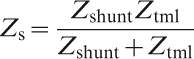
For lossless substrate and highly conductive flat surface, Z s is very high at around the resonant frequency. A resistive sheet with proper impedance can then be placed on top of the conductive flat surface to reduce reflectivity.307,325,326 This idea resembles that of Salisbury screens.327 – 329 However, the resistive sheet has to be placed at a λ/4 distance away from the conducting ground plane of Salisbury screens. The capacitive Z shunt can be tailored in a large range by changing not only permittivity of the substrate but the periodic pattern. Therefore, very low resonant frequency can be achieved even for electrically ultra thin substrates by using metamaterial absorbers.
The resistive sheet and the highly conductive flat surface can be replaced by a resistive flat surface with proper periodic patterns.308,330 – 333 Furthermore, the patterned resistive sheet can be replaced by alternatively soldering lumped resistors between highly conductive periodic patterns.334 – 340 This configuration is similar to that of the circuit analogue (CA) absorbers.329,341 Therefore, some researchers also called it circuit analogue absorber. However, for normal CA absorbers, the distance between the conducting ground plane and the CA sheet is approximately λ/4, while the equivalent RLC series circuit of the CA sheet resonates at the centre frequency f 0.329 In other words, normal CA absorbers are similar to the Salisbury screens, whereas the metamaterial CA absorbers have reactive components, due to the periodic patterns of the resistive sheet. Below (above) f 0, reactive components of the CA sheet are capacitive (inductive), cancelling the inductive (capacitive) components of Z tml. The cancelling effect leads to an increase in the absorption bandwidth. Owing to the large distance between the CA sheet and the conducting ground plane, the equivalent RLC series circuit of the CA sheet can even be obtained without considering the influence of the conducting ground plane. For metamaterial absorbers, thickness of the substrates is usually much less than λ/4. Strong coupling exists between the periodic patterns and the conducting ground plane. Furthermore, the performances of metamaterial absorbers can be additionally optimised by considering properties of the substrates.309 – 311,314,316
The pattern on the top surface of the metamaterial absorbers is not necessarily periodic. For example, Zhu et al. 342 – 344 showed that disorder metallic dendritic cells342 placed on top of grounded dielectric substrates can also be used as metamaterial absorbers. In Ref. 345, Liu et al. developed a chemical double template technique, a low cost way to fabricate disorder dendritic cells of large areas, which provided metamaterials operating at infrared and even visible frequencies. As reported in Ref. 343, disorder metamaterial absorbers had sufficiently high absorptivity.
Ultra thin metamaterial absorbers
Ultra thin EM absorbers based on metamaterials have been systematically studied in the authors lab. As shown in Fig. 42, the matamaterial absorbers are comprised of periodic highly conductive arrays on top of a grounded ultra thin substrate. The thickness of the substrates is much less than λ/4. For the polarisation direction of the incident fields shown in Fig. 42, the performance of square arrays is similar to that of strip arrays, since the electric fields on the plane of the square arrays nearly vanishes in the space between the edges parallel with the incident electric fields, thus reducing the square arrays to strip arrays.346 Reducing the doubly periodic square arrays into singly periodic strip arrays results in great reduction in analysis complexity.
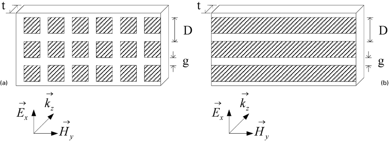
Schematic diagram of metamaterial absorbers under consideration: reproduced with permission from Ref. 323, copyright 2009, American Institute of Physics
With the periodic and symmetric characteristics and taking into account of the metamaterial absorbers comprising of strip arrays, the computational model was deduced as a parallel plate waveguide as shown in Fig. 43.347 Mode matching method was then used to efficiently solve the EM response of the metamaterial absorbers. With a proper fitness function defined related to the absorption bandwidth, genetic algorithm can be effectively used to optimise the performances of the metamaterial absorbers.347
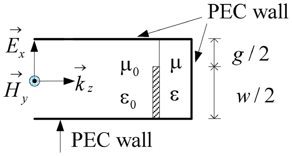
Computational model of metamaterial absorbers in Fig. 42b (w = D−g): reproduced with permission from Ref. 347, copyright 2009, The EMs Academy.
Owing to the image effect caused by the conducting ground plane in the metamaterial absorbers, as shown in Fig. 44, the strips and their images effectively formed strip pairs which worked similarly as SSPs.294,347 – 350 The scattering parameters of the structure in Fig. 44 can be solved by using the mode matching method. As shown in Fig. 45, the effective μ of the strip pairs retrieved by using the approach in Ref. 351 show a strong magnetic resonance in the metamaterial absorbers.
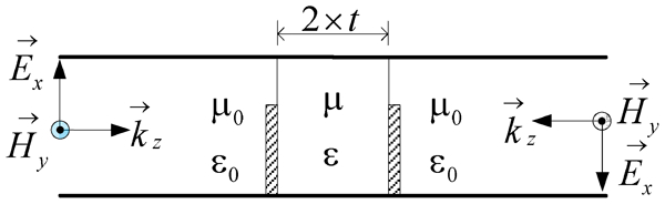
Equivalent computational model of the metamaterial absorbers as in Fig. 46: reproduced with permission from Ref. 347, copyright 2009, The EMs Academy
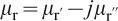
Retrieved effective relative permeability (


An accurate analytical formula for reflection coefficients was derived in Ref. 323, based on strip type of the metamaterial absorbers with normal incidence (see Fig. 42b
), which can be written as follows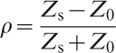
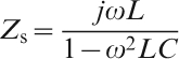

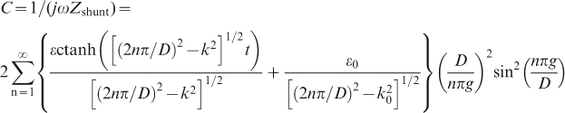
As mentioned above and shown in equation (26), Z
tml is inductive for ultra thin metamaterial absorbers. The inductance L is determined by permeability and thickness of the substrate. The shunt impedance Z
shunt can be characterised by the capacitance C shown in equation (27). The ctanh function containing the substrate thickness t clearly indicates an interaction between the conducting ground plane and the periodic patterns. From equation (25), it can be seen that equivalent circuit of the metamaterial screens is composed of an inductor L (L′−jL″) and a capacitor C (C′−jC″) in parallel. With certain manipulation, the equivalent circuit can be transformed into an RLC circuit shown in Fig. 46. The parameters of the equivalent circuit shown in Fig. 49 can be written as follows
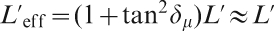
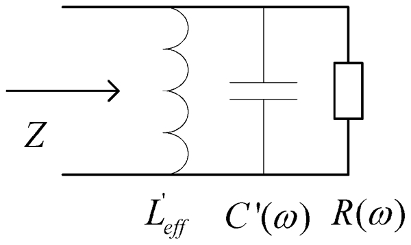
Equivalent circuit of metamaterial screens: reproduced with permission from Ref. 323, copyright 2009, American Institute of Physics
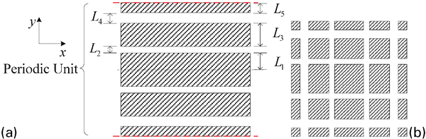
Illustrations of periodic units of metamaterial absorbers with non-uniform patterns
In Ref. 322, a simple analytical model was proposed for similar structures to that shown in Fig. 42. Based on the analytical models for thin strip grids combined with the approximate Babinet principle for planar grids located at a dielectric interface, analytical expressions were derived for the grid impedance of capacitive strips and square patches, i.e. Z shunt. The surface impedance and the reflection coefficients can then be obtained according to equations (23) and (24) respectively. Since Z shunt was derived without considering the conducting ground plane, the model neglected the coupling between the metallic patches and the ground plane. As can be found in Refs. 323 and 352, when thickness of the substrate is small, the transmission line model will produce great errors if the coupling is neglected.
Bandwidth limits of ultra thin metamaterial absorbers, with frequency non-dispersive and frequency dispersive substrates, were investigated in Ref. 323. Since ultra thin metamaterial absorbers are narrow banded, in many cases μ and ϵ of the substrates can be regarded as frequency non-dispersive in the absorption band. In this case, the maximum bandwidth of ultra thin metamaterial absorbers was found to be323
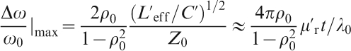

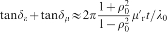
Equation (30) indicates that the maximum bandwidth is not related to the real part of permittivity ϵ′. Actually, substrates with different values of real permittivity ϵ′ can be used to design ultra thin metamaterial absorbers with the same physical thickness to achieve the same maximum fractional bandwidth as long as the loss tangents are appropriate to meet the requirements given by equation (31).323 It is noted that for Dallenbach absorbers the thickness is approximately λ/4. Thus for smaller ϵ′, the physical thickness of the substrate has to be increased. However, for metamaterial absorbers, since the maximum bandwidth is not related to ϵ′, the substrate of a given physical thickness can be fabricated with a wide variety of materials. Furthermore, according to the maximum bandwidth expressed in equation (1) derived by Rozanov10 for normal frequency non-dispersive dielectric Dallenbach absorbers, it can be found that the maximum bandwidth of metamaterial absorbers is ∼1·2 times that of the Dallenbach absorbers.
If the equivalent circuit components in Fig. 46 are strongly frequency dispersive in the absorption band, equations (30) and (31) are no longer valid. If μ and/or ϵ are decreasing with increasing frequency so that the equivalent LC circuit in Fig. 46 resonates over a broad band, large absorption bandwidth can be possibly achieved when the resistive component R in Fig. 46, which is mainly determined by loss tangent of the substrates, is close to the wave impedance in free space. Examples are given as follows for metamaterial absorbers with dielectric substrates. The relative permittivity of physically realisable dielectrics can be expressed as summation of n resonant terms as follows10
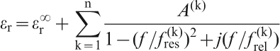
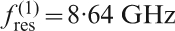
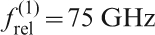
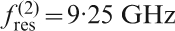
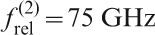

Permittivity with different frequency dispersion (solid lines: ϵrwith one resonant term; dash lines: ϵr with two resonant terms; dash dot lines: constant ϵr; dot line in a: ideal


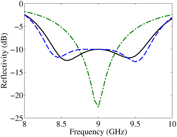
Reflectivity of metamaterial absorbers made of dielectric substrates with different frequency dispersion (solid line: one resonant term; dash line: two resonant terms; dash dot line: frequency non-dispersive): reproduced with permission from Ref. 323, copyright 2009, American Institute of Physics
As pointed by Rozanov, the absorption performance of normal grounded slab absorbers is determined by the following expression10
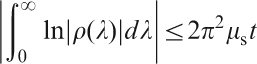
From equation (33), we can get323
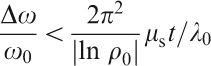
By comparing equations (30) and (34), it can be found that the limit of the bandwidth is increased greatly by replacing the frequency non-dispersive substrates with appropriate frequency dispersive ones.
In Ref. 347, metamaterial absorbers were proposed by using non-uniform conducting strip arrays or rectangular patches arrays, whose periodic units are illustrated in Fig. 49. The non-uniform conducting arrays provided multiple resonances. As shown in Fig. 50, two absorption peaks are observed. Therefore, the metamaterial absorbers with non-uniform arrays have broader absorption bandwidths than those with uniform arrays. However, the periodicity of the non-uniform arrays is much larger than that of the uniform arrays. As a result, grating lobes341 shift to much lower frequencies.
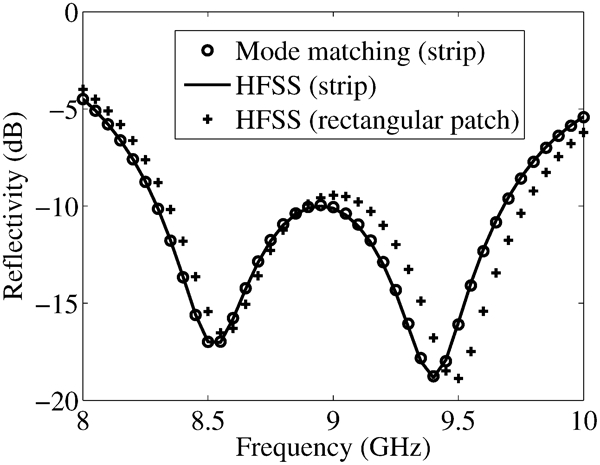
Simulated reflectivity of metamaterial absorbers with non-uniform conducting arrays on top of 0·8 mm dielectric substrate (ϵ = 5·44×(1−0·1j)ϵ0, L 1 = 3·1 mm, L 2 = 0·4 mm, L 3 = 5·5 mm, L 4 = 1·0 mm, L 5 = 2·8 mm)
The bandwidth could be increased by incorporating magnetic materials with high permeability,312,323 but at the expense of increased weight. As demonstrated in Figs. 49 and 50, and in Refs. 337, 338 and 353–358, multiple resonance can be created in metamaterial absorbers by combining units with different resonant frequencies, so as to achieve broadband absorption. The absorption bandwidth can also be expanded by matching the effective lossy permeability and permittivity in a broadband, as demonstrated by Gu et al. in Ref. 359. As shown in Ref. 323, it is also possible to expand the absorption bandwidth by using frequency dispersive materials as the substrate of the resonant units.
It is well known that the absorption bandwidths of currently available metamaterial absorbers with conducting ground planes are still much below the theoretical limit. A practical approach to expand the bandwidth of metamaterial absorbers is to push it as close as possible to the theoretical limit.
Smart metamaterials and structures with tunable EM responses
Tuning mechanisms
Besides their inferior bandwidth as stated earlier, EM responses of most metamaterials are not tunable or controllable. Namely, once fabricated, their properties (such as working frequency and amplitude, etc) cannot be modified or altered. This could be a problem in cases where active or tunable responses are required. It is therefore appealing to develop smart or adaptive metamaterials which can be adjusted to have tunable or active responses to variable incident signals.
Tuning of metamaterials with non-linear insertions, such as diodes, varactors, relay or MEMS, has been proposed conceptually and realised experimentally.360 – 365 It has been proved theoretically that a non-linear metamaterials slab can be switched between transmitting and absorbing states by tuning the effective resistance of the resonant conductive elements. Self-tuning mechanism of non-linear split ring resonators with varactor diodes has been investigated theoretically362 and measured with waveguide system.363 Figure 51 shows photograph of a patch arrary metamaterials tunable with varactors.380 It has also been proved that structural tuning (relative shift of staggered lattice) can be used to adjust the resonance over a wide bandwidth.364 The tuning was realised by the staggered lattice shifting with a lateral displacement of every other layer. Similar tuning mechanism has also been used for reconfigurable metamaterials operating at Terahertz frequencies.365 Tunability of the SRR arrays at THz was realised through different bending at heating temperatures from 350 to 500°C.
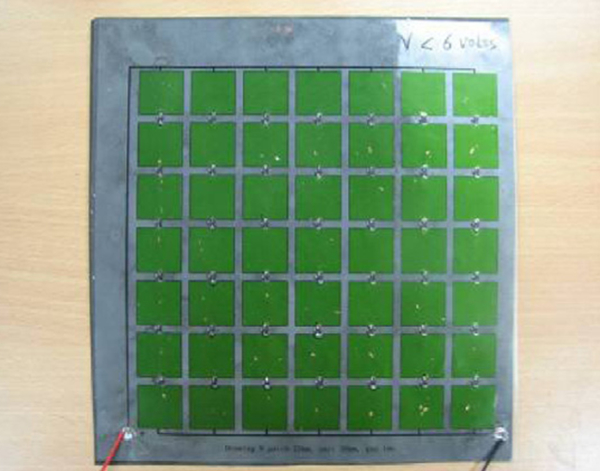
Electromagnetic smart screen with patch array loaded with varactors: reproduced with permission from Ref. 380, copyright 2010, Elsevier
There has been report on metafilm as a two-dimensional metamaterials, constructed by a single layer surface distributed with electrically small scatters characterised by electric or magnetic polarisability densities. A metafilm composed of resonant magnetodielectric spherical particles could be used to achieve controllable surface characteristics through external bias magnetic fields.366 Electrically tuned active frequency selective surface (FSS) loaded with pin diodes has been used to constructed low microwave reflection layer with reflectivity varying as a function of diode bias current.367 – 369 Electrically tunable high impedance surface with periodic surface texture loaded with varactors is able to steer the reflected beam over ±40° in two dimensions which has potential for transmission or reflection applications.370 A reconfigurable beam steering reflector made of similar tunable high impedance surface can be tuned as adjusting the relative position between two layers of the circuit boards.371 The limitation of the mechanically tuned surfaces is that the respond of tuning is not prompt enough to meet the requirement of fast operating.
Electromagnetic smart screens (ESS) containing conductive strip arrays loaded with pin diodes have been studied both numerically and experimentally. Transmission coefficient of such screens can be simulated using the FEM, which has already been validated by free space measurement.372 Tunable EM properties were observed between 3 and 8 GHz, which could find applications in antenna designs. However, only two states, namely on and off, have been investigated.372 Recently, it was found that the effective properties of such metamaterials can be continuously adjusted over certain frequency ranges.373 These metamaterials could be used for both civil and denfence applications, such as hybrid radome, band stop filters, subreflectors and CA absorbers.
To increase tunability of the metamaterials or metafilms, other approaches than loading with electronic components or mechanical movements, have also been employed to tune their microwave responses. Among them, smart materials with electrically or magnetically adjustable properties are commonly combined with periodic metamaterials to achieve certain tunability. Ferroelectric374 or ferromagnetic thin films375 are normally employed as the control units of the smart structures or systems. Comparatively, it is not popular to drive actuators with magnetic field in practical applications, because producing a large and uniform magnetic field is more difficult.
Tunable microwave reflection coefficients of TiO2 coated kaolinite and Y-doped BaTiO3 electrorheological (ER) fluid have been reported.376 It was found that the magnitude of reflection coefficient of the BaTiO3 ER fluid was reduced gradually when the particle concentration was low (25%). It decreased to a minimum value and then increased when the particle concentration was >25%. Recently, CNTs or graphene based components or structures have been paid more attention with potential application for sensor or actuator at microwave, millimetre wave or THz frequencies. For example, large tunability at radiowave frequency was realised in CNT–polymer composites with CNT loading close to the percolation ratio.377
Advantages and limitations of different tuning methods are summarised in Table 14. Although any materials with certain responsive stimulus can be used as the controlling elements of smart metamaterials, tunings with bias electrical field, magnetic field and mechanical force or movement are among the easiest ways currently. The carbon or ER fluid based metamaterials have better power handling capability as compared with those of diodes or varactors which usep–n junctions with certain power limit. However, responding times of the tunable materials could be many times longer than that of diodes due to their difference in the tuning mechanism. Also, the tunability of tunable materials is normally inferior than diodes. So, no single approach could be able to fulfill all of the request from real applications.
Comparison of smart metamaterials with different controlling elements and tuning mechanisms
Tunability of smart metamaterials loaded with diodes
Traditionally, the properties of active FSS or phase switchable screen were calculated based on transmission line model.378 However, the one-dimensional transmission line model does not account the contribution of each scatter and control unit quantitatively. The MOM is a common algorithm to model the induced current of the wire elements in FSS.329 The FEM can be used to model geometries with extreme aspect ratio and anisotropic media, which has been proved by experimental results. It is also found that the FEM has better accuracy than the MOM for thick wire structures and anisotropic materials.372 Typical unit cell of the FSS sheet comprises two strips of conductors, power lines and a diode, as shown in Fig. 52. The diode is modeled using the lumped RLC boundary conditions with the circuit lumped parameters RLC. A plane wave with electric field E parallel to the conductors and wave vector k perpendicular to the layer surface illuminates the model at normal incidence. Boundary conditions of the PML are imposed on the surfaces that are perpendicular to the wave vector. Periodic or linked boundary conditions are applied to the surfaces parallel to the wave vector. The coherent transmission of the composite sheet is obtained from the ratio of the average transmitted electric field intensity to the incident field intensity.
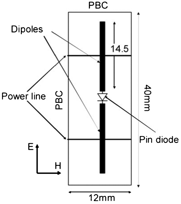
Model of FEM and equivalent circuit of pin diode: reproduced with permission from Ref. 372, copyright 2008, John Wiley & Sons
Since most periodic metamaterials are designed based on resonating elements, shifting resonance frequency and damping the resonance peak could be the most effective ways to adjust the behaviours of metamaterials. These can be realised by tuning the circuit parameters RLC though bias voltages. Qualitatively, the resonance frequency f
res and amplitude A
res are described as a function of the RLC parameters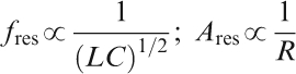
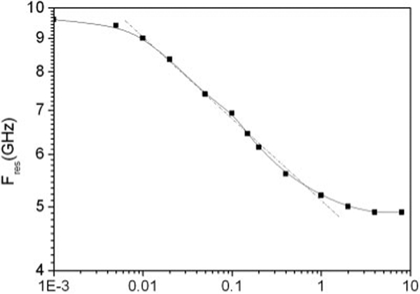
Resonance frequency versus capacitance of component: reproduced with permission from Ref. 372, copyright 2008, John Wiley & Sons
Various EM smart absorbers have been proposed, which use a tunable single layer periodic resonating structure loaded with tunable components, such as varactor and pin diode.379,380 For example, the absorption peak of a patch ESS with thickness of 0·6 mm could be shifted from 4 to 5 GHz with the absorption reduced from 15 to 7 dB when the pin diodes were switched on.379 Patch structure was used because of its strong resonance. Figure 54 shows a unit cell of the smart absorber and equivalent circuit of the pin diode.380 In this study, the reflection coefficient was measured with a free space setup. The measurement setup included a vector network analyser, a power source, vertically mounted broadband transmitting and receiving lens horn antennas, pyramidal absorber and a styrofoam board to hold the sample. They were mounted on a three-deck wooden frame to minimise the unnecessary reflection from the environment. The measurement frequency range was from 2 to 18 GHz. To eliminate multiple scattering between the sample and the horns, time domain gating was applied. Diffraction effects at the edges of the sample were minimised by the absorber attached to the styrofoam board.
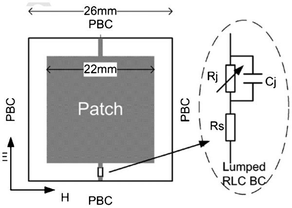
Unit cell of smart absorber and equivalent circuit of pin diode: reproduced with permission from Ref. 380, copyright 2010, Elsevier.
The dependence of absorption on EM parameters (such as permittivity and permeability) of the substrate was investigated numerically in Ref. 380. The resonance frequency is a function of ϵ and μ, according to 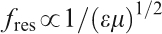
Therefore, tunable responses of smart metamaterials can be realised by shifting the resonance frequencies and reducing the resonance peaks. Shift of resonance peak can be achieved by tuning capacitance or inductance of the control components or changing permittivity or permeability of the substrate. Tunabilities of representative smart metamaterial are summarised in Table 15. Different criteria are used to evaluate tunabable performances of different types of smart metamaterials. Here, Δf res/ f res and ΔA res/A res are used, with meaning shown in equation (35) to evaluate the tunability of smart metamaterials, which was also adopted in Ref. 362.
Advantages and limitations of smart metamaterials with different tuning mechanisms
Metamaterials based on ferrite core and wire coil
Metamaterials with inductive components
Effective permeability produced by resonances in microwave frequency range has been observed in a variety of metamaterials comprising non-magnetic materials such as inductive patterns. For example, effective magnetic responses can be generated by using non-magnetic split ring resonator,283 short wire pairs or short strip pairs,381,385 as shown in Fig. 55a and b . Negative real permeability can be obtained at certain frequency bands. High dielectric constant materials, as well as a combination of conductors and dielectric materials, can also be used as artificial magnetic metamaterials with real effective permeability μ>1.386 – 388
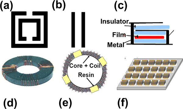
Sketch of inductive patterns for magnetic metamaterials
However, the effective permeability and resonance effect of above mentioned metamaterials without using magnetic components is rather small. To amplify the inductive behaviour of meatmaterials, it is necessary to use magnetic components. Inductive patterns, consisting of Cu coils wound on a magnetic core, have been widely used to produce LC resonances with considerably large imaginary effective permeability.383,384,389 – 394 Recent progress of such metamaterials has been comprehensively reviewed by Acher.382
A tunable metamaterial based on conducting coils loaded with an electric circuit containing a varactor diode was reported by Reynet and Acher.390 As a biased voltage was increased from 1 to 24 V, the varactor could be tuned to be from 15 to 2 pF. The maximum real and imaginary effective permeability of this metamaterial was 2–3, and its resonance frequency f R could be shifted from 0·2 to ∼0·5 GHz. The degree of the shift was dependent on the the number of coil turns. Recently, a metafilm was fabricated by using a magnetic thin film, wrapped into a hairpin-like metallic structure. An insulator was used to prevent electrical contacts between the metal and the magnetic film,394 as shown in Fig. 55c . The metafilm exhibited two resonances, one below the gyromagnetic resonance frequency of the magnetic core and the other at much higher frequency. Large imaginary effective permeability of ∼100 and large negative real effective permeability of −55 at 0·4 GHz were observed. In addition, a torus with inner diameter of 20·9 mm and outer diameter of 22·2 mm, as a magnetic core, was fabricated by gluing bundles of CoFeSiB amorphous microwires. Metamaterial consisting of the core and Cu coils with various turns392,393 was similar to that shown in Fig. 55e . As the number of coil turns was increased from N = 0 to 16, the real and imaginary effective permeability increased and resonance frequency was shifted from 1·3 to 0·2 GHz.
Construction and properties of core–coil metamaterials
With the background discussed above, a metamaterial, consisting of a ferrite core and a set of coil with various turns, has been developed in the authors lab.383 A representative sample is shown in Fig. 55d . Typically, the cores had outer and inner diameters of 13·2 and 7·5 mm respectively, with thicknesses of 0·56–1·80 mm. The cores were wound by a Cu wire coil with 8–32 turns.
Figure 56 shows representatively permeability spectra of the metamaterials with different numbers of coil turns over 100 MHz–1 GHz measured using Agilent E4991A RF impedance/materials analyser with open-short-load calibration. It was found that effective permeability of the metamaterial strongly depends on permeability and permittivity of the core materials, size of the core and number of coil turns.384 Figures 57 and 58 show the dependences of maximum imaginary effective permeability 


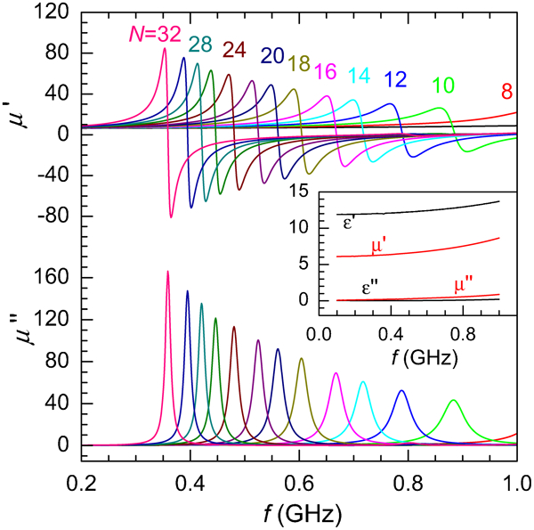
Effective permeability of metamaterial with ferrite core and Cu coil (inset shows permeability and permittivity of ferrite core): core is Z-type hexagonal ferrite, with dimension of outer and inner diameters of 13·2 and 7·5 mm respectively, and thickness is 0·85 cm

Linear dependence of


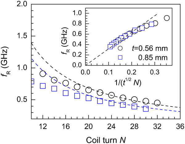
Dependence of f R on N for metamaterial with t = 0·56 and 0·85 mm respectively, where dashed lines show reversely proportional correlation between f R and N (inset: f R is reversely proportional to product of t 1/2 and N for two metamaterials)
Based on the equivalent lumped parameter model, an equivalent capacitance N
2
C
eq is introduced to lump the total effects of the stray capacitance. C
eq acts as a capacitive load of the equivalent transformer. The input impedance can be written as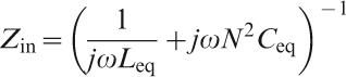
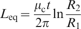
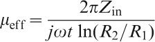


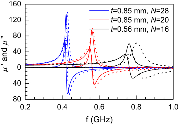
Comparison between measured (solid lines) and calculated (dashed lines) permeability spectra: black lines are for metamaterial with t = 0·56 mm and N = 16, blue and red lines are for those with t = 0·85 mm and N = 28 and 20 respectively; reproduced with permission from Ref. 384, copyright 2009, American Institute of Physics
Permeability theory
In equation (36), both L
eq and C
eq are complex functions. 


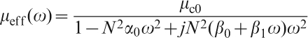


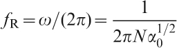
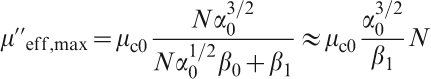
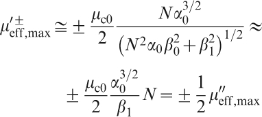
Equations (41) and (42) show that 


Potential applications
Negative permeability materials
Permeability spectra of the metamaterials with ferrite cores and coils exhibit typical resonance-type dispersion with damping coefficients of 0·03–0·17. It is clearly demonstrated by equation (42) that, as long as α
0 is sufficiently high and β
0 and β
1 are sufficiently low, high negative permeability can be obtained, which is confirmed by the results shown in Fig. 56. For example, 
Frequency tunable device
The metamaterial can also be used as frequency switchable device by using two sets of coils connected by a switch. Figure 60 shows measured permeability spectra of such metamaterial with two coils of eight turns. In OFF state, it has a resonance peak at 0·82 GHz, while in ON state, the coils are connected into one coil with 16 turns and the resonance is shifted to 0·46 GHz.
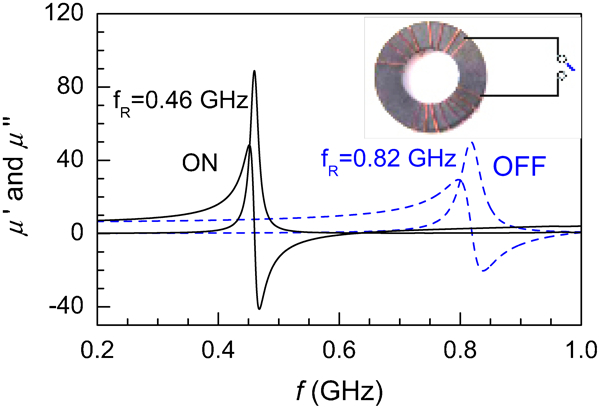
Measured permeability spectra of metamaterial, where solid and dashed lines are corresponding to ON and OFF states respectively: thickness of ferrite core is 1·8 mm
Meta fillers of composites
A meta filler is fabricated by using a thin plate ferrite piece and a coil wound on it. Figure 61 shows photographs of some meta fillers. Composites are fabricated by mixing the meatfillers with polymers (e.g. epoxy or silicone).
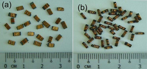
Metafillers consisting of ferrite pieces and Cu wire coils
Figure 62a
shows effective permeability and permittivity of a composite made with silicone and the metafillers with a volume concentration of p = 0·3. The composite has an outer diameter of 14 mm, inner diameter of 6 mm and thickness of ∼2 mm. It has a 

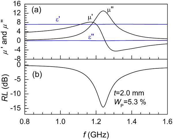
a measured permeability spectra and b predicted reflectivity properties of composite made with silicone and metafillers with volume fraction of p = 0·3
Metamaterials with periodic inductive patterns
A ring type of metamaterial was fabricated by gluing the ferrite coil pieces. An example is shown in Fig. 55e . The ring has outer and inner diameters of 12·5 and 7·5 mm respectively. Length, width and thickness of the ferrite pieces are about 5, 2·5 and 1 mm respectively. Cu wire coil has N = 12.
The complex permeability and permittivity, of the ring metamaterial, measured using PNA with 14 mm coaxial airline, are shown in Fig. 63a
. 

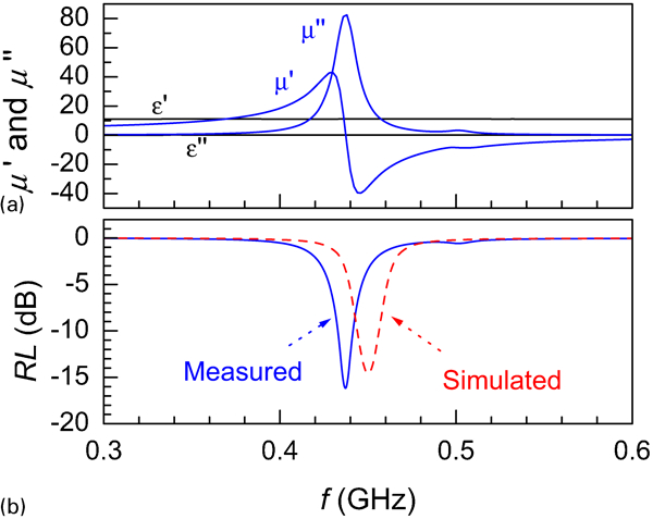
a measured permeability and permittivity spectra and b RL–f curves measured and simulated from permeability and permittivity of composite
Magnetodielectric materials with matching permeability and permittivity
Background
Conventional antennas, of high frequency (2–30 MHz) and VHF (30–90 MHz and 100–300 MHz) bands, have rather large physical sizes. Reducing physical dimensions of these antennas has always been a significant challenge. Many attempts have been made to reduce the physical size of high frequency and VHF antennas via antenna designs. Theoretically, if loaded with magnetodielectric materials, with refraction index n (n = (μ′ϵ′)1/2, where μ′ and ϵ′ are real part of relative permeability and permittivity respectively) lager than 1 (refraction index of free space), antenna’s physical dimensions can be reduced by a factor of n while its electrical dimension keeps unchanged.396,397 Besides high refraction index, the materials should also have impedance matched to free space (Z = (μ′/ϵ′)1/2 = η 0, with μ′ = ϵ′, where η 0 is the impedance of free space), as well as sufficiently low dielectric and magnetic loss tangents, for practical applications. However, such materials have not been found in nature.
Some years back, a chessboard structure, which comprised of both magnetic and dielectric components, was proposed by Yu et al. 398,399 Matching permeability and permittivity can be obtained by adjusting the proportions of the magnetic and dielectric components.398,399 However, no practical materials based on such a structure have been reported to date. In this regard, we attempted to use composite materials to achieve the properties similar to the proposed chessboard structure. Relatively, it is easy to adjust the dielectric properties of composites, since materials with high dielectric constants in the frequency bands of interest are enormously available. The main challenge is to find appropriate magnetic components. Among magnetic materials, magnetic metal alloys usually have very high conductivity, leading to composites with permittivity much higher than permeability, and thus are not suitable for this purpose. As a result, it is more practical to use ferrites for the preparation of this class of composites. Preliminary results of Kong et al.400,401 showed that composites based on Ni–Zn–Co ferrite powders had close values of permeability and permittivity of ∼6. These composites had problems in two aspects. First, their dielectric loss tangent was relatively high, which was attributed to the high loss tangent of the epoxy matrix. Second, the low magnetic loss frequency was not higher than 30 MHz. To address these problems, ferrite ceramics were then used.
There are three types of ferrites: spinel, garnet and hexaferrite. The resonant frequencies of composites based on spinel and garnet ferrites are several hundreds of MHz, while that of hexaferrites are in the microwave band. Therefore, it is possible to use spinel or garnet ferrite for low frequency applications, and hexaferrites for microwave design. Various spinel ferrites, including MgFe2O4,402 – 405 Li0·50Fe2·50O4,406 – 408 and Ni1−xZnxFe2O4,409,410 with almost equal real permeability and permittivity of 6–15, over 2–30 MHz and 30–90 MHz, have been reported. To achieve low magnetic loss tangent, the materials must have a resonant frequency far beyond the desired frequency band, while for low dielectric loss, ferrites must be fully sintered at low temperatures, as discussed late.
Ferrite–polymer composites
Spinel ferrite powders, including Ni0·75−xCoxZn0·25Fe1·90Mn0·02O4 (x = 0, 0·05 and 0·10), Ni0·95−xCo0·05ZnxFe1·90Mn0·02O4 (x = 0–0·25) and Li0·50−0·5x M xFe2·50−0·5xO4 (x = 0, 0·1–0·5, M = Mg and Cu), have been used to fabricate composites with epoxy. The ferrite powders were synthesised via the conventional solid-state reaction process or molten salt technique.
Figure 64 shows representative magnetic dielectric properties of an epoxy composite with 50 vol.-%Ni0·70Zn0·25Co0·05Fe1·90Mn0·02O4 powder. The ferrite powder was synthesised first from corresponding oxide precursors and then was treated in Na2SO4 flux at 1200C for 2 h, where ferrite powder versus Na2SO4 weight ratio was 1∶2. The ferrite powder had regular grains with an average grain size of ∼5 μm. This composite has very close real permeability and permittivity (∼6·8) over 2–30 MHz (high frequency band). In this frequency range, the composite has a sufficiently low magnetic loss tangent but a relatively high dielectric loss tangent. The high dielectric loss tangent of the composite has been attributed to the high loss tangent of the epoxy matrix. Furthermore, the frequency band of low magnetic loss tangent cannot be higher than 30 MHz by using whatever spinel ferrites. To address these problems, it is necessary to use ferrite ceramics.
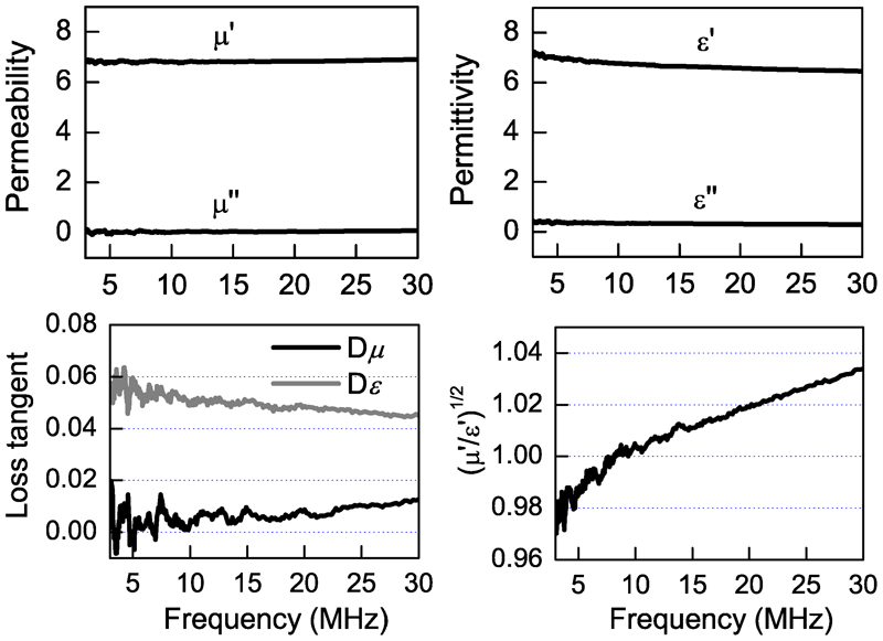
Representative magnetic dielectric properties of 50 vol.-% spinel ferrite epoxy composite
Ferrite ceramics
Mg ferrite based ceramics
Magnesium ferrite (MgFe2O4) has a cubic spinel type structure, with a lattice constant of a = 0·83998 nm and space group 
Pure MgFe1·98O4 ceramics was found to have close permeability and permittivity of 6 and very low magnetic and dielectric loss tangents, over 2–30 MHz (high frequency band). The MgFe1·98O4 ceramics was sintered at 1125°C with a density of 3·1 g cm−3, which is ∼68·5% of its theoretical density (4·523 g cm−3). This can be attributed to the fact that MgFe1·98O4 ceramics has a poor sinterability. For real applications, materials with poor densification may suffer from mechanical problems. Almost fully dense MgFe1·98O4 ceramics should be sintered at temperatures of >1200°C. However, high temperature sintering would lead to high dielectric loss tangent of ferrite ceramics, due mainly to the formation of Fe2+, which increased the conductive loss and hence the total dielectric loss tangent. Therefore, to develop ferrite ceramics with low dielectric loss tangent, it is necessary to improve their sinterability.
Using sintering aids is one of the most popular techniques to improve the sintering behaviours of various materials. Various sintering aids have been used for ferrite ceramics in open literature.414 – 427 CuO and Bi2O3 are two representative sintering aids for ferrite ceramics. CuO can be incorporated into the chemical formula of spinel or barium ferrites. CuO was reported to decompose into Cu2O, which has a low melting point. In the presence of Cu2O, a eutectic Cu rich liquid phase may be formed at even lower temperatures than the melting point of Cu2O. This cu rich liquid phase provided an environment to facilitate liquid phase sintering. Specifically, Bi2O3 is not able to enter lattice of spinel ferrites. However, similarly, with a low melting point (∼820°C), Bi2O3 forms liquid phase layer during sintering at high temperatures and thus also providing liquid phase sintering.
Sintering behaviour, grain growth, magnetic and dielectric properties of Mg1−xCuxFe1·98O4 ceramics have been systematically studied.402,403 It was found that, with increasing content of Cu from x = 0·1 to x = 0·30, shrinkage onset temperature of the samples gradually decreased, with peak shrinkage rate decreasing from 1214 to 1055°C. Comparatively, the shrinkage onset temperature of MgFe1·98O4 was >1250°C. It was very easy to attain 95% of their theoretical densities for Mg1−xCuxFe1·98O4 ceramics, while the relative density of MgFe1·98O4 was only 94% after sintering at 1250°C for 2 h. Typically, the sintering temperatures of Mg1−xCuxFe1·98O4 were nearly 200°C lower than that of MgFe1·98O4.
The Mg1−xCuxFe1·98O4 ceramics also processed different microstructures from MgFe1·98O4. The poor densification behaviour of MgFe1·98O4 is probably attributed to the presence of rigid skeleton structure with many point contacts, which requires a high temperature to collapse. The introduction of Cu not only altered the densification behaviour of MgFe1·98O4, but also promoted its grain growth. For example, the grain sizes of MgFe1·98O4 ceramics were <3 μm after sintering at 1250°C for 2 h, which were almost an order of magnitude smaller than those of Mg1−xCuxFe1·98O4.
The average grain size of the Mg1−xCuxFe1·98O4 ceramics did not show a monotonic increase with Cu concentration. At a given sintering temperature, the average grain size was maximised at x = 0·20. The variation in grain size for Mg1−xCuxFe1·98O4 ceramics was explained in terms of the mechanism for the grain growth. During liquid phase sintering, grain growth occurs via a dissolving/solution precipitation process. Energetically, small grains are less stable than large ones due to their higher specific surface area. As a consequence, small grains would be dissolved in the liquid phase layers. Once the concentration of the dissolved phase reached a critical level, precipitation took place. This means that larger grains grow at the expense of smaller grains. It also means that small grains have to ‘swim’ through a barrier (liquid phase layer) to combine with a large grain. At low concentration (x<0·2), it is understood that an increase in the amount of Cu resulted in an increase in the coverage of the grains by the liquid phase layers, and this was beneficial to grain growth. As a result, the average grain size increased with increasing concentration of Cu. Once a critical point was reached at which all grains were covered by the liquid phase, further increase in the Cu concentration would lead to an increase in the thickness of the liquid layers. An increased thickness of the liquid layers means a widened diffusion path, i.e. it would take longer time for smaller grains to reach the larger ones. Hence, the grain growth rate of the samples above the critical concentration of Cu would be lower than that of the samples below the critical concentration of Cu. In other words, the amount of the liquid phase became saturated when its concentration reached the critical point (x = 0·20).
Electrical properties of ferrite ceramics are closely related to their microstructures. Direct current resistivity is one of the most important parameters of ferrite ceramics. In general, high resistivity is required for most applications. The dc resistivities of ferrite ceramics are determined by several mutually related factors, including composition, density (porosity), grain size, crystal structure perfection, microstructural homogeneity and impurity levels. The presence of porosity usually increases the dc resistivity of ferrite ceramics, since air/vacuum is a good insulator if the pores are closely trapped and uniformly distributed. Otherwise, porosity can reduce resistivity of ferrite ceramics. Another factor that greatly reduces the dc resistivities of ferrite ceramics is the formation of Fe2+ ions, due to electron hopping between Fe2+ and Fe3+. As the transfer of electrons from Fe2+ ion to Fe3+ ion occurs within the octahedral sites, it does not cause a change in the energy state of the crystal as a result of the transition. The abrupt drop in dc resistivity after sintering at 1250°C was due mainly to the formation of Fe2+ ions.402
The difference in microstructure between MgFe1·98O4 and Mg1−xCuxFe1·98O4 can be used to explain their difference in DC resistivities. MgFe1·98O4 and Mg1−xCuxFe1·98O4 had different porous characteristics. MgFe1·98O4 sample had a rigid skeleton structure, while Mg1−xCuxFe1·98O4 sample comprised rounded grains that were loosely compacted together. The pores in MgFe1·98O4 were isolated while the pores in Mg1−xCuxFe1·98O4 were interconnected. Consequently, the porosity of MgFe1·98O4 acted as an insulator, whereas the porosity of Mg1−xCuxFe1·98O4 could form easy conduction paths when conductive impurities (such as H2O) were trapped.
High frequency permittivity of ferrite crystals is mainly due to the atomic and electronic polarisation in the ceramic grains. The permittivity of polycrystalline ferrite ceramics is further affected by their microstructure, grain size, density and the presence of impurities. The dependence of permittivity on grain size is explained by the Maxwell–Wagner effect,428 where ferrite ceramics are considered to comprise conductive grains separated by layers (grain boundaries) of lower conductivity. The increase in grain size reduces the volume fraction of the grain boundaries, resulting in an increased permittivity. Porosity (density) also has a double sided effect on the permittivity. Close pores (interior grains or at grain boundaries) will reduce the permittivity because the dielectric constant of air (pores) is 1. Open (interconnected) pores, with absorbed impurities (e.g. water) may increase the permittivity, due to the high dielectric constant of water. Structural defects/imperfections would also increase the polarisation.
The presence of Fe2+ in ferrites always leads to high permittivity because Fe2+ has a larger polarisation than Fe3+. Fe3+ ion has a stable d-shell configuration with spherical symmetry of the charge cloud, due to its five d-electrons distributed according to Hund’s rule, whereas Fe2+ ion has an extra electron as compared to Fe3+, which disturbs the symmetry of the electron cloud. As a result, the presence of Fe2+ increases the polarisation in ferrites. Hence, ferrites with a larger number of Fe2+ ions are likely to exhibit higher permittivity.
Dielectric loss tangent of polycrystalline ferrite ceramics is determined by several factors, for example, microstructures and the presence of impurities and imperfection in the ferrite structure. However, the most significant contribution to dielectric loss tangent comes from the conduction loss due to electron hopping between Fe2+ and Fe3+ ions, especially at low frequencies. In this respect, the increase in permittivity due to the presence of Fe2+ ions is generally undesirable because it is always accompanied by an extremely high dielectric loss tangent.
Owing to their improved densification and grain growth, Mg1−xCuxFe1·98O4 always had higher permittivity than MgFe1·98O4. A jump in permittivity and dielectric loss tangent (especially at low frequencies) is observed in the MgFe1·98O4 and Mg1−xCuxFe1·98O4 samples as the sintering temperature is increased from 1200 to 1250°C and 1100 to 1150°C, respectively. This was attributed to the formation of Fe2+ ions. The relative permittivity of Mg1−xCuxFe1·98O4 increased almost monotonically with increasing Cu concentration and sintering temperature. The increasing trend in relative permittivity was attributed to the increased grain size and improved densification due to the presence of Cu. The critical concentration of Cu was not observed in the permittivity of Mg1−xCuxFe1·98O4, probably due to the less pronounced porosity effect.
It was found that the concentration of Cu had no significant impact on magnetic properties (complex permeability) of the Mg1−xCuxFe1·98O4 ceramics. The effect of sintering temperature on complex permeability of the ferrites was well explained by a magnetic circuit model.64,403 The Mg1−xCuxFe1·98O4 ceramics had no very promising magneto-dielectric properties, due to their relatively high dielectric loss tangent. In this respect, CuO is not good enough as a sintering aid for ferrite ceramics in case that low dielectric loss tangent is a critical dielectric parameter.
Further improvement in dielectric and magnetic properties of Mg1−xCuxFe1·98O4 ceramics was achieved by introducing Co to form Mg0·90−x−yCoxCuyFe1·98O4. A representative example was Mg0·90−x−yCoxCuyFe1·98O4 (y = 0·10). As a result of the addition of Co, DC resistivity was increased by nearly an order of magnitude for the samples sintered at lower temperatures (1050 and 1100°C).403 This was attributed to the fact that the presence of Co altered the conduction mechanism of the ferrite ceramics. With the substitution of Co in ferrites, p-type conduction takes place via the hole transfer between Co2+ and Co3+,429,430 which compensates for the n-type conduction of the host ferrites. At a given sintering temperature, the permittivity of Mg0·90−xCoxCu0·10Fe1·98O4 decreases almost constantly with increasing concentration of Co.
The magnetocrystalline anisotropy of most spinel ferrites is a relatively smaller negative value. Co ions contribute larger positive magnetocrysalline anisotropy. Introduction of Co is able to compensate or change the magnetocrystalline anisotropy of the host ferrites. Specifically, the Mg0·85Co0·05Cu0·10Fe1·98O4 ceramics sintered at 1100°C for 2 h, had almost permeability and permittivity of ∼10, with both magnetic and dielectric loss tangents of <0·01, over 2–30 MHz. Therefore, the refraction of Mg0·85Co0·05Cu0·10Fe1·98O4 (n = 10) is fairly higher than that of MgFe1·98O4 (n = 6).
Li ferrite based ceramics
Li0·50Fe2·50O4 has a high Curie temperature (670°C), high resistivity and low magnetic and dielectric losses.406 – 408 However, pure Li0·50Fe2·50O4 cannot be fully sintered at temperature of <1100°C, due to its poor densification characteristics. The effect of Bi2O3 on densification, microstructural development, dielectric and magnetic properties of Li0·50Fe2·50O4 ceramics has been systematically investigated.406 – 408
As shown in Fig. 65, 1 wt-%Bi2O3 brought down the linear shrinkage peak temperature of Li0·50Fe2·50O4 from ∼1100 to 900°C and increased significantly the maximum shrinkage rate and the final linear shrinkage of Li0·50Fe2·50O4 406 The enhancement in densification was also clearly demonstrated by the measured densities of the ferrite ceramics, as shown in Fig. 66, and representative SEM images shown in Fig. 67.406 Combined with the grain growth behaviors of the materials, this improvement was readily attributed to the presence of liquid phase sintering mechanism with the addition of Bi2O3, which is similar to that observed in the Mg1−xCuxFe1·98O4 ceramics discussed above.
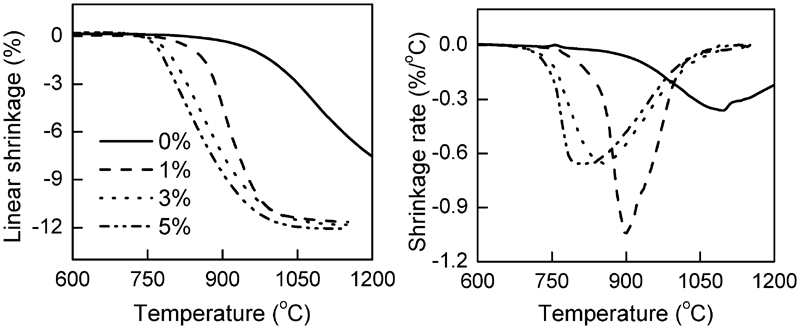
Sintering behaviours of Li0·50Fe2·50O4 ceramics with different concentrations of Bi2O3: reproduced with permission from Ref. 406, copyright 2008, Elsevier
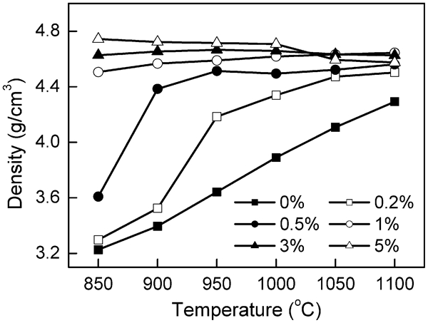
Densities of Li0·50Fe2·50O4 ceramics with different amount of Bi2O3 as function of sintering temperature: reproduced with permission from Ref. 406, copyright 2008, Elsevier
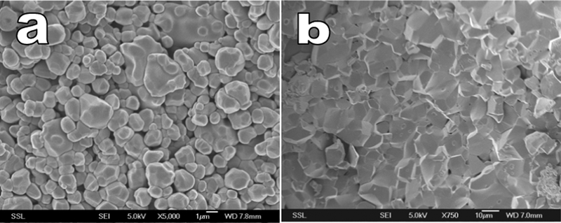
Representative SEM images of Li0·50Fe2·50O4 ceramics sintered at 1000°C for 2 h a without Bi2O3 and b with 1%Bi2O3: reproduced with permission from Ref. 406, copyright 2008, Elsevier
Direct current resistivities of the Li0·50Fe2·50O4 ceramics as a function of the contents of Bi2O3 were found to be quite interesting. As shown in Fig. 68, there was a minimum in resistivity was observed in the samples with 0·2%Bi2O3, almost irrespective with the sintering temperature.407 As the concentration of Bi2O3 was increased from 0·2 to 5%, the resistivity was increased by nearly three orders of magnitude. The relatively low resistivities of pure Li0·50Fe2·50O4 and those with lower concentrations of Bi2O3, sintered at low temperatures, were due mainly to their poorly densified microstructures. Their loose compact microstructure of indicated the presence of open pores, which could absorb water vapors or other contaminants and thus decreased their dc resistivities.
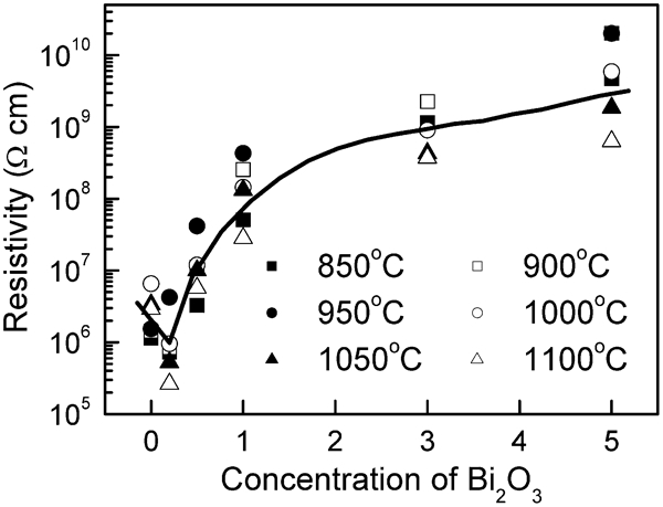
Direct current resistivities of Li0·50Fe2·50O4 ceramics sintered at various temperatures as function of concentration of Bi2O3 (solid line is guided for eyes): reproduced with permission from Ref. 407, copyright 2008, Elsevier
The dispersion of resistivity and dielectric constant of ferrite ceramics can be simply described by using the Koops model.99 In this model, polycrystalline ferrite ceramics are considered to consist of well conducting grains (with diameters of d
2 and resistivity of ρ
2 separated by layers of lower conductivity (with thickness of d1
and resistivity of ρ
1).431 As 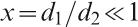

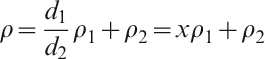
But this model was not able to explain the minimum resistivities of the samples with 0·2%. To understand this exception, it is necessary to closely examine the microstructure evolution of the Bi2O3 doped Li0·50Fe2·50O4 ceramics. It was a multistep process. First, a liquid phase was formed during heating of the materials above the melting point of Bi2O3. The liquid layer surrounded and wetted grains by filling at grain boundaries. Second, densification and grain growth occurred in the presence of the liquid phase during heating and dwelling. Finally, during cooling process, the Bi2O3 rich liquid phase retracted from the two grain boundaries to triple and multiple grain junctions. The degree of retraction was dependent on the amount of the liquid phase.
It was expected that there should be a critical concentration below which all the liquid phase would be brought to grain junctions so that there would be no more liquid phase left at the two grain boundaries. In this case, the two grain boundaries became clean, as was reported in Mn–Zn ferrite.418 Samples with clean grain boundaries were expected to have low resistivities, because both x and ρ 1 in the above mentioned formula become smaller. This could be the possible reason why the dc resistivities of the 0·2% samples are lower than those of the pure ones.
This assumption was supported by dielectric properties of the 0·2%Bi2O3 doped Li0·50Fe2·50O4 ceramics. As shown in Fig. 69, the sample sintered at 1100°C for 2 h had an extremely high real and imaginary permittivity, especially at low frequencies. With a similar model mentioned above, the static value ϵ
s of the apparent relative permittivity ϵ
r of polycrystalline ferrite ceramics can be given by432
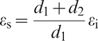
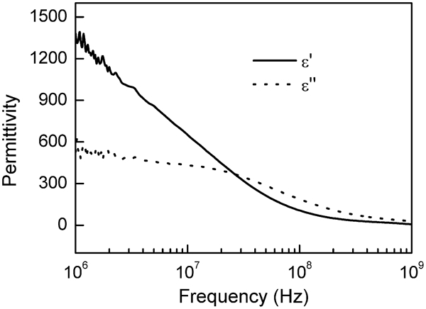
Complex permittivity of 0·2%Bi2O3 doped Li0·50Fe2·50O4 ceramics sintered at 1100°C for 2 h: reproduced with permission from Ref. 407, copyright 2008, Elsevier
Real permeability of the Li0·50Fe2·50O4 ceramics with promising dielectric properties was much higher than their permittivity. To bring down permeability of the ferrite, Co was used to substitute Li in the form of Li0·50−0·50xCoxFe2·50−0·50xO4 (x = 0–0·07). The static permeability values, of the Li0·50−0·50xCoxFe2·50−0·50xO4 samples, sintered at different temperature, as a function of concentration of Co, are depicted in Fig. 70.408 The increase in permeability with increasing sintering temperature at a given composition was attributed to the increase in grain size of the materials. The variation trend in static permeability was explainable by both the single-ion model and the domain wall stabilisation effect of Co ions.
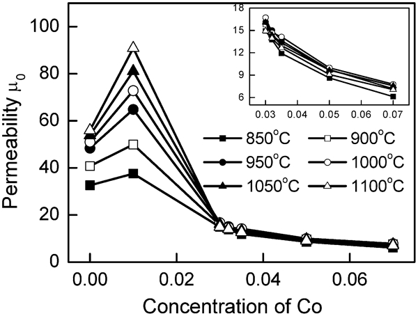
Real permeability (at 1 MHz) of Li0·50−0·50xCoxFe2·50−0·50xO4 ceramics sintered at different temperature as function of concentration of Co (inset shows curves of real permeability versus concentration of Co over x = 0·03–0·07): reproduced with permission from Ref. 408, copyright 2008, Elsevier
In Li0·50Fe2·50O4, Li and Fe ions contributed to negative magnetocrystalline anisotropy, while Co ion provided a very large positive anisotropy. Therefore, when a small amount of Co was added into Li0·50Fe2·50O4, its total magnetocrystalline anisotropy would be varied from a negative value to a positive value. In this case, the absolute anisotropy would experience a minimum at a certain concentration of Co. Permeability of a polycrystalline ferrite is contributed by domain wall motion and spin rotation.433 The permeability due to spin rotation can be expressed as: 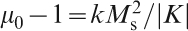
The effect of Co ions on domain wall stabilisation should also be taken into account. The ordering of Co2+ ions at B sites of spinel structure induced local uniaxial anisotropy (Ku), especially in the presence of cation vacancies. Co substitution usually produces p-type conduction in ferrite, due to the electron transfer between Co2+ and Co3+. As a Co2+ is oxidised to a Co3+, a cation vacancy is formed. Therefore, Co ions have a function to immobilise domain walls. The locally induced anisotropy caused by the cation vacancies also increases with Co concentration. This additional effect made the maximum permeability happen at lower concentrations of Co. Moreover, Co3+ ions acted as a pinning centre to immobilise domain wall movement, which also made permeability to start decreasing at lower concentration of Co. Collectively, the maximum permeability appeared at x = 0·01 instead of 0·05.
Representative magnetodielectric properties of the Li0·50−0·50xCoxFe2·50−0·50xO4 (x = 0·032) ceramics sintered at 900°C for 2 h are shown in Fig. 71.408 It was found that the samples with Co concentration between x = 0·030 and x = 0·035 possessed promising magnetodielectric properties. The real permeability and permittivity ϵ′≈μ′≈13−15) of the Li–Co ferrite ceramics obtained in the present study were higher than those of ferrite composites (ϵ′≈μ′≈6−7)400,401 and Mg ferrite based ceramics (ϵ′≈μ′≈6−12)402 – 405 discussed above.
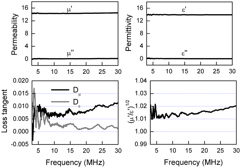
Magnetodielectric properties (over 3–30 MHz) of Li0·50−0·50xCoxFe2·50−0·50xO4 (x = 0·032) ceramics sintered at 900°C for 2 h: reproduced with permission from Ref. 408, copyright 2008, Elsevier
Ni ferrite based ceramics
The effect of Bi2O3 on the properties of nickel ferrite (NiFe1·98O4) ceramics is similar. Pure NiFe1·98O4 cannot be fully sintered at temperatures of below 1200°C. The addition of 3%Bi2O3 led to full densification of NiFe1·98O4 ceramics at 1050°C.409 To obtain a dielectric loss tangent of <10−2, the concentration of Bi2O3 should be higher than 5%, which was higher than that required by Li0·50Fe2·50O4. The sample doped with 5%Bi2O3, sintered at 1050°C for 2 h, had promising magnetodielectric properties, together with sufficiently low magnetic and dielectric loss tangent. Its real permeability and permittivity were ∼12 over 3–30 MHz. Modification of NiFe1·98O4 with small amount of Co further improved its magnetic and magnetodielectric properties. For example, magnetic dielectric tangent of the Ni0·99Co0·01Fe1·98O4 ceramics sintered at 1050°C for 2 h was reduced by two time as compared to that of NiFe1·98O4. The matching frequency of Ni0·98Co0·02Fe1·98O4 ceramics was extended up to 90 MHz (VHF band), which was not achievable in Mg ferrite and Li ferrite based ceramics.
Nanosized ferrite ceramics
The above mentioned achievements indicate that it is difficult to develop magnetodielectric materials with matching real permeability and permittivity up to 100 MHz by using spinel ferrite ceramics processed via the conventional ceramic processing technique. Recent studies demonstrated that the matching frequencies of ferrites could be significantly pushed up by using nanosized ceramics. For example, a nanosized ferrite ceramic with a composition of Ni0·35Zn0·35Co0·2Mn0·05Fe1·98O4 possessed almost equal permeability and permittivity of ∼6, with magnetic loss tangent of 0·03 and dielectric loss of 0·008, over a frequency range of up to 200 MHz.435 The nanosized ferrite ceramics was derived from a fine powder prepared by a coprecipitation method, with a calcination temperature of 800°C and a sintering temperature of 900°C. A further extension in matching frequency up to 700 MHz was realised by using nanosized ferrite ceramics of Ni0·5Zn0·3Co0·2Fe2O4.436,437 Their real permeability and permittivity were ∼5. In a latest report,438 the same authors developed a Ni–Zn nanosized ferrite ceramics, by using a small amount of Cu, i.e. Ni0·4Zn0·4Co0·2Cu0·02Fe1·98O4, which required a sintering temperature of as low as 900°C. The nanosized ferrite ceramics had unchanged permeability of 10·8 and permittivity of 6·5, with a magnetic loss tangent of 0·04 and dielectric loss tangent of 0·006, up to 200 MHz. Since the impedance is 1·3, which is higher than 1, it is still possible to further extend the upset frequency by introducing more content of Co.
Comparatively, barium ferrite ceramics have not been widely reported to show promising magnetodielectric properties. It was mentioned that matching real permeability and permittivity of 26 can be obtained in Z-type barium ferrite, with low loss tangent up to 500 MHz,396 but only magnetic properties were presented, no dielectric properties were available. Generally, barium ferrites have higher dielectric constant than most spinel ferrites due to the high dielectric polarisation of Ba2+ ions and higher resonant frequencies due to their large magnetocrystalline anisotropy. Therefore, barium ferrites would provide higher refraction index and thus would be more efficient for antenna miniaturisation and can push the applications to higher frequencies, which could not be achievable by using spinel ferrites. However, the phase formation and sintering temperatures of barium ferrites are higher than those of spinel ferrites. High temperature processing would inevitably promote the formation of Fe2+ ions, leading to high conductivity and high dielectric loss tangent. In this respect, to achieve low dielectric loss barium ferrite ceramics, they should be either sintered in O2 environment or annealed at low temperatures in O2 after normal sintering.
Potential applications in antenna miniaturisation by using this class of materials have been reported in the open literature,440,441 which is not within the scope of this paper.
Conclusions
Composites made with ferrites, especially those with hexagonal structures, have been shown to be among the most promising candidates for microwave attenuation and shielding applications, due to their advanced EM properties. Microwave performance of a composite is determined by its magnetic and dielectric properties. Magnetic and dielectric properties, including resonance frequencies, complex permeability and permittivity, of a composite, are determined by various factors, like concentrations, magnetocryalline structures, grain/particle sizes, size distribution, shapes of the ferrite fillers. Composites with desired EM performances can be designed by using correctly selected composition of ferrites, adopting appropriate processing parameters and suitable dopants. With thorough theoretical understandings, composites based on various hexagonal ferrite powders, covering different microwave frequency bands, have been developed. Theoretical studies indicated that performances of ferrite composites can be further improved by using ferrite fillers with special shapes/dimensions, such as plates, thin sheets, rods and fibres, instead of the conventional spherical particles. There have been reports on synthesis and characterisations of ferrite nanofibres produced by electrospinning method,442 – 444 but no information is available on EM properties of these ferrite fibres and their composites. Therefore, synthesis of ferrites with special shapes/dimensions and development of composites with them should be new direction of this research topic.
Owing to their high electric conductivity, EM performances of composite materials made with metallic magnetic particles cannot be increased by simply increasing the filler concentrations. Using insulating coating layers to isolate the conductive particles is a viable technique to allow such composites with high concentrations. Besides SiO2, it is necessary to explore other coating materials.
Nanotechnology will be a key strategy to developing new materials with advanced EM properties. Besides improving the properties of metallic magnetic alloys by making them into spherical nanoparticles, other particle morphologies like rods, fibres or thin films, also deserve to be explored. Inspired by the observations in nanosized ZnO, developing nanomaterials whose microsized counterparts do not have promising EM performances will be a new direction of EM materials.
Dielectric properties, such as resonance frequencies and effective permittivity, of composite materials made with conductive fibres, can be readily tailored by length, concentration and distribution of the fibres. One key problem of conductive fibre composites is the difficulty in controlling over the cluster effect among the fibres within composites, which can be different even other parameters are all the same. Therefore, it is desired to develop new techniques that can be used to fabricate fibre composites in controllable manners.
The emergence of metamaterials provided us with new opportunities to develop EM materials or structures. Design of ultrathin metamaterial absorbers should consider the properties of the component materials (for example substrates) that are available or not. For tunable metamaterials or structures (screens), the problem of large scale fabrication and integration should be solved for practical applications. Similarly, the ferrite coil metamaterials are also of difficulty in making with large quantities.
The key strategies to develop magnetodielectric materials based on ferrite ceramics are reducing their dielectric loss tangents by reducing their processing temperature and modifying magnetic properties by composition design. One of the problem of magnetodielectric materials that have been developed until now is their relatively low working frequencies. For a spinel ferrite with a given composition, reducing its grain size is an effective way to increase its resonance frequency, so as to extend the low magnetic loss frequency, at the expense of decreased permeability. To use hexagonal ferrites, the problem of high conductivity caused by their high fabrication temperature should be addressed.
Footnotes
Acknowledgements
This work was financially supported by the Defence Research and Technology Office (DRTech), Mindef, Singapore. The authors would like to thank H. Lim, S. K. J. Ting, K. Y. Lum, C. K. Ong, A. Y. Qing, Y. B. Gan, L. F. Chen, X. S. Rao, G. Q. Lin, K. M. Hock, X. Xu and K. N. Rozanove for their supports or assisstances in one way or another. They also would like to acknowledge the publishers offering permissions to reuse figures and tables from their journals. One of the authors (LL) would like to appreciate the financial support from the National High Technology Research and Development Program of China (863 Program, No. 2012AA030401), the introduction of innovative R & D team program of Guangdong Province (No.2009010005) and the Guangdong Key Project of Core Technology in Strategic Emerging Industry (No. 2011A091103003).