
Abstract
Fundamental investigations into mechanical behaviour and properties, e.g. elasticity, plasticity, hardness, toughness, strength and failure, exhibited at the nanoscale have increased rapidly in number and in breadth over the past two decades as experimental techniques and theoretical treatments have advanced. This review covers selected contemporary nanomechanics research and gives an overview of some fundamental questions, measurement challenges and opportunities concerning nanostructured materials, their mechanical properties and deformation mechanisms – particularly, relationships with size-scale phenomena. Significant theoretical developments are mentioned in relevant sections and advances in computational modelling are considered briefly, including perspectives on the current state and gaps between complete and rigorous simulations for mechanical behaviour in nanomaterials and experimental data to qualify certain predictive calculations. We categorise the study of mechanics by nanomaterial types from primary objects (i.e. single nanoscale elements like nanofibres and nanopillars), simple composites and other extended nanostructures like films and multilayers to complex natural and synthetic systems ranging from biological cells and mineralised biocomposites to nanoelectromechanical systems and DNA nanorobots. The future outlook and concluding remarks summarise general areas of open knowledge in the field and include a call for increased collaboration between experiments and modelling for the fruition of twenty-first century advancements and exploration.
Introduction
Perhaps the greatest overarching question, or set of questions, regarding the mechanical strength and behaviour of nanomaterials concerns our concept of scaling laws.1 – 9 They are developed and/or observed for the purpose of connecting the impact of dimensionality to material property values in comparison with average measurements on bulk (non-nano-)materials with similar atomic constituency, or to predicted theoretical limits of some ‘perfect’ or ‘uniform’ material. While nanostructured materials and isolated nanoscale objects may or may not exhibit physical behaviour intensively different from their macroscopic analogues or counterparts, the increase in frequency and interest in nanomechanical studies argues for continual review and critique.
From the outset, there are a number of problems in definition and concept that remain difficult to elucidate with any general and sweeping corrections, such as what any particular author means by terms like strength, nanomaterial, bulk and perfect. Defining these terms more finely and precisely narrows the scope of understanding and restricts the opportunity to comprehend a more general framework for the area of study. Rather than risking a violation of uncertainty principles, this review will attempt to accept the fuzzy boundaries when identifying recent additions to knowledge and more recent references discussing the current state of understanding in nanomechanics.
The primary example is an acceptable definition for nanomaterials. It may be sufficient to assign the standard lengths of 1 and 100 nm as limits to a morphologically distinct object (namely, it has an interface), which is itself a nanomaterial, such as a particle, wire or film, or which is a constituent body of substantial number density within an extended element, such as a piece of steel with relevant grain sizes or a woven nanofibre mat impregnated by a resin matrix. However, an a priori hard limit on the high end of the nanoscale would be self-defeating against the purposes of understanding scale-dependent behaviour in material properties (e.g. Fig. 1), and likewise the low end limit immediately infringes on well-established molecular interactions, especially for macromolecules, that should dovetail into whatever nanoscale materials laws are developed. When a discussion is limited to only metals and/or ceramics, the more rigid definitions may be more permissible. Where applicable, this review includes discussion of mechanical measurements and models for all material types from simple crystalline metals to complex biological cells and tissues, thus stretching the bounds of more traditional mechanics. While it may be true that there are no appropriate definitions for scale limits in mechanics generally speaking,1 a certain wariness for absolute statements should be balanced with the practicality of quantitative comparisons.
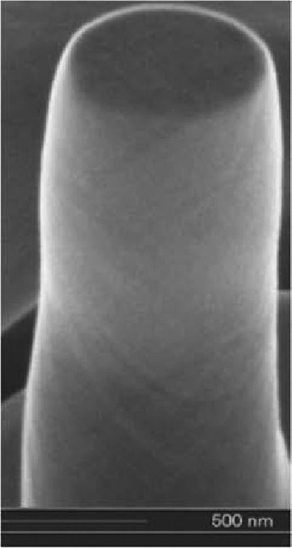
Scanning electron micrograph of compressed <001> gold pillar (initially 300 nm in diameter; scale bar is 500 nm), with visible slip planes of at least three apparent orientations indicative of homogeneous shape change induced by strain, exhibits compressive strength of 800 MPa, a roughly 50-fold increase over bulk gold.9 Reprinted with permission. ©2010 Elsevier
As in many fields, the rate of publication of refereed and adjudicated works related to the mechanical behaviour of nanomaterials is increasing at such a rate as to make exhaustive review a practical impossibility. A few hasty word searches across several of the more comprehensive databases such as Chemical Abstracts Service’s SciFinder, ISI’s Web of Knowledge, Elsevier’s Compendex and SciVerse ScienceDirect resulted in over 40 000 references through 2011, using terms like nanomechanics and nanomaterials combined with mechanics, mechanical properties, strength and the like. Several hours of sorting and limiting the list to the past 5 years still returns more than 9000 unique items with well over 200 self-described reviews since 2001. Even though a majority of these references are not directly pertinent to the present review, a thorough screening of such a large set becomes irrelevant before a useful summary could be disseminated; for example, the authors herein skimmed, scanned or read in their entirety approximately 800 papers in preparing this review and reduced that number to the present bibliography having substantial relevance. Original plans to plot publication/citation trends over recent years by major categories pertinent to mechanical property measurements of nanostructured materials finally resolved into being both misguided and superfluous, though this may be more beneficial in particular niche areas of focused interest.
Therefore, underlying the main goal of reviewing measurements of elasticity, hardness, toughness, strength and deformation on nanostructured materials is a motivation to cover a broad range of material and system types that are not often collected into a single article, focusing on more recent reports. Much of the review work has already been done that sufficiently covers nanomechanics from its beginnings to date and delves much deeper into the details as needed for distinct focus areas.1,4,5,7 – 11 In particular, the present review will avoid all but mere reference to nanotribology – the study of friction and wear at the nanoscale – as well as mention only within specific inevitable contexts particular details of nanoindentation studies and developments, whereas both topics have been covered in depth with expert detail by Bhushan and Palacio.12 Furthermore, many other nanostructured materials and system types are entirely left out of this discussion because their main applications are not directly concerned with mechanical properties; nanobubbles and confined liquids such as thin fluid films, nanofoams and nanoemulsions13, 14 define classes of viscous materials substantively different from those considered herein that, unlike fluids, can sustain static resistance to mechanical stress.
Background
Many of the differences in mechanical behaviour – and often in direct correlation to chemical, electrical and other property changes – of nanostructured materials with regard to their so-called bulk or even microstructured counterparts are caused by surface or interface (the more general term) stresses and interfacial energies.4, 11, 15, 16 Though the impacts of interfacial phenomena on colloidal and related materials (such as thin films and foams, many of which are also nanostructured materials) and their behaviours have been studied for more than 100 years in fluid systems,13 colloids dispersed in solid media are a greater challenge – not only the traditional particle–matrix types and not limited solely to nanoscale structures. Many solid–solid mixtures containing nanostructured materials may also be classified as types of colloids or as having some key traits in common with colloidal materials due to the significant influence of interfacial properties, such as mobility from thermal effects, negligible impact of gravity, adhesion effects being significant and size-scale effects on thermodynamic properties.17 – 19 Thus, the defining characteristics of colloidal materials and their ilk are applicable to nanoparticles of all shapes, nanofibres, nanocomposites, macromolecules in solutions or dispersions, thin films (though not classically considered a colloid) and even solid–solid suspensions, which include some metals, ceramics, polymers and other condensed matter with substantial volume fractions of nanoscale inhomogeneities.4 The colloidal classification is very broad and includes a need for understanding solid nanomechanics in particular cases. However, with any interdisciplinary work, it is important to recognise the potential both for discovering knowledge hidden by a non-traditional label and for possible rediscoveries of fundamental phenomena across disparate fields. The understanding of solid nanomechanics has lagged behind that of other nanomaterial systems due to measurement challenges for characterisation as well as a greater degree of difficulty in modelling practical morphologies under stress and strain for material response to uncover mechanisms of deformation and failure. There are distinct differences and difficult nuances across the overlapping disciplines of surface science, colloids, nanomaterials and the like that deal with crystal structures, defects, elastic mismatch, etc., and the scale-dependent nature of material properties of which all investigators are encouraged to consider with perspicuity for improved understanding.
There are obvious needs for fundamental scaling laws, where feasible, in science and technology that would ideally include a generalised formulation adequate for both micro- and nanomechanical regimes,4 the two having explicit distinction of scale not always adhered to in the literature. One underlying assumption of most scaling laws is a continuum approach where only mean-field structure–property behaviour is explicit; however, the fundamental nature of some scale-dependent phenomena or properties is, or may be discovered to be, stochastic and/or quantum, especially for nanomaterials; here, even the idea of a scaling law may be too incongruent for any utility. Apart from these distinctive candidates, accurate scaling laws for many properties may require more complexity of form than a single and classic size-dependent term, especially for hierarchically structured materials,20 of which biological constructs are particularly interesting (e.g. Fig. 2). Shape and distribution factors are other likely modifications for the more finely tuned relationships. Some experimental and simulation results on elasticity4 show good agreement with first-order scaling for the so-called two-dimensional (2D) and one-dimensional (1D) objects, namely nanoplates or thin films and nanowires, nanobeams or nanofibres respectively, being contracted to the nanoscale in either a single direction (2D object) or in two orthonormal directions (1D object). Nanoparticle melting is the classic example of a precise scaling law, though not describing a mechanical property, which describes interfacial effects that are also a contributing factor to nanoelasticity scaling behaviour, where the intrinsic length scale is of the order of lattice constants for metals (0·01–0·1 nm), of reptation or segment lengths for polymers, etc. Developing a widely applicable scaling law for elasticity in nanostructured materials remains challenging.
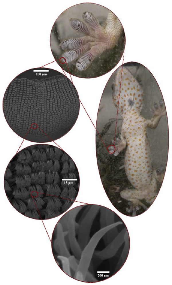
Photographs of the hierarchical biostructure in gecko (right) foot (top) revealing the well-known mechanism for incredible van der Waals adhesion with smooth surfaces. Scanning electron micrographs reveal the microstructure of its setae bundles (descending on left; scale bar 100 μm) and individual setae (scale bar 15 μm) splitting into terminal spatula ∼100 nm at the ends (scale bar 200 nm).257 Reprinted with permission. ©2011 Elsevier
The prospect of scaling law development for nanoplasticity21 – 23 would seem an even greater challenge, where the complex multiscale, time-dependent, path-dependent and thus irreversible processes of structural rearrangement are compounded. McDowell24 touches on plasticity in nanostructured materials, summarising the study of their inelastic behaviour as ‘a rich new topic’ where classical understanding seems to break down. Because nanoscale volumes of high stress can be prevalent and preexisting in nanomaterials by virtue of the grain size – as opposed to being nucleated in bulk or micromaterials having no intrinsic nanoscale before testing, aging, fatigue or failure – one may expect the pathways for plasticity and their probabilities to differ from virgin material structures that are homogenous at the 1–100 nm level. Furthermore, it is an unfortunate coincidence that the nanoscale is generally within the so-called ‘handshake’ regime between atomistic and continuum models, which makes any rigorous simulation and understanding of multiscale phenomena extremely onerous if not untenable with current strategies and capabilities.25 Thus, it is not surprising that a significant increase in this concerted research area has occurred only in the past 10–15 years, and primarily for metals, even though size effects on plastic deformation have been studied for many decades.7, 8
Of particular note are the differing plastic deformation mechanisms seen in so-called nano-grained metallic thin films – including grain rotation and sliding – and in ultrafine-grained metal alloys – involving multiple shear band formations – compared with materials with larger grain sizes where dislocations and work hardening are usually dominant.26 As yet, the damage initiation step from heterogeneous deformation to the flaw itself remains the critical unknown, even for single-phase metals. The obvious connection to grain boundaries as stress concentrating zones has not yet developed into a rigorous, causal formulation based on crystal and boundary orientations, stress–strain history and active deformation modes in the vicinity of an interface/interphase that will become damaged as well as those that do not. The problem is daunting for either experiment or simulation, continuing from a vast body of literature on damage nucleation.27
The motivation is clear for evolving the fundamental understanding of plasticity to include a more robust framework for damage nucleation with the fatigue-to-fracture/failure pathways in nanostructured as well as other materials. Relatively little has been carefully investigated concerning the physical process of fracture initiation directly (namely flaw nucleation), especially regarding grain boundary quality and means of quantifying slip transfer and heterogeneous deformation.27 The main difficulty would appear to be making a phenomenological shift for flaw nucleation away from the need for preexisting flaws (e.g. cracks, voids, etc.) or relying on a statistical basis for modelling or predicting material behaviour. Arguably, experiments on completely defect-free materials are seldom, if ever, encountered in practical engineering applications, but neither will all local failures originate from flaws in materials as formed, before testing or other designed use.
With significant questions remaining even for micromechanical behaviour, a complete and universal multiscale approach to our collective understanding will be a massive endeavour even if restricted to the simpler cases, e.g. crystalline matter.3, 7, 28, 29 Most frameworks will likely include both atomistic and continuum descriptions of mechanical stress–strain relationships across three or more length scales – molecular, mesoscale/handshake regime and macroscopic – for comparison with measurable systems; graphene is a primary example in a class of potentially defect-free extended materials other than single crystals that exhibit new challenges.30 A robust set of length-scale-dependence laws on mechanical properties will very likely enfold differing dominant mechanisms for overlapping classes of nanomaterials, whether metal, ceramic,31 polymer32, 33 or the various composites thereof,34 – 39 segregated by morphological families – fibres,40 films,41 particles,42 etc. Across the spectrum, it is the interfacial phenomena (e.g. grain boundary behaviour, interfacial stress and energy) that individually or collectively concentrate within a material to make a significant impact on macroscopic properties, whether lowering glass transition temperatures in polymeric nanoparticles, increasing crystallinity in nanofibres, blocking fracture propagation in metals and ceramics or acting as stress concentrators in composites. Whatever the mechanical property of interest, careful experimentation combined with accurate modelling becomes a deceptively basic mantra for nanomechanics that should encourage the curious but discourage the unwary or hasty investigators.
One-dimensional nanowires, nanotubes and other nanostructures
Starting with the outbreak of awareness of the existence of carbon nanotubes (CNTs) in the broad scientific community, 43 43,44 there has been a rapid expansion in the fabrication and characterisation of other 1D nanomaterials such as nanowires, nanopillars (Fig. 1), nanowhiskers and nanofibres.45 The existing body of experimental work in this field focused on mechanical properties and processes is much smaller than the same for model and simulation-based theoretical work. This is due to various experimental difficulties discussed below and followed by a review of work done with 1D zinc oxide (ZnO) nanomaterials during the past 10 years, perhaps the second most-studied species compared with CNTs based on the level of attention attracted from investigators. Despite the relative homogeneity of ZnO, the spectra of results from studies on its 1D nanomaterial forms (mostly focused on the Young’s or elastic modulus) are indicative of the challenges in achieving accurate consensus with regard to their mechanical behaviour. Both CNTs and ZnO nanowires will be considered in further detail in later separate sections. The range of findings for these two better-studied nanomaterials is a likely predictor for a continuing trend when others are investigated with commensurate intensity.
Measurement challenges and complications
Direct measurement of 1D nanomechanical properties remains challenging primarily due to the obvious difficulty in controlled manipulation. The model-based interpretation of experimental data and the lack of fabrication control of the structure of test specimens (phase, geometry, orientation, dislocations and defects) cast ambiguity into any conclusion made about mechanical performance and mechanistic explanation of this class of materials. Furthermore, the variety of testing methods (axial, bending, resonance and indentation) can yield different results for a single material property, such as elastic modulus, casting doubt as to the fabrication and design specifications for nanomaterial implementation for a particular application. Some successes in the attempt to elucidate relevant processes and factors have been realised by the execution of in situ TEM and SEM experiments for mechanical characterisation.
Modelling has also been used to evaluate the significance of various confounding factors. Molecular dynamics was used to evaluate contributions made by the presence of a native oxide layer and by surface defects in silicon cantilevers to the reduction in their apparent elastic modulus as their thickness decreases.46 The results indicated that the average elastic modulus decreased linearly with increasing defect volume, which is in agreement with analytical predictions and that a 30% loss in the apparent elastic modulus can be attributed to the inflation of the diameter of a nanowire due to the build-up on an oxide layer on wires with diameters near 100 nm. Recently, a critical correction was made to a form of the Young–Laplace equation that had been previously applied to compute nanowire elasticity from data collected in both static bending and in resonant frequency experiments.47 The correction incorporates initial nanowire stresses due to relaxation into the Euler–Bernoulli beam equation. This improvement removed the erroneous predictions by the earlier Young–Laplace approaches – that hardening occurs in small diameter (d<250 nm) SiNx nanowires when excited at their second resonant frequency, when softening actually occurs and the resonant frequency (and thus elastic modulus) decreases with cross-sectional area for beams with a combination of fixed and free boundary conditions at either supported end.
Atomic force microscopy (AFM), while a common and very useful method for small-scale mechanical measurements, has its own set of experimental complications. Sample deformation due to adhesion forces between the test object and an AFM probe tip has been evaluated using the Johnson–Kendall–Roberts model backed up by finite element (FE) analysis.48 The results showed that failure to account for this extrinsic factor could lead to an underestimation of the elastic modulus of a nanowire by as much as 40%. It was also shown that this effect is more pronounced as nanowire diameter increases, leading to an apparent increase in elastic modulus as diameter diminishes49 that may not be applicable for interpretations of true nanomaterial stiffness, hardness, toughness and mechanical performance in general. This demonstrates the significance of uncertainty in AFM measurements for elastic modulus and work of adhesion. Uncertainty introduced through unknown or non-linear AFM photodiode sensitivity was the dominant contributor in measurements where the magnitude of the total uncertainty in deflection and/or force approached that of the results of statistical sampling randomness.
Typically, the assumed anchoring mechanism between a test sample and its platform – being either fixed/clamped or simple/free-bending – is also a potential cause for inaccuracies in AFM-based results. In most studies, it is assumed that sample-to-platform attachment is rigid, which would lead to an under-estimation of sample strength and elasticity since some deformation will be caused by finite elasticity in the anchoring mechanism. To provide data for determining or correcting this assumption, the use of multi-point measurements was first demonstrated by our research group on suspended polymer nanowires50 undergoing three-point bending tests, followed by reports on nanowires of silver51 and gallium nitride (GaN)52 where the stiffness profile versus loading position relative to the supported ends is used to interpret boundary conditions for the Euler–Bernoulli beam model, as well as for ZnO nanobelts.53
A much more detailed analysis was undertaken recently where the Winkler model is used to simulate deflections between a loaded nanowire attached to an elastic substrate and incorporated into the Euler–Bernoulli equation to make corrections to the computation of the elastic modulus of the nanowire.54 Another study approaching this same fundamental measurement problem evaluated the clamping force available both from deposits by electron beam-induced deposition (EBID) and by van der Waals forces between a tungsten probe and a silicon nanowire.55 This study found that a multiplying effect on shear strength from relative humidity impact on capillary effects can be several hundred per cent. The elasticity of the EBID material was found to be ∼35 GPa, which is similar in magnitude to the elasticity of many nanomaterials under test, raising the distinct possibility that strain measurements are too high leading to understatement of material strength and rigidity. A statistical approach56 was demonstrated to remove bias and artefacts due to uncertain boundary conditions, instrument instability and experimental environment from deflection profiles of a ZnO nanowire subject to three-point bending tests. The application of this method resulted in an upward correction of 7% in the elastic modulus.
Another less common configuration for nanomechanical testing than the suspended nanowire is a hoop pinching or squeezing of a closed ring, with the most current example being the so-called ‘nanoring’ that is of the order of 10 μm in radius made of nearly single-crystal copper.57 The structure is believed to be curled out of a straight and fattened wire more than 200 nm wide but roughly one-tenth that in thickness via a growth-stress induced bending mechanism. When pinched with micromanipulators, the copper rings can sustain fully elastic strains of a few per cent and much higher stresses than the bulk yield strength of copper would allow. This particular technique, while seeming to suit nanomaterials of the hoop or ring geometry only, is a good example of a more complicated measurement than a simple straight nanowire over a trench, for instance.
Atomistic simulations of nanocrystalline nickel nanowires indicate that plastic deformation by nanoindentation is more likely determined by the grain size within the structure and grain boundary sliding than by the nanowire diameter, directly affecting behaviour by some solid surface energy or available free surface contribution.58 However, a smaller diameter gives a larger surface-to-volume ratio that makes the grain boundary deformation more facile in tension (Fig. 3). Therefore, it is clear how beam-bending type experiments with nanowires using AFM can reveal both stiffening and weakening trends with diameter depending on morphology, which is not often known for the particular material samples under test.
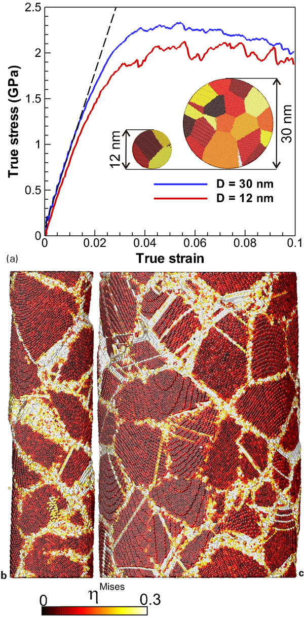
Visualisation of MD simulations for nanocrystalline nickel nanowires showing a true stress–true strain behaviours for tensile deformations. Reconstructed nanowire morphologies at 10% strain for b 12 nm and c 30 nm (higher stress curve) diameter nanowires having mean grain size of 7 nm. Shading indicates that local plastic deformation is higher (lighter) at grain boundaries from sliding than inside grains (darker) from lattice dislocations.58 Reprinted with permission. ©2010 Elsevier
To better understand the nature of nanowire mechanics, continuum models for interpreting results will need a consistent approach to address initial surface stresses, which many studies have ignored, in a complete solid surface energy model including the more typical interfacial tension and elasticity.47, 59 Song et al. argue that full consideration of surface-induced stresses before nanowire bending or flexing (i.e. initial or residual stresses) provides better predictions or fitting of experimental results in ceramic (silicon nitride and ZnO) nanowires yet still fall short (elastic modulus too low) for metallic (fcc Ag and Au) nanowires. Curiously, they ignored key sets of data in their discussion.51, 60, 61 While FE and molecular simulation methods are obvious alternatives that have been used to account for surface effects, they remain difficult for the mesoscale where many nanowire studies and interests include larger diameters and longer working structures, especially for experimental corroboration in size-dependent studies of material properties like elasticity in metal and ceramic nanowires.
One very intriguing method designed to take better advantage of the potential for aligned CNTs towards higher reinforcement of composite materials begins with the very common process of electrospinning long, continuous polymer fibres,62 which are an order of magnitude or more larger than CNTs and thus much easier to handle in up-scaling for bulk manufacturing. By confining dispersed CNTs into the electrospun fibre of poly(vinyl alcohol) (PVA), the large aspect ratio (length-to-diameter) forces a coaxial alignment. Electrospinning is easily scalable, opening up many opportunities for multiscaled experiments on the mechanics of materials utilising controlled arrangements of CNT and other 1D nanomaterial fillers in parallel, woven or other alternating patterns feasible for preparation of micro- to ultrafine fibres and fibre mats.63 As is often the case, the polymer fibre–CNT compatibility (namely interfacial strength) becomes the limiting factor.
Wang et al. measured the single PVA–CNT shell–core compound fibre with AFM in the traditional three-point bend test at the mid-point for deflection with presumed fixed or clamped ends. In general, the mechanical performance of core–shell nanofibres or nanowires – a natural next step in the evolution of modified nanomaterials development – appears relatively unknown. Most 1D core–shell nanomaterials have been ceramic.64, 65 Some work on the nucleation of dislocations and strain relaxation has been done on lattice-mismatched semiconductor nanowires.66 This very brief review reports a consistent pattern of significantly higher elastic strain limit for core–shell nanowires than for their planar interface analogues. Adding to the already-described difficulty of not having direct confirmation of the exact boundary conditions of a given nanowire or nanofibre under test, most investigators do not have access to AFM–TEM systems that would facilitate knowing the precise core–shell morphology or the CNT alignment(s) and length(s) within a tested compound fibre. Potential strength enhancement from the buried interface of the core–shell is particularly high for polymer coatings/shells where macromolecular alignment to a core structure (e.g. CNT) during fabrication requires further experimental corroboration, especially in the PVA–CNT system where there is an unknown contribution of using the surfactant to disperse the CNTs.
Other bending studies of suspended PVA nanofibres suggested a strong increase in effective Young’s modulus.67 The results were also based on AFM measurements and the Euler–Bernoulli model with the assumption of fixed conditions at both ends of the suspended fibres. The diameter of the smaller nanofibres had been reduced by air plasma treatment. There was a 10-fold increase in the elastic modulus as the diameter dropped from 100 to 20 nm. Systematic error with regard to fibre cross-section and enhanced cross-linking due to the air plasma treatment were suggested as explanations for the significant increase in the elastic constant. Since the plasma-treated fibres were elliptical with the major axis corresponding to the neutral bending axis, this would be expected to appear as an increase in bending stiffness compared with fibres of circular cross-section with the same average diameter.
Direct AFM tensile testing of PVA and other polymeric fibres of 100–200 nm diameters exhibited rather diverse behaviour68 as a strong indication that bending mechanics are much more accessible and feasible for the present. Microelectromechanical system (MEMS) designs were recently used to evaluate tensile failure stress and strain of a nickel nanowire69 and for stretching a 50-nm silicon contact in TEM.70 The silicon was stretched from an initial length of a few nanometres to the final 50-nm distance, demonstrating a level of plasticity much greater than that of bulk silicon. Two mechanisms were proposed to contribute to this observation based on qualitative TEM image analysis and molecular dynamics (MD) simulation. The first was diffusion of silicon into the contacts from the adjacent material; the second was attributed to migration of atoms from crystalline grains into the amorphous phase surrounding those grains. The diameter of the contact was observed to contract until it matched the size of the grains, at which point necking occurred in the intervening amorphous regions, initiating a distinctive second stage in the stress–strain curve. These examples demonstrate that greater sophistication in tensile testing is required for significant understanding to be developed, such as with MEMS designs and improved in situ TEM where the complicated processes can be directly observed simultaneously and later modelled with a high degree of certainty between employed mechanical mechanisms and real physical behaviours.
Zinc oxide nanowires and nanobelts
Single-crystalline wurtzite ZnO nanowires and nanobelts have attracted a great deal of attention due to their piezoelectric and semiconducting properties. The numerous attempts to evaluate their mechanical properties (especially elastic modulus) have produced a great deal of conflicting information and demonstrate the confounding issues involved and attempts at explaining the causes behind the observations. A very early report of the elastic modulus of ZnO nanobelts used in situ alternating electric field to find the mechanical resonant frequencies inside a TEM (Fig. 4).71 Two modes of transverse vibration were observed in the rectangular cross-sectioned belts, and the elastic modulus based on classic elasticity theory gave eight results (four nanobelts with two modes each) that ranged from 38 to 65 GPa. This is significantly lower than the previously reported elastic modulus for bulk single-crystalline ZnO of 140 GPa.72 The cross-sectional dimensions of the wires ranged from 19 to 55 nm. Reported measurements through lateral AFM gave a result of 29±8 GPa on vertical, single-crystal ZnO nanowires grown in place by gold-catalysed the vapour–liquid–solid method, for an average nanowire diameter of 45 nm (range 30–60 nm).73 The range of individual measurements exceeded those experimental errors, with length and diameter both named as contributing factors.
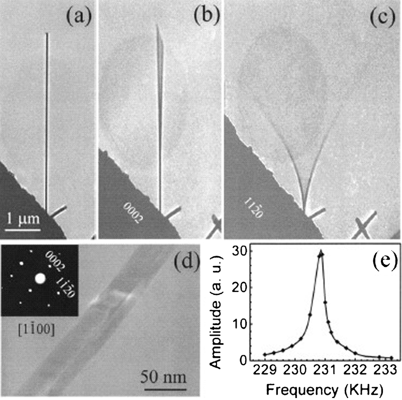
Images (TEM) of ZnO nanobelt.71 Reprinted with permission. ©2003 American Institute of Physics
Span-length deflection profiles of ZnO nanobelts undergoing three-point bending tests by AFM were used with the Euler beam model and simple boundary conditions to determine the elastic modulus of three nanobelts.53 The results varied from 100 to 170 GPa; the higher value was taken from the thinnest test specimen. A significant level of surface roughness was noted and compensated for by ‘normalisation’ through the subtraction of the deflections measured with a low-force pass along the length of the nanowires. Further statistical refinement on the same data was later performed56 to arrive at corrected results for the elastic modulus about 10% higher than without correction. No size dependence was observed in similar tests on ZnO nanobelts that ranged from 50 to 140 nm in thickness based on mid-point deflection and fixed-beam boundary conditions.74 The results for the elastic modulus were much lower than bulk, ranging from 32 to 57 GPa despite the fact that apparent deflection was corrected by subtracting out an experimentally based estimation of tip-sample indentation. Further testing by AFM indentation in the same study resulted in an elastic modulus of 31 GPa. This was accompanied by a significant amount of creep, attributed to the relatively large number of atoms at the surface with low-coordination number available to facilitate the generation and motion of dislocations.
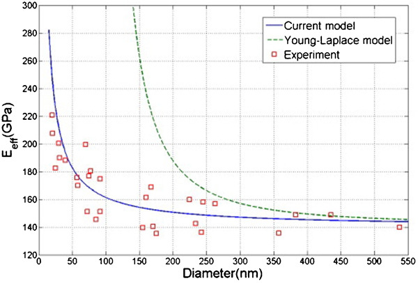
An increase in elastic modulus of 50% over bulk was observed in ZnO nanowires as their diameters decreased from 500 to 20 nm (Fig. 5).64 These nanowires were fabricated by a thermal evaporation procedure and tested using an electric-field-induced resonance method. This measured increase in rigidity was attributed to decreased bond lengths at the surface of the nanowires. However, the data suggest two modes of enhancement in the elastic modulus that were not identified by the authors: one resonance mode shows an enhanced elastic modulus gradually increasing with diameter below 500 nm while the other mode diverges rapidly for diameters below 100 nm. This perhaps is due to asymmetry in cross-section or anisotropy in the crystalline material. Five years later, another group of investigators incorporated initial relaxation stresses into the Euler–Bernoulli beam model and matched the previous data (Fig. 6).47
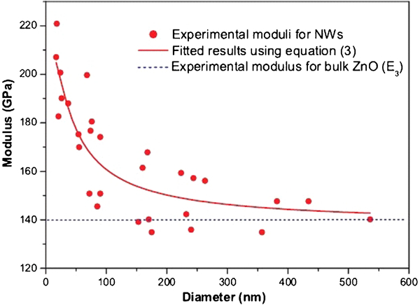
Suspected diameter dependence in measured elastic modulus for [0001] oriented ZnO nanowires in bending mode fitted with a simple core–shell model (solid line) compared against bulk ZnO modulus (dotted line).64 Reprinted with permission. ©2006 American Physical Society
Indentation tests on ZnO nanobelts by AFM showed a strong dependence on width to thickness ratios for the elastic modulus, which ranged from 10 GPa for the wide specimens (width-to-thickness ratios ∼10) to 100 GPa for the narrow ones.75 The thickness of the nanowires ranged from 20 to 230 nm. This trend was explained by planar defects dependent on growth direction relative to crystal structure after surface effects and phase transitions were rejected as possible causes. But in the same year, a core–shell model was used to explain Young’s modulus values taken from another AFM indentation study that also showed an increasing trend, this time from 100 to 200 GPa as ZnO nanowire diameters dropped from 134 to 26 nm.65
The first purely tensile measurements on ZnO nanowires were reported from experiments with an in situ MEMS device for an elastic modulus of only 21 GPa based on three nanowires (diameters: 217, 287 and 314 nm) and with a larger set of nanowires on a piezoelectric strain substrate to show an increase in fracture strain from 5 to 15% as diameters shrunk from 470 to 220 nm.76 Higher atomic binding energies were used to explain the observation. These results were shortly followed by a report where energy-based modelling of ZnO nanowires under tensile load indicated that a phase transition from wurtzite to graphitic takes place.77 The recoverable strain rate reached a maximum of 16% and was matched by MD simulations. A similar in situ study with TEM followed, where the resulting measurements indicated that the elastic modulus began to exceed bulk once the nanowire diameters dropped below 50 nm.78 Further confirmation was given in the same report by MD simulations for ZnO nanowires with diameters less than 20 nm to extend the experimental data. Inspection of these numerical results confirmed that enhanced elasticity likely existed at the surface due to bond relaxation and long-range interactions.
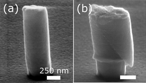
A more recent publication disseminated in situ TEM–AFM measurements of compressive forces on buckled ZnO nanowires with diameters ranging from 110 to 40 nm.79 The Euler buckling formula was used to evaluate the elastic modulus, with decreasing diameters, from 180 to 250 GPa. A separate set of nanowires with diameters over 200 nm were tested as cantilevers, and the Euler beam formula-based results for the elastic modulus were close to that of bulk ZnO. Surface relaxation and long-range interactions were again credited for the observation. A higher degree of flexibility, which coincided with a transition to an amorphous phase as noted by TEM imaging, was observed in the thinner wires and attributed to the greater degree of freedom for surface atom relocation. A graphical summary of the collective experimental results on ZnO nanowire/nanobelt (nb) elastic moduli (Fig. 7)53,64,65,71,73 – 76,78,79 suggests no clear dependence on the method of measurement, though most nanowire studies show a significant stiffening effect for the smallest diameters while most nanobelt data fall well below the expected bulk modulus. The statistical connection argues for a geometry effect, though it is more likely that the resultant morphologies from nanowire syntheses differ substantially from those of nanobelts, whose basic growth mechanism including probabilities for defect types and densities produces weaker structures overall.
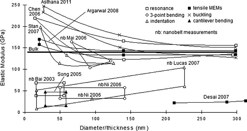
Experimental results for the elastic modulus of wurtzite ZnO nanowires and nanobelts (nb)
Other resonance measurements
Resonance, near-resonance and off-resonance oscillatory mechanical measurements are somewhat less common for nanoscale materials than might be expected in comparison with the macroscale. However, there is strong basis in theory and practice that oscillatory experiments provide more robust and sensitive means for testing nanostructural mechanics. In addition to the above-mentioned ZnO measurements, an example of laser Doppler vibrometry showed the frequency response of thermally excited high-aspect Ag2Ga nanowires.80 The results agreed well with Euler–Bernoulli beam theory and indicated an elastic modulus of 84·4±0·6 GPa. These nanowires showed superior characteristics in comparison with multi-walled (MW) CNTs and silicon cantilevers for mass sensing applications with sensitivity levels down to the femtogram level. Another illustration of the use of frequency response for mechanical study can be seen in a recent publication on wurtzite GaN nanowires coated by atomic layer deposition.81 A substrate with many grown-in-place nanowires was placed on a piezoelectric actuator for electron microscopy. Deposits of a layer of alumina, ruthenium and platinum were tested on nanowires of 50–200 nm diameters, and it was found that an upward shift in resonant frequency (a few kHz per nm of thickness) occurred whenever the deposits formed conformal layers indicating enhanced nanowire stiffness. A 10-fold decrease in quality factor was observed for layers 4 nm in thickness. The resonance frequency sensitivity of bare GaN nanowires to mass loading was large enough to detect deposits of tens of picograms, corresponding with a single atomic layer deposition cycle. No insight into material mechanics was given other than frequency response measurements being consistent with previous measurements for elastic modulus of the material in the deposited layers.
Compression tests on nanopillars
Compression tests on nanopillars, and truly in most cases submicrometre-diameter pillars, fabricated by focused ion beam techniques have been carried out in many recent investigations, providing insight into the size dependence of deformation mechanisms and their associated stresses.22,82 – 96 Their collective scope is extensive with many examples on metallic structures illustrating a relative dearth in other materials tested.
Three aspect ratio-dependent mechanisms were observed for Al nanopillars: shear band activation for large diameter pillars (900 nm), localised slip and bulging at the top for the intermediate pillars and buckling for the small diameter pillar (250 nm).82 Similar testing on bcc Mo micropillars (200–5000 nm) still demonstrated the scaling effect, where yield stress increased by over a factor of 3.83 Further discussion was given on how crystal structure (bcc and fcc) and orientation affect the movement, elimination and interaction of dislocations. Other dislocation dynamics simulations suggested that the scale dependence in fcc crystal structures is more pronounced due to more efficient dislocation extinction.84 Compression tests on Ni pillars of diameters between 150 and 2000 nm showed similar improvements in critical resolved shear stress along with increased strain hardening rates with decreasing diameter.85 Discussion of complicating effects associated with pillar fabrication and testing method were also given.
Dislocation processes were observed during compression and bending tests on Cu-based and Zr-based metallic glass nanopillars.86 Shear band formation was the dominant mechanism for deformation in both bending and compression experiments, while deformation was more or less homogenous in the bending tests. The predominant diameter-dependent observations in the compression tests were the frequency and magnitude of sudden bursts of shear displacement. Small pillars had more frequent and small bursts along with lower strain rates suggesting that shear band propagation is suppressed as material dimensions are reduced.
Compression tests on electroplated bismuth nanopillars used SEM and TEM to discern deformation mechanism dependence on diameter.87 It was found that as the diameter dropped below the grain size, defect gliding within grains took the place of grain boundary-mediated processes in determining plastic behaviour of the pillars. This effect, along with the reduction in the size of surface defects, was credited for the observed increase in flow stress for the smaller pillars along with a loss of sensitivity to strain rate. A similar study was conducted by the same investigators on tin nanopillars fabricated in the same way as the bismuth nanopillars (Fig. 8).88 X-ray diffraction was used instead of TEM. No rate dependence was discovered in this case, but strength enhancement with diameter reduction was again observed. Annihilation of dislocations at the nanopillar surface was proposed as the strengthening mechanism. One unique discovery in that study was that the sensitivity rate of flow stress to pillar diameter matched that of an fcc structure, even though the tin structures were bcc.
Images (SEM) of a original crystalline tin pillar (∼560 nm diameter) and b compressed beyond failure show shear slipping and extrusion (wrinkling or bulging sidewalls).88 Reprinted with permission. ©2011 Elsevier
The most obvious outlook for nanopillar compression and other modes of mechanical testing is a future expansion to cover non-metallic structures, which perhaps have increasing challenges from fabrication to measurement to modelling difficulties due to their variety in range of physical characteristics.
Nanolines
The term ‘nanoline’ (or even nanoribbon) might be more geometrically accurate than ‘nanowire’ for those 1D nanostructures anchored over their entire length or simply fabricated in place on the substrate using lithography techniques. One mechanical measurement method uses the buckling amplitude and wavelength of a fully supported nanowire adhered to a compliant, pre-strained substrate, which is then allowed to relax to produce the buckling. Energy-based continuum modelling can then be used to compute the elastic modulus.97, 98 One clear disadvantage of this approach is that the elastic modulus is used as a fitting parameter to theoretical predictions of the radius-dependent buckling wavelength and/or amplitude. This prevents clear determination of any scale dependence in the elastic modulus.
A more novel technique to ascertain Young’s modulus uses FE analysis of Brillouin light-scattering spectra taken from poly(methyl methacrylate) nanolines fabricated by lithography and plasma etching.99 Results indicated a decrease in elastic modulus of about 10% relative to bulk for nanolines with a height of about 125 nm and a width of 53 nm, which was consistent with previous measurements made on thin films. One advantage that this method has over static buckling measurements is the freedom from interference of plastic and viscoelastic processes. While the descriptive knowledge gained from 1D nanoline mechanical measurements outlined above is not clear in translation to formulate a generalised understanding of nanowire behaviour, it provides an alternative geometry for measurement that could be easier and perhaps more reliable than the more common cantilevered or suspended techniques discussed earlier.
Carbon nanotubes
After crystalline metals, CNTs of various morphologies may be the second most-widely studied type of material for nanomechanical properties – certainly one of the most rapidly-growing interests in nanostructured materials.100 It is important to note that the discoveries of single-walled (SW) CNTs as reported in the early 1990s came 40 years after the first report of hollow carbon fibres of nanoscale that could rightly be called MWCNTs today.44 Both SWCNTs and MWCNTs of different lengths, diameters and chirality have been studied as isolated members,101 interacting individually with a localised environment62 and as filler in extended composite materials.102 Arguably the most challenging measurements are of the first and second kinds, where direct access to single CNTs, or small well-defined set configurations, is possible. Aligned arrays of vertical MWCNTs called films, mats, forests, carpets, turfs and foams are more practical constructs in current system designs where they may act as compressive energy absorbers, among other qualities, on the microscale.103 – 106 The network mode of mechanical deformation is via coordinated buckling – bending into loops as opposed to the short-range shell buckling – with a period of the order of 10 μm that initiates from the growth end and piles up as a propagating strain wave into permanent kinks (Fig. 9).

Images (SEM) of vertically aligned MWCNT arrays or brushes ∼1 mm tall after compressive buckling occurred at the growth-substrate end. a buckled/wrinkled end and b straight midsection magnified to 10 μm scale bar, and c buckled and d straight sections magnified to 5 μm scale bar.105 Reprinted with permission. ©2011 Elsevier
A substantial review in 2011 of CNT mechanical testing and electron microscopy is a convenient resource and detailed example of the necessary, tedious and expensive research required – even for nanostructures as well-defined as fullerenes – to make significant advances in quantitative understanding of nanomaterial properties and behaviour.101 In order to connect theoretical modelling to reality with some rigor, the exact morphological conditions of a specimen are needed, such as from high resolution TEM in situ mechanical measurements. With CNTs, this has established shell and tube buckling (Fig. 10), fracture and interlayer sliding governed by van der Waals interactions.107 – 109 Another very important aspect to nanomechanical testing of supported nanostructures is the determination of substrate interaction during the measurement, which has been recently developed in a straightforward fashion for CNTs and carbon nanocones in dense and patterned ensembles via a nanoscratch technique to quantify adhesion.110 Raman spectroscopy has also been used to evaluate the level of perfection of the hexagonal structure in MWCNTs, among many other graphene-related uses, where the elastic modulus of cantilevered CNTs was then evaluated through resonance frequency.111 Defects in the graphene structure were believed to reduce the elastic modulus by a factor of 3.
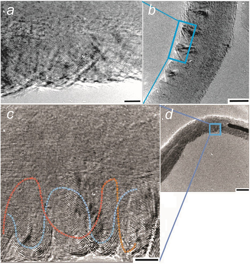
Images (TEM) of buckling in bent MWCNTs. a Magnification of sidewall wrinkles (5 nm scale bar) inside the shallow bend of micrograph b with 20 nm scale. c Magnification of wrinkles (5 nm scale) inside the sharper bend of micrograph d with 20 nm scale. Graphene layers within the nanotubes are obvious in some sections at the higher resolutions of a, c.107 Adapted with permission. ©2011 Elsevier
The previously mentioned electrospinning method for isolating and studying the fundamental interactions of single CNTs in a PVA matrix62 produces a compound fibre for mechanical testing with AFM or in situ TEM107 to investigate strength and failure mechanisms. Wang et al. estimated Young’s modulus from three-point bend tests to be of the order of 10 GPa, or 50% higher than their PVA fibres without CNTs, indicating high interfacial strength even with their use of surfactant to disperse the CNTs. In this case, the MWCNT cores are suspected of precipitating polymer crystallinity during fabrication as one source of increased fibre strength. Relevant to other nanowire bending studies, it should be noted that Withers and Aston112 considered the nanofibres as having fixed or clamped ends, an assumption which if not precisely accurate leads to an artificially large value of E. They further compared the strength of several polymer–CNT composites from other sources on a basis of effective Young’s modulus for the CNTs and several studies of isolated CNTs to demonstrate the general inability to capitalise fully on the well-established inherent ‘ultra-strength’ of CNTs with elastic moduli believed to be of the order of 1 TPa, if that concept indeed remains robust at the molecular level and the CNT is ideal (e.g. uniform, no defects, no residual stresses, no bends, etc.).100,113 – 117
Similar but far less-studied are boron nitride nanotubes (BNNTs), which can be more insulating than their CNT counterparts, exhibit electrical properties less sensitive to morphology, be more stable against thermal and chemical changes for potential use as NEMS components and composite filler alternatives.118, 119 One investigation used an AFM tip to compress a high-aspect ratio SWBNNTs to determine elastic moduli of roughly the same magnitude as what has been measured for some CNTs (∼1 TPa).118 A high degree of flexibility was also observed and additionally confirmed by in situ use of AFM–TEM to compress BNNTs, revealing pronounced buckling with reversible strain of up to 26%.119 Tensile and compressive tests were reported elsewhere on multi-walled BNNTs in pristine and in joined conditions where amorphous carbon was applied by EBID.120 The BNNTs were attached to a TEM grid at one end and bonded to an AFM tip at the other. It was found that the mechanical properties of the nanotubes were inferior to those of their CNT counterparts, but the BNNTs that had been welded with amorphous carbon did outperform other composite carbon structures.
A call for methodical study is perhaps nowhere stronger than for graphene-based moieties, where the collective knowledge-base might be updated in summative review once per year in order to keep pace with the surge in publications of various CNTs, carbon nanocoils121 (Fig. 11), graphene sheets, nanocones,110 doped fullerenes, CNT fibres, bundles and composites122, 123 in need of critical scrutiny. With graphene-based nanostructures, as much as with other nanomaterials, it remains uncertain how to determine accurately the impact of a single defect on intrinsic material properties due to the as-yet uncontrollable effect of electron damage during the measurement of plastic onset, dislocation or vacancy creation, and fracture. Even for tests as seemingly straightforward as the bending of a 3-nm thick graphene cantilever by AFM, the results for Young’s modulus are difficult to reconcile.124 A value of 37 GPa was computed using the interaction forces measured directly between the AFM probe tip and the cantilever based on the Derjaguin–Müller–Toporov model, whereas a much different result more representative of previous nanoscale graphene measurements (0·7 TPa) was found based on the force deflection curve of the cantilever through the Timoshenko beam-bending and shear model.
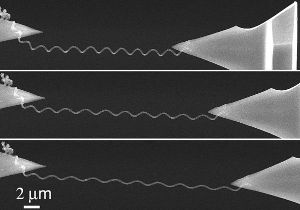
Electron micrographs of carbon nanocoil stretching in situ experiment. Both nanocoil ends are anchored to cantilevered probe tips for direct measurement of force with elongation.121 Adapted with permission. ©2003 American Chemical Society
Advances in modelling CNT behaviour are a general match to what quality experimental data exist but are yet insufficient to demonstrate strong confidence in the various continuum-to-atomistic strategies.125 SWCNT mechanics can be well described by an anisotropic shell model, which also suggests trends in chiral differences: buckling and tensile strength expected to be highest for armchair CNTs and lowest for zigzag with the chiral variants as intermediates.108 Compressive buckling has also been predicted in SWCNTs as a function of aspect ratios of length and diameter (Fig. 12)126 as well as post-buckling response, suggesting an off-long-axis twisting or hinging at the weaker flattened locations.127 Experimental measurements are still lacking for validation in detail.
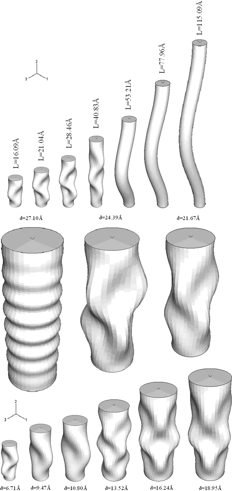
Buckling and bending modes predicted from shell modelling of axial compressive stress (top row) on SWCNTs (5,5 armchair) as a function of length at constant diameter (0·671 nm) and (middle and bottom row) on SWCNTs of various diameter at L/d = 3.126 Adapted with permission. ©2011 Elsevier
Torsional buckling via shell model and MD simulations support a van der Waals interaction between layers in shear for double-walled CNTs128 and MWCNTs129 that strengthens the nanomaterial. Earlier modelling efforts on MWCNTs via shell models towards torsional buckling with van der Waals interactions indicated interlayer slipping governed critical shear for thin-walled, large radii nanotubes, where the number of layers does not significantly impact behaviour.130 This finding implies a potential limitation as well as a convenience for most composite applications today and in the near future, since polydisperse MWCNTs are currently the most readily available and affordable for scale-up targeting feasible materials and technology development in the short-term. Saha and Maiti generally support this outcome for MWCNTs from 2–6 layers thick, with extensive results on triple-walled CNTs.129 TWCNTs were also tested in silico for buckling by axial compression and demonstrated a non-monotonic trend in buckling load with temperature131 similar to that computed for torsional buckling;129 that is, they found a maximum critical shear stress at room temperature likely connected with the inversion of thermal expansivity from low to high temperatures. This behaviour immediately raises concerns for stable material behaviour across large dynamic operating conditions, such as those experienced in air and space flight where strong, lightweight components are most desirable.
Molecular dynamics results for single defect impact on zigzag SWCNT axial strength matched reasonably well to historical data and other simulation approaches.116 The major significance to this type of study is the optimisation target for CNTs as composite fillers where increasing defects correlate with decreasing intrinsic nanotube strength but increasing matrix compatibility for a stronger interfacial strength. In this context, the model predictions of a decrease in compressive buckling strength when certain atoms or molecules diffuse into the hollow of a CNT could have important time-dependent ramifications on composite aging.117,132 – 134 The internal changes in intermolecular bonding could strengthen or weaken the CNT with respect to a particular mode of strain (e.g. Fig. 13), dependent on the loading fraction, constituent morphology and how they coordinate.
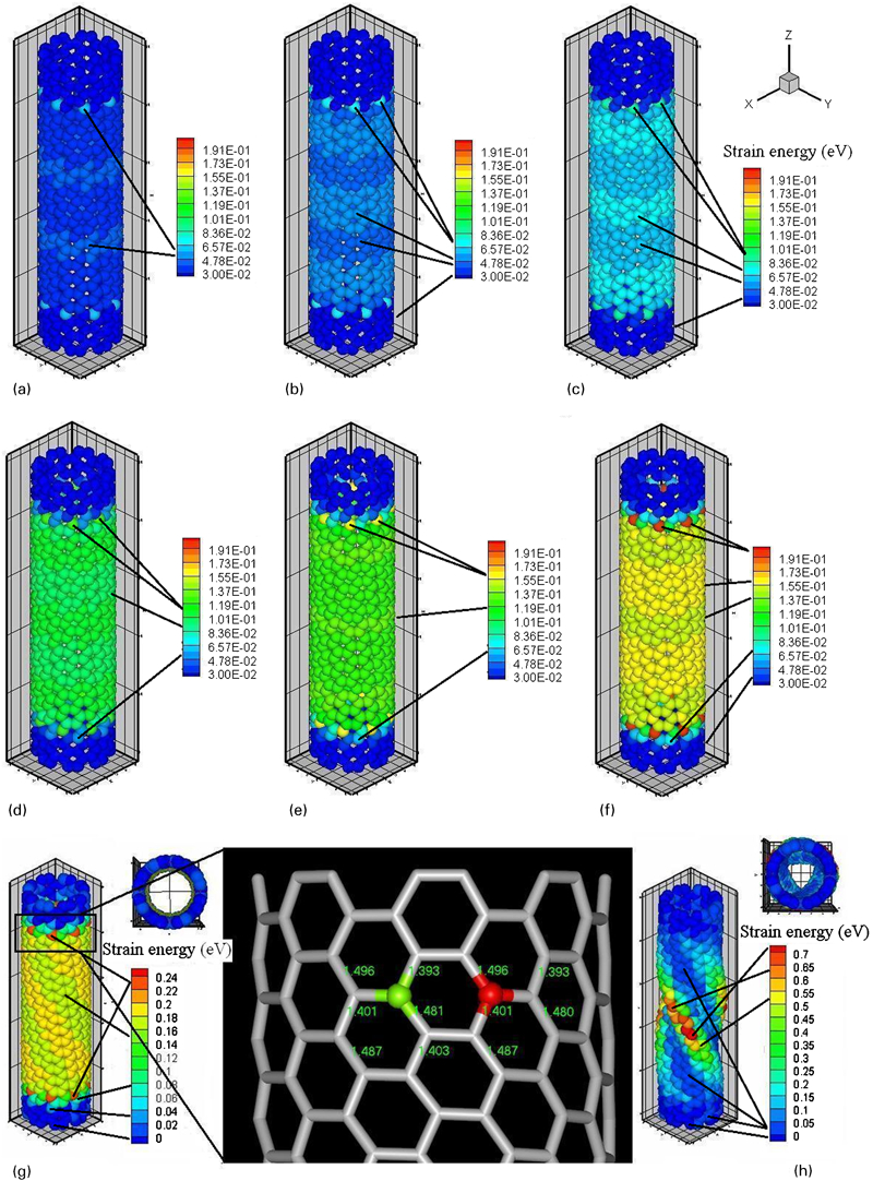
Strain energy simulation of armchair SWCNT (8,8) at torsional angles of a–h 12·5, 14·2, 16·5, 19·9, 22·2, 24·5, 25·1 and 25·6° illustrating wave-like behaviour of energy transfer up to spiral buckling (g and h).133 Adapted with permission. ©2011 Elsevier
Perfect, armchair SWCNT MD models of non-linear elasticity, tensile yielding and failure predict increasing activation energies for defect nucleation (namely the covalent carbon–carbon bond rupture) up to a plateau CNT radius of ∼2·4 nm,135 which would be expected based on residual bond stresses decreasing due to lower curvatures. Still other simulations indicate chiral and diameter dependence to axial tensile and compressive elasticity for both zigzag and armchair SWCNTs on modulus and Poisson’s ratio, suggesting that some smaller CNTs may be weaker than expected, which could have broad ramifications in practical composite formulation designs.136 Many modelling studies are lacking sufficient, or in some cases any, experimental data to validate their predictions, which would require in situ TEM-based mechanical studies or the like to what has been accomplished for nanostructured metals,89, 90 for example.
Extended nanostructures and nanocomposites
The context of this section alone deserves several extensive reviews separated into the mechanical behaviours and properties of: extended nanostructured materials, such as pure metals and single-component materials like pure ceramics and polymers not produced from combination with prefabricated nanomaterial fillers; thin films, coatings, multilayers and similar 2D manifolds; nanocomposites distinguished by particle–matrix, fibre–matrix, particle–particle, fibre–fibre, polymer blends and other primary mixtures. There is certainly justification for each to be published in the near term. The few examples considered herein must suffice to outline similarities and contrasts among the various nanomaterial types, which will hopefully generate enough focused interest for the relevant expert communities to donate their time towards thorough reviews and continuing concise, incremental updates with functional utility for their fellow investigators.
Nanocrystalline metals, ceramics and their nanocomposite structures have been studied across a vast array of specific cases. One cummulative result is the now almost common, and of course dangerously oversimplified, presumption that ‘smaller is better’ when it comes to increasing strength, hardness and/or toughness through grain size control, with a typical tradeoff being embrittlement. This perhaps stems from erroneously holding to a simple Hall–Petch descriptive framework ignoring the inverse or reverse effect(s) with shrinking grain size.7,25,137 – 140 Various studies indicate that a maximum strengthening occurs in the 10–30 nm range such that smaller is obviously not always better, even if all other materials parameters could be held constant, which is the likely crux of the matter. Scaling relationships are also affected by grain shape, relative orientation, volume fraction and spatial distribution in practice.9 After more than 30 years of study, there remains a lack of both computational and experimental design capabilities to address the mechanistic details adequately across the necessary length scales. Scaling laws with some significant element of empiricism are pragmatic for current investigations, but understanding the mechanisms from which the scale-dependent behaviours originate is of far greater interest and utility.
Among the array of proposed and observed mechanisms for deformation are grain boundary (GB) diffusion, stress-driven migration, and sliding, lattice dislocation slip, grain rotation and nanoscale twinning that are believed to be involved to effect toughness enhancement, most recently demonstrated in a three-fold increase in fracture toughness through cooperative GB sliding and migration near crack tips.141, 142 While several modes may exist for a given micro-/nanostructured material, it is likely that a particular combination of mechanisms with certain fine-tuned occurrences, perhaps even in true synergy, will create optimal conditions for mechanical behaviour. The focus of the following section brings attention to a particularly exciting and difficult family of nanostructured materials with great contemporary and future interests.
Single component nanostructures
Nanostructured metals are an intensely studied topic better addressed by other sources;21, 23, 86, 143 however, shape-memory alloys (SMAs)144 – 147 are an extremely interesting example particularly because very little work has considered the nanostructures therein,89 primarily due to the difficulty in consistent fabrication and processing for reproducibility at the nanoscale. Shape-memory alloys are superelastic materials, like Nitinol (Ni–Ti),148 that undergo reversible (diffusionless) phase changes to effect very large recoverable but not fully elastic (in the true, classical sense) strains (up to 20% or more) over many cycles.144 Though they are stoichiometrically rather simple, multiscale modelling strategies are needed to reproduce the complex behaviour exhibited. Shape-memory alloys are capable of extreme recoverable strains through hierarchically twinned microstructure rearrangements primarily induced by heating and cooling, and in the case of magnetic SMAs, strains may be controlled with directed precision and speed by externally applied magnetic fields.146, 147, 149 Uniaxial measurements of quasi-static stretching may be understood in polycrystalline SMAs as the compound effect of many microscopic martensitic domain (fast) nucleation/(slow) dissolution events coupled with slower propagations of interfaces within grains.150 These phase transitions have a rate dependence when the grain size is similar to the interface thickness (i.e. at the nanoscale perhaps <50 nm) linked to macroscopic mechanical hysteresis, which differs from the generally observed and accepted condition of rate independence that is allowable because of grain size and distribution being significantly different than that of the interfaces between austenite and martensite domains.
A majority of the work on SMAs is macroscopic where local mechanics from the martensite/austenite phase transitions are responsible for the extended material behaviour. The many desirable applications of the macroscale are perhaps of even greater interest at the micro- and nanoscale where actuating motion and recovery is challenging with more conventional materials. Shape-memory alloys are directly involved in nanomechanics internally as morphological changes occur fundamentally within the nanoscale (and below), and some SMAs are synthesised with inherent nanostructure; moreover, SMAs appear to be a natural choice for physical operations in the nanocosm. Collective studies on magnetic SMAs suggest an overall performance improvement with shrinking length scales. However, one small-size effect on SMAs would likely act to increase the twinning stress such that nanoscale fibres, films and other structures – nearing single-crystal morphologies – would require increasingly large fields for controlled deformation to function towards a nanomechanical purpose.147 Other effects may also emerge due to decreasing sample size into the nanocosm, such as an increase in magnetic anisotropy which would improve the functionality for nanoscale magnetic SMAs.
Considering the multiple competing and/or complementing size effects on nanomechanical behaviour is a complex and open area for exploration. Though reaching too far beyond the scope of this review, the obvious connection between nanomechanics and SMAs or shape-memory polymers151 – 153 is an exciting glimpse into the future. For brevity, other single-component (‘pure’) nanostructured materials must be mentioned but left for future focused reviews: polymers including dendrimers and biomacromolecules with short- and long-range segment order and nanoscale phase domains; polycrystalline ceramics; extended molecular networks such as graphenes, zeolites and clays; nanocrystalline metals and metallic glasses, etc. These subcategories are not intended as an exhaustive list but to indicate the plethora of nanostructured materials that may in some cases be overlooked when considering certain mechanical property studies.
Two-dimensional nanomaterials
Thin films – those having thickness of <1 μm but not thin enough to have surface energies affected as a function of that thickness – present a unique challenge to characterise mechanically in an independent fashion, since they most often are supported in a fashion that cannot be rigorously accounted or designed out of the measurement, such as for a thin coating on a substrate that is neither effectively rigid nor fully non-resistive (i.e. free-standing). The need to either prevent or control buckling and wrinkling of thin films – both under test as well as in applications – is greater than for thicker layers that naturally resist these structural rearrangements and failures to a higher degree.154 Buckling caused by internal residual stresses can be reduced or eliminated by relieving that stress through processing to relieve stress and strengthen the film by morphological changes, by pre-forming wrinkles or other patterns in the film155, 156 for greater mechanical stability against conditional perturbations and by incorporating nanoparticles, which can essentially do all of the preceding if designed properly – relieve internal stresses and add a pre-formed structuring that strengthen and/or toughen the film by consequence as well as through the intrinsic properties of the nanoparticles themselves. Of course, not all of these items are necessarily possible for a given application, but they can be included in the ideal design target.
Nanocrystalline copper (fcc n-Cu) thin films with an average 40-nm grain size exhibited grain boundary sliding as a dominant mode in plastic deformation via free-standing plane-strain bulge testing.157 The n-Cu films achieved ultimate stresses up to 50% higher the micro- or coarse-grained copper with lower ductility and no observed yielding. Classic theory puts dislocation emission and cleavage at odds when determining brittle-to-ductile transitions in metals. However, nanocrystalline metals can exhibit other grain boundary mechanisms of creep (stress-relaxing ductility) and decohesion (crack-extending embrittlement) when the grain size is small enough, theoretically predicted to be <25 nm.158 Nanocrystalline nickel (fcc) as thick, dense films with average grain sizes from tens to hundreds of nanometres exhibited a Hall–Petch relation with flow stress (from microhardness measurements), as explained by the competition between grain boundary shearing and dislocation emission at or near the grain boundaries.159 Detailed atomistic simulations and theoretical discussions on the grain boundary mechanisms should be reviewed for deeper knowledge about their importance to nanoscale mechanical behaviour in metals and their alloys (copper, aluminum, gold, silver, iron, etc.);26, 27, 160, 161 these references have the express goal of understanding grain boundary influences in order to advance the potential successes in grain boundary engineering and the like towards optimal strength and/or toughness with ductility or density requirements, among other considerations.
Another study considered the increasing hardness, elastic modulus and elastic recovery of alternating multilayer coatings of chromium and aluminium nitrides (CrN/AlN) as a function of multilayer periodicity, where the coating thickness was constant at ∼3 μm and the number of multilayers increased from 1 to 50.41 The multilayer fabrication produced average grain sizes from approximately 48 nm at one multilayer down to 24 nm at 50 bilayers, producing a Hall–Petch type of effect similar to the TiCN/TiNbCN multilayer hardness and stiffness enhancement observed by the same research group down to 15-nm bilayers with grain sizes as low as a few nanometres.162 However, there remains the potential for two (or more) independent size-effect strengthening mechanisms.163 The number or density of multilayer interfaces likely has a direct impact via dislocation pile-up by acting as additional grain boundaries, where a confined layer slip of single dislocations, dislocation–interface interactions and/or cross-slip mechanism is/are sometimes used to describe strengthening much below 100 nm layering. At this level, the Hall–Petch effect is seen to invert or breakdown in metallic multilayers,164 – 166 which of course may be very different in behaviour from these ceramic multilayers. Each mechanism affecting a mechanical measurement, if truly independent, may be expected to have distinct scaling factors depending on the multilayer period, the grain size effect and perhaps other parameters such as the grain boundary layer thickness. Independent manipulation of grain size and multilayer thickness could provide important and intriguing potential for material strengthening or other property fine-tuning, if the fabrication process could be altered to produce thicker films while reducing grain size, for example, without the two parameters being interconnected as in the referenced scenario. In this manner, the relative roles of each morphological feature (i.e. multilayer thickness and grain size) could be investigated more thoroughly towards understanding their impact on the mechanical properties.
Carbon-based films in particular are a significant focus for their potential in MEMS and many other application areas requiring low friction, high wear resistance or hardness and good chemical stability, among other tunable material properties according to particular structure and morphology. Both nanostructured carbon and carbon thin films of various kinds have been tested for hardness and elastic modulus, where both generally tend to increase linearly with increasing density, which appears to correlate with the fraction of tetrahedral structure (sp 3) for essentially closer to diamond-like behaviour – though admittedly the density–stiffness–hardness interrelationships are still not fully understood.167, 168 Amorphous carbon films with high tetrahedral density are near-perfect elastics, and microstructural defects in carbonaceous covalent networks act similarly to dislocations in metals. Where measurements on ultra-thin or thin films (those where interfacial energies become significant functions of film thickness) cannot yet be conducted with enough sensitivity and robust analysis, the detailed size-scale dependence on mechanical properties must wait on instrumentation advances.
Nanocomposites
The scope of combinations for nanocomposites is practically limitless and like so many other subsections truly requires its own continuing series of focused reviews. Recently, tungsten carbide (WC)–ceramic and cermet (namely ceramic with metal binder) nanocomposites have exhibited the Hall–Petch type hardness increase with shrinking grain sizes.169 Where a metal binder is used, the expectation is for increased toughness via crack tip stress shielding by plastic deformation of the metal and crack wake bridging from remnant binder ligaments. There is a competing factor with decreasing grain size strengthening where the metal binder contribution to enhancing toughness is reduced. The Orowan strengthening mechanism – dispersion strengthening or hardening with smaller particle size up to some critical optimum170 – is indicated from high hardness, yield and tensile strength in Al–TiB2 nanocomposites of grain sizes <100 nm in both the Al matrix and TiB2 filler,171 similar to Ni–SiC, Al–SiC and Al–alumina172 nanocomposites previously studied, where closely spaced hard nanoparticles in a metal matrix hinder dislocation movement through competing interactions. Another example system of SiC–silicon nitride nanocomposites showed that while grain boundaries lower strength through more probable and softer sliding deformations, the Si–C–N bonds strengthen the material overall and silicon carbide nanoparticle clustering or collecting at the boundaries also adds strength.173 In addition to the nanostructured complications, crack propagation and fracture behaviour of brittle materials, like silicon carbide,174 as a function of defect size and shape are also convoluted with uncertainties in mechanical parameters that cannot be assumed constant, such as crack resistance that is limited by the theoretical thermodynamic solid surface energy for the ideal crystal but is always larger in practice.
Solders (eutectic metal alloy) with ceramic nanoparticle inclusions (e.g. titania175 and alumina176) also increase in tensile strength due to the same Orowan mechanism, dislocation density self-obstruction and inclusion of the nanoparticles via the classic method through compositing a softer material with a harder, more rigid filler, rendering a less ductile and/or less flexible composite. Other metal and metal alloys with WC, zirconia, alumina, silicon nitride, SiC and carbon nanoparticles have been produced that exhibit similar hardness, tensile and/or bending strength trends.177 – 183 Recent multiscale modelling and simulations studies have addressed these same behaviours for metal–matrix composites and nanocomposites.184 – 186
Boron carbide nanoparticles (NPs, ∼50 nm) at 1 wt-% in tantalum carbide (TaC) sintered composites resist grain growth through the formation of tantalum boride/carbon (TaB2/C) at the grain boundaries that has a pinning effect, causing a significant increase in toughness.187 This is probably the net result of the combination of the smaller TaC grain size effect and the softer grain boundary interphase of TaB2/C. However, the measurements for hardness and elastic modulus – determined from nanoindentation – were mixed, where the lowest pressure sintering (100 MPa) produced increases in both with the addition of the B4C NPs but decreases in both at a higher pressure (255 MPa) leading to an uncertainty in compaction with and without the NPs.
Carbon nanotubes as filler materials for composites offer the potential for unique and tunable property values via their intensely studied individual properties that are dependent especially upon diameter, length, number of layers or shells, end-group configurations and chirality, which may someday soon be feasible to control by synthesis, separation processes and most likely a careful combination of both.188, 189 As in most filler–matrix composite systems, high interfacial strength and uniform filler dispersion (low degree of clumping or aggregation) are the two key factors in CNT composites with polymers, ceramics and metals.153, 190 When these factors are met, CNTs increase elastic modulus, tensile strength, hardness and damping191 in composites.
Single-walled CNTs in particular have been employed in titanium composites after first being coated with nickel for better compatibility and reduced reactivity with the titanium leading to CNT destruction from TiC byproducts.192 The induction-melted composites showed increased hardness (roughly three-fold following Hall–Petch scaling) caused by a decrease in grain size (∼70% reduction at 4·5 wt-% CNTs) likely due to the CNTs pinning grains from growing too large as well as pinning dislocations when they occur during testing. Tantalum carbide composites with 4 wt-% MWCNTs have shown increased fracture toughness by deflecting or bridging cracks and from suppressing matrix grain growth in sintering processes, where longer CNTs appear more efficient at grain boundary pinning.193 Carbon nanotubes were also found to increase wear resistance and elastic recovery in thick coatings of aluminium, with allusions to buckling, bending and radial compression as possible mechanisms,194 and to increase elastic modulus, hardness and compressive strength of aluminium–silicon eutectic matrices, though some CNT pullout was observed in wear tests indicating zones of low interfacial strength.195
Both CNTs and BNNTs have been used to reinforce and toughen hydroxyapatite composites towards orthopedic implant materials (Fig. 14).196, 197 Studies show that CNTs improved densification and nanostructure retention under sintering conditions, provided high interfacial strength and pinned grain boundaries for substantial increases in stiffness, toughness and wear resistance.196 Boron nitride nanotube composites exhibited even larger increase in stiffness and wear resistance as well as significant improvements in hardness and toughness, related to grain refinement and crack bridging.197
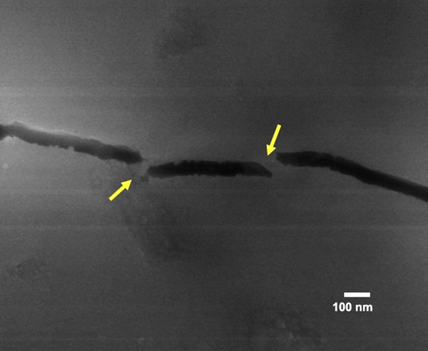
Image (SEM) of BNNT embedded in hydroxyapatite matrix shows radial cracking induced during an indentation test, indicating high interfacial strength between filler and matrix. Scale bar is 100 nm.197 Reprinted with permission. ©2011 Elsevier
Polymer matrix nanocomposites of thermoplastics and less common thermosets (e.g. epoxy resin198 – 202) have used processed clays16,203 – 206 and various nanoparticles,207 – 210 graphitic platelets and CNTs153,189,211 – 214 as dispersed filler materials, though other types of fillers 215 215,216 – especially carbon nanofibres202,217 – 219 (Fig. 15) – may also be used.200,220 – 222 In many cases, the goal is to reduce the amount of filler required compared with microscale counterparts. The higher surface-to-volume ratio material can provide greater interfacial effects for the same loadings in order to stiffen or toughen a polymer while preserving its low density, though there are numerous other reasons for using polymer–matrix nanoparticle composites (PNCs).
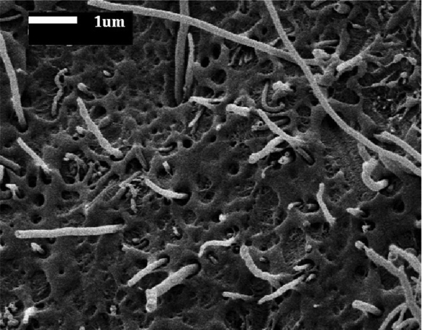
Image (SEM) of carbon nanofibres pre-coated with high-density polyethylene (HDPE) that exhibit strikingly low interfacial strength (obvious zones of non-wetting or voids) within an HDPE matrix after fracture.217 Reprinted with permission. ©2011 Elsevier
It is generally held that nanoparticle, nanofibre and nanoplatelet fillers that disperse well in a polymer (that is, are chemically compatible and form a strong interface) will strengthen it by inducing a greater volume fraction of crystallinity or semicrystallinity at the nanofiller/matrix interface, or what might be better denoted as an interphase. However, a strength increase due to improved load transfer to higher modulus fillers, especially for fibrous elements, is a substantive contribution to the mechanical effect. Extreme modulus fillers like graphene,223 CNTs224 and nanocrystalline diamond225 would then hold the much-hoped-for promise of ultra-strong PNCs if their polymer compatibilities provide enough interfacial strength, which would seem to point towards some optimised covalent bonding and filler alignment, weave or ply patterning depending upon the desired mode of applied stress. Multi-walled CNTs of high aspect ratio with smaller diameters (∼10 nm) can increase stiffness and fatigue toughness (against crack growth) by a greater factor than other carbon-based fillers,201 though there are concerns with MWCNT internal morphology related to buckling and interlayer rotations that clearly limited their ultimate contributions in composite strength more than for SWCNTs.
Polymer–matrix nanoparticle composites consisting of roughly spherical nanoparticles have been studied using many different metallic and ceramic colloids providing a broad range of material properties as additives to the system, whether hardness or ductility, insulating or conducting, transparent, opaque or photoactive.200,203,204,220 – 222,226,227 The same general requirement holds of good filler/matrix interfacial compatibility whether to enhance mechanical performance specifically or merely to maintain structural integrity and durability under less-demanding stresses.
In order to construct successful models for nanocomposites, multiscale and/or hierarchical approaches seem to be inevitable.25 One study of CNT-doped polymers with electromechanical properties has integrated the atomistic simulations for single CNTs into a multiscale platform with microscale load transfer from the polymer matrix to the CNTs to predict distortions under axial strain.228 This type of blended property scenario, e.g. material strain and electrical conductivity, is intriguing because it illustrates the potential to measure nanomechanical effects without the need for microscopy for some nanocomposites. With an appropriately validated model to interpret electromechanical data, it may soon be feasible to follow internal composite changes via piezoresistance over the course of a tensile stress–strain experiment: increased or decreased alignment of CNT fibres over certain number of cycles, interfacial breakdown between matrix and CNT based on electron depletion effects, or even a straightforward determination of composite fabrication quality without having to test mechanically or with electron microscopy. Other polymer nanocomposite types and/or modes of mechanical testing could also be incorporated into multiscale models in the future, such as for the effects of filler CNT diameter, aspect ratio, volume fraction and waviness, 114 114,229 reactions in MWCNT composites for torsional loading and buckling129 and elastic coatings.230 These types of system approaches represent substantial increases in complexity and will likely exemplify the benefits of coordinated interdisciplinary efforts.
Complex (biomaterial) systems
As if the lack of understanding in nanomechanical properties and measurements of metallic and ceramic objects and systems were not daunting enough, it would seem that even a thoroughly stated mechanical problem in a biological system might be beyond scientific grasp in comparison. The complete and rigorous treatment in matching theoretical modelling with experimental data from the atomistic scale through nanomaterials to bulk phase behaviour of gold or graphene, as quintessential examples, seems almost trivial – and yet this still eludes our collective investigatory capabilities – compared with the full complexity imagined for bionanomechanical studies on something like motor proteins:231 atoms-to-amino acids, polypeptides-to-protein aggregates and muscle cells-to-tissues. Recent mechanical analysis at the nanoscale for biological materials has included proteins,232 – 239 single cells,240 – 247 membranes248 – 250 and nuclei,251 biofilms,252 hair253 and skin.254 These may all exceed interpretative capacities at present for rigorous mechanistic understanding of their properties, but other natural biocomposites are more accessible, such as shell,255 – 257 enamel,258 bone232,259 – 263 and other mineralised materials264 (see Fig. 16).
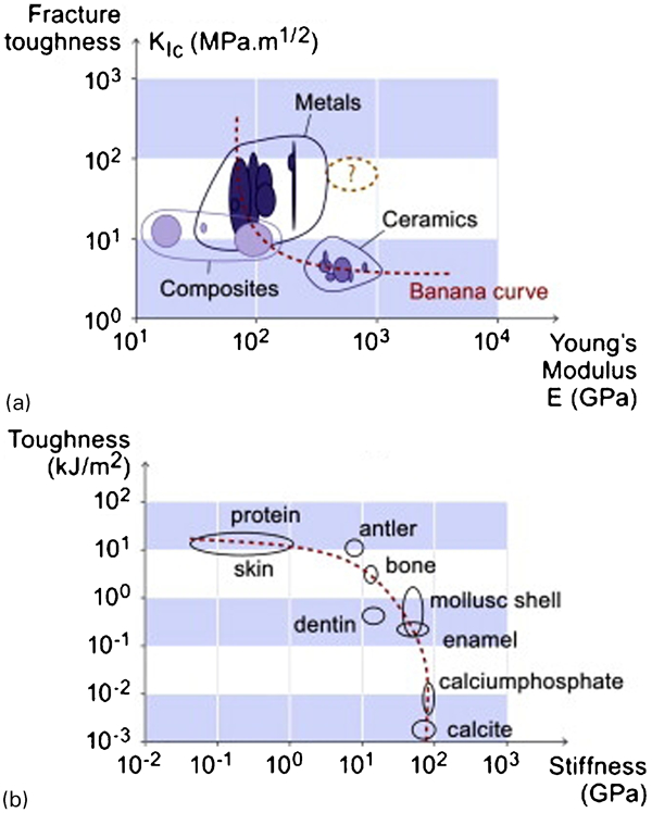
General magnitudes and ranges of toughness and stiffness in a metals, ceramics and synthetic composite materials compared with b biologically generated materials suggest opposing trends whereby synthetic composite design might imitate biomaterials to produce higher toughness and strength materials.259 Reprinted with permission. ©2009 Elsevier
One of the more significant aspects to biomaterial morphology is the distinctive hierarchy of structure in descending scale from macroscopic to molecular, often with several levels of obvious differences in characteristics.25, 257 The hierarchical nature appears to impact strength by reducing hardness as measured on increasing length scales (e.g. via greater probability of defects) and by increasing toughness (e.g. inhibiting crack propagation) concomitantly. The two competing trends provide a net balance of better durability in some general fashion, even before invoking any self-healing mechanisms. The very nature of morphological differences between the various scales of biomaterial hierarchy presents an array of mechanical behaviours with their manifold deformation and failure mechanisms, making a thorough understanding of these complex systems costly in effort, dollars and time. The review by Meyers et al. 257 takes an increasingly popular materials science approach to biological constructs that is an equally valuable read for the classic materials engineers who have not yet been exposed to the biosciences in depth.
In no other arena of nanostructured materials behaviour is the need for hierarchical computation in mechanics more relevant than for biological structures, most of which are protein based. In the emerging cross-discipline of ‘materiomics,’ Buehler et al.2 hope to formulate structure–process–property relationships that would allow interpretation and design of biomaterials, like bone and silk, by constraints on deformation and fracture requirements. Their extensive review on the few fairly well-understood examples, including beta sheets and alpha helices, illustrates the order of magnitude increase in difficulty to model biomechanical measurements for progress on deformation mechanisms and size effects in these incredibly complex systems with molecular unwinding, intermolecular and intramolecular slipping, covalent bond rupture, bond angle rotations and bending, ensemble hydrogen-bond breaking, and protein domain rupturing. Hydrogen-bond rupture is offered as a fundamental analogy in biomaterials to dislocation nucleation and propagation in ductile metals, for example. In spite of the apparent simplicity in such a reductionist view, the nanoscale mechanisms for even well-studied biostructures such as silk and beta-sheet proteins remain uncertain.
Perhaps the greatest complication to biological materials is not in the obvious atomic and/or molecular constituency or even in the biomaterial hierarchy but in the nature of being actively responsive, e.g. alive, mobile/motile,231, 265 self-healing,266 mechanosensing,267 etc., rather than passively responsive in the manner of merely physical reactions via elastic, plastic, viscous, electric, magnetic, thermal or other physical impetus being transmitted, reflected and absorbed in non-living matter.144,151,268 – 270 Of course, the distinction blurs somewhere between inanimate reaction and biological activity. One general approach is to understand first the smaller parts of complex biosystems. A recent review on cell mobility questions conventional dogma that maintains motor proteins alone are responsible for autonomous cellular motion and suggests that ubiquitous actin filaments or microtubules are also significant participants in the nanoscale mechanical motions of cells – not merely mechanical responders – via the cytoskeleton conformational changes.231, 271
A newly proposed theory model completes deformation recovery and returns to initial stiffness as observed in certain self-healing protein-based biopolymers under tensile stresses.266 These soft but strong biomaterials undergo unstrained-to-strained state changes via macromolecular structural (phase) conversions of some pseudo-random fraction of the network’s constituents from α-helix to β-sheet configurations in order to accomplish macroscopic deformations. The superelastic biopolymers are mechanically distinct from both common elastomers and SMAs due to loading/unloading hysteresis in the protein materials with no hysteresis in loading/reloading nor any apparent stress softening typical of elastomeric materials. The instantaneous deformation does not appear elastic yet the self-healing property provides perfect mechanical recovery.
Other polymeric gels and soft tissues have also been studied though nanoindentation measurements that illustrate a particular difficulty with very compliant materials10 compared with the more traditional metals and ceramics that have dominated our interests until more recently. The AFM is most suited for these investigations by using the colloidal probe method, where an ideal nanoparticle is attached to the cantilever rather than using the much sharper and small silicon, silicon nitride or diamond tips. In this way, local stresses can be reduced and yet nanoscale deformations are still feasible. The critical review by Lin and Horkay of interpretational models for separating significant adhesion effects from other mechanical processes outlines the main concerns for nanoindentation, indicating that there may be no linear elastic limit in some biological materials and that multimode models are needed for fitting the large strain behaviours of importance in softer materials.
Collagen fibrils, proteins and DNA
While the macromolecular mechanics of biochemistry have been replicating and implementing nanomechanical, nanochemomechanical and nanoelectromechanical systems (NEMS) since the first days of life as we understand it, they are much more difficult to study in a quantitative fashion, compared with more rigid constructs of inorganic components in three-dimensional shapes (e.g. nanosprings and synthetic NEMS) that have become available. Biomolecules and naturally occurring biological structures of nanoscale dimensions often seem to be overlooked by some of the nanomechanics community when attempting to formulate general rules and mechanistic understanding of processes at the nanoscale.2, 257, 272 Likely reasons for this include: unfamiliarity – since materials science has been traditionally a discipline concerned more with metals, ceramics and similar synthetics; the complexity of macromolecular behaviour; and their property values that fall outside of a classic range of application and interest, which could all have been said of synthetic polymers in general before the nature of DNA had even been elucidated. Biological and biomedical scientists and practitioners have, until more recently, constituted the group majority of investigators concerned with biomacromolecules and their physicochemical properties. Our current age of interdisciplinarity – if history so chooses such an awkward title – is harkening back in some ways to the earlier eras of science and engineering where one investigator had to know more than just a little bit of almost everything.
Collagen, its several types and the fibrils, fibres and tissues that they form in hierarchical ubiquity within animals and across taxonomic ranks comprise one key subject of biomaterial mechanics, often studied at a complex systems scale (Fig. 17).2, 273, 274 Naturally occurring collagen fibrils consist of molecular lengths of roughly 200–400 nm, where an optimal (so-called critical) value of 200 nm appears to provide the best strength and energy dissipation in a deformation tissue.234 The main deformation modes in tropocollagen are homogenous shear or slip pulsing, though molecular fracture or rupture will happen with higher cross-link densities, for example. While the viscoelasticity of collagen tissues has been studied for decades, the development of AFM and MEMS have recently provided fibril data on elastic modulus, hardness, viscoelastic creep and relaxation times (Fig. 18).238
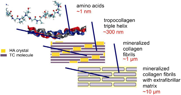
Four of the seven hierarchical structures of bone, from the macromolecular level of amino acids and proteins through the microscale of mineral–biopolymer compositing, details the triple–helix of tropocollagen (TC) that assembles into fibrils (not depicted at the individual level) with hydroxyapatite (HA) mineralisation. These mineralised collagen fibrils are assembled into arrays with an extrafibrillar matrix.2 Reprinted with permission. ©2008 Elsevier
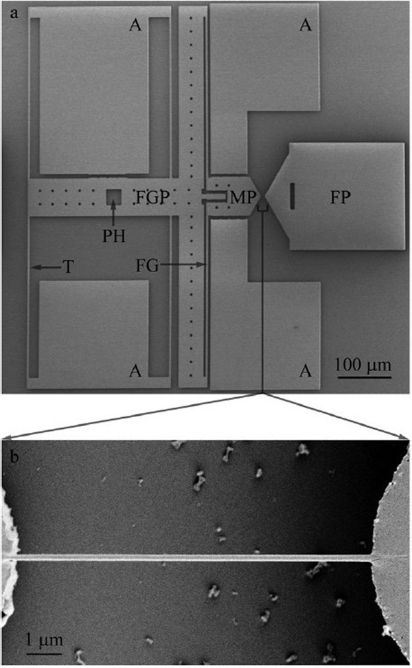
Microelectromechanical system device for measuring creep and stress relaxation for a 1D object (e.g. fibre or wire), such as the collagen fibril under test. a Movable and fixed pads (MP and FP) strain the fibril b in tension while a force-gauge assembly (FG and FGP) with tethers and anchors (T and A) provide output for calculating stress.238 Reprinted with permission. ©2011 Elsevier
In contrast with comparable metallic and ceramic structures, the much greater inherent variability of interdependent parameters like molecular weight distribution, cross-linking and molecular packing produces larger spreads in experimental data. Full MD simulations are not yet feasible to interpret fibril behaviour directly,275 though tensile uncoiling calculations support cross-links as a primary strengthening source and predict the largest strains being distant from cross-linked regions and hydration state as a variable in mechanical behaviour.239 Other simulations work also suggested that cross-links prevent or reduce energy absorption232 and that mechanical deformations should occur through helix disruption before (at lower forces) cross-links would rupture.233 However, investigators should be warned from making inferences on practical biomaterials behaviour based on force predictors alone, since macromolecular interactions are generally governed by kinetics as well as thermodynamic potentials; for example, determination of collagen elastic modulus276 and molecular rupture forces277, 278 are rate-dependent, not merely force or stress dependent.248, 279 Evans and his co-workers were among the first to demonstrate this rate dependence through direct single-molecule studies in the mid-1990s when earlier and contemporary AFM measurements on ligand-receptor separation forces where applying a constant rupture force as an unfortunate consequence of instrument limitations to relatively slow pulling rates compared with time-scales relevant for molecular motions of relaxation and reconfiguration.
Single molecule force spectroscopy – a specific technique within AFM and biomembrane force probe (BFP) methods (Fig. 19) – now provides a rate-dependent method for measuring interactions that have addressed elasto-mechanical behaviour of peptide stretching and cross-linking,280 mechanical stability of elastomeric proteins against unfolding,236 or denaturation, as affected by pH and electrostatic interactions,281 strength of antibody binding and forces exerted for folding, unfolding and refolding between conformational states,282 protein aggregation processes and how they impact the structural properties,283 dynamics of protein/cofactor binding/folding,284 and many other topics over the past 20 years or more.285 Among the many challenges to true nanomechanical measurements on macromolecules and their related systems are some very basic issues of limited ability to manipulate and count the molecules involved in the test directly, measurement of static versus dynamic forces and energies, knowing the strength and mechanical behaviour of the anchoring surfaces or ‘clamps’ and the precise geometry of the pulling test being performed.286 Though there are partial solutions to most of these problems,14, 236 they are very tedious and costly in time, equipment and expertise to approach an ideal and comprehensive measurement routine on individual or small systems of macromolecules, for example, to develop a full understanding of protein nanomechanics – stability, energetics and time dependence of folding/unfolding. Of great direct concern to many biologically relevant sciences, these fundamental underpinnings are likely to be significant to advanced synthetic materials inspired by spider silk,2 to name a popular target.
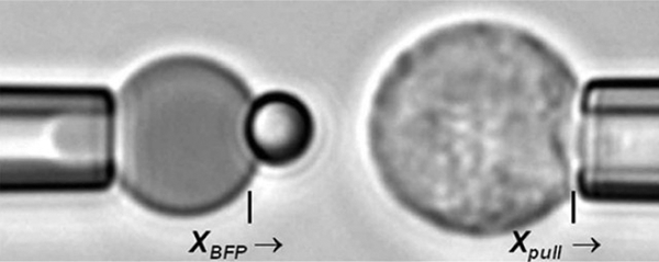
Biomembrane force probe (BFP) arrangement using two pipettes to hold a red blood cell (left) with a smaller, attached glass microsphere 2 μm in diameter and a larger polymorphonuclear leukocyte (right). Vacuum pressure is adjusted on the RBC to control the effective spring constant anchoring the interaction exhibited between the modified microsphere surface and the leukocyte surface to measure bonding, stretching and bond rupture forces.278 Reprinted with permission. ©2010 Elsevier
The AFM and MEMS measurements may be well suited for bionanomechanical studies on protein signalling or response by opening or closing binding sites to chemical pathways through configurational rearrangements.287 A much more complicated scenario than collagen fibril or muscle protein segment testing is a relevant mechanical measurement for membrane proteins using AFM.288 Since relatively small changes in the chemical environment can dramatically alter macromolecular configurations and thus behaviour, there is strong motivation to investigate folding and unfolding as a nanomechanical process in situ. However, much like the quantum mechanical observer affecting an experimental outcome by the act of watching, the AFM probe necessarily disturbs the system from its natural state(s) artificially – even for intermittent and non-contact modes but to lesser extents respectively – thus becoming part of an aberrant system that may be as irrelevant to the ultimate goal as other conventional approaches. Not all in situ AFM or other probing techniques automatically defeat their own purposes for macromolecular testing, CNTs being an obvious exclusion. Experimental determination of protein filament (i.e. microtubule) strength and buckling would be more challenging than for MWCNTs of similar size due to the much softer nature of the biomacromolecular construct, though new methods for blended continuum-atomistic modelling now await supporting evidence to advance our understanding of cytoskeletal structure and performance.289
Nucleic acid-based macromolecules (DNAs, RNAs, LNAs, PNAs, etc.) are at once both simpler and more complex than the proteins discussed previously in that DNAs – and perhaps their RNA counterparts290 and modified nucleic acids by extension291 – have a more facile route to design and fabrication of human-scale-inspired nanomechanical structures.292 – 294 The notions of elasticity and failure, among others, remain key to our understanding of nanomechanics even down to the penultimate scale of double-stranded (ds) DNA for cellular processes and synthetic nucleic acid structural behaviour.295 Recent mechanical bending and torsion comparisons of dsDNA and three-dimensional origami DNA structures of four and six helix bundles were conducted by magnetic tweezers using one anchored end of the DNA structure to stretch or twist the free, magnetic-beaded end with a magnetic field, finding greater bending rigidity and unexpectedly low torsional rigidity in the DNA origami.292 As the diverse areas of materials science merge more intricately, these kinds of single molecule nanomechanical studies on biological species will become increasingly relevant, even though they may seem too disparate from more traditional mechanics of other nanomaterials.
Tissue networks, whole cells and natural biocomposites
Isotropic fibrin networks are also meso-to-macroscale structures that exhibit great extendibility and compressibility due to a macromolecular folding and unfolding, which provides a fundamentally nanoscale mechanism for mechanical behaviour. One particular ‘eight-chain’ worm-like force-stretch model describes how these protein networks can show negative compressibilities and Poisson’s ratios greater than one during stretching,296 i.e. unfolding ensemble (Fig. 20). While the model is not an explicit, structural simulacrum of the protein network, it does well in modelling filament-scale behaviour, conducive to molecular design towards desired mechanical properties. In practice, fibre alignment from tensile stress can be measured by the extent of optical polarisation with the aid of dyes. Anisotropic models for woven, hierarchical constructs have also been developed with design implementation potential towards mechanical property matching, with a specific interest towards biological tissues like tendons, cartilage and other structure tissues.297 As one would expect, they predict decreasing elasticity with woven fibre angle and hierarchical level increases.
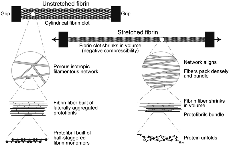
Schematic of fibrin sample under tensile testing illustrates altered hierarchical structuring down to macromolecular rearrangements responsible for large-strain elasticity.296 Reprinted with permission. ©2011 Elsevier
Measuring the hardness or elasticity/viscoelasticity of individual cells with AFM,298 optical tweezers299 and other similar techniques can provide a wealth of mechanical data with dubious mechanistic interpretations due to morphological complexity (Fig. 21). Adhesion between cells or a cell and some second body or substrate may also be studied by micropipette experiments, the BFP,279 surface forces apparatus, as well as AFM,300 which also accesses local mechanical properties at the cell membrane, including ligand–receptor interactions, protein folding or reconfiguration and friction.298 In spite of the rich instrumentation toolbox for these types of mechanical measurements, there is still no unified, universal or rigorous understanding of the governing mechanisms in these complex systems. With specific regard to whole-cell mechanical response, hardness and/or viscoelasticity has been associated with pathological changes, where stiffness increases with age247 and can decrease with infection301 and the onset of cell death (e.g. apoptosis).243
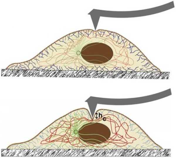
Atomic force microscopy nanoindentation schematic cross-section of substrate-supported cell. Atomic force microscopy tip indents the cell membrane (top) and interacts primarily with the actin cytoskeleton (short/blue fibres at interfaces) near the membrane interface. Only after relatively large loading forces and global deformation (bottom) does the probe interact with primarily with the material properties of the underlying intercellular matrix and organelles, such as the nucleus (dark ellipsoid). The measured elastic modulus of a cell is typically estimated from this second indentation phase where the intermediate filament network (long/red fibres surrounding nucleus) is believed to determine the elasticity.246 Adapted with permission. ©2011 Elsevier
The main contributions to cellular mechanical properties appear to be the cytoskeleton morphology and the general level of hydration,247 though the membrane, nucleus, other organelles and intermediate filament network246, 302, 303 are significant as well. From a purely simplistic mechanical point of view, it is apparent why cells and related biological materials would need to maintain a specific character and magnitude of behaviour in one or more modes of operation to perform optimally, including an ability to maintain shape at times and then also to undergo large reversible deformation at other times. The study of bionanomechanics that provides this living quality requires in situ measurements under physiological conditions,299 which is the great continuing challenge, and the method of measurement in these soft systems is often a complicating factor. For example, determining the contributions of whole-cell deformation and of local probe deflection when using AFM is non-trivial.298 A prime example is the dynamic nanoindentation study on mice heart valve tissue, where the stiffer melanocytes in the tissue matrix make it difficult to quantify the effects of melanin concentration in regulating biomechanical properties.304
An array of microscopic cellular observations over several decades coupled with much more recent macromolecular knowledge derived from modelling and visualisation has generated much interest in bio-inspired nanomaterials, biomimetics, nanomechanical machines, and the like. The radial buckling of microtubules, which are actually nanostructured cytoskeletal proteins larger than most CNTs in diameter, was recently shown to have a property size dependence based on review of experimental results against a new model.305 The findings suggest that microtubule buckling is fundamentally dependent on some as-yet uncertain characteristic length-scale (here a fitting parameter; earlier in theory connected to the persistence length306) analogous perhaps to the carbon–carbon bond length for CNT nanoscale size effect on mechanical properties; of course, the significant spread in measured longitudinal and circumferential Young’s moduli depends on the precise testing conditions as well as morphological distributions among samples.
The particular mechanical properties that make bone such an interesting composite material for study originate from hierarchical morphology of collagen fibrils and mineral crystals276 building from macromolecules and nanoparticles into the organism-scale of the largest mammals. The particular levels of structural heterogeneity in bone provide a model for optimising composite strength in designed synthetics, whether for biomimetics or other structural materials, even though there is still debate as to whether material heterogeneity is a benefit or a liability in bone.263 Nanoscale heterogeneity can promote energy dissipation (namely inelastic behaviour) but also increase stress concentration and/or strain localisation that could lead collectively to net strengthening or weakening. The highly complex scenario must include considerations for shape and distribution effects of material heterogeneity as well as size scale and volume fraction. Findings to date have attempted to define a critical length or range for nanocomposite structures for which some mode of strength or toughness is optimised. It is not clear if this critical dimension would fall into the nanoscale for all hierarchically heterogeneous materials, and having size-dependent properties within this range adds further complexity to future prospects.
In the case of bovine cortical bone studied with nanoindentation, a critical length of 200 nm (Ref. 234) – or roughly the dimensional order of collagen fibrils in the bone matrix – was determined to mark a lower bound for generally uniform inelastic energy dissipation; that is, indenters (in this strength-testing case) of diameter smaller than this critical length would experience significantly increasing variations with diameter in the bone’s ability to dissipate energy rather than propagate damage, such as a crack. Human cortical bone was also recently tested for compressive strength and yielding to show that internal strains of mineral crystals and collagen fibrils that are not aligned with the load direction dictate failure behaviour, with the bone mineral straining roughly twice as much as the fibrils according to X-ray measurements.261 Surprisingly, those crystals and fibrils aligned in the compression direction appear undamaged after yielding, but direct investigation of off-axis aligned constituents is needed to confirm the mode(s) for microscale damage and post-yield deformation.
Nacre in seashells, another bone-like biocomposite only tougher than bone or enamel, exhibits a toughening of its calcium carbonate matrix (aragonite) by three or so orders of magnitude from roughly 5% by volume biopolymer filler257, 259 (Fig. 22). The physical mechanisms for toughening are via interfacial contacts mediated by 20–30 nm interphase of proteins and chitin undergoing mechanical sliding between tablet structures, interlocking due to tablet waviness (in the range of about 50–200 nm) and inclusions of 30 nm grains, tablet mineral bridging (nanoscale fusion) and visco-plastic blocking of crack formations.259 The organic glue-like matrix307 interfacing with the mineral phase in the composite is analogous to the grain boundary interphase of metals and ceramics in both a morphological sense as well as its mechanical role. The precise contribution of mechanisms is uncertain – what features and mechanisms are generally governing or merely consequential. The rather complicated tablet-stacking morphology applied hierarchically is under consideration for next-generation composite material design and formulation.
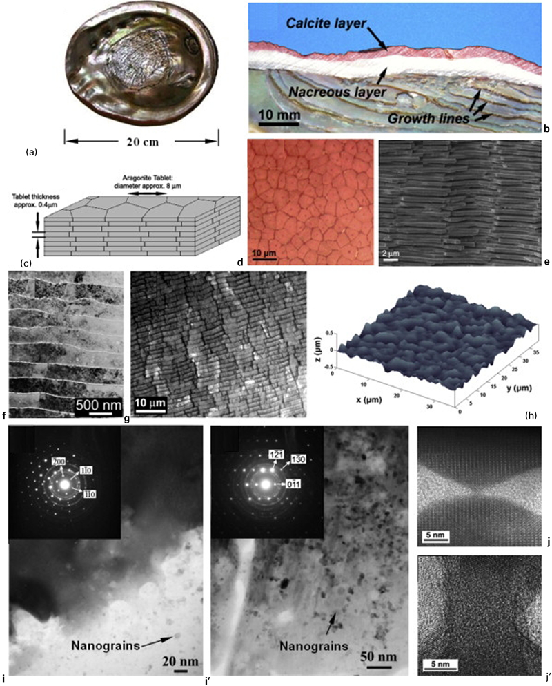
Hierarchical levels on structure in a red abalone shell nacre; b physical cross-section of shell; c schematic of tablet layering in nacre showing plates (photo d) of several micrometres in width and (SEM image e) ∼400 nm thick; f TEM of tablet layers and g comparison with larger features in mussel shell nacre; h laser profilometry map of nacre tablet; i, i' TEM images and diffraction patterns for aragonite nanograins; j, j' high-resolution TEM of aragonite asperity and bridge responsible for strengthening tablet interactions.259 Reprinted with permission. ©2009 Elsevier
Dental enamels were also found to have mechanical scale effects from indentation behaviour, though the morphological connection to mechanism(s) is not yet clear among the likely events of protein layer rupture or breakage, interfacial slipping, viscoelasticity, crystallite rotation and/or cracking.258 Each level of the hierarchical enamel structure showed different mechanical response, including a generally decreasing elastic limit with increasing indenter contact area, where enamels exhibited plastic deformation beyond the elastic limit with nanoindenters and cracking with microscale indenters. Some experiments indicate that – somewhat similar to nacre – it is the relatively minor component of protein glue only a few nanometres thick that has the greatest relative impact on mechanical properties, including higher energy absorption and greater indentation creep behaviour.308 It appears that nanoscale shearing between crystallite platelets, like the nacre tablets, absorbs energy without appearing mechanically elastic due to protein unfolding, which breaks many non-covalent bonds that can reform (e.g. elastic or inelastic self-healing) and still contribute to a viscoelastic or creep-like behaviour of the biocomposite.
Finally, time-dependent nanomechanical measurements of cartilage determined that their aggrecan constituents (protein-based biopolymer) increase relaxation times and stabilise the mechanical response against strain amplitude variations.309 The cartilage tissue is a complex, hydrated and nanoporous gel of extracellular matrix macromolecules (mostly collagen as fibrils and aggrecan as aggregates) and embedded chondrocyte cells. Fluid-flow-induced poroelasticity was found to be the dominant mechanism for energy dissipation under oscillatory stresses, though relaxation (longer timescales) seems mostly governed by the viscoelastic nature of the matrix-filler solids. This particular study is one example of how to approach the highly convoluted material nature of biological tissues towards isolating the mechanical role of a constituent species. Of course, the relative contribution of one component becomes quantifiable with respect to the whole composite only after the rest of the components and their mechanical contributions to the tissue properties are understood. For example, the direct impact of changing and removing some of the constituent adhesive contacts within the matrix is not evident in this study. These prospects inevitably point to the need for rigorous mechanical insights concerning chondrocytes, the extracellular matrix, hydration effects on a charged hydrogel and the nature of poroelasticity in a heterogeneous hierarchical biomaterial. That outlook makes design and testing of synthetic hydrogel formulations for mechanical property behaviour at the nanoscale appear almost trivial.
Nanoelectromechanical systems
One of the major motivations for the recent surge in nanomechanical research is to allow for better design of MEMS and NEMS. Diverse aspects of MEMS and their behaviours have been studied241,310 – 322 for much longer than their smaller counterparts on which we are solely focused for the present review. While some aspects of MEMS certainly fall under the broad goal of considering the deformation measurements and mechanisms of nanostructured materials, the more studied and reported details concern fabrication, functional application and tribology rather than quantified efforts towards understanding the mechanical properties of interest herein.
Nanoelectromechanical systems are a concept for the twenty-first century to birth. None of the examples reviewed offer realised NEMS to the inspirational degree imagined by many. There are obvious, natural roles for CNTs,323 shape-memory materials and other primary nanostructures and molecules in this field,45,237,292,293,324 – 326 but the marriage of two or more immature areas of investigation will be laborious. True nanoscale mechanical devices have been essentially restricted to bending and resonating beams, largely because of the lack of adequate substrates and surface properties (mostly limited to silicon-based materials) to allow the desired motions, much like their larger counterparts. As such, one of the most common applications of NEMS (and MEMS) research is towards detection and sensing.240, 327 Cantilevered nanobeams are very sensitive to mass loading changes and have relatively easy potential for vast parallel fabrication and operation towards multiplexing biochemical sensors and diagnostics with proteins and nucleic acids for lab-on-a-chip miniaturisation and purportedly label-free protocols;328 but there must still be some chemical selectivity for each nanocantilever to perform its designed intent, whether by direction functionalisation, which is essentially similar to the need for a label in the conventional sense, or by use of selective media, which have their our inherent difficulties and limitations perhaps even more so than traditional label-based assays.
It should be pointed out that good nanomechanical knowledge is vital for the fabrication of reproducible NEMS devices and for more complex constructs than currently exist, and this seems to be largely missing from the literature where demonstrating operation appears to be the main purpose rather than fundamental and quantitative understanding of mechanical properties and behaviours at the nanoscale. One of the more pertinent examples reviews the fabrication of shell nanostructures for use as building blocks of more complex M/NEMS.318 This process involves the use of a strained hetero-film deposited on a sacrificial substrate layer; upon the removal of the substrate, the main hetero-film bends or buckles, resulting in curved nanostructures with finely controllable radius. These shell structures are capable of generating up to 105 N cm−2, can be made of many material types and are fabricated with a process which is fully compatible with current lithography techniques for integrated circuits. Further, Prinz and co-workers have developed a novel nano-actuator design employing corrugated films with a dynamic number of corrugation periods that eliminates the ‘pull-in’ problem commonly associated with two-plate actuators. Nano-shells have also been used to create tubular microjets329 and actuators for driving self-propelled micro-swimmers.330
It is not surprising that a large portion of the recent NEMS literature is devoted to the applications of CNTs in nanoscale devices, especially as sensors but also with perceived potential as motors, switches and oscillators.100, 313, 315, 316 In addition, CNTs have been employed as pressure sensors by taking advantage of shifts in their Raman spectra331 and piezoelectric response,332 and as macroscopic strain sensors by embedding SWCNTs on polymer substrates and/or as CNT thin films.333, 334 Nanoelectromechanical system switches have been constructed using CNTs which demonstrate particularly low actuation voltage, high switching rates and high radio frequency (RF) power. These switches are built following a handful of design archetypes generally based on a CNT suspended between electrodes335 or an array of vertically aligned CNTs;316, 336, 337 however, it should be noted that both of these approaches are prone to RF self-actuation and RF latching failures. Nevertheless, several devices that incorporate similar switches have long since been realised, including RAM, actuators and nano-tweezers, to name a few.323,338 – 344
Particular to the resonant properties of CNTs (as well as other nanostructures, as discussed later) in NEMS are nanomechanical antennas.316, 345, 346 While there are major challenges associated with this use (i.e. high ohmic losses and relaxation frequencies, impedance matching and low radiation efficiency),347 – 349 such devices show great promise for a variety of applications, including wireless communications and biosensing – one of the most popular subfields of nanoscience and engineering. However, biosensor concepts most often take some advantage of the chemical or electrical properties of the CNT rather than mechanical.321 Resonator-based chemical and biological NEMS are advantageous for a number of reasons. One of the major benefits to nano-resonators is that, unlike cantilevers or other chemically modified sensors, the sensitivity of resonators actually improves as they are scaled down. This leads to some remarkable detection capabilities; for instance, Peng et al. have created an oscillator that can operate in air at frequencies reaching 1·3 GHz (with Q = 10),350 and Li et al. have demonstrated ultra-high frequency resonator sensors capable of individual-molecule identification, with a detection limit approaching 1 attogram.351 Jensen et al. have reported detection of single gold atoms using a CNT resonator at room temperature under an ultra-high vacuum with a noise level of 0·13 zg Hz−0·5.352 Such high sensitivities are attractive for many applications, particularly in the biological sciences where specific cell detection via protein assay has become a major objective. Craighead and co-workers have pioneered single-cell detection via nanostructure resonators as well as virus and DNA detection strategies.353 Single-cell detections in an aqueous environment have also been achieved using a suspended microchannel resonator capable of maintaining a high Q factor.354
There are still significant limitations to resonator-based sensor technology. Nano-resonators tend to exhibit sizeable losses from dissipation when operated in aqueous environments; however, recent work has demonstrated an advantage of viscous damping to identify components selectively in a gas mixture.355 Many studies also relied heavily on physisorption or non-specific particle adhesion to the nano-resonator surface rather than targeted chemisorption or specific binding.351,356 – 359 Investigation into the possibility of multiplexed resonator sensor arrays is a promising target.360
Previous work in nanoscale power generation361 – 363 took advantage of CNT properties to create electric motors and converters and more recently capitalised on a lack of central symmetry in the piezoelectric ZnO crystal structure of a single-wire nano-generator.364 The future concept for harvesting waste energy from common biomechanical motions such as heartbeats, breathing or walking has already been demonstrated by connecting to a human finger and a hamster running in a wheel.365 By connecting a multitude of single-wire generators, a 20 000-nanowire generator has been built capable of delivering voltages of ∼1·2 V with an average power density of approximately 70 nW cm−2.366 Such devices offer a plethora of options for portable electronics and biomedical implant power supplies based on nanomechanical fundamentals.
Nanobots, elevators to space and the twenty-first century outlook
The authors are among one camp of researchers and enthusiasts whose view admits an increasing use of nanostructured materials in everyday products that does not allow nanotechnology as much more than a budding industry yet, when considered against the history of science and technology. Scientists and engineers involved with developing the ‘nanosciences’ into many application directions do well to avoid hyperbole when explaining to any audience the potential virtues and vices of what may someday be a technological, and thus societal, revolution. While our imaginations should not be discounted, a futuristic outlook with firm foundations in reality may produce more likely prospects with fewer false hopes than science fiction. In some circles, there seems a tendency to herald the Holy Grails of science – indestructible materials, affordable trips into space, the extinction of cancer, etc. – and to leap over the intermediate and in many cases, necessary advancements that should perhaps be even more enticing because they are more probable and imminent.
The consequences of creative vision in science and technology include unforeseen pitfalls as well as unknown innovations, like daVinci’s flying wings and Einstein’s cosmological constant. Many more intervening years than seem necessary have separated genius from humans building the first airplanes, and Einstein’s self-proclaimed greatest blunder may now have a use, though not as originally invented. It would seem likely that today’s fictional yearnings for nanobots326, 367, 368 and space elevators369 – 376 for lifting us beyond the atmosphere may end up in realised states quite different from our imaginations. Ultra-strong cables made of long, woven CNT ropes may be more or less feasible377 – 381 than new steels382 or some as-yet undiscovered materials383 for lofting payloads into low-earth orbit along a mechanical conveyor line from a high-altitude platform to a counter-weighted satellite without a conventional process of rocketing or flying. Various space elevator designs fancied and predicted by a number of futurists may fail for manifold reasons having no correlation with CNT-based mechanical strength limitations. Nanobots, however, have existed in many forms within the machinery of life and merely await our derivative mimicry to proliferate synthetic materials and devices suited for our whims and needs.231
The fabrication of DNA nanomechanical devices – so-called, molecular machines and 4D structures294 – has succeeded recently in producing autonomous walking macromolecules.326, 367, 368 The greatest difficulty in bionanomechanics is probably the same as for any mechanical study of nanomaterials: how to monitor configurational and chemical states. The problem is of course exacerbated in vivo and in vitro where most atomic and molecular resolution appears improbable at best as a routine method of interrogation of any but the most rudimentary constructs, where the precision and finesse of scanning probe tools seem far too coarse and invasive.294 In any case, the nanobot foundries to come are more likely to be beakers and cells rather than uber-cleanroom fabs. Another important aspect to this topic may be a better understanding of nanomechanical communications (namely vibrations including sound waves) between microorganisms that could facilitate process and design control over cellular synthesis.384
The almost venerable story of bottom-up or self-assembly versus top-down nanofabrication methodologies remains central to the discovery of twenty-first century technological innovations, whether pertaining to bulk production of extended nanomaterials for structural/mechanical operations or ultra-massive parallelisation of NEMS and synthetic bionanobots.45 The painfully obvious difficulty of nanomachining in a classic sense is well demonstrated by multiscale dynamic simulations.385 A spherical tool attempting to cut a 2 nm groove into a simulated aluminium single crystal reveals the disastrous deformation ensemble extending far into the surrounding matter and the continuing relaxation after tool removal (Fig. 23). Formulating the perfect elixir for DNA-nanobot self-replication in a beaker, though seemingly fantastical, seems roughly of the same low order of probability. Less popularised advances in nanostructured materials may be much nearer in development that may facilitate mechanical control and measurement advances and with them a growing knowledge of deformation and strength behaviours and mechanisms in formulated materials and design applications, whether for nanomechanical data storage,386 re-engineering the machinery of life,237 new instrumentation and measurement techniques,387 or fine-tuning physical properties of a nanocomposite through fabrication and processing.
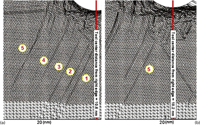
Multiscale simulation meshes of spherical cutting tool generating slip dislocations deep into the material from a 2 nm deep scratch illustrate the difficulty in nanomachining from a traditional approach.385 Reprinted with permission. ©2007 Elsevier
Concerning future prospects for the shorter term, there are certain incremental advancements that seem highly probable in the general arena of improving nanomaterial properties and knowledge of their fundamental nature. One highly sought after outcome for nanostructured materials is the capability to design and fabricate stronger materials by collectively fine-tuning formulation and processing towards an optimum that might be codified as ultra-strength. While this general notion, apart from nanomaterials per se, is precisely what the industrial revolution has undertaken for centuries with any key material property, contemporary developments portend continuing future progress through specific and new nanostructural engineering strategies such as elastic strain engineering155, 156 and grain boundary engineering9, 27 (with somewhat overlapping domains) towards particular product goals.
An in-depth review by Zhu and Li9 explained that increasing practical strength limits towards the upper bound of the ideal stress achievable (without defects but not including so-called free and ideal surfaces) can be accomplished by defeating material relaxation (namely inelastic strain) up to higher stress levels for dislocation, twinning, cracking, crazing, precipitation and/or diffusion. Zhu and Li concluded by suggesting that unifying concepts for materials strength may be found in morphological length scale-dependent activation volumes and temperature versus rate of strain sensitivities across deformation mechanisms that might be cogently mapped. If so, concerted efforts may lead to broadly useful scaling laws in nanostructured materials.
The aim of ultra-strength engineering would include making a bulk material stronger by physical rearrangement (e.g. processing), by modification with additives (e.g. new chemistry and new compositing) or by developing an entirely new formulation, all of which could and likely would include some nanostructural aspect(s) (e.g. a macroscopic CNT cable). The desired level and mode (e.g. tensile, compressive and shear) of strength would be informed, as usual, by restrictions of geometry, function, durability, toughness and aging among a host of other possible design requirements dictated by all magnitudes and directions of stress–strain and the ranges of their rates of change. The specific goal for ultra-strength would necessarily include not sacrificing the qualities of the other properties.
If ultra-strength engineering would ultimately be based on an unfolding reality that nanostructure becomes in some way a panacea, then the wrench in the works is an underdeveloped fundamental understanding of nanomaterials. An extensive review of surface stress effects in solid nanomechanics, focusing on continuum descriptions, concluded by suggesting that a fundamental understanding is likely to remain elusive until experimental designs are capable of monitoring changes to interfacial energies in non-idealised systems.11 With many investigators narrowly focused and with more simulations than extant measurements, great care is needed in the formulation/discovery of scaling laws, if they exist in a well-defined and widely applicable form. It may simply be that our current lack of knowledge makes the breadth of nanomaterials behaviour appear overly complex. Both modelling simulations and instrumentation capabilities will certainly need revolutionary advancements to find a pragmatic approach.
Robust, predictive modelling/computation has great potential for identifying areas of particular interest and perhaps saving time, money and efforts by suggesting experiments of lower priority or lesser scientific value.388 Of course, the continuous advancement in both qualitative and quantitative understanding of mechanical properties and their equilibrium and kinetic behaviours depends on strongly interdependent studies of physical testing with substantive modelling and simulations. The fundamental capabilities in both arenas – experimental and computational – appear sufficient today to address many of the most pressing questions but are still too labour-intensive and costly to be feasible for the rapid technological achievements that investigators imagine to be just on the horizon. Furthermore, the impractical nature of tracking and sorting volumes of modelling data towards relevant research and development targets – too much of which makes no comparison with physical experiments – foretells a growing hazard for reinventing the proverbial wheel. However, if a totally new kind of cyber-infrastructure can improve our plight, the goal of clarifying length-scale-dependent mechanical properties for nanomaterials – with rigorous phenomenology built into the governing equations – should produce a technology revolution akin to the assembly line, and if it can be accomplished for all categories of materials and not only some few but well-studied systems.
Concluding remarks
The breadth and depth of mechanical property studies on nanostructured materials as a whole allow a wide range of constitutive relationships. In some subsets of interest, there are clear trends and even quantifiable scaling laws in some sense, though they are far from rigorous yet. Even the Hall–Petch relationships or the Orowan strengthening mechanism, anchored in pre-nanomaterials-history, remain most used only after a semiquantitative fashion. Furthermore, these notions that have gained enough supporting data for some level of confidence are not universally applicable across the spectrum of material types, at least as far as is apparent from the current vantage. For example, polymeric structures and other cellular biomaterials do not conform to concepts of grains and grain boundaries in the way that metals and ceramics do. However, the potential for improvement on mechanical properties of synthetic materials is increasing just as the full nature of biological structures becomes realised and translated into design and fabrication techniques.
In the attempt to capture the full body of knowledge concerning nanomechanics in general, the rate of publication has exceeded the authors’ abilities to do justice to the efforts of many contributing investigators. One obvious weakness to this review – though as intended – is the focus on experimentation where substantive efforts in computational studies have also been accomplished to a high degree within the last 10 years. In spite of this, one obvious lacking point for the current state of knowledge is a sufficient magnitude of corroboration between experiments and modelling that will be necessary to make significant leaps in fundamental understanding of nanomechanical behaviour. The other at-present insurmountable obstacle is the cost in money and investigator hours. Many of the gaps in knowledge exist not because of capability but due to insufficient capacity coupled with degree of difficulty. Lingering questions about mechanisms for deformation and failure could be addressed within a reasonable time-frame, given a complete array of instrumentation and free access for every interested team of researchers. When a standard tensile test is routinely conducted with simultaneous field-emission SEM, high-resolution TEM, or X-ray diffraction like a cell culture is scrutinised under a fluorescence microscope, perhaps then it will feel like the twenty-first century has arrived for the mechanics of nanomaterials.
Interested audience members are strongly encouraged to use this article as their launching platform and to continue publishing concise review updates annually, both broad in scope and targeted, as a much needed service to help the scientific and engineering communities sort through and track the accelerated evolution of our technological landscape until this Information Age can produce sophisticated, autonomous, non-human filtering and synthesis programs that work more effectively.
Footnotes
Acknowledgements
The authors gratefully acknowledge research funding from the W. M. Keck Foundation that allowed pursuit of initial interests in nanomechanics more than a decade ago, and other historical support from the National Science Foundation (DMR-0619310), the NSF-Idaho EPSCoR Program (EPS-0132626 and EPS-0447689), the University of Idaho Biological Applications of Nanotechnology (BANTech) Center and the Idaho Research Council, all of which partially supported continuing research projects concerning the mechanical behaviour of nanowires, nanofibres and nanosprings, and their applications over the past 11 years.