
Abstract
Zirconium alloy cladding tubes used in nuclear fuel rods are susceptible to delayed hydride cracking, which is a time dependent crack growth process resulting from the stress assisted diffusion of hydrogen to the crack tip, followed by the formation of radial hydrides and the subsequent fracture of the hydrides in the crack tip region. This article reviews the current understanding of the delayed hydride cracking behaviour of zirconium alloy cladding tubes for fuel rods, focusing on the degradation mechanisms in high burnup fuel rods and transient loading scenarios, which could potentially lead to substantial changes in the hydride microstructure and cladding failure by delayed hydride cracking following removal from the reactor and during storage and disposal of spent nuclear fuel rods in a waste repository. A brief summary of the general characteristics of delayed hydride cracking in zirconium alloy cladding is presented first. Relevant information on the cladding stresses under various usage conditions is then compiled and categorised into several characteristic stress transients that can be anticipated during reactor operation. Delayed hydride cracking in cladding tubes under stress transients is then examined under various temperatures, cooling rates, burnup levels and loading conditions.
Introduction
Zirconium alloys are used extensively in nuclear reactor applications. Most of the nuclear fuel cladding for power generating boiling water reactors (BWRs) and pressurised water reactors (PWRs) are made of two zirconium alloys [Zircaloy-2 (Zr–1·5Sn–0·12Fe–0·1Cr–0·05Ni in wt-%) and Zircaloy-4 (Zr–1·5Sn–0·2Fe–0·1Cr–0·007Ni in wt-%)] because of their low neutron cross-section and good corrosion and fracture resistance in various environmental conditions. The Zircaloy cladding tubes are periodically removed, and their expected service life in a reactor may be a few years.1 Another zirconium alloy, Zr–2·5Nb (in wt-%), is used extensively in pressure tubes in Canada Deuterium Uranium (CANDU) nuclear reactors. These tubes are structural components of the CANDU reactors, and the service life is expected to be on the order of 30 years.2 Recently developed zirconium alloys for cladding, such as ZIRLO (Zr–1·1Sn–0·11Fe–1·2Nb in wt-%) and M5 (Zr–0·04Fe–1·0Nb), are more resistant to corrosion and hydrogen pickup compared to Zircaloy-2 and Zircaloy-4.
Zirconium alloy cladding tubes used for nuclear fuel rods are susceptible to hydride embrittlement, which is caused by the fracture of hydride platelets aligned in the radial direction.3,4 One particular form of hydride embrittlement in zirconium cladding is called delayed hydride cracking (DHC), which is a time dependent crack growth process resulting from the stress assisted diffusion of hydrogen to the crack tip, followed by the formation of radial hydrides and the subsequent fracture of the hydrides in the crack tip region.4 – 7 Depending on specific alloys, heat treatment and burnup, zirconium cladding contains hydrides that are mostly aligned in the circumferential direction with few or small amounts of randomised radial hydrides in some cases. Under a crack tip stress field or a stress gradient, some of the circumferential hydrides may dissolve at temperatures above the solvus temperature and go back into solid solution; the hydrogen atoms in solid solution can diffuse to the highly stressed crack tip region and precipitate as radial hydrides upon cooling, resulting in crack extension and DHC if the hydrides fracture. Failure of Zr–2·5Nb pressure tubes in CANDU reactors has been reported and attributed to DHC.2,5,8 – 11 Many studies7 – 10,12– 14 of DHC kinetics in Zr–2·5Nb have been conducted, including a multinational round robin study,15 to produce a consistent set of DHC rates for Zr–2·5Nb performed under the auspices of the International Atomic Energy Agency (IAEA).
According to the published literature,16 – 18 cladding tube failure of low burnup (<45 GWd MTU−1) fuel rods is rare (<10 ppm), usually involving residual or transient local tensile stresses.10 Possible fuel failure that results in cladding perforation includes manufacturing defects, debris fretting, pellet–cladding interaction (PCI), pellet–cladding mechanical interaction (PCMI), corrosion and DHC.16 – 18 Some failures of Zircaloy-2 cladding tubes with and without a Zr lined barrier were reported during service in BWRs.16,19 – 24 From 1989 to 1993,16,19 – 21 almost 30% of the failed Zr lined rods exhibited long axial cracks that exceeded 15 cm in length. Some of these cracks were secondary defects, while a few were primary defects. Some of these cracks initiated from large hydride blisters at the outer wall of the Zircaloy-2 cladding tube and propagated inward to failure. Other cracks initiated at the inner wall and propagated outward to the outer wall. In all cases, the failure mechanism was considered to be DHC or corrosion hydrogen cracking.
Cheng et al. 21 performed in-reactor simulation tests to evaluate the root cause of secondary degradation of defective BWR fuel rods. Their results showed the unlined Zircaloy-2 cladding is susceptible to the formation of hydride blister and the associated hydride cracking during a power ramp. In contrast, Zr lined Zircaloy-2 cladding is susceptible to the formation of a thick hydride rim or radial hydrides at the outer surface. Cheng et al. 21 identified a hydride rim induced DHC or corrosion hydrogen cracking mechanism for axial fracture of Zircaloy-2 cladding where the source of hydrogen to precipitate at the crack tip is the hydride rims rather than the circumferential hydrides in the cladding matrix. DHC has also been suspected as the possible cause of in-reactor fuel failure in reactivity initiated accident-like (RIA-like) testing in the French CABRI test reactor, REP-Na1.25,26 In this case, a crack initiated at the inside wall and propagated to the outside wall of a PWR Zircaloy-4 cladding tube, as summarised by Chung.25 CRWMS M&O27 has reviewed the potential hydride related degradation mechanisms of spent nuclear fuel cladding under long term repository conditions. Oxide cracking and fracture of hydride blisters were both considered. They cited extensive evidence of hydride blisters that formed beneath a spalled oxide layer,28 – 32 as well as evidence of the presence of concentrated hydrides or hydride blisters29,33,34 near the pellet/pellet boundaries and gaps in Zircaloy-4 cladding in fuel rods operated to burnups higher than ≈55 GWd MTU−1.27 While acknowledging the potential for DHC in the outer wall of Zircaloy-4 cladding tubes due to the nucleation, growth and cracking of hydride blisters, CRWMS M&O27 considered that this failure mechanism did not affect repository performance significantly for the majority of commercial spent nuclear fuels. They concluded that the formation of locally concentrated hydrides was limited to a small fraction of PWR cladding fabricated from standard Zircaloy-4 operated to burnups higher than 55 GWd MTU−1.
For high burnup fuel rods, Pierron et al. 35 recently showed evidence of oxide cracking on the outer surface of an irradiated Zircaloy-4 tube operated to a fuel burnup of 67 GWd MTU−1 and with fast neutron fluence of 1·3×1022 n cm−2. A solid hydride rim was also observed to lie beneath the oxide layer. The observation of a solid hydride rim35 suggested that hydride related fracture in cladding tubes may increase as the population of high burnup fuel rods increases. For high burnup fuel rods, a potential failure mechanism in irradiated Zircaloy-4 cladding is fracture of the oxide layer on the outer surface, followed by crack penetration into a hydride layer or rim formed beneath the oxide layer and subsequent DHC causing failure of the cladding tube.
The operative failure mechanisms in Zircaloy-2 cladding tubes appear to depend on the level of burnup. After examining 22 non-barrier BWR failed rods that exhibited axial splits in service, Lin et al. 20 concluded split fractures observed in these rods were developed from the primary defect. In addition, the axial cracks were likely caused by DHC in the Zircaloy-2 cladding. The burnup level of the split rods ranged from 27 to 28 GWd MTU−1. More recently, Hayashi et al. 36 studied the failure mechanisms in BWR segment rods with Zircaloy-2 cladding during power ramp tests. The segment rods were irradiated for three cycles (43 GWd MTU−1), four cycles (53 GWd MTU−1) or five cycles (61 GWd MTU−1), followed by power ramp testing. At low burnups (<43 GWd MTU−1), Zircaloy-2 cladding failed by pinhole perforation due to PCI and stress corrosion cracking (SCC). At higher burnups (53 and 61 GWd MTU−1), Zircaloy-2 cladding tubes failed by fracture of radial hydrides formed at the outer rim under the PCMI stresses. Cracking initiated from the outer surface of the cladding tube and propagated to inside and axial directions. The experimental observations indicate that the operative failure mechanism in cladding tubes varies with burnup levels and hydrogen contents. In addition, the PCMI stresses were sufficiently high to cause the formation of radial hydrides and their fractures at the outer rim, leading to cladding failure by radial hydride assisted DHC (RHA-DHC). According to an IAEA conference report,18 the RHA-DHC process may potentially limit high burnup operations in BWRs because hydriding and hydride initiated fracture is more pronounced at higher burnups due to increasing hydrogen contents and PCMI stresses. Thus, there is a need to examine the role of DHC in the cladding performance of high burnup fuels.
The onset of DHC in zirconium alloys is controlled by the growth threshold K IH, which is the stress intensity factor that a crack must exceed for DHC growth to proceed.9,12 – 14 As a result, the cladding stress and the size of cracks or defects in the cladding tubes, if present, are important contributing factors, among other factors such as temperature,12,37,38 texture,39,40 hydrogen content,12,38,41,42 neutron irradiation fluence38,43 – 45 and cooling rate that affect the DHC growth kinetics in zirconium alloy cladding. Alloy composition,46 microstructure44 and heat treatment can also affect the susceptibility of an alloy towards delayed hydrides cracking because they influence the oxidation of zirconium to form zirconium oxide, hydrogen and the absorption of hydrogen into zirconium.47 Under normal conditions, the stresses in cladding arise from the internal gas pressure in the fuel rods. As part of the cladding evaluation for the potential repository at Yucca Mountain,48 the US Department of Energy (DOE) has calculated the fission gas pressure in fuel rods and the corresponding stresses as a function of burnup. In this report, DOE estimated an internal pressure of 4·8 MPa (0·7 ksi) as a mean value for a 44·1 GWd MTU−1 burnup, and 5% of the cladding tubes exceeded an internal pressure of 7·3 MPa (1·06 ksi) for a burnup of 63·6 GWd MTU−1. These gas pressure values correspond to hoop stresses at 27°C (81°F) for 38·4 MPa (5·6 ksi) and 61·8 MPa (9·0 ksi) for the Westinghouse 17×17 Lopar (W1717WL) fuel assembly. Using a crack size distribution based on the manufacturing defect size distribution, Siegmann et al. 48 – 50 and CRWMS M&O27 computed the stress intensity factors acting on cracks in cladding tubes in the range of 0·5–2 MPa m1/2 (0·46–1·82 ksi in.1/2),27,48 – 50 which is less than the crack growth threshold K IH for DHC. Thus, DHC in cladding tubes in the potential repository was considered unlikely by DOE,27,48 – 50 which is consistent with assessments made by Cunningham et al. 51 Cunningham et al. 51 concluded that DHC would not be expected to occur, because the operating stress intensity factors on cracks in cladding tubes are expected to be lower than the crack growth threshold for DHC. The previous studies, however, did not consider the possibility that the hydride microstructure of cladding tubes could be altered by creep at dry storage52 or degraded due to the formation of hydride blisters, hydride rims and radially oriented hydrides as the result of high PCMI stresses during power ramps.36 Recent work by Kim suggested that prior creep deformation promotes hydride reorientation to form radial hydrides in spent fuel rods on cooling after vacuum drying. In the presence of a stress riser, the radial hydrides could fracture and lead to DHC growth in spent fuel rods during cooling.52 The potential effect of PCMI stresses during power ramps on DHC is assessed further.
Recent advances in the development of three-dimensional (3D) finite element codes and elastic–viscoplastic constitutive models for cladding and fuel pellets have resulted in more precise descriptions of the PCMI and more accurate computation of cladding stresses during power ramps in reactor operations.53 – 60 These finite element method (FEM) results53 – 59 indicate that the time dependent transient stresses associated with PCMI can be relatively high and can last long enough for (1) the formation of a variety of hydride morphologies including hydride blister, hydride rim, and a large field of radially oriented hydrides; and (2) DHC to occur at least in limited amounts during reactor operations. Because the number of power ramps increases with increasing burnup, the repeated occurrence of transient stresses may affect in-reactor cladding tube integrity should DHC become activated in response to PCMI transient stresses. Although the PCMI transient stresses are present only during power ramps, some of the PCMI stresses may be retained as residual stresses due to swelling and bonding36,61 between the fuel pellets and cladding that prevents interface separation during cooling. In the DHC assessment, these residual stresses should be considered because they may affect hydride reorientation. The various hydride microstructures produced by the high PCMI stresses would also remain in the cladding after the fuel assemblies are removed from the reactors. Such residual stresses lower the amount of additional stress required to cause DHC growth in cladding. Thus, the potential of DHC in cladding tubes can be re-evaluated in light of insights provided by the new 3D FEM analysis of cladding stresses and PCMI.
This article reviews the current understanding of the DHC behaviour of zirconium alloy cladding tubes, focusing on the degradation mechanisms and loading scenarios that could potentially lead to cladding failure by DHC during the in-reactor power ramp and subsequent spent fuel operations. The article first summarises the general characteristics of DHC in zirconium alloy cladding. Relevant information on the cladding stresses under various usage conditions is then compiled and categorised into several characteristic stress transients that might occur during reactor operation and subsequent spent fuel operation. DHC potential in cladding tubes under stress transients is then examined under various temperatures, cooling rates, burnup levels and loading conditions.
General characteristics of DHC in zirconium based alloys
The integrity of zirconium alloy cladding in nuclear fuel rods during service can be degraded by DHC, a time dependent crack growth process.2,5,8 – 11 Although it has been observed in Zircaloy-2,37,38,44 – 46 Zircaloy-442,46 and Zr–2·5Nb,2,5,8 – 15,44 most of the work on DHC has been conducted on Zr–-2·5Nb. The physical processes involved in the DHC failure mechanism are fairly well understood. In DHC, hydrogen in the cladding diffuses to a region of high tensile stress, such as that ahead of a crack tip or notch tip region, where it precipitates as zirconium hydrides in a direction normal to the tensile stresses.4,5,13 Under suitable conditions, the hydrides may fracture and result in an incremental extension of the crack tip.13,14 After crack extension, the extended crack tip becomes dormant for a period of time until sufficient amounts of hydrogen have diffused to the crack tip region and precipitated as hydrides. Then the cracking process repeats itself and results in the intermittent crack growth phenomenon known as DHC.8
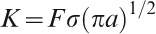
The crack growth kinetics of DHC is generally represented in terms of a plot of crack velocity versus stress intensity factor or V–K curve13 as shown schematically in Fig. 1, where V is crack growth velocity and K is the stress intensity factor that characterises the near tip stress field of a sharp crack in an elastic material subjected to an applied load σ. For a mode I crack, the stress intensity factor is given by62
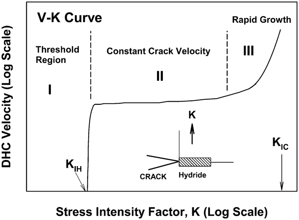
DHC velocity as a function of the Mode I stress intensity factor K, showing a growth threshold K IH, for the onset of DHC, a constant velocity region and a fast fracture region
The shape of the V–K curve reflects the underlying physical mechanisms associated with the DHC in zirconium alloy cladding. Current understandings of the physical mechanisms that are responsible for the various stages of DHC growth in zirconium alloys are reviewed to identify the role, if any, of DHC in the integrity of zirconium alloy cladding. In particular, assessing the current understandings on the origin of K IH and the factors affecting the DHC threshold, the crack growth kinetics and the onset of unstable fractures will be emphasised.
Threshold stress intensity factor K IH
DHC requires the diffusion of hydrogen to a highly stressed region, the precipitation of hydrides, and then the fracture of hydrides within the fracture process zone.5,13 The fracture toughness of zirconium hydrides 
Shi and Puls13 elucidated the theoretical value of K
IH for zirconium alloys by considering fracture initiation of hydrides formed ahead of a sharp crack tip and a shallow notch tip14 based on a local critical stress for hydride fracture. The local stress at the crack or notch tip was modelled by summing the contributions from the elastic stress field of a sharp crack or a notch and the compressive stress field induced by the volume change incurred during the precipitation of hydrides in a zirconium matrix with hydrogen in solid solution. The volume increases associated with the formation of the metastable face centred tetragonal hydride and the stable fcc hydride are 12% and 17% respectively.4 Figure 3a
illustrates the effects of hydride formation on the near tip stress field of a sharp crack after hydride formation in the crack tip process zone. The von Mises effective stress σ
eff computed from the crack tip elastic stress field, increases with decreasing distance from the crack tip, reaching a value equal to the yield stress σ
y of the matrix in the crack tip plastic zone. Within the crack tip plastic zone, the compressive hydride transformation stress σ
hydride is superimposed and summed with σ
eff to give the local stress σ
local normal to the crack tip hydride. The calculated local stress distributions for a crack tip with a hydride are shown for various K levels in Fig. 3b
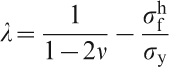
. The calculation by Shi and Puls13 showed that the local stress near the crack tip was compressive at low K levels [K<2 MPa m1/2 (1·82 ksi in.1/2)], but became tensile when K>4 MPa m1/2 (3·64 ksi in.1/2). Shi and Puls13 postulated that hydride fracture occurs only when the local stress in the hydride exceeds a critical value. The critical stress criterion for hydride fracture led to an expression for K
IH, which is given by Shi and Puls13


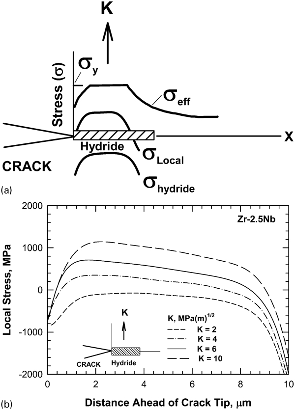
a Schematic showing crack tip hydride and stresses. b Profiles of σlocal = σeff+σhydride at crack tip for a hydride 2 μm (7·87×10−2 mil) thickness, 10 μm (0·39 mil) long and 10 μm (0·39 mil) wide under different K values. Results are from Shi and Puls13 (1 MPa = 0·145 ksi)
Comparison of theoretical K IH with experimental data. Data are from Shi and Puls13 (1 MPa m1/2 = 0·91 ksi in.1/2)
The effects of a compressive transformation stress field on the K
IH threshold can be modelled based on transformation toughening developed to explain the toughening resulting from the transformation of zirconia (ZrO2) from the tetragonal structure to the monoclinic structure near the crack tip region.65 In both zirconia and zirconium hydrides, the stress induced phase transformation results in a volume increase and a compressive stress field in the matrix that shields the crack tip from the applied tensile stress. This is illustrated in Fig. 5, which shows a Mode I crack subjected to a remotely applied stress (resulting in K) and a hydride formed at the crack tip. The local stress intensity at the crack tip K
tip is given by65
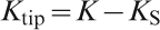


Crack tip shielding of a crack in an elastic field by the compressive transformation stresses accompanied by hydride formation at a crack tip
Pan et al.
66 utilised equations (5) and (7) and the pertinent material parameters for fcc zirconium hydrides, which are summarised in Table 1, to predict the K
S and K
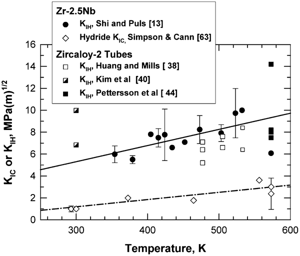
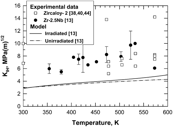
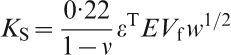
IH values for Zr–2·5Nb and Zircaloy-2 as a function of temperature. As shown in Fig. 6, the fracture toughness value of zirconium hydrides, taken from Simpson and Cann,63 ranges from 1 to 3 MPa m1/2 (0·91–2·73 ksi in.1/2) in the temperature range of 300–600 K (80·6–620·6°F). In contrast, the computed value of the shielding stress intensity factor K
S is −4·34 MPa m1/2 (−3·95 ksi in.1/2) at 300 K (80·6°F) and increases linearly with increasing temperature to −2·84 MPa m1/2 (−2·58 ksi in.1/2) at 600 K (620·6°F). The calculated K
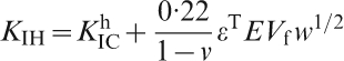
IH value, which is the sum of K
S and 

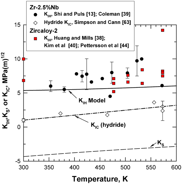
Theoretical values of K IH based on the fracture toughness K IC of hydrides (data are from Simpson and Cann63) and crack tip shielding of near tip stress intensity factor K S compared against experimental data of K IH from the literature (data are from Coleman,39 Shi and Puls,13 Huang and Mills,38 Pettersson et al. 44 and Kim et al. 40) {1 MPa m1/2 = 0·91 ksi in.1/2; T (°F) = 1·8 [T (K)–273]+32}
Material parameters in K IH model for Zr–2·5Nb and Zircaloy-2 (1 MPa = 0·145 ksi; 1 MPa m1/2 = 0·91 ksi in.1/2)
Because the K
IH threshold originates from crack tip shielding, the value of K
IH for DHC in zirconium based alloys is expected to vary with the crack length and exhibits different K
IH values for small and large cracks. In general, the K
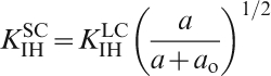
IH for small cracks is expected to have a lower value than that of large cracks because of a longer crack wake with greater crack-tip shielding. The growth threshold for small cracks 


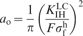
Comparisons of large crack and small crack threshold stresses for delayed hydride cracking in Zr–2·5Nb for K IH values of 5·38 MPa m1/2 (4·9 ksi in.1/2) and 12 MPa m1/2(10·9 ksi in.1/2). The threshold stresses for DHC approach the hydride fracture stress, which is 648 MPa (94 ksi) (data are from Shi and Puls17), at various crack lengths, depending on the K IH value. DHC growth occurs when the cladding stress exceeds the threshold stress at a given crack length. (1 MPa = 0·145 ksi; 1 MPa m1/2 = 0·91 ksi in.1/2; 1 μm = 0·0394 mil)
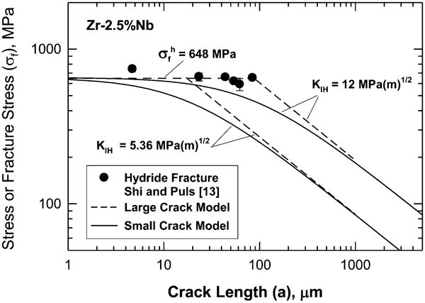
Using the appropriate a o for various K IH values at 300 and 600 K (80·6 and 620·6°F), equation (8) was used to calculate the K IH values for small cracks as a function of crack length, and the results are presented in Fig. 8. The results show that the K IH value for small cracks in zirconium alloys approaches a very small value at diminishing crack size. On the other hand, hydride fracture occurs only when the hydride length exceeds a critical length. Experimental data indicated that for Zr–2·5Nb, the critical hydride length is on the order of 10–20 μm (0·394–0·787 mil), and the hydride width is about 2 μm (7·87×10−2 mil) thick.69,70 These hydrides are formed ahead of a crack tip loaded at a stress intensity factor just below the K IH threshold.70 The crack front is not uniformly hydrided but occurs in a discontinuous, intermittent process or a narrow band of planes parallel to the crack growth plane.69 The smallest crack length for a in equation (8) is therefore about 10–20 μm (0·39–0·79 mil), leading to a lower bound K IH value of 3·26 and 4 MPa m1/2 (2·97 and 3·64 ksi in1/2) for critical crack lengths of 10 and 20 μm (0·39–0·79 mil) respectively. The K IH value increases with increasing crack length and asymptotically approaches the large crack K IH value, which is 5·36 MPa m1/2 (4·88 ksi in.1/2) at 300 K (80·6°F), but is 6·03 MPa m1/2 (5·48 ksi in.1/2) at 600 K (620·6°F).
Dependence of K IH on crack length for small cracks. For a crack depth of 10–20 μm (0·39–0·99 mil), K IH≈3·3–4 MPa m1/2 (3–3·64 ksi in.1/2), but its value increases rapidly with the crack length to saturate at the large crack threshold (1 MPa m1/2 = 0·92 ksi in.1/2; 1 μm = 0·0394 mil; 300 K = 80·6°F; 600 K = 620·6°F)
It appears that the critical hydride length significantly affects the DHC threshold for small cracks. The existence of a critical hydride length, which was assessed by Shi and Puls,41 has been attributed to a transition of the local stress in the hydride from compressive to tensile as the hydride lengthens. This relation is illustrated in Fig. 9, which shows the local stress at the tip of a crack with a hydride of length L subjected to a stress intensity factor of 10 MPa m1/2 (9·1 ksi in.1/2). The local stress is compressive when the hydride length is 2 μm (7·87×10−2 mil). The local stress becomes slightly tensile when the hydride lengthens to 3·3 μm (0·13 mil), and the local stress increases to above 1000 MPa (145 ksi) and exceeds the fracture strength [648 MPa (94 ksi)] of the hydride when L increases to 10 μm (0·394 mil). Furthermore, the local stress increases with increasing K values for a given hydride length. The results from Shi and Puls41 in Fig. 3b show that at L = 10 μm (0·394 mil), the local stress is compressive for K = 2 MPa m1/2 (1·82 ksi in.1/2), and a local tensile stress occurs at the crack tip only when K>4 MPa m1/2 (3·64 ksi in.1/2). Experimental evidence on Zr–2·5Nb69 – 71 and Zircaloy-237,38,44,45 supporting the concept of a critical hydride length includes (1) direct observations of the presence of intact hydrides at the crack tip stress intensity factor at or just below K IH in Zr–2·5Nb and (2) the observations of discrete striation spacings and hydride spacings associated with DHC in zirconium alloys.46,47 For Zr–2·5Nb, the critical hydride length is about 10–20 μm (0·394–0·787 mil),70 which was measured directly ahead of a crack tip loaded just below K IH. In many instances, a series of hydride platelets with a length on the order of 60–100 μm (2·36–3·94 mil) precipitated ahead of the crack tip during DHC in Zr–2·5Nb69 and Zircaloy-2.22,37,38,44,45 In both cases, the length of individual hydrides was about 10–15 μm (0·394–0·59 mil).22,38 These experimental observations suggested that a critical hydride length of 10–20 μm (0·394–0·79 mil) may apply to both Zr–2·5Nb and Zircaloy-2. In addition, the critical hydride length [10–20 μm (0·394–0·787 mil)] is essentially identical to the a o value. This implies that once a hydride crack forms, its crack length is almost within the continuum crack growth regime (a>a o); consequently, the small crack regime is fairly limited for DHC in zirconium alloys. Thus, the large crack threshold K IH values should be adequate for DHC in Zr–2·5Nb and Zircaloy-2. Figure 8 shows the minimum K IH value for small cracks in Zr–2·5Nb is calculated to be about 3·26–4 MPa m1/2 (2·97–3·64 ksi in.1/2) at about 10–20 μm (0·394–0·787mil). The K IH increases rapidly with crack extension and approaches that of the large crack K IH threshold after about 100–200 μm (3·94–7·87 mil) crack growth for the lower bound values of K IH = 5·36 MPa m1/2 (4·88 ksi in.1/2) at 300 K (80·6°F) and K IH = 6 MPa m1/2 (5·46 ksi in.1/2) at 625 K (665·6°F). For the upper bound K IH [ = 12 MPa m1/2 (10·9 ksi in.1/2)], the large crack threshold is not reached until after 1000 μm [39·4 mil] crack extension. The difference in the K IH values for small crack and large cracks gives rise to the resistance curve (R curve) behaviour that has been reported by Yan and Eadie70 and modelled by Jernkvist.72
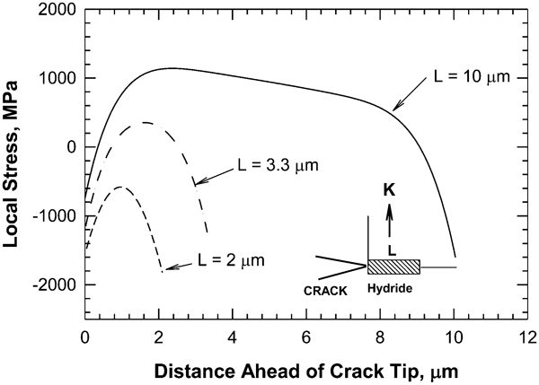
Profiles of σlocal = σeff+σhydride at crack tip for hydrides having different lengths under K = 10 MPa m1/2 (9·1 ksi in.1/2). Results are from Shi and Puls13 (1 MPa = 0·145 ksi; 1 μm = 0·0394 mil)
The difference between the experimentally measured large crack K IH threshold and the estimations of the K IH model shown in Fig. 6 is largely caused by the presence of additional toughening mechanisms that shield the crack tip stresses from the fracturing of the near tip hydrides. The toughening mechanisms responsible for increasing the K IH threshold in Zr based cladding are summarised in the following subsections.
Texture toughening
Zirconium hydrides are favoured to form on the {1017} crystalline planes, often referred to as hydride habit planes, which are orientated about 15° from the (0001) planes.40 This tendency results in a dependence of the K IH threshold value on the crystallographic texture in the zirconium alloy cladding in general and on the basal pole component in particular. Figure 10 shows the K IH threshold data38 – 40,73– 75 compiled by Kim et al. 40 as a function of volume fraction of the basal pole components. The lowest K IH threshold occurs in specimens with a strong basal texture and the maximum applied stress normal to the basal plane. Under these circumstances, many grains in the near-tip regions are oriented for the formation of fcc zirconium hydrides on the {1017} planes that are aligned normal to the maximum principal stress and can be fractured easily, thereby leading to a low K IH threshold. In contrast, non-basal grains in the near tip region form hydrides that are not oriented to the maximum principal stress and require a higher applied stress or stress intensity factor to cause hydride fracture at the crack tip, thereby enhancing the K IH value. Thus, crystallographic orientation or texture of zirconium grains significantly influences the K IH value for the onset of DHC.
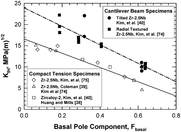
Threshold stress intensity factor K IH of Zr–2·5Nb tube with crack growth direction as a function of the basal pole components. Data are compiled by Kim et al. 40 (1 MPa m1/2 = 0·91 ksi in.1/2)
Ligament toughening by zirconium grains
Because not all grains ahead of the crack tip are optimally oriented for hydride formation and fracture on the {1017} planes, some grains in the near tip process zone might not form hydrides or may form hydrides on poorly oriented {1017} planes that result in a tortuous crack path. In both instances, the crack path can be bridged by zirconium grain ligaments that are more ductile and tougher than the fcc hydrides. This is a very powerful toughening mechanism, because the fracture toughness of the zirconium matrix can be as high as 58–70 MPa m1/2 (52·8–63·7 ksi in.1/2),76
–
80 compared to a K
IC close to 1 MPa m1/2 (0·91 ksi in.1/2) for the hydrides.63 The amount of toughening also increases with the bridging length.81
–
83 Furthermore, the toughening mechanism is operative in conjunction with transformation toughening. The increase in the K
IH threshold due to crack bridging by zirconium matrix ligaments can be estimated on the basis of the micromechanical model developed for treating ductile phase toughened materials, which is given by Chan and Davidson84


Hydrogen content
The value of K IH for DHC at a given temperature is dependent on the hydrogen content. Figure 11 shows that the K IH value decreases with increasing hydrogen contents for Zr–2·5Nb at 250°C (482°F),41 and the theoretical curves indicate that in Shi and Puls’s analysis,41 crack tip hydride length must exceed a critical length for hydride cracking to occur, and the maximum length a hydride can attain depends on the hydrogen content in solution. As a result, the K IH increases with decreasing hydrogen content in solution.
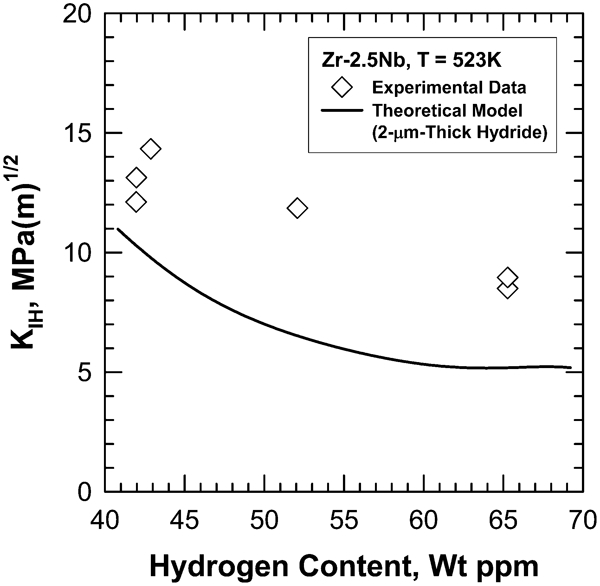
The threshold stress intensity factor K IH as a function of hydrogen concentration in solid solution. Experimental data and theoretical model are from Shi and Puls41 (1 MPa m1/2 = 0·91 ksi in.1/2; 523 K = 482°F; 2 μm = 0·0787 mil)
The dependence of the critical hydrogen content for the onset of hydride cracking in Zr–2·5Nb is shown as a function of temperature in Fig. 12.7 The critical hydrogen content for crack initiation is larger than the hydrogen solubility limit for hydride dissolution (TSSD), but is less that that for hydride precipitation (TSSP) at a given temperature. For a given hydrogen content, DHC cannot occur at a temperature higher than TSSD because no hydrides can form, even at the crack tip. DHC occurs at a small undercooling below the TSSD, and there is a large hysteresis between the TSSP and TSSD for hydrogen in zirconium. The hysteresis, which is caused by the volume expansion during TSSP, results in different DHC behaviours during heating and cooling of zirconium alloys, as well as variations with hydrogen contents.7 The terminal solid solubility of hydrogen in Zircaloy-2 was measured by McMinn et al. 86 Schofield et al. 87 recently showed that the critical temperatures for the onset and the arrest of DHC in Zircaloy-2 fall below the dissolution solvus temperature and above the precipitation solvus temperature, in accordance with experimental findings for Zr–2·5Nb.7
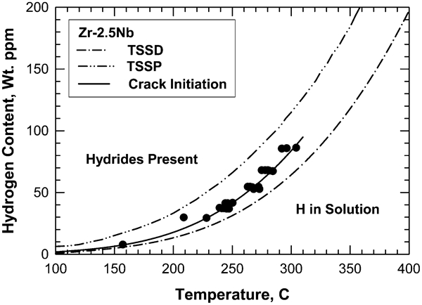
Terminal solubility limits for zirconium: TSSD hydride dissolution limit, TSSP hydride precipitation limit and crack initiation temperature. Results are from Sagat and Puls7 {T (°F) = 1·8[T (K)–273]+32}
Irradiation effects
Irradiation appears to exert only a small effect on the K IH value of Zr–2·5Nb tested at 130–350°C (266–662°F). Sagat et al. 43 reported a small decrease in K IH as the fluence increased to about 1×1025 n m−2 (1·08×1026 n ft−2) for fast neutrons with energy above 1 MeV at an irradiation temperature in the range of 250–290°C (482–554°F), but no increase upon further increase in fluence up to 8×1025 n m−2 (8·61×1026 n ft−2), as shown in Fig. 13. The temperature corresponding to the data shown in Figure 13 was not reported by Sagat et al.,43 but K IH testing was conducted at 130–350°C (266–662°F). The average K IH was 7·5±1·3 MPa m1/2 (6·82±1·18 ksi in.1/2) for the unirradiated materials compared to 6·2±0·9 MPa m1/2 (5·64±0·82 ksi in.1/2) for the irradiated materials at the 95% confidence level. Similarly, the K IH value for unirradiated Zircaloy-2 ranges from 7·5 to 13·8 MPa m1/2 (6·87±1·18 ksi in.1/2) for 200–300°C (392–572°F), while it ranges from 9·9 to 12·7 MPa m1/2 (9–11·6 ksi in.1/2) in the irradiated materials at 200–300°C (392–572°F).37,44 These results suggest that the K IH value at high fluence (8×1025 n m−2) (8·61×1026 n ft−2] might be used as a lower bound K IH for irradiated Zircaloy-2 or Zircaloy-4.
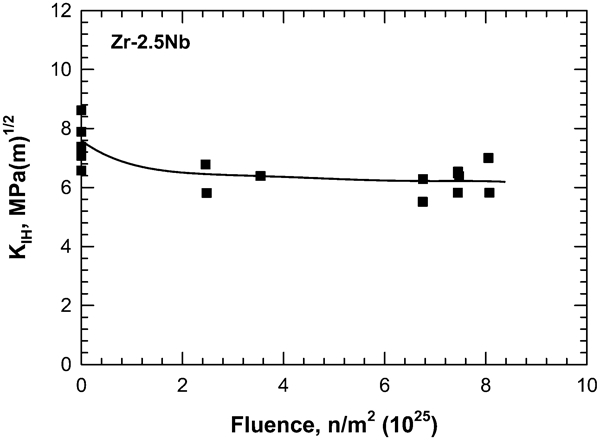
Dependence of K IH on irradiation fluence. Data are from Sagat et al. 43 (1 MPa m1/2 = 0·91 ksi in.1/2; 1 n m−2 = 10·8 n ft−2)
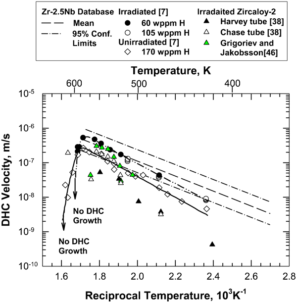
Temperature dependence of DHC
Although it has a minimal effect of a factor of 2 on the K
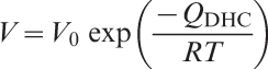
IH threshold, temperature exerts significant influence on the growth kinetics of DHC in zirconium based alloys. Figure 14 summarises the complex relationships between crack velocity and reciprocal temperature observed in Zr–2·5Nb7 for Zircaloy-2 cladding tubes.38,46 At temperatures below 318°C (604°F) or the TSSP, DHC velocity V, is dictated by the diffusion of hydrogen to the crack tip to form hydrides and is related to the absolute temperature according to the Arrhenius relation given by12,38


Material parameters used in DHC computation of time to failure as function of temperature
It is evident that there are two competing mechanisms that control the dependence of DHC velocity on temperature: TSSD and TSSP.7 Figure 12 shows the TSSD and the TSSP for Zr–2·5Nb. The increase in DHC velocity with decreasing temperature below TSSD is controlled by hydrogen solubility limit and hydride formation beyond the critical size. In this regime, the temperature is sufficiently high, and hydrogen diffusion to the crack tip occurs quickly; a lower temperature provides a higher driving force for TSSP where fracture at the crack tip results in a higher DHC velocity. At temperatures below about 318°C (604°F), the DHC velocity decreases with decreasing temperature because of a lower hydrogen diffusivity and a longer time for hydrogen to move from the bulk to the crack tip. The DHC velocity exhibits a maximum value at about a critical temperature T C, which is 318°C (604°F) for Zr–2·5Nb, where the precipitation and diffusion kinetics are optimum. The critical temperature at which the maximum DHC velocity occurs is about 30–40°C (54–72°F) below the TSSD.7 Limited experimental data indicated that the critical temperature T C ranges from 310 to 320°C (590–608°F) and is not sensitive to hydrogen content in the range of 60–170 wt ppm.7
For DHC at a constant temperature, the time to failure t
f can be obtained as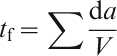
Computed time to leakage based on crack depth equal cladding wall thickness compared against computed time to fracture based on the stress intensity factor exceeding a critical stress intensity factor of 70 MPa m1/2 (63·7 ksi in.1/2) (1 mm = 39·4 mil)
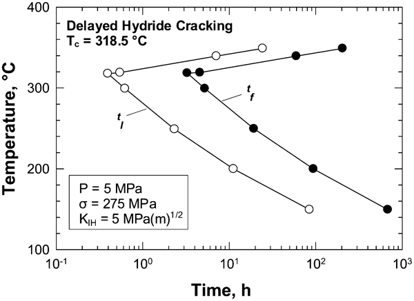
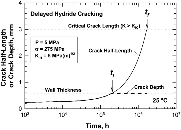
Computed time to leakage (crack depth = wall thickness) and time to fracture K>K IC) by DHC in Zr–2·5Nb as a function of temperature. The results show the time to failure (leakage or fracture) decreases with increasing temperature from 0 to 320°C (32–608°F) and increases from 320 to 350°C (608–662°F). No DHC failure occurs at temperatures above 350°C (662°F) because of the absence of hydride formation at the crack tip [T (°F) = 1·8T (°C)+32; 1 MPa m1/2 = 0·91 ksi in.1/2]
Texture effects
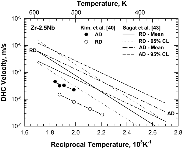
The DHC velocity at a given stress intensity factor K exhibits an orientation dependence. Results on Zr–2·5Nb showed that the DHC velocity in the longitudinal or axial direction of the cladding is higher than that in the radial direction, as shown in Fig. 17 for various temperatures.40,43 There is, however, a discrepancy in the reported activation energies for the longitudinal and radial directions. Sagat et al. 43 reported that the temperature dependency of DHC velocity and the activation energy in the longitudinal (axial) direction are smaller than those in the radial direction. On the other hand, the results by Kim et al. 40 indicated similar activation energy values but lower DHC velocity values in both the longitudinal and radial directions than those reported by Sagat et al. 43
Effects of irradiation on DHC
The effects of irradiation on the DHC velocity in Zr–2·5Nb have been investigated by Sagat and Puls.7 An ex-service pressure tube that had been irradiated at about 295°C (563°F) to a neutron fluence of approximately 7×1025 n m−2 (7·54×1026 n ft−2] (E>1 MeV) was used for the study by hydrogen charging to 60 and 105 wt ppm. For comparison, an as-manufactured pressure tube was hydrogen charged and homogenised at 400°C (752°F) to obtain 170 wt ppm hydrogen. The DHC velocity measurements were performed at 295–345°C (563–651°F) under an initial K I of 15–17 MPa m1/2 (13·65–15·47 ksi in.1/2), which increased to about 23 MPa m1/2 (20·93 ksi in.1/2) during subsequent crack growth. Figure 14 shows the DHC velocity for irradiated material compared against a database of axial crack velocity obtained using CANDU ex-service irradiated pressure tubes.7 The two sets of the DHC data, as shown in Fig. 14, show slightly different slopes and activation energy values. Figure 14 also shows that the DHC data for the unirradiated materials are slightly lower than those of the irradiated material at a given temperature. For both materials, the maximum DHC velocity occurs at about 310–320°C (<590–608°F), and DHC ceases to occur at temperatures above 350°C (662°F). Sagat el al. 43 also measured the DHC velocity and K IH in Zr–2·5Nb that were irradiated at temperatures in the range of 250–290°C (482–554°F) in fast neutrons with a high energy (E>1 MeV) and fluxes between 1·6×1017 and 1·8×1018 n m−2 s−1 (1·72×1018 and 1·94×1019 n ft−2 s−1) to fluences between 0·01×1025 and 9·8×1025 n m−2 (1·08×1024 and 1·06×1027 n ft−2). Their results indicated that these levels of neutron irradiation reduced K IH by about 20%43 and increased the DHC velocity by a factor of five.7,43
Crack size distributions in zirconium cladding
Cracks in zirconium alloy cladding can originate from several possible sources, including (1) initial manufacturing defects, (2) the oxide layer on the outer wall, (3) the hydride layer or rim on the outer wall surface and (4) corrosion-induced cracks on the inner wall surfaces.16,19 – 21,26– 36
DOE estimates of the manufacturing defect size distribution in Zr cladding indicated that the crack depth may be described using an exponential distribution with a median (50%) crack depth of about 12 μm (0·47 mil).48 The exponential shape distribution was justified based on manufacturing defect surveys made by Sanders et al.,88 while the median crack depth and the constants in the exponential shape function were deduced based on a review of PWR fuel performance that indicated there were 485 fuel assembly failures in 16 153 assemblies over a 5 year period for which data were available. Of the 485 fuel assemblies, 240 failures were caused by external events such as handling, debris, and grid fretting. The remaining 245 failures, which were assumed to be caused by initial cladding cracks that were at least 28% through wall or 160 μm (6·3 mil) deep, were used to estimate the possibility of pin failure, the initial defect size distribution and a median (50%) initial defect size of 12 μm (0·47 mil).
The outer surfaces of the fuel rods are oxidised to form zirconium oxide and produce hydrogen as the fuel is irradiated in the reactor. As a result, the oxide thickness on the Zircaloy-4 PWR cladding tubes increases with increasing burnup.89 In particular, the maximum oxide thickness can be described in terms of a quadratic equation of burnup, reaching about 80–100 μm (3·15–3·94 mil) in Zircaloy-4 cladding tubes for a burnup of 60 GWd MTU−1.89 Analysis of the oxide thickness at a given level of burnup indicates that the oxide thickness in Zircaloy-4 cladding tubes follows a normal or lognormal distribution.66 For ZrO2, the fracture toughness is about 2·6 MPa m1/2 (2·37 ksiin.1/2).90 Fracture of the ZrO2 layer can produce a maximum crack depth of about 120 μm (4·73 mil) in high burnup fuel rod Zircaloy-4 cladding, and the corresponding crack size distribution would likely be normal or lognormal.
Hydrogen is produced and absorbed into the cladding as the outer cladding surface is oxidised.27,47,48 The location of maximum hydrogen content corresponds to the location where the peak oxide layer occurs.48 The hydrogen content is the highest at the outer surface and decreases toward the centre. At the peak oxide location, the region of enriched hydrogen content can extend more than 100 μm (3·94 mil) from the outer surface.25 For fuel rods discharged with burnup of 45–50 GWd MTU−1, the amount of hydrogen collected at the outer surface exceeds the saturation limit, and as much as 120 ppm hydrogen is available for hydride formation in the form of radial hydrides or hydride blisters23 when the cladding tubes are cooled from 350 to 45°C (662–113°F). Because the fracture toughness of zirconium hydride [1–3 MPa m−1/2(0·91–2·73 ksi in.1/2)] is slightly less than that of zirconium oxide [≧2·6 MPa m−1/2 (2·37 ksi in.1/2)], cracking of the oxide layer at the maximum thickness location is likely to be followed by fracture of the hydride layer or hydride blister below the oxide layer.23 Under this circumstance, the maximum crack length in the fuel rod cladding would be on the order of 200 μm (7·87 mil). Its subsequent growth by DHC if it occurs could lead to rod failure.23 Detailed descriptions of cladding failure resulting from crack initiation at the outside wall are available in the literature.21,25,27,36 Because of reduced corrosion and hydrogen pickup, a recent zirconium alloy (M5) is expected to exhibit smaller crack sizes resulting from oxide cracking or hydride blister fracture, compared to Zircaloy-2 and Zircaloy-4.
A structural integrity assessment of pressure tubes in CANDU reactors operating in South Korea was made by Park et al.,11 who inspected 44 pressure tubes after 19 years of operation. For all the surveyed Zr–2·5Nb cladding tubes, 8% were affected by flaws greater than those allowable by code [>150 μm (5·91 mil) depth] and about 60% were damaged by debris.11 In addition, 30% of the inspected pressure tubes contacted the calandria tubes, even though no hydride blister was found in any of the tubes. The major cause of flaws was notch-like shaped debris defects that intensified stresses at the notch root and showed propensity to hydride formation and DHC.11
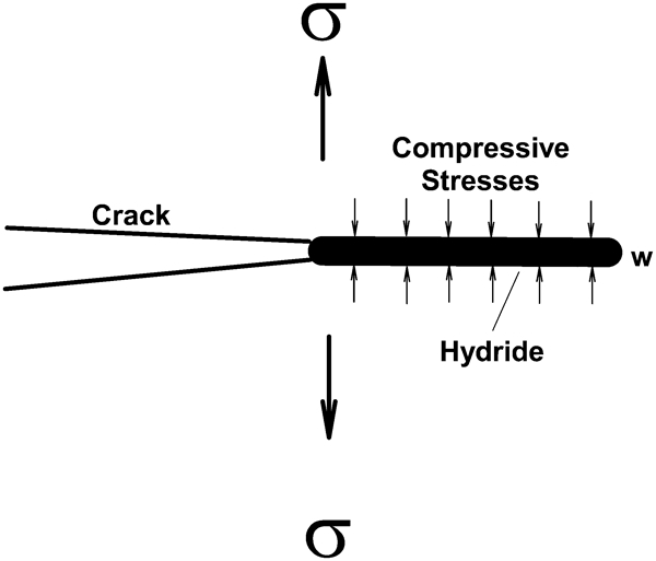
High burnup fuel cladding under power ramping conditions is exposed to locally enhanced residual and PCMI stresses not only at high temperatures, but also during subsequent slow cooling in the reactor. Under certain power ramp conditions, PCI can lead to high local cladding stresses and iodine induced SCC,91 which has led to the use of a sponge zirconium liner or low friction coating in the inner wall of the fuel cladding for BWR as a remedial measure to prevent PCI failure.17 The presence of these high local stresses can cause significant amounts of radial hydrides to form in local regions, sometimes leading to a pseudocleavage fracture known as RHA-DHC.25,36 This type of DHC has been reported to initiate from the outside walls of Zircaloy-2 BWR fuel cladding tested under power ramp and hold conditions with and without a primary defect.21,25,27,36 According to Chung,25 inner wall cracks consistent with RHA-DHC are suspected to have occurred in a high burnup Zircaloy-4 PWR fuel during simulated RIA-like testing in a CABRI reactor (REP-Na1). Numerous cracks initiated from the inner diameter and propagated towards the outer diameter at significant depth. Figure 18 shows the axial distribution and depth of the inner wall cracks in the failed fuel cladding of REP-Na1. The crack depth ranged from 10 to 480 μm (0·39–18·9 mil),25 and its distribution can be described in terms of a normal or log-normal distribution.66 Many of the crack surfaces exhibited a brittle pseudocleavage appearance and sometimes were decorated with hydride debris, suggesting the DHC might have been the crack growth mechanism that caused cladding failure. Ramp testing of segmented fuel rods by Hayashi et al. 36 clearly showed that the failure mechanism in higher burnup (56–61 GWd MTU−1) segment rods is no longer one of pinhole perforation as observed in low burnup (<43 GWd MTU−1), but a RHA-DHC process resulting from a combination of high PCMI stresses and radially oriented hydrides precipitated at the outer rim during ramp testing. The high PCMI stresses produce a variety of hydride microstructures in high burnup fuel rods that are susceptible to RHA-DHC under in-reactor and ex-reactor conditions, because the hydrided microstructure is retained in the cladding. Hayashi et al. reported interface bonding between pellets and cladding tubes,36 which may retain parts of the PCMI stresses after cooling. In many cases, the PCMI stresses are sufficiently high to initiate RHA-DHC and propagate the crack to cause axial fracture in single step ramp tests, as reported by Hayashi et al. 36 It was also considered that stress could be relieved by circumferential cracks at the cladding and the fuels. These potential in-reactor failure mechanisms in high burnup cladding tubes are schematically illustrated in Fig. 19, which includes (1) oxidation of the outer wall surface and oxide cracking, (2) formation of a hydride blister beneath the zirconium oxide layer and blister cracking, (3) radial hydride formation ahead of the hydride blister due to hydride growth or hydride reorientation, (4) uniform corrosion of the inner wall surface and cracking of the corrosion products (predominantly oxides) and (5) DHC. The first four fracture mechanisms serve as the crack initiation processes at the outer and inner walls of the cladding. Once initiated, the outer wall and inner wall cracks can grow by DHC if the stress intensity factor exceeds the K IH growth threshold.
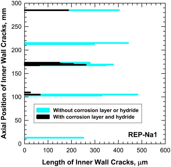
Axial position versus length of inner wall cracks observed in REP-Nal. Data are from Chung25 (1 mm = 39·4 mil; 1 μm = 0·0394 mil)
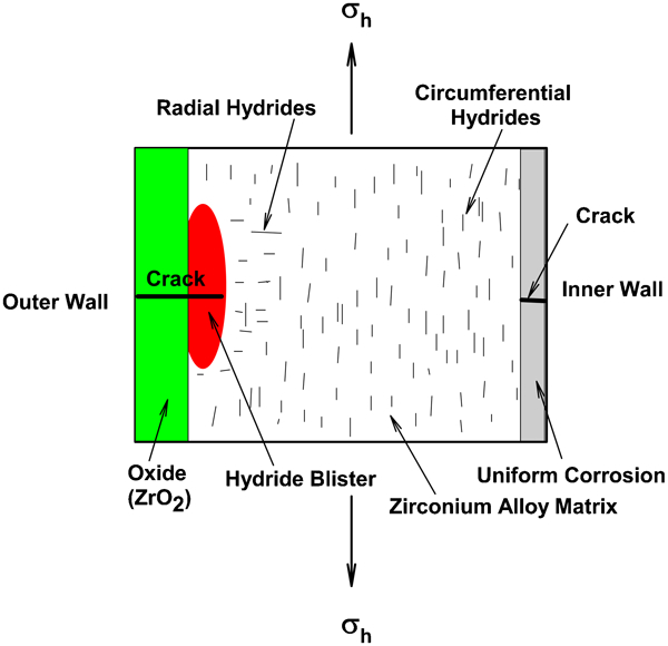
Summary of possible failure mechanisms in high burnup Zr based fuel cladding tubes, showing (1) oxide formation and cracking on outer wall, (2) hydride blister formation and cracking, (3) hydride reorientation and (4) uniform corrosion on the inner wall. Once initiated, the outer wall and inner wall cracks can propagate by DHC if K>K IH. Schematic corresponds to a cross section of the cladding perpendicular to the axial direction where σh denotes hoop stress
DHC has been a concern for CANDU reactors. Operators of CANDU reactors in Canada10 and Korea2 have implemented (1) inspection and survey procedures for detecting defects and hydride initiated cracks in pressure tubes and (2) a fracture mechanics methodology and a leak before break requirement for predicting the pressure tube failure resulting from DHC. A multinational program for characterising DHC growth kinetics of Zr–2·5Nb in nuclear reactors of pressure tubes was conducted under the auspices of the IAEA.15
The causes and mitigation methods for fuel failure in BWRs were reviewed in an IAEA Technical Meeting.18 Kim23 reported that primary and secondary hydriding in Zircaloy-2 cladding played critical roles in recent failures of nuclear fuel rods in Korean BWR power plants. The roles of hydrides in these rod failures are similar to those reported by several investigators,16,19 – 22 as summarised earlier in the section on ‘Introduction’. The multitude of field evidence indicates that DHC has occurred in pressure and cladding tubes during power operations, even though its occurrence might not always lead to rod fracture, because (1) a low friction coating or a sponge–zirconium liner is used between pellets and cladding,15 (2) an early detection and intervention program has succeeded2 and (3) the transient stresses that drive DHC in cladding tubes occur only during off-normal conditions. However, Hayashi et al. 36 recently observed hydrided induced failure in Zircaloy-2 cladding during ramp tests of high burnup BWR segment rods ranging from 43 to 61 GWd MTU−1. At high burnups (56 and 61 GWd MTU−1), the segmented rods failed by a RHA-DHC process in Zircaloy-2 cladding tubes during single step ramp tests. This failure mechanism, which was attributed to high PCMI stresses and hydrogen contents at high burnup, may potentially limit high burnup operation in BWRs,18 because the high PCMI stresses can produce a variety of hydrided microstructures that are susceptible to hydride fracture and DHC under subsequent tensile loading during service. The cladding stress that is responsible for DHC during service in the reactor or subsequent spent fuel environment is explored in detail in the next section.
Cladding stresses
The cladding stress under normal in-reactor conditions arises mainly from the internal gas pressure inside the cladding tubes. While the gas pressure increases with burnup and fission gas release fraction, there is a general consensus that the cladding stress due to internal gas pressure is sufficiently low that the growth threshold for DHC K IH would not be exceeded unless the cladding tube contained a deep crack.27,47,49,50 On the other hand, the transient stresses encountered in the cladding resulting from interaction with the fuel during in-reactor power ramps can be sufficiently high that they are likely to instigate DHC and could well lead to cladding failure under certain circumstances. The next section summarises the current status of cladding stresses computation arising from gas pressure and PCMI.
Gas pressure
The cladding stress depends on the temperature and quantity of fission gases in the plenum, which in turn depends on the burnup and fission gas release fraction. The hoop stress in cladding was computed on the basis of the thin wall approximation for a burnup ranging from 25–60 GWd MTU−1 and plenum pressure ranging from 3·41 to 5·51 MPa (0·5–0·8 ksi). The gas pressure P of fission gas and helium is given by48

Pellet–cladding mechanical interaction
The cladding stresses due to fission gas release are relatively low under normal conditions. During power ramp, the cladding stress increases because of mechanical interaction between the fuel pellets and the cladding (Fig. 20). The mechanism of PCMI, which is well established,91 results from the thermal expansion and crack induced volumetric increase of the fuel pellets during thermal transients. The thermal stresses lead to fuel fragmentation and increases in the pellet diameter. Creep of the cladding results in local ridges in the cladding tube as the fuel pellets change to an ‘hourglass’ shape.54 Early analyses of the PCMI stresses were reviewed by Cox,91 who concluded that stresses generated by PCMI during in-reactor power ramp are high, and the corresponding stress intensity factors are comparable to those measured in the laboratory. The stress concentration factors at cladding tube ridges were computed by Ranjan et al. 93 using an elastic axisymmetric shell analysis of the cladding by an asymptotic expansion method that yielded closed form solutions. Elastic concentration factors on the order of 1·1–2·8 were obtained for the circumferential stresses at the ridges, depending on the ridge height and the strain state developed at the ridge.
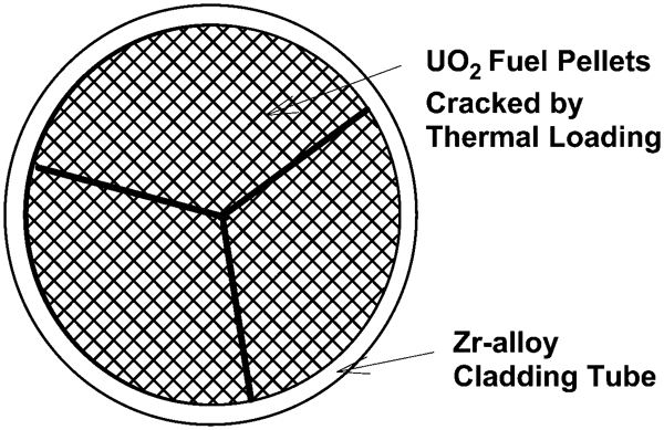
Pellet–cladding mechanical interaction results from the thermal expansion and cracking of the UO2 fuel pellets during power ramp and induces local tensile hoop stresses in the cladding that can potentially propagate an existing crack or defect by DHC
Recent PCMI analyses are elastic–plastic analyses based on FEM with complex constitutive models that include treatment of plasticity, creep, stress relaxation and irradiation effects.53 – 61 These FEM analyses are typically two-dimensional (2D) analyses. More recent 3D FEM analyses provided better descriptions of the time dependent evolution of the local transient stresses at various locations in the cladding tubes during power ramp including various hold times at the ramp terminal level.
Using an elastic–viscoplastic constitutive model that treats plasticity, creep, stress relaxation, anisotropic and irradiation effects, Schäffler et al. 57 computed the cladding stresses in a Zircaloy-4 cladding tube during a PWR power ramp transient using simulated loading conditions by imposing a circumferential strain rate of 2×10⁻⁵ s−1 followed by a relaxation period. Figure 21a shows the computed hoop stress in the cladding compared to the corresponding biaxial tensile tests at 350°C (662°F). The cladding reaches as high as 600 MPa (87 ksi), but decreases quickly in the first 20 min and saturates to about 410–450 MPa (59·5–65·3 ksi) after 100 min into the relaxation or strain hold period. This stress transient will be referred to as Type I, which is characterised by a stable, relaxed stress that is higher than that required to meet K>K IH and cause DHC.
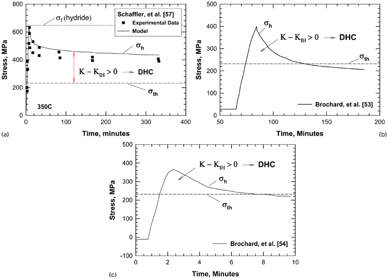
Stress transients associated with pellet–cladding mechanical interactions: a Type I stress transient with a stabilised stress that leads to K>K IH and DHC, b Type II stress transient with a peak stress that leads to K>K IH and DHC over a short duration (130 min) and stabilised stress that results in K<K IH and crack arrest and c Type II stress transient with a 7 min duration where K>K IH and DHC growth can occur (1 MPa = 0·145 ksi)
Suzuki and Uetsuka58 developed a fuel performance code, FEMAXI-6, for analysing light water reactor fuel rod behaviours in normal and transient conditions. The FEM based code, which has incorporated thermal and mechanical models for treating thermal conductivity degradation and pellet–clad bonding in high burnup fuel rods, analyses the PCMI stresses induced by swelling in high burnup BWR type fuel rods. Their calculations indicated that the cladding hoop stress transient during a power ramp showed a peak stress of 350 MPa (50·8 ksi), which relaxed quickly and became stable at 260–300 MPa (37·7–43·5 ksi) over a time period of about 120 min. The corresponding cladding temperature was 676 K (712·4°F) at the inner surface and 598 K (572°F) at the outer surface during the ramp. Bonding between the clad and pellets increased the hoop stress by 17% and also increased the biaxial stress state. Suzuki and Uetsuka58 also reported that the peak value in the stress transient was sensitive to the creep model chosen for the stress analysis. A hoop stress as high as 600 MPa (87 ksi) had been obtained depending on the creep model. The results of Suzuki and Uetsuka58 are thus comparable to those reported by Schäffler et al.,57 both in the transient stress levels and the length of the relaxation period.
Using the FEM code TOUTATIS, Brochard et al. 53 computed and reported the cladding stresses for a rod irradiated for two annual PWR operating cycles and subjected to a power increase from 240 to 450 W cm−1 (94·1–177·2 W in.−1) in about 20 min with a hold time of 100 min at the ramp terminal level. The transient inner clad hoop stress during the power ramp is presented in Fig. 21b . The shape of the stress evolution curve is similar to that shown in Fig. 21a , but the stresses are lower. The time period over which the transient stress persists is shorter and lasts for 100 min, which corresponds to the hold time at the ramp terminal level.
More recently, Brochard et al. 54 computed the cladding stresses for a rod irradiated for two annual PWR operating cycles and subjected to a power increase from 200 to 450 W cm−1 (78·7–177·2 W in.−1) in 2·5 min with an unspecified hold time at the ramp terminal level. Their results for the cladding circumference stress at the interpellet level, which are shown in Fig. 21c , indicate that the cladding stress is fairly low at the initial stage of the power ramp when the gap still exists between the fuel pellets and the cladding tube. The cladding stress builds up quickly once the gap between cladding and pellets closes under the combined effect of cladding creep and pellet swelling.54 The cladding circumferential stress reaches a maximum value of 350 MPa (50·8 ksi) and then decreases quickly to a lower value of 210 MPa (30·5 ksi) after 7 min at the ramp terminal level. For this case, the stress concentration factor at the cladding is about 1·34–1·43 based on experimentally measured values of 0·4–0·6 for the coefficient of friction between pellet and cladding. The stress transients shown in Fig. 21b and c will be referred to as Type II. In contrast to the Type I stress transient, Type II meets the condition of K>K IH for only a short time. Relaxation of the local stress occurs quickly, and the stabilised stress is below that required to exceed K IH; therefore, Type II transients lead to intermittent crack growth and crack arrest.
The magnitude and the duration of the transient PCMI stress are sensitive to a number of factors,53,54,59 including (1) pellet geometry such as pellet shape, the height to diameter ratio, fuel swelling and pellet fragmentation; (2) thermomechanical loading history during power ramp and the duration of hold time at the ramp terminal level; (3) modelling assumptions such as the axial constraint and the constitutive model utilised to treat time and temperature dependent inelastic flow resulting from plasticity, creep, stress relaxation, swelling and irradiation effects; and (4) cladding characteristics and material parameters such as wall thickness, thermal properties, elastic–viscoplastic properties, pellet–pellet friction and the coefficient of friction at the fuel cladding interface that are used in the computation.
Systematic studies of the sensitivity of the PCMI stress to structural and material parameters were performed by Brochard et al.,53,54 who identified the axial constraint, the pellet height, the pellet fragmentation and the hollow pellet as important variables affecting the PCMI stress. Retel et al. 59 evaluated the separate influences of structural and materials parameter variability on the PCMI in a fuel rod subjected to two PWR cycles with a power equal to about 200 W cm−1 (78·7 W in.−1) followed by a power transient with a maximum power equal to 412 W cm−1 (162·2 W in.−1). In the 3D FEM simulations of this set of baseline ramping conditions, the number of axial and radial pellet cracks, pellet fragment size, relative fragment displacement, degrees of symmetry in the fragment configuration, pellet–pellet friction and pellet–cladding friction were varied systematically. Among these six parameters, Retel et al. 59 found that the pellet–cladding friction coefficient and the number of axial pellet cracks are the most important in increasing the cladding stress. The maximum cladding stress obtained by Retel et al. 59 was in the range of 300–400 MPa (43·5–58 ksi) for a pellet–cladding friction coefficient of 0–0·2, with cladding temperatures of 440°C (824°F) and 366°C (691°F) at inner and outer cladding walls respectively.
Because of the large number of structural and material variables involved, it is difficult to assess the validity of the computed PCMI transient stress from a particular computation unless the computational results are verified by relevant experimental data. Bourreau et al. 56 performed power ramp tests on PWR fuel rods with fuel segments extracted from the same fuel rod. Designed by Connectors International, the original segmented fuel rod contained UO2 pellets that were initially enriched up to 4·5% in 235U and irradiated during two cycles in a 900 MW PWR to reach an average burnup of 23·8 GWd MTU−1. Three segments of the original fuel rod were extracted, refabricated into subrods and used in subsequent power ramp tests with four different ramp power histories and hold times at the maximum power or terminal ramp level (TRL). The hold times at the TRL were 0 s (no hold time), 16·5 min and 12 h 19 min. Cladding deformations were measured during the power ramping, and the power ramp tests were modelled using 2D and 3D fuel modelling codes. The experimental results of cladding deformation were correlated with power density and compared against FEM computations. The experimental results indicated that the hold time at the TRL exerted a significant effect on the cladding deformation and stresses in the power ramp tests. For all ramp tests, no rod failure occurred during or after the power ramp experiments. A good correlation was observed between the local power during irradiation and the cladding deformation measured after the ramp tests. Comparisons of post-irradiation measurements performed on the three tubes indicated that the cladding deformation increased with the hold time at TRL. The hold time particularly affected the evolution of secondary ridges. Many features of the power ramp tests, such as the axial power profile on cladding diameter variations during the power transients, were simulated by the provided FEM codes that the analysis used for pre-existing oxide fragmentation. In Bourreau et al.,56 2D modelling satisfactorily reproduced cladding diameter changes off ridges, while 3D modelling correctly simulated primary ridge changes and allowed secondary ridge buildup.
Direct evidence for the presence of a high PCMI stress was provided by the power ramp testing of BWR segmented rods conducted by Hayashi et al. 36 BWR 8×8 fuel assemblies with segmented rods of Zircaloy-2 cladding tubes were irradiated up to five cycles. Ramp tests of 25 segments with burnup ranging from 43 to 61 GWD MTU−1 were then conducted in a test reactor. One segment rod irradiated for three cycles (43 GWd MTU−1) failed by a single step ramp test after 9 min at a terminal ramp power of 614 W cm−1 with a pinhole caused by PCI and SCC. One segment rod irradiated for four cycles (56 GWd MTU−1) failed by a single step ramp test after 149 min at 551 W cm−1 with an outer side axial crack. Nine segment rods were irradiated for five cycles (61 GWd MTU−1). Two of these rods failed by a single step ramp test after 68–100 min at about 421–428 W cm−1, and one failed by a stair ramp test at 446 W cm−1, all with outer axial cracks. According to Hayashi et al.,36 the increase in hydrogen contents and PCMI stresses with increasing burnups led to the formation of radial hydrides at the outer rim and a change in the operative failure mechanisms in the cladding tubes. Specifically, the failure mechanism in the segment rods was PCI/SCC at low burnups (<43 GWd MTU−1). At high burnups (56 and 62 GWD MTU−1), rod failure was caused by a combination of high PCMI stresses and radial hydride assisted DHC growth during ramp tests. Cladding cracks initiated by fracture of radial hydrides at the outer rim and propagated inward by DHC to the inside wall, followed by DHC in the axial directions and finally ductile fracture. Post-test examination of the pellet–cladding interface revealed a bonding layer formed between the pellet and the cladding by mutual diffusion of UO2 and ZrO2.36 The observed times to rod failure in the power ramp tests ranged from 9 to 149 min, which are consistent with the durations (7–130 min) of PCMI transient stresses predicted by Brochard et al. 53,54
It is well known that the presence of a large tensile hoop stress during TSSP would align the hydrides along the radial direction of the cladding tube, forming radial hydrides. At certain temperatures, circumferential hydrides in zirconium cladding tubes can reorient under a tensile hoop stress to form radial hydride, providing that the tensile stress exceeds the critical stress for hydride reorientation. Experimental data of the critical stress for hydride reorientation were reviewed by Chung,25 and additional data needs in this area were discussed by Einziger et al. 94 Previously, Chung25 determined empirically that the critical tensile for hydride reorientation is about 100 MPa and its value is relatively insensitive to temperature, as shown in Fig. 22. Subsequently, Ferry and Poinssot95 suggested that the critical stress for hydride reorientation may not be a constant, but its value may increase with decreasing temperature, as shown in Fig. 22. More recently, Chu et al. 96 presented a theoretical analysis that showed the threshold stress for hydride reorientation decreases with increasing temperature and hydrogen content in a complex manner. The results for Zircaloy-4 with 200 wt ppm H2 are shown in Fig. 22. Daum et al. 97 recently reported that the critical stresses for hydride reorientation of non-irradiated and high burnup Zircaloy-2 are 80±10 and 75±10 MPa respectively. A comparison of the threshold stress boundaries against all of the available experimental data in Fig. 22 indicates that Chung’s empirical threshold stress boundary gives the best agreement, even though a few data points at temperatures of hydride reorientation at temperatures ≧400°C fall below the threshold line. The temperature during in-reactor power ramp is in the range of 300–350°C. Figure 22 shows that hydride reorientation would not occur at temperatures less than 400°C when the cladding stress is below the 90 MPa limit.94 At temperatures ≧400°C, hydride reorientation may occur at stresses below the 90 MPa stress limit, but more experimental data are needed.94 On the other hand, the PCMI transient stresses during in-reactor power ramps are in the range of 200–600 MPa. The high PCMI stresses are sufficiently high to cause hydride reorientation in the cladding tubes. A variety of hydride microstructures have been reported, including hydride blisters, hydride rims, sunburst hydrides and radial hydrides.16,19 – 21,26– 36 Once formed during power ramps, the hydride microstructures may remain in the cladding tubes and probably persist after the fuel rods are removed from the reactors. Thus, there are considerable uncertainties on the initial cladding conditions (crack distribution, hydride orientation and morphology) before the fuel rods are emplaced in a repository.
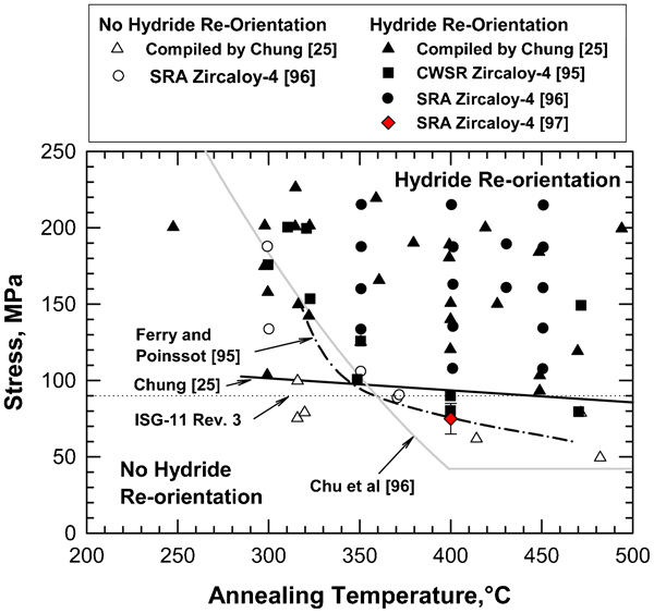
Critical tensile stresses for hydride reorientation as a function of temperature compared against experimental data compiled by Chung,25 cold worked and stress relieved (CWSR) Zircaloy-4 data compiled by Ferry and Poinssot,95 and stress relief annealed (SRA) Zircaloy-4 by Chu et al. 96 and Daum et al. 97 The stress limit defined in the NRC Interim Staff Guidance-II Revision 3 (ISG-II Rev. 3)94 is shown as the dotted line
Potential repository environment
For fuel rods in a potential waste repository environment, the cladding stress was computed to be in the range of 60–100 MPa (8·7–14·5 ksi), based on consideration of the internal rod pressure due to fission gas release and a uniform cladding diameter.48,98 This estimate of the cladding stress is likely a lower bound because non-uniform cladding diameter changes induced by PCMI and stress concentration at the ridges was not taken into account in the previous stress calculation.
Computing the local hoop stress at the ridges in cladding tubes in a potential repository requires knowledge of (1) the anticipated temperature gradient between the pellet fragments and cladding, (2) swelling or the presence of voids in the fuels61 and (3) bonding or welding between the fuel fragments and cladding wall.36,61 The latter two phenomena could prevent the fuel pellets from separating from the cladding, thereby allowing a high local stress to be maintained at the ridges after a power ramp.59 One possible estimate of the upper bound hoop stress in cladding tubes after service may be the relaxed stable hoop stress in the cladding after an in-reactor power ramp, because the temperature gradient, the extent of fuel expansion, and the contact between fuel and cladding are at the maximum levels. The relaxed PCMI stress values range from 200–400 MPa (29–58 ksi) based on the computational results of Brochard et al.,53,54 Suzuki and Uetsuka58 and Schäffler et al. 57 The actual unrelaxed PCMI stresses may be less than 200–400 MPa (29–58 ksi), depending on the stress relaxation processes and the bonding between pellet and cladding. Over a period of 104–106 years, cladding tubes in a potential repository might encounter one or more seismic events and impact loading from rockfalls that can cause transient loading on the cladding in successive bursts. The transient cladding stress during a seismic event or a rockfall is expected to lead to a high stress intensity factor at an existing crack in the cladding in a very short time. The general characteristics of the K profiles for these transient stress fields would be similar, but with different amplitudes, durations and stress relaxation times. For impact loading, subsequent DHC growth may be feasible under the stress transient results in a fracture of the surface oxide layer, hydride blister or rim, or radial hydrides to create or extend a crack so that K>K IH. Under this circumstance, DHC may occur after a rock fall event; the DHC growth kinetics would then be dictated by the duration of the transient stress, the crack lengths, the cladding temperature, the cooling rate and the properties of the degraded cladding.
DHC in fuel rod cladding during in-reactor power ramps
Internal gas pressure
The propensity to DHC in fuel rod cladding tubes due to internal pressure and local transient stresses induced by PCMI is considered in this section. In particular, the plot of critical stress versus crack length shown in Fig. 7 for Zr–2·5Nb has been extended to zircaloy fuel cladding because comparable experimental data for Zircaloy-2 or Zircaloy-4 are incomplete and are insufficient for statistical analysis. As shown in Fig. 6, experimental results on Zircaloy-2 tubing by Huang and Mills38 indicated that the K IH value for Zircaloy-2 tubing ranged from 5·2 to 8·4 MPa m1/2 (4·7–7·6ksi in.1/2), compared to 5·5–9 MPa m1/2 (5–8·2 ksi in.1/2) for Zr–2·5Nb materials with closely matched crystallographic textures. The activation energy for DHC in Zircaloy-2 was determined to be 65·3 kJ mol−1 (15·60kcal mol−1),38 which is essentially identical to the experimental value of 65·5 kJ mol−1 (15·65 kcal mol−1) for Zr–2·5Nb.12 Mills and Huang38 indicated that the DHC growth rates in Zircaloy-2 tubes were comparable to those observed in Zr–2·5Nb tubes with similar crystallographic textures. Because the DHC properties are similar, extending Fig. 7 for Zr–2·5Nb to Zircaloy-2, therefore, requires only the assumption that the fracture strengths for hydrides in Zr–2·5Nb are comparable to those for fracture of hydrides in Zircaloy-2. On this basis, the calculated curves based on large crack K IH thresholds of 5·36 and 12 MPa m1/2 (4·9 and 10·9 ksi in.1/2) are applicable to both Zircaloy-2 and Zr–2·5Nb, because the actual experimental data of these two alloys lie within these two limits. There is a general consensus that the cladding stress level due to internal fission gas pressure [60–100 MPa (8·7–14·5 ksi)] results in a stress intensity level that is on the order of 0·5–2 MPa m1/2 (0·46–1·82 ksi in.1/2), which is lower than the K IH of 5 MPa m1/2 (4·6 ksi in.1/2) required for the onset of DHC growth. Hence, DHC by internal gas pressure alone is considered unlikely, as indicated earlier, when the initial crack sizes are estimated on the basis of the size of manufacturing defects in the cladding. Figure 23 compares the cladding stresses against the critical stresses for the onset of DHC for semicircular cracks with large crack thresholds of 5·38 MPa m−1 (4·9 ksi in.1/2) and 12 MPa m−1 (10·9 ksi in.1/2) and the corresponding small crack threshold stresses. The nominal stresses in the cladding due to the internal gas pressure are well below the critical threshold stresses required to cause DHC in either Zr–2·5Nb or Zircaloy-2.
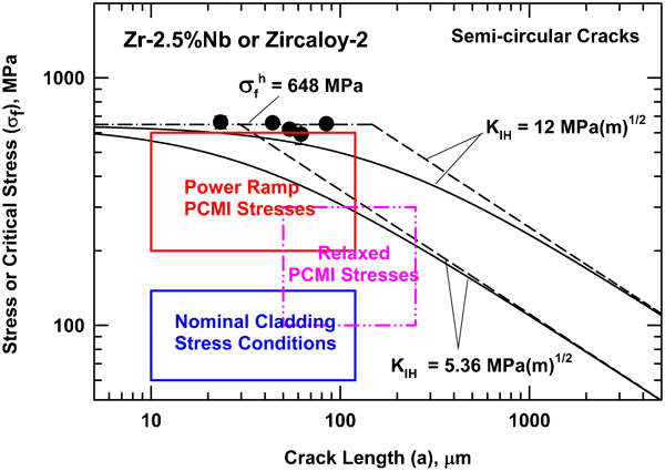
A comparison of cladding stresses under various loading conditions and crack lengths against the large crack and small crack threshold stresses for the onset of DHC in Zr alloy cladding tubes made of Zircaloy-2 or pressure tubes made of Zr–2·5Nb (1 MPa = 0·145 ksi; 1 MPa m1/2 = 0·91 ksi in.1/2; 1 μm = 0·0394 mil)
Transient stress
The transient stress during power ramps can be high and sufficient to cause DHC. The transient PCMI stresses during power ramp are compared with the threshold stress in Figure 23. The comparison indicates that the PCMI transient stress exceeds the threshold stress for DHC for crack depths greater than 80–120 μm (3·2–4·7 mil). Applying the transient hoop stresses computed by Brochard et al.,53,54 Suzuki and Uetsuka58 and Schäffler et al.
57 to DHC indicated that the extent of DHC growth critically depends on the time duration at which the local stress intensity exceeds the K
IH. The DHC growth calculations were performed using a semicircular crack assumption. The cladding tube was assumed to contain a 100 μm (3·9 mil) thick oxide layer with a 150 μm (5·9 mil) hydride blister layer formed beneath the oxide layer. The initial crack depth was taken to be half of the oxide thickness. The oxide layer failed when K>

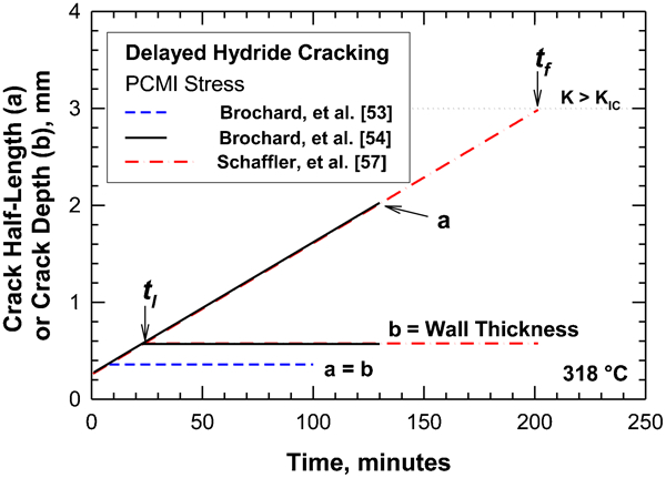
DHC growth resulting from PCMI stress transients during power ramps. Crack extension was computed for Zr–2·5Nb cladding on the basis of PCMI stress transients reported by Schäffler et al. 7 and Brochard et al. 53,54 (1 mm = 39·4 mil; 318°C = 604·4°F). Leakage occurs at t l where the crack depth (b) ≧cladding wall thickness. Cladding fracture occurs at t f where K≧K IC
In an overview paper, Chung25 summarised several instances involving failure of high burnup cladding. Under various usage conditions, high burnup cladding is subjected to PCMI stresses not only at high temperatures [380–420°C (716–788°F)], but also during subsequent slow cooling to a lower temperature [e.g. 200°C (392°F)]. The transient local stresses can induce the precipitation of radial hydrides in significant amounts in some local regions, sometimes leading to cleavage fracture and RHA-DHC. Inner wall cracks were found in a high burnup Zircaloy-4 PWR fuel during pre-test heating of a simulated RIA-like pulse test. The length of the inner wall cracks ranged from 20–480 μm (0·79–18·9 mil), and many were partially covered with hydrides.25 Based on the metallographic and fractographic characteristics of the inner wall cracks, Chung25 suspected that these cracks might have been caused by RHA-DHC. This is because numerous local regions were found to contain radial hydrides that were in tight contact with the pellet–cladding bonding layer where high transient tensile stresses could be induced by PCMI. Brittle cracks consistent with RHA-DHC were reported at the outer and inner walls of Zircaloy-2 BWR fuel cladding tested under a power ramp with a hold time for tubes with and without a primary defect.20,22,36 In non-lined BWR failed rods with Zircaloy-2 cladding, Lin et al. 20 observed a long [287 μm (11·3 mil)] outside wall crack with radial hydrides at the crack tip. In addition, radial hydrides were observed to emanate from the outer and the inner cladding walls. The lengths of the radial hydrides that emanated from an outer wall were on the order of 300–390 μm (11·8–15·3 mil), compared to 90–240 μm (3·5–9·4 mil) from an inner wall. Cheng et al. 21 reported hydride cracks of various lengths [50–200 μm (2–7·9 mil)] initiated from the outer and inner walls in both Zr lined and non-lined Zircaloy-2 cladding tubes. Localised oxide layer on the order of 70–150 μm (2·8–5·9 mil) in thickness was observed.22 A hydride rim over 80 μm (3·1 mil) thick was observed on the outer surface. Radial hydrides that emanated from the hydride rim ranged from 160 to 340 μm (6·3–13·4 mil) in length. Non-lined Zircaloy-2 was also prone to the formation sunburst hydrides below the hydride rim. Hayashi et al. 36 also reported that brittle cracks initiated from radial hydrides formed at the outer walls of Zircaloy-2 cladding tubes of high burnup fuel rods. The crack size ranged from 40 to 330 μm (1·6–13 mil) in the through-thickness direction. Some of the observed cracks propagated entirely through the wall thickness and became axial cracks. The length of the axial cracks was 700 μm and higher. Hayashi et al. 36 identified RHA-DHC as the cladding failure mechanism by showing the presence of radial hydrides at the crack tip. They also reported that the oxide thickness ranged from 30 to 100 μm (1·2–3·9 mil) and the length of the radial hydrides was about 70 μm (2·8 mil).36
The transient nature of the PCMI stresses dictates that DHC growth during power ramp does not lead to immediate cladding failure or the development of a leak in the cladding. Instead, the damage process appears to involve the accumulation of small increments of DHC growth over a long time or after numerous power ramping events. The power ramp transient stresses produce two effects that can affect the integrity of cladding tubes under subsequent repository conditions: (1) the generation of local residual stresses at ridges in cladding under normal operating conditions in reactors and repositories and (2) a distribution of defect or crack sizes that evolve with time and are considerably larger than the initial manufacturing defect sizes. Both the local stress and the crack size distribution can significantly affect the propensity to DHC growth in cladding tubes in a repository environment, illustrated by the box in Fig. 23. The relaxed PCMI stresses computed by Brochard et al. 53,54 and Suzuki and Uetsuka58 are about 100–300 MPa (14·5–43·5 ksi), and the corresponding crack depths are 50–250 μm (1·97–9·84 mil). The larger crack depth is based on a 120 μm (4·72 mil) oxide crack and a 130 μm (5·12 mil) hydride crack formed beneath the oxide layer by DHC or fracture of a hydride blister during power ramps. These oxide thicknesses and hydride blister sizes have been estimated on the basis of the experimental observations by Cheng et al. 21 on Zircaloy-2 that showed the localised oxide layer thickness was about 70–150 μm (2·8–5·9 mil). A hydride rim over 80 μm (3·1 mil) thick formed on the outside surface with radial hydrides 160–340 μm (6·3–13·4 mil) in length that emanated from the hydride rim.22 For a crack depth of 250 μm (9·8 mil), the relaxed PCMI stresses are comparable to those required to start DHC. In contrast, DHC does not occur at stresses below 200 MPa for K IH = 5·36 MPa m1/2 (4·88 ksi in.1/2). For zirconium alloys with low oxide thickness and hydrogen pickup (e.g. M5), the initial crack depth may be substantially less than 250 μm (9·8 mil); DHC would not be feasible at a cladding stress of 200 MPa (29 ksi).
Type I transient stress during a cool-down
Without the local stresses at the ridges, the cladding hoop stresses from the internal gas pressure alone may not be sufficiently high to cause DHC in cladding tubes under dry storage and repository conditions. To produce substantial DHC, the local stress intensity factor at cladding must exceed K
IH for a sufficient time period without being relaxed below this critical value. Of the two transient stress types, the one modelled by Schäffler et al.
57 and another described for reactor ramp-up by Suzuki and Uetsuka58 are capable of producing substantial DHC growth because of an extended duration where K>K
IH. For cladding tubes under potential repository conditions, the amount of crack extension generated by this type of local stress distribution also depends on the cladding temperature and cooling rate. For DHC under a cool-down from a given temperature [e.g. 320°C (608°F)], the crack extension per unit temperature change dT can be derived from equation (11) and is given by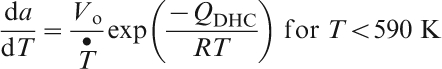
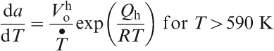


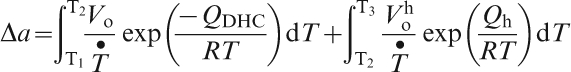
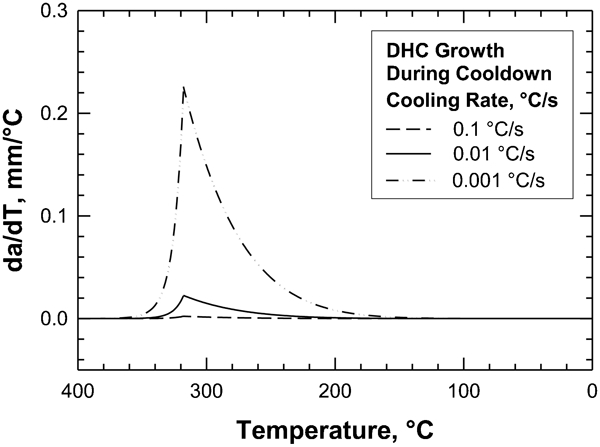
DHC growth rate per unit temperature change as a function of cladding temperature for three cooling rates [1 mm °C−1 = 0·022 in. °F−1; T (°F) = 1·8T (°C)+32; 1°C s−1 = 1·8°F s−1]
DHC crack extensions and time of growth as function of cooling rates
Table 3 shows that the amount of DHC extension is about 0·1 mm (3·94 mil) for a cooling rate of 0·1°C s−1 (0·18°F s−1, and the time spent in DHC growth is 1·1 h. When the cooling rate is reduced to 0·01°C s−1 (0·018°F s−1), the time for DHC growth increases to 11·11 h, and the amount of DHC extension increases to 1·07 mm (42·1 mil). Further decrease in the cooling rate to 0·001°C s−1 (0·0018°F s−1) increases the DHC time to 111 h and the amount of DHC extension to 10·7 mm (0·42 in.).
Type II transient stress
For Type II transient stress, the peak stress intensity factor exceeds the K
IH value and results in DHC growth for a short time period during a power ramp. After the power ramp is completed, the equilibrium stress is stabilised at a stress intensity factor K that drops below the K
IH and terminates DHC growth. Under this circumstance, DHC remains dormant until either the local stress is increased or the K
IH value is equivalently reduced so that K>K
IH. When K>K
IH, DHC resumes and the crack growth process can be analysed using the procedure described for treating Type I transient stress. When K<K
IH, DHC ceases and the crack length remains constant until another transient stress cycle causes the K value to exceed K
IH again. This is shown in Fig. 24, which presents the results of computations based on the Type I PCMI stress transients reported by Brochard et al.
53 Consequently, the cumulative DHC extension depends on the number of transient stress cycles, the time period within which K>K
IH, the cladding temperature, and the cooling rate. The time t
h required for the diffusion of hydrogen to form hydrides at a crack tip can be estimated from the expression
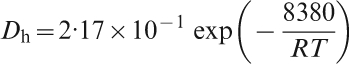
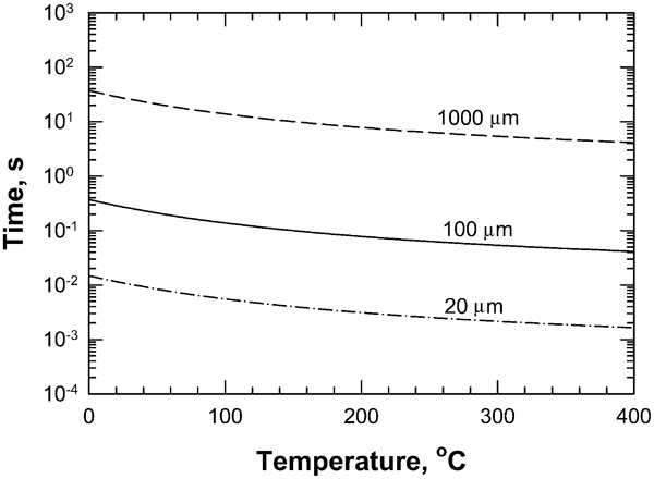
Times required for the diffusion of hydrogen atoms from various distances to form hydrides at the crack tip [T (°F) = 1·8T (°C)+32; 1 μm = 0·0394 mil]
The high transient stresses associated with power ramps can potentially cause hydride reorientation (Fig. 22), and leading to crack initiation in cladding by fracturing a hydride blister and a number of radial hydrides. Once a crack of sufficient depth is formed, the stress due to the internal gas pressure might then be large enough to cause subsequent DHC growth. If not, DHC growth would cease and remain dormant until the crack is reactivated by a subsequent transient stress cycle. At 318·5°C (605·3°F), the time to leakage and future DHC are 24 and 198 min respectively. They are in accordance with the experimental observation (9–149 min) reported as power ramp test of segmental rods.36
Discussion
DHC in zirconium alloy cladding tubes
Extensive review of literature data2,10,11 and FEM computations53 – 59 indicate that DHC in zirconium alloy cladding requires local transient stresses induced by PCMI during power ramping. Without these transient PCMI stresses, the cladding stresses due to internal gas pressure alone are not sufficiently high to produce a stress intensity factor at a manufacturing defect or crack to exceed the growth threshold K IH for DHC. The relatively large PCMI stresses can cause hydride reorientation, leading to a variety of hydride microstructures that are prone to brittle crack formation, followed by DHC. The frequency of PCMI occurrence during power ramps is not known, and the corresponding hydride microstructures have not been fully characterised. Thus, characterisation of hydride morphology in the cladding tubes of high burnup fuel rods would indicate the frequency of the PCMI occurrence.
At least two types of transient stress profiles have been identified. Type I transient leads to continuous DHC growth until cladding failure, while Type II transient results in intermittent DHC growth and arrest. High burnup fuel rods, which may experience numerous power ramps, are likely to contain cracks that have been initiated by oxide cracking, blister fracture or corrosion and subsequently extended by DHC. A range of crack depths generated by DHC may be expected because the driving stresses are transient and vary with thermal and mechanical loading histories, hold times and the number of power ramps. Currently, very little information is available about the hydride size distribution and the crack depth distribution in cladding tubes after they are removed from service. Without an accurate assessment of crack depth and hydride blister size, there are great uncertainties on the cladding stress required to cause K>K IH, the cladding resistance against DHC growth during the operation period before disposal.
The peak cladding temperature history for the centre rod in the waste package during the operation period before disposal is about 325°C (617°F).49 Because of the high DHC propagation rate near 318°C (604°F), the time to leakage is on the order of a few hours if K>K IH in any cladding tubes. DHC may occur based on internal gas pressure alone if large hydride blisters or radial hydrides are present in the microstructure, the fracturing of which leads to K>K IH. There is also a concern that slow cooling rates (10−6–10−7°C s−1) may reduce the K IH value by forming a long continuous hydride at the crack tip. Experimental K IH data needed to address this issue currently do not exist.
Effects of temperature on DHC
The cladding temperature has a significant effect on DHC growth in zirconium cladding tubes. The worst DHC growth resistance in Zr–2·5Nb occurs at around 310–320°C (590–608°F), with an estimated time to leakage of 24 min and an estimated time to failure of about 3·3 h. For both cladding leakage or fracture, the time to failure increases with increasing temperature above 310–320°C (590–608°F) because of slower hydride formation kinetics, while the time to failure increases with decreasing temperatures below 310–320°C (590–608°F) because of slower hydrogen diffusion. As a result, power ramping at around 310–320°C (590–608°F) can cause cladding failure by DHC in as little as 24 min for leakage or 3·3 h for cladding fracture. Power ramping above 350°C (662°F) would prevent DHC initially, but results in DHC when the cladding temperature cools slowly from 350°C (662°F) to lower temperatures, while the transient stresses are still high. The time to leakage is about one-eighth of the time to fracture at a given temperature. The lower DHC growth resistance at 310–320°C (590–608°F) occurs as a result of a high crack growth rate, despite a higher fracture toughness compared to that at lower temperatures. At ambient temperature, the DHC growth is exceedingly slow, making the time to propagate a DHC through a cladding wall thickness of 0·56 mm (22·1 mil) about 10 years. Thus, a low cladding temperature can effectively suppress DHC in cladding tubes, regardless of the local stresses at the ridges.
Effect of burnup
The burnup level of fuel rods is one of the most important factors affecting the cladding performance and integrity. A high burnup can be detrimental to cladding integrity because the number of power ramps increases with increasing burnup, while the gap between pellet and cladding decreases. In high burnup fuel, the cladding tubes are likely to have experienced a greater number of transient stress cycles where high PCMI stresses can cause hydride reorientation, producing a variety of hydride microstructure and DHC growth compared to low burnup fuels. High burnup cladding tubes are also likely to contain thicker oxide or corrosion layers that can fracture during power ramping and serve as stress risers to initiate DHC at multiple sites. Power ramp tests conducted on segmented fuel rods36 revealed a change of cladding failure from one of pinhole perforation at low burnup (<45 GWd MTU−1) to one of RHA-DHC at high burnup levels (53 and 63 GWd MTU−1).
Effect of cooling rate
The propensity of DHC decreases with increasing cooling rates. Because DHC growth rates are higher at temperatures between 200 and 350°C (392–662°F), a high cooling rate means that less time is spent in this temperature range where the DHC propagates at high rates and consequently forms smaller crack extensions. A cooling rate exceeding 0·1°C s−1 (0·18°F s−1) gives a crack extension of <0·01 mm (0·39 mil), because the time spent in the high DHC growth regime is only about 1 h. The amount of DHC growth and time spent in the high DHC growth regime increase proportionately with decreasing cooling rates, as shown in Table 3. The slow cooling rates likely in a potential repository environment make the zirconium alloy cladding tubes susceptible to DHC growth, because there could be a significant amount of time spent at an elevated temperature where DHC growth kinetics are high.
Conclusions
PCMI (the section ‘Pellet–cladding mechanical interaction’) during in-reactor power ramping can cause stress transients at local ridges in cladding. The magnitude and duration of stress transients that can cause hydride reorientation and DHC growth in cladding tubes can be classified into two types: Type I stress transients that result in K>K IH over a long time duration and cause DHC failure and Type II stress transients that result in K>K IH and DHC growth for only a short time duration and arrest DHC growth when K drops below K IH.
High burnup cladding tubes are likely to contain crack sizes that are larger than those caused by manufacturing defects because of issues such as failure processes and the possibility of DHC during power ramps (the section on ‘DHC in fuel rod cladding during in-reactor power ramps’). The crack sizes in cladding tubes are uncertain because the PCMI transient stresses during in-reactor power ramps and the corresponding DHC extensions are generally not well defined.
The growth threshold K IH for DHC in zirconium alloys (Zr–2·5Nb and Zircaloy-2) has a value of about 5 MPa m1/2 (4·55 ksi in.1/2) or higher at ambient temperature (the section on ‘Threshold stress intensity factor K IH’). A higher K IH value can result from toughening due to the compressive stresses accompanied by hydride formation at the crack tip and crack bridging by intact ductile zirconium grains in the crack wake (the section on ‘Threshold stress intensity factor K IH’). A K IH lower than 5 MPa m1/2 (4·55 ksi in.1/2) is also theoretically feasible when long hydrides form at the crack tip under very slow cooling rates, but this theoretical prediction has not been verified by experimental data. Although K IH is better described in terms of a probability distribution whose parameters vary with cooling rate, texture, temperature and neutron fluence, a constant value of K IH = 5 MPa m1/2 (4·55 ksi in.1/2) can be used as a conservative criterion for the onset of DHC with a 95% confidence limit (the section on ‘Transient stress’).
The amount of DHC growth in zirconium alloy cladding tubes depends on the thermal mechanical history experienced (the section on ‘Transient stress’). Theoretical analysis indicates that cooling rate significantly affects DHC growth because it determines the times that hydride cracks spend at elevated temperatures where the growth rates are high. With decreasing cooling rates, the time to failure decreases, but the amount of DHC growth increases. The very slow cooling rates anticipated in a potential repository make cladding tubes susceptible to DHC unless the cladding temperature and the stress are kept low.
The growth threshold K IH for DHC may be insensitive to the crack length because of a small crack limit that is about 20 μm (0·79 mil) or less (the section on ‘Threshold stress intensity factor K IH’). Because the critical length for hydride fracture could be on the order of 10 μm (0·39 mil), a hydride crack behaves as a long crack almost as soon as it is initiated. Thus, it is not necessary to consider the effects of crack size on the K IH value beyond that of a large crack in zirconium alloys when the applied stresses are less than 300 MPa (43·5 ksi) (the section on ‘Temperature dependence of DHC’).
Theoretically, DHC growth kinetics of zirconium alloys are the highest at the 300–320°C (572–608°F) temperature range. A theoretical analysis indicates that the DHC growth rate decreases with increasing temperatures above 320°C (608°F) and is suppressed at temperatures above 350°C (662°F) due to high hydrogen solubilities (i.e. the possible absence of hydride formation at the crack tip). Furthermore, the crack growth rate decreases with decreasing temperatures below 300°C (572°F) because of slower hydrogen diffusion kinetics to the crack tip. Thus, according to the theoretical analysis, zirconium alloy cladding is most susceptible to DHC at temperatures ranging from 300 to 320°C (572–608°F). Sustained loads at these temperatures should be avoided to minimise DHC.
The time to leakage is about one-eighth of the time to fracture for zircaloy alloy tubes (Zr–2·5Nb and Zircaloy-2) at a given temperature between 0 and 350°C (32–662°F) (the section on ‘Temperature dependence of DHC’). The time to leakage is computed based on a crack depth reaching the cladding-computed wall thickness of 0·57 mm (22·4 mil), and the time to fracture is computed based on a critical stress intensity factor of 70 MPa m1/2 (63·7 ksi in.1/2).
Footnotes
Acknowledgements
The author wishes to thank G. Cragnolino for his technical review and B. Sagar for his programmatic review. Thanks are also expressed to L. Mulverhill for her editorial review and L. Naukam in preparing the document.
This paper was prepared to describe work performed by the Center for Nuclear Waste Regulatory Analyses (CNWRA) for the US Nuclear Regulatory Commission (NRC) under Contract No. NRC-02-07-006. The activities reported here were performed on behalf of the NRC Office of Nuclear Material Safety and Safeguards, Division of High-Level Waste Repository Safety. This paper is an independent product of CNWRA and does not necessarily reflect the view or regulatory position of NRC.