
Abstract
A comprehensive and integrated review of thermal barrier coatings (TBCs) applied to turbine components is provided. Materials systems, processes, applications, durability issues, technical approaches and progress for improved TBC, and our understanding of the science and technology are discussed. Thermal barrier coating prime reliance and further advances have been hampered by TBC loss by particle impact and erosion in certain locations of the turbine blades. Accumulation of low melting eutectic containing calcia, magnesia, alumina and silica resulting in TBC spallation limits maximum surface temperature. Design methodologies to address durability and data scatter issues are discussed. Compositions, morphology, characteristics and performance data for new bonds to achieve longer TBC life are described. Further reduction in the thermal conductivity of the top layer to minimise the parasitic mass of the coating on the component is being sought via top layer composition and processing modifications as well as by alternate ceramic compositions. The progress in these areas is critically reviewed including processing, stability and durability limitations. The paper also describes effort to understand various failure mechanisms including modelling and simulation.
Introduction
Application of thermal barrier coatings (TBCs) on cooled turbine engine components such as combustors, high pressure turbine (HPT) blades and HPT nozzles is increasing in commercial and military jet engines. This trend will certainly continue because the insulating capability of TBC enables higher operating temperatures and/or permits a reduction in the required amount of cooling air, thereby improving efficiency, reducing emission and increasing thrust/weight ratio. Power generation turbine engines are also increasingly using TBC. Thermal barrier coatings are also slated to be used on components made out of ceramic–matrix composites (CMCs).
A schematic of a TBC system on an HPT blade is shown in Fig. 1. Thermal barrier coatings are currently used to provide metal temperature reductions of up to ∼100°C (Fig. 1b ), while potential benefits are estimated to be greater than ∼200°C. Factors that determine temperature reductions include part geometry and location, heat flux, heat transfer coefficients, backside cooling air, TBC thickness and thermal conductivity. The temperature benefits are highly significant and surpass other material technologies advances including single crystal Ni based superalloys (Fig. 2) achieved over a 30 year period. The initial applications were driven by the need to suppress component degradation due to excessive surface temperatures in combustors and some selected turbine aerofoils experiencing oxidation damage. In spite of significant improvements, TBCs are yet considered ‘prime reliant’ because of local spalls and reduction in thickness, and full utilisation has eluded turbine designers. Research and technology developments have been carried out for the last two decades to address performance and reliability while extensive research is being carried out for higher temperature applications beyond the baseline system, and for TBC with lower thermal conductivity.
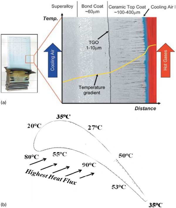
a An HPT blade coated with TBC. TBC components (bond coat and top coat) are shown with temperature drop though the thickness of TBC. b An example of temperature drop in an HPT by TBC application
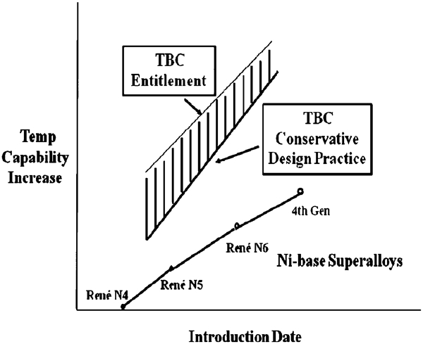
Turbine temperature advancement with TBC compared with Ni based superalloys
Thermal barrier coatings are complex, multilayered and multimaterial systems with many variants related to composition, processing and microstructure. There are over 400 publications on this subject. This review paper will describe the currently used TBC materials systems and summarise our current understanding of the science, technology and failure mechanisms. Emphasis will be placed on engineering application aspects to draw on the author’s vast experience directing TBC research at a major aerospace company in collaboration with many universities and national laboratories. References selected based on relevance and scientific value are provided. Recent review papers1 – 10 capture various aspects of the TBC technology and provide excellent additional background. The author has also relied heavily for insight for his research on papers in five conference proceedings ‘Science and technology of zirconia, Volumes I–V’11 – 13 that are excellent sources for fundamental information on sintered or hot pressed ‘bulk’ zirconia based materials. The author has found that the properties and behaviour in the coating form are quite similar to those of the bulk materials.
Thermal barrier coating application
Thermal barrier coatings are applied to components which are internally cooled by directing air though channels. Designs with TBC coated parts consider part configuration and thickness, heat flux, heat transfer coefficients, combustion and turbine inlet temperatures and total cooling air allowed by the system engineers. To minimise adding excessive mass and cooling hole closure, thinner coatings are preferred.
Main components in propulsion turbine engines where TBC is applied are shown in Fig. 3. The combustor liners were the first components to routinely use TBC applied by an air plasma spray (APS) process. Thermal barrier coatings on aeroturbine blades are applied by an electron beam physical vapour deposition (EB-PVD) process. The larger components of the power generation turbines (combustor, several stages of nozzles and blades, referred to as buckets) predominantly use the APS process because of their larger size. Thermal barrier coating thickness on aerorotating parts is typically 100–250 μm compared to 250–500 μm on the stationary components such as shrouds, nozzles and combustor parts. In these parts, both EB-PVD and APS processes are considered. The rationale for the process choices will be described in the section on ‘Processing methods for top coat’. Component designs with TBC have evolved from simply applying a thin layer of TBC on existing components to sophisticated design practices based on laboratory test data and observations from the field returned hardware. It is also planned to use TBC on components made out of CMCs.
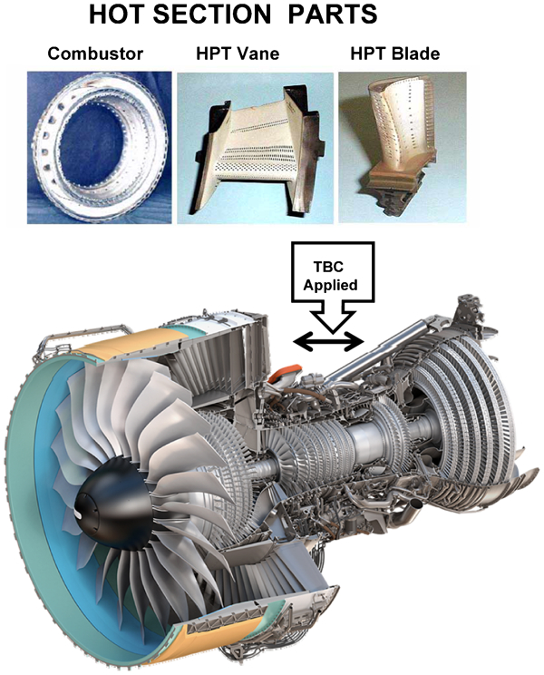
Examples of TBC application in propulsion engines. Combustor liners, HPT blades and vanes are coated with TBC
Constituents of TBC system
Thermal barrier coatings are primarily a two layer system consisting of a porous (porosities generally in the range of 10–25%) ceramic top coat layer comprising zirconia (ZrO2) ‘partially stabilised’ with about 6–8 wt-% (∼3·4 to 4·5 mol.-%) yttria (Y2O3) generally referred to as 7YSZ or YSZ, and an alumina forming bond coat layer, primarily of NiCoCrAlY or NiAlPt based compositions. Expanded views of an EB-PVD TBC microstructure can be seen in Fig. 4a and b . There are four main components with unique functions that influence TBC life as shown in Fig. 5:
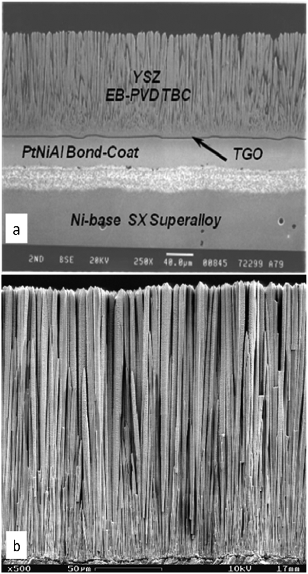
a TBC microstructure with four components (Ni based superalloy, bond coat, TGO and YSZ top coat). Note the columnar microstructure of the zirconia coating. The white band is an interdiffusion layer between the Al rich bond coat above and the Ni rich superalloy. b Expanded view of zirconia top coat
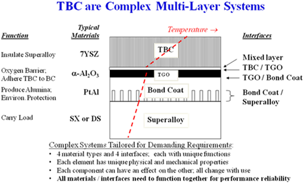
Thermal barrier coating consists of four main components with unique functions that influence TBC life
top coat layer: provides thermal insulation
thermally grown oxide (TGO) layer: provides bonding of TBC to bond coat and slows subsequent oxidation
bond coat layer: contains the source of elements to create TGO in oxidising environment and provides oxidation protection
superalloy substrate: carries mechanical load.
Each of these components has markedly different physical, thermal and mechanical properties that are strongly affected by processing conditions. During fabrication and most notably during use, these components interact chemically and mechanically. Dynamic relationships between these layers control the durability of TBC. It must be pointed out that the composition and the microstructures of these layers are continually changing during service. Properties measured in the as fabricated condition could lead to misleading conclusions. Interfaces between the layers also play a significant role. An additional layer, about 0·05–0·1 μm thick, referred to as ‘mixed zone’ (Fig. 6),14 forms between the TGO and YSZ lop layer during preheating and top layer deposition by the EB-PVD process. This layer consists of zirconia and yttria particles dispersed in the TGO matrix.14 It is likely that this layer influences TGO/TBC adhesion, though further studies are warranted.
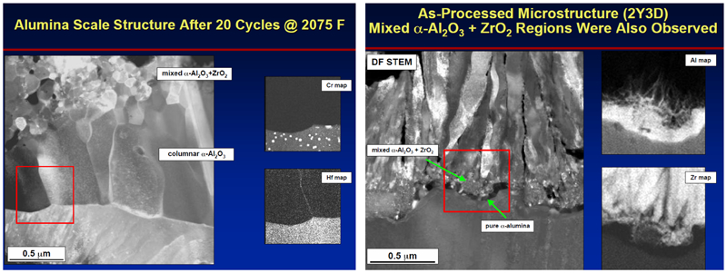
a TGO microstructure, predominantly α-Al2O3 and b mixed zone of α-Al2O3+ZrO2
Yttria stabilised zirconia top coat
Yttria stabilised zirconia has high melting point (not of much significance to current usage), low thermal conductivity, high oxygen permeability and relatively high coefficient of thermal expansion compared to other oxides and the 6–8 wt-%Y2O3 composition is relatively stable during high temperature exposure. An important attribute of YSZ for turbine design is that thermal conductivity is essentially temperature invariant. Another important attribute of YSZ is that ZrO2 and Y2O3 have similar vapour pressures allowing deposition of YSZ with uniform composition by the EB-PVD process. This is unlike alternate TBC materials containing oxides of different vapour pressures yielding undesirable, non-uniform and layered structures. Yttria stabilised zirconia is applied either by APS or EB-PVD techniques. These processes make YSZ ‘strain tolerant’ by depositing a structure that contains numerous pores, gaps, microcracks and interfaces (Fig. 7). Strain tolerant structures are necessary to accommodate thermal expansion misfit between the substrate and top layer. The high oxygen permeability of the YSZ requires that the bond coats be highly resistant to oxidation and hot corrosion attack. The bond coat compositions are rich in aluminium to form a protective, TGO scale of α-Al2O3, typically 1–6 μm. The NiCoCrAl (Y, Hf, Si and Re) type overlay bond coats, typically 100–200 μm, are mainly based on the γ-Ni and β-NiAl phases. The Pt platinum modified diffusion aluminide bond coats, typically 50 μm, mainly consist of a β-NiAl–Pt phase. In addition to enhancing oxidation resistance, TGO serves to bond the ceramic top coat to the substrate/bond coat system. Thickening and buckling of the TGO scale and subsequent cracking is one of the several failure mechanisms of TBC. The adhesion and mechanical integrity of the TGO scale is dependent on the composition and impurity levels of the bond coat.
Types of TBC porosity
A pseudobinary ZrO2–Y2O3 phase diagram modified by Levi1 is shown in Fig. 8. In this figure, the Y2O3 content in the x axis is labelled as mole fraction YO1·5 since wt-%Y2O3 roughly translates to 0·5 mol.-%Y2O3 in ZrO2–Y2O3 compositions. Numerous modifications to precisely define phase boundaries have been proposed.15 As opposed to the equilibrium tetragonal phase t (t-ZrO2), a closely related non-equilibrium, metastable phase t (t'-ZrO2) is obtained in the as deposited TBC due to high rate deposition by either APS or EB-PVD. This phenomenon is highly desirable for achieving optimised lives. Though thermodynamically driven to partition into equilibrium t+c, the t' phase does not transform easily to tetragonal and monoclinic phases under normal circumstances until at least ∼1200°C,16,17 which is adequate in current use. Stability will become an issue for higher temperature operations. Transformation to monoclinic phase at lower Y2O3 contents is undesirable due to significant volume change (∼3 to 4%) causing cracks and TBC spallation. Higher Y2O3 contents have been shown to have lower fracture toughness, a possible cause of lower erosion and impact resistance to be discussed later.
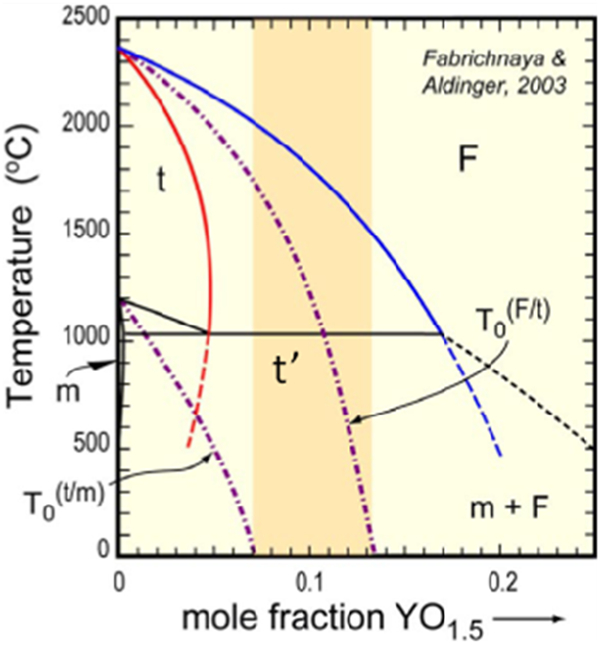
The zirconia rich corner of the ZrO2–YO1·5 binary phase diagram. Yttria stabilised zirconia composition and operating temperature range are shown by the hatched region. The tetragonal prime phase is metastable within the T o bounds shown as dashed lines superimposed on the phase diagram (courtesy: Professor Carlos Levi, UCSB)
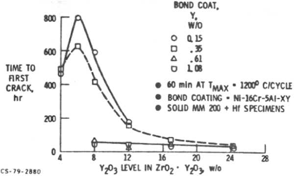
During the initial TBC development originating at NASA during the 1970s, it was demonstrated by Stecura18 – 20 in APS TBC that about 6–8 wt-% (∼3 to 4·5 mol.-%) Y2O3 addition to ZrO2 provided the longest TBC thermal cycle life in burner rig tests, even though ZrO2 was not fully stabilised. This conclusion was drawn with different test temperatures and various bond coat compositions. Time to first crack related to subsequent TBC spallation in thermal cycle tests as a function of Y2O3 content and four composition variations of NiCrAlY bond coat is shown in Fig. 9. Later, Stecura evaluated Yb2O3 containing ZrO2 and concluded that maximum life is obtained between 12·4 and 14·7 wt-%Yb2O3. Thermal barrier coating life decreased very rapidly at concentrations exceeding these optimum values. It must be pointed out that, after extensive research for the last two decades to identify better top coat compositions, 6–8 wt-%Y2O3 content in ZrO2 continues to be optimum. Alternate oxide stabilisers evaluated primarily to reduce thermal conductivity have shown TBC lives to be inferior to YSZ to be discussed in a later section. To date, YSZ continues to be a material system of choice. It is interesting to note that Engel et al. 21 observed on ‘single-crystal’ ZrO2 that maximum fracture toughness and fracture strength are obtained around 4–5 wt-%Y2O3 (Fig. 10).
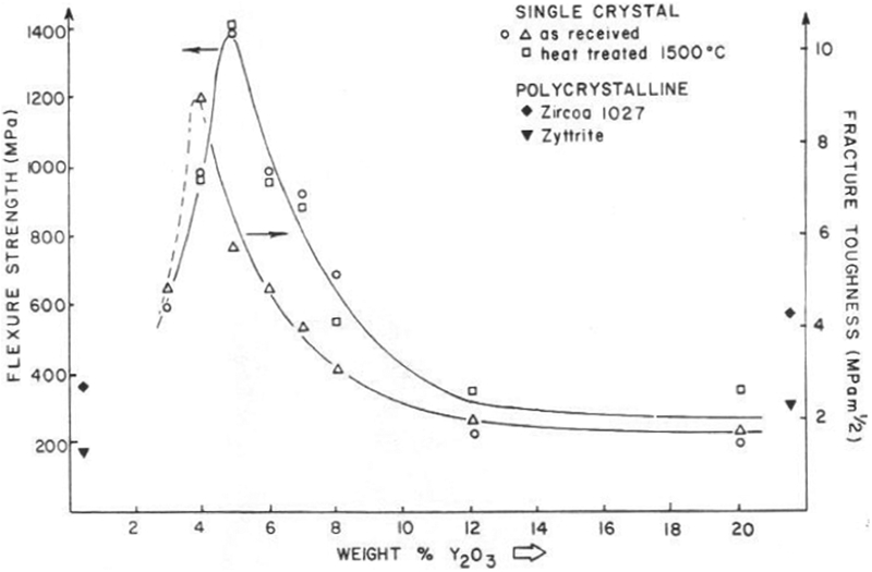
Flexure strength and fracture toughness of ZrO2 single crystals as a function of Y2O3 content (Engel et al.21)
It has been proposed by Virkar22,23 and Baither et al. 24 based on experiments on sintered ZrO2–3 mol.-%Y2O3 specimens that the t' phase microstructure consists of large grains on the order of 100 μm or greater. These grains contain very small domains (∼0·1 μm) arranged in three mutually orthogonal orientations in each grain making t' phase extremely non-transformable. However, these domains reorient under stress that provides high toughness, a phenomenon called ferroelastic domain switching. Mercer et al. 25 and co-workers have argued based on indentation and TEM studies that the nucleation of domains contributes to the toughness of YSZ TBC, and not the switching. This assertion was drawn by examining the material in the wake of an indentation induced crack by using TEM and by interferometry.
Yttria stabilised zirconia compositions are thermally stable up to the current use temperatures of TBC which is ∼1200°C. Yttria stabilised zirconia has shown minimum partition to the cubic+tetragonal phases which in turn transform to tetragonal+monoclinic phases respectively, upon cooling. It is another desirable attribute since destabilisation and subsequent monoclinic formation can lead to TBC spallation. Investigation on the thermal stability of YSZ and ZrO2 containing various stabilisers has been conducted more recently by Rebollo et al. 16 At higher temperatures, in addition to destabilisation, sintering can modify pore structure influencing thermal conductivity as well as strain tolerance.
Processing methods for top coat
Thermal barrier coatings are porous with overall porosities generally in the range of 10–25%. In the EB-PVD process, an ingot (or ingots) of a YSZ composition is vapourised in a vacuum chamber using a focused electron beam. Before deposition, the samples are preheated to ∼1000°C in a low oxygen partial pressure environment resulting in the growth of a thin (∼0·05 to 0·1 μm) TGO layer. The parts are coated by manipulation within the vapour cloud on the preheated substrate surface. The EB-PVD process is especially effective in tailoring microstructures and inplane modulus. For example, EB-PVD can yield a very desirable columnar microstructure (Figs. 7 and 11) to result in a low inplane modulus that provides strain accommodation for the coefficient of thermal expansion mismatch between the metallic substrate and the ceramic top coat. The air plasma spray process yields a microstructure with horizontal splats of YSZ (Fig. 11). The interfaces/gaps between the splats provide additional reduction in thermal conductivity and thermal expansion compliance with the substrate. The pore structure characteristics of EB-PVD and APS are schematically shown in Fig. 12 (reproduced from Ref. 26). Various versions of the plasma spray processes are used as an alternative to the expensive EB-PVD process. Excellent reviews of the APS process and processing parameters, and the control of coating characteristics and properties are provided by Sampath.26,27 During preheating and top coat deposition, and during subsequent heat treatments, the bond coat generates an adherent α-alumina layer (TGO) between the bond coat and the YSZ top coat. Formation of this α-alumina of optimal thickness and crystallography is critical to achieve reproducible TBC life and prevent premature spallation of the TBC. A TGO thickness of about 0·3–1·0 μm is considered optimum right after deposition.28 The TGO thickens during the TBC use, eventually contributing to TBC spallation. Thermal barrier coating failure mechanisms are discussed in the section on ‘Temperature and thermal cycle dependent failure’.
Thermal barrier coating top coat microstructures
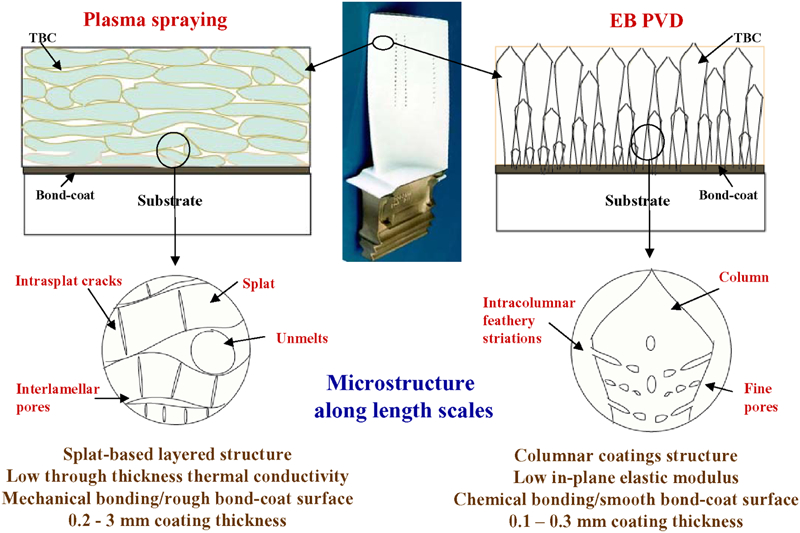
An illustrative description of microstructures of TBCs across length scales. The defect architectures of plasma sprayed coatings are differentiated from those of EB-PVD coatings26
Process selection considers performance, capital cost, per-part process cost, thickness requirements and control, composition requirements and control, surface roughness requirement, line of sight versus non-line of sight characteristics and degree of cooling hole closure. The EB-PVD process provides longer TBC life, smoother coating with excellent composition and thickness control, and causes minimum cooling hole closure. This process is preferred for blades and vanes in spite of much higher cost compared to the APS processes.
Air plasma spray processes are used for combustor parts, HPT shrouds and on most power generation components due to lower cost and requirement for thicker coatings. A variation of the APS process that is increasingly being used is ‘dense vertically cracked’ (DVC) TBC coating process.29 Vertical cracks are introduced to provide strain tolerance and serve similar function as intercolumnar gaps in the EB-PVD coatings at much lower cost. However, the performance is compromised in this lower cost version of the EB-PVD process.
Promising newer processing methods that are attempting to compete with EB-PVD and APS include directed vapour deposition, a variation of the EB-PVD process where a supersonic gas jet is used to direct vapours onto components being coated to increase process efficiency and deposition rate. The process acts as a non-line of sight process, and is able to coat multiple components with complex geometry.30 – 32 Composition uniformity and microstructural flexibility are other beneficial attributes. Suspension plasma spray or liquid solution precursor plasma spray33 – 35 creates microstructures with high segmented crack density and finer pores for reduced thermal conductivity and improved thermal cycle performance. The process employs suspensions of submicrometre particles as feedstock. This circumvents flow issues with finer particles in a powder feedstock, thereby, improving process efficiency. Microstructure and composition flexibility are two other advantages. A recent review of the developments in this technology is provided by Killinger et al. 36
Bond coat
Before introduction of TBC, turbine blades and vanes were protected from oxidative and corrosive environments with either diffusion coatings such as single phase, simple, β-NiAl or Pt modified β-NiAl or two phase overlay γ+β MCrAlX coatings (where M represents Ni or Co and X represents Y, Hf, Si, or other minor additives such as Re). The choice between these coating types by turbine engine manufacturers was based on experience, design philosophy, performance and cost. Although designed originally for environmental resistance, these coatings have been used as bond coats for TBC applications without any specific composition modifications and process development.
The MCrAlX type bond coats usually contain (in wt-%) 15–25%Cr, 10–15%Al and 0·2–0·5%Y, and consist of a β-NiAl phase in a γ-Ni matrix. These coatings, typically 100–150 μm thick, are applied using a variety of overlay processes: APS, high velocity oxyfuel, low pressure plasma spray, cathodic arc/ion plasma deposition or EB-PVD. The overlay coating processes are about 2–4 times more expensive than the diffusion processes, but offer much greater control of the coating composition since the coating composition is dictated essentially by the composition of the coating source. This attribute provides flexibility in depositing bond coat layers of various different chemical compositions. In actual practice, a knowledge of the vapour pressure, deposition efficiency and spatial distribution of all the chemical elements of the coating is required. The β-NiAl bond coats contain (in wt-%) 20–30%Al, and are generally applied by a diffusion process. Electroplating of Pt on the surface of the alloy precedes the diffusion cycle in the Pt modified β-NiAl bond coats. The diffusion processes enrich the component surface with Al. The composition of a diffusion coating is dictated by thermodynamic and kinetic constraints, and there are limitations on what multicomponent compositions can be deposited in reproducible and cost effective manner. The thickness is typically limited to about 40–60 μm. The β-NiAl coatings consist of an interdiffusion zone typically about the thickness of the top layer sandwiched between the alloy and the β-NiAl layer. A typical microstructure of TBC with a β-NiAl type bond coat and a TGO layer between the bond coat and the YSZ top layer is shown in Fig. 4a .
It must be strongly emphasised that environmental coatings form and reform the TGO layer as the coating is thermally cycled. In TBC applications, TGO spallation leads to TBC spallation. A significant level of understanding has been developed over the last two decades on various stages of TGO formation, growth and adhesion. The effects of major elements (aluminium, chromium and platinum) and minor elements additions (Y, Hf, Zr, Si, Pt and Re) have been studied extensively in bulk alloys and coatings. Of these, additions of small amounts of Hf, Y, Zr, Si and the elements (e.g. Ti, S, Hf and W) diffusing into the coating from the substrate play a critical role.6,37 – 59 A thin layer of Pt over a grit blasted NiCoCrAlHfSi coating surface has demonstrated a beneficial effect,44 though, this observation would have limited industrial application due to high cost of Pt. The effect of grit blasting,57 preoxidation58 and post-oxidation60 has been studied. Some of these modifications alter transformation kinetics of transient alumina such as θ-Al2O3 to α-Al2O3, faster establishment of α-Al2O3 being desirable.59 A remarkable effect on initial stages of oxide formation, transformation and growth kinetics has been demonstrated by Gleeson when Y, Hf and Si are added synergistically (codoping) at very low levels (Fig. 13).61 An excellent summary of research on the oxidation mechanism and bond coat compositions is provided by Gleeson.5 Impurities such as S and C in the starting materials and introduced during processing have a critical role on TGO scale adhesion, sometimes leading to infant mortality. The impurity effect will be discussed in section TBC scatter. A recent review on alumina scale formation is given by Heuer et al. 10
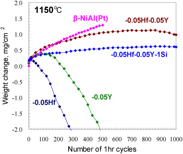
Synergistic beneficial effect of Hf, Si and Y in a β-NiAl coating composition61
Thermal barrier coating operating at higher temperatures will require improved bond coats capable of operating at higher temperatures. This is especially true if TBCs are used as a prime reliant coating. Localised TBC loss due to foreign object impact will probably be difficult to avoid. In this case, TBC loss will expose and rapidly oxidise the bond coat, causing rapid degradation of underlying substrate. However, it must be recognised that bond coat materials and the underlying substrate have similar thermal conductivities, and, therefore, improvement in bond coat temperature capability will be limited by the creep strength of the substrate. It should be pointed out that the extent of coating/substrate interdiffusion will increase as the operating temperature of the turbine increases. An ideal bond coat should have the following attributes:
oxidation resistance by forming a slow growing, non-porous, continuous and adherent α-Al2O3 scale layer (TGO)
minimal interdiffusion with the substrate to minimise Al depletion and upward diffusion of refractory elements and impurities such as S, and avoid formation of ‘secondary reaction zone’ (SRZ) below the bond coat on the newer generation of Ni based superalloys
minimal strain misfit with the substrate resulting from thermal expansion differences
high creep strength to suppress plasticity/rumpling effect (to be discussed in the section on ‘Thermal barrier coating damage and degradation mechanisms’)
compatibility with the processes to coat internal cooling passages of the blade
minimum use of Pt and other expensive elements such as Ru, Re and Pd
minimally affected by impurities such as S, C, etc.
The newer generation Ni based superalloys contain high levels of rhenium (Re) and relatively higher levels of Al. The higher levels of alloying elements tend to cause microstructural instability. Specifically, Re has been identified as a key alloying element promoting an SRZ layer beneath the coating layer (Fig. 14). The SRZ layer consists of a γ' matrix containing γ and P phase (TCP) needles (as opposed to a γ matrix containing γ' of a typical Ni based superalloy). The SRZ formation has been demonstrated to be detrimental to the creep and rupture properties of the alloys.62 To address the SRZ issue, Rickerby et al. 63,64 and Gleeson et al. 65 have developed lower aluminium containing bond coats chemically compatible with the Ni based superalloy substrate. Rickerby applies a thin layer of Pt followed by a diffusion heat treat to create a Pt modified γ+γ′ coating layer. With investigation of phase equilibria at 1100 and 1150°C in the Ni–Al–Pt system, Hayashi et al. 66 have identified γ+γ′ bond coat compositions that have demonstrated oxidation performance matching the conventional MCrAlX and a β-NiAl coating. To address the high cost of Pt, Gleeson61 has developed coating compositions with lower Pt levels in combination with low level additions of Hf, Y and Si.
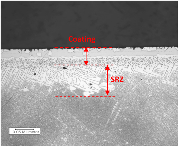
An SRZ is created between the coating and a high Re containing Ni based superalloy
A modified version of a β-NiAl bond coat has been developed by Darolia et al. 67 – 71 at GE Aviation using overlay processes such as ion plasma deposition, APS and EB-PVD. The bond coat is predominantly a β phase, and contains (in wt-%) about 20–25Al, 5Cr, 0·25–0·5Zr and/or 0·25–0·5Hf. The bond coat was designed based on the author’s extensive knowledge gained during the development of NiAl based intermetallic alloys for turbine applications.72 – 74 A large library of NiAl compositions is available in single crystal form to evaluate oxidation resistance and TBC coated life. Compositions were selected based on the knowledge of strengthening behaviour in single crystal NiAl to develop an oxidation resistant and ‘strong’, creep resistant bond coat. Thermal expansion data were used to match thermal expansion of the coating with the underlying substrate. Reactive element doped NiAl coupons coated with TBC and tested to spallation failure showed that minor additions of Hf or Zr to NiAl provided substantial increases in the TBC spallation life as seen in Fig. 15. The improvement was linked, in part, to increase in the room and high temperature strengths provided by solid solution strengthening by Cr in solution within the β phase matrix of the coating and dispersions of α-Cr particles, and by the β′-Heusler phase Ni2Al(Hf, Zr) precipitates within the β phase matrix of the coating (Figs. 16– 18). In addition, TGO scale adherence was provided, in part, by Zr or Hf oxide pegging.
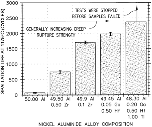
Thermal barrier coating spallation life for TBC coated single crystal NiAl compositions containing small amounts of Zr, Hf and Ti (compositions in at-%) compared with stoichiometric NiAl (50/50)
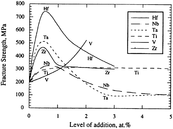
Effects of small amount of alloying additions on the <100> room temperature fracture strength of single crystal NiAl compositions
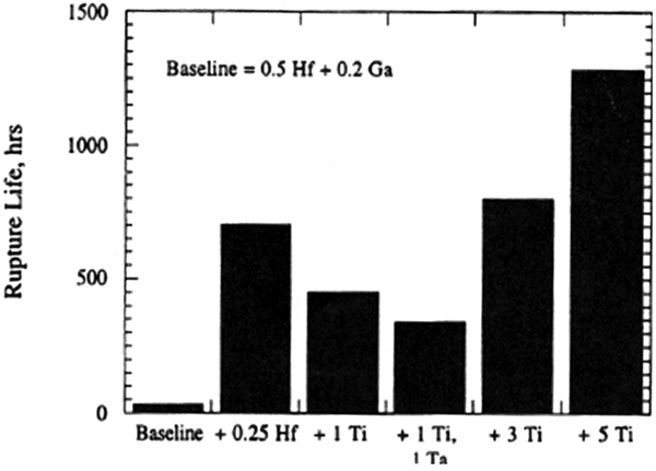
Improvement in rupture strength (life) at 982°C/124 MPa in the <110> orientation with alloying additions such as Hf, Ti and Ta to a NiAl (50Ni–49·3Al–0·5Hf–0·2Ga) single crystal composition. The compositions are shown in at-%
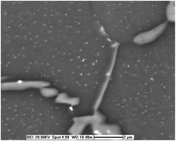
Microstructure of a NiAlCrZr bond coat composition showing Cr particle dispersions and β' precipitates that contribute to strengthening of the bond coat
A programme was initiated to translate the improved performance of the TBC coated NiAl single crystal alloys into bond coat compositions. The result was development of an overlay β phase NiAlCrZr bond coat strengthened to prevent rumpling. As an example, dependence of TBC life in a NiAlCrZr bond coating as a function of Zr content is shown in Fig. 19. Thermal expansion match with the substrate is demonstrated as shown in Fig. 20. In addition to increased oxidation resistance and TBC life in laboratory and engine tests, the bond coat has demonstrated reduced wall consumption of the turbine blade. Reduced rumpling resulted in underlying substrate running cooler by maintaining a smooth air flow boundary layer on the surface (Fig. 21). The NiAlCrZr bond coat has been introduced in GE Aviation’s new engines such as GEnx for the Boeing 787 Dreamliner airplane.
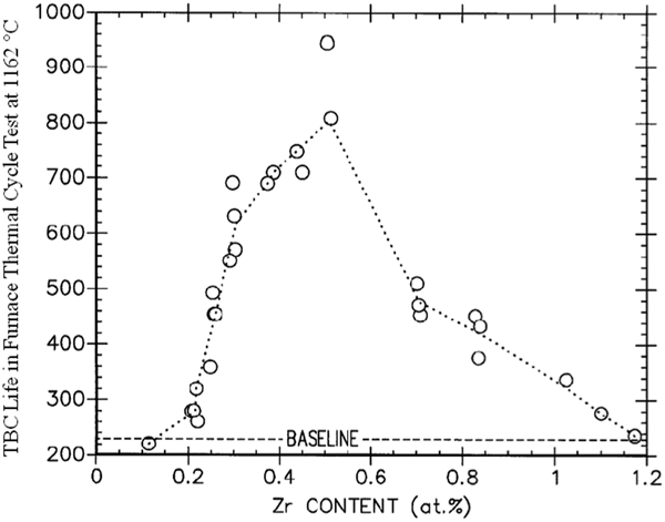
Thermal barrier coating spallation life results from furnace thermal cycle testing of NiAlCrZr coatings produced by EB-PVD method as a function of Zr content68
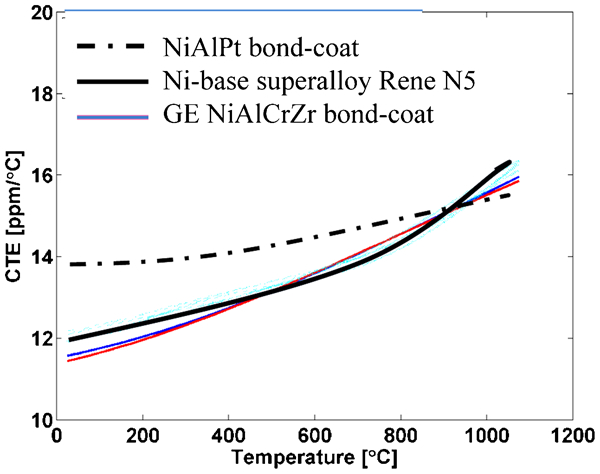
Coefficient of Thermal Expansion match between a second generation single crystal Ni based superalloy (Rene′ N5) and NiAlCrZr bond coat (courtesy Professor Kevin Hemker, JHU, unpublished work)
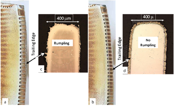
Engine test results with NiAlCrZr bond coat compared with NiAlPt bond coat. a NiAlPt bond coat and b NiAlCrZr bond coat. Bond coat rumpling seen in the NiAlPt bond coat c is absent in the NiAlCrZr bond coat d. Lower oxidation in the NiAlCrZr bond coat and retention of γ+γ' structure in the underlying superalloy was also observed
Diffusion barriers
Owing to increased interdiffusion expected in higher temperature applications, and to avoid SRZ formation, extensive development effort has been made to identify diffusion barrier layers applied between the bond coat and the substrate to block interdiffusion. Multilayer bond coats incorporating a combination of diffusion and overlay processes have been evaluated. Diffusion barrier materials have included metallic (i.e. Re and Ru), intermetallic (i.e. sigma and laves phases) and oxides.75 – 78 Majority of the work has been on Ru containing layers. Ru and Re are demonstrated to be effective barriers, but possess poor oxidation resistance. Alloying to adequately impart oxidation resistance to Ru and Re has not been demonstrated. Oxide barriers have durability issues during thermal cycling. So far, a diffusion barrier layer that meets all of the critical requirements, namely, good adhesion (due to thermal expansion difference), oxidation resistance (or does not oxidise such as an oxide layer), TBC durability during thermal cycling and practical and cost effective processing is yet to be developed, and continues to challenge materials scientists.
Thermal conductivity lower than YSZ (low κ TBC)
There is a significant design benefit in lowering the thermal conductivity and density of the top coat to reduce parasitic mass of the coating especially on the rotating parts such as turbine blades. For higher gas path temperatures, thicker coatings required to maintain constant metal temperatures are undesirable. Hence, considerable effort has been directed for the last two decades towards reducing thermal conductivity by one-third to one-half. Thermal conductivity κ (W m−1 K−1) is often calculated from measurements according to the formula κ = αρC p, where κ is the thermal conductivity, α is the thermal diffusivity measured by a flash diffusivity measurement technique, ρ is the density of the coatings and Cp is the specific heat.
In addition to the composition of the starting material, thermal conductivity is highly influenced by the density and microstructure (e.g. defect structure, porosity, grain boundaries/interfaces, splat boundaries in APS TBC and second phases) of the coating. It is also important that the deposited microstructure, with the optimal porosity level, defect structure and interfaces, be stable during high temperature exposures during the engine operation. Some of the highest thermal conductivity reductions have been achieved with highly porous microstructures. Thermodynamically unstable structures experience a loss or redistribution in vacancy concentration, and coarsening of micropores as well as sintering during exposure. Such changes cause increase in thermal conductivity by reducing the number of microstructural sites available to scatter the thermal wave (phonons). Approaches to lower the thermal conductivity have included the following: YSZ composition modifications including partial or total substitution of Y2O3 by codoping with rare earth oxides to increase crystalline lattice disorder and oxygen vacancies by varying the type and amount (i.e. ionic radius or mass) of stabilisers; process modifications for microstructure changes including porosity increase; and alternate ceramic systems: the efforts have been mainly focused with plasma spray processing since most alternate ceramic compositions are difficult to deposit uniformly by EB-PVD. Excellent reviews of the scientific basis for approaches for reduced conductivity are provided by Klemens and Gell,79 Clarke80 and Mévrel et al. 81 Before we discuss the progress made with these approaches, the author would like to point out the lessons learned directing this effort over 20 years.
Different top coat ceramic compositions result in different as deposited microstructures and density, and it is difficult to separate composition and microstructure effects. Therefore, claims for lower thermal conductivity with a given composition should be analysed carefully. The theoretical/intrinsic thermal conductivity of YSZ is approximately 2·2 W m−1 K−1 and is linked to its composition and phase structure. It is the processing induced microstructure, porosity being a major contributor, that causes a 25–50% reduction in conductivity from the theoretical value. In case of EB-PVD, processing parameters such as surface preparation, substrate temperature, processing temperature and chamber pressure including oxygen partial pressure, and deposition rate, angles and rotation significantly affect microstructure (e.g. volume fraction, geometry and distribution of the pores, column gaps and interfaces).82 – 86 It should be mentioned that the conductivity of APS TBC can be as low as 0·8 W m−1 K−1, the splat boundaries being major contributor for reduction.
The alternative oxide stabilisers to ZrO2 have, in most cases, vast vapour pressure differences as shown in Fig. 22 (reproduced from Schulz et al.87). The vapour pressure difference yields undesirable layered and non-uniform microstructures, at least in the case of EB-PVD processing. Dual source processing and other processing advancements can overcome this issue, in turn, adding to complexity and cost.
It has been demonstrated that the ‘low κ TBC’ compositions, unlike YSZ, do not ‘bond’ to TGO. Lower interface toughness is considered to be the cause, though, further studies are warranted. This lack of bonding requires a YSZ ‘bonding’ underlayer below the new ceramic top coat. This requirement adds to processing steps and associated process reliability, and cost. This is certainly an undesirable requirement.
The particle erosion and impact resistance of baseline YSZ, discussed in the section on ‘Erosion and impact damage’, need improvement based on field observations. Unfortunately, the ‘low κ TBC’ compositions have demonstrated, in most cases, inferior resistance assumed due to their reduced fracture toughness. Understanding the relationship between impact resistance, composition and processing will be key to developing a well balanced, next generation ‘low κ TBC’.
There is significant scatter and error in the laser flash diffusivity measurements primarily due to errors in thickness and density measurements. Therefore, reported thermal conductivity values are sometimes suspect.
Microstructural and phase stability will become important issues when TBCs are used at higher engine operating temperatures. Phase stability of new TBC compositions has been studied by Rebollo et al.,16 Cairney et al. 88 and Kakuda et al. 89 During use at the operating temperatures of ∼1200°C, the feather-like features of EB-PVD coatings progressively disappear and transform into a microstructure of dispersed pores. Additionally, the columns join together to form blocks separated by cracks perpendicular to the interface. These so called ‘aging’ effects have been shown to increase thermal conductivity.90,91 Loss of strain compliance leading to TBC spallation is also a critical issue.
Radiative heat transfer from the gas, currently a minor contributor to the blades, could significantly increase in higher temperature turbines. Development of erosion and impact resistant reflective layers will become an area of future development.
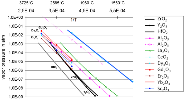
Vapour pressures of various oxides for potential additions to zirconia (Schulz et al.87)
Yttria stabilised zirconia composition modifications including codoping with other stabilisers
Incorporation of Y2O3 to the ZrO2 fluorite crystal structure creates a defect structure (solute Y atoms and oxygen vacancies). In baseline YSZ, one oxygen vacancy is created for every two yttrium cations. The amount and stability of this defect structure and the porosity created during deposition control the as deposited and exposed thermal conductivity acting as phonon scattering centres. In baseline YSZ, the easiest approach would be to vary the Y2O3 content.
Substitution and addition of ternary and high order dopants of metal (M) oxides of the form MO, MO2 or M2O3 with varying ionic radius or atomic mass have been evaluated while maintaining the t' phase. There are over 50 issued patents related to low conductivity with subtle differences in compositions and processing. Developments with the most relevance, uniqueness and impact are discussed next.
Numerous codoped YSZ compositions have shown lower thermal conductivity. One of first research to lower thermal conductivity conducted with ceria stabilised zirconia (CeSZ) as an alternate to YSZ or added to YSZ demonstrated lower thermal conductivity.92 Processing due to vapour pressure differences and inferior erosion resistance has been major issue on the ceria containing TBC. In spite of this limitation, development in this area is continuing.87 Rickerby and Tamarin,93 Nicholls et al.,94,95 Rigney and Darolia96 and Schulz et al. 97 have investigated dopants such as NiO, MgO, CaO, Nd2O3, Gd2O3, Er2O3,Yb2O3, Dy2O3, CeO2, SrO, Sc2O3, Eu2O3, Fe2O3, In2O, Sm2O3, Ho2O3, HfO2 and Ta2O5 with various combinations and levels. Majority of these dopants have shown to reduce thermal conductivity from about 25 up to 40%. A clear trend, however, of the effects of ionic radius and/or mass of the dopants is difficult to establish due to scatter in data, mainly due to processing difficulties, microstructural differences in the as deposited coatings and errors associated with conductivity measurement techniques.
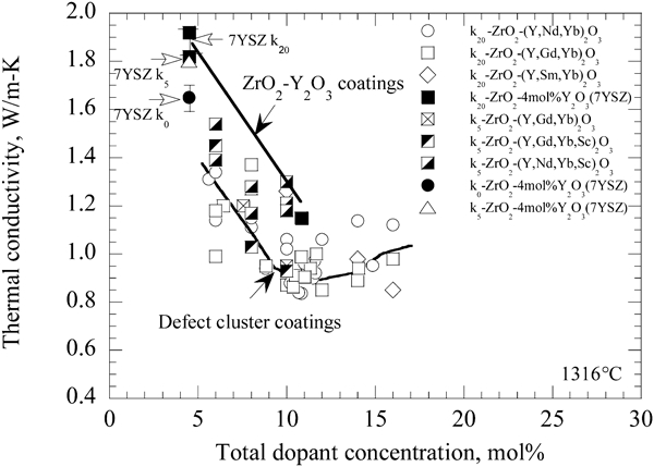
An interesting ‘multicomponent defect cluster’ concept investigated by Zhu and Miller98 – 101 has also shown to lower thermal conductivity. Thermal barrier coatings with oxides clusters of ZrO2–Y2O3–Nd2O3–Yb2O3 (Gd2O3, Sm2O3 and Sc2O3) have been investigated on both plasma sprayed and EB-PVD coatings. In one study, the effect of the cluster dopant type with compositions ranging from YSZ only, YSZ plus a single Nd2O3 or Yb2O3 dopant, YSZ plus both the Nd2O3 and Yb2O3 in varying relative concentrations was investigated. It was observed that ZrO2–Y2O3 with paired dopant additions (Nd2O3+Yb2O3) had lower thermal conductivity than those of YSZ, or YSZ with a single cluster dopant, Nd or Yb. The coatings with equal amount of cluster dopants (Yb2O3/Nd2O3 = 1) often showed the lowest conductivity at a given total dopant concentration. Optimum dopant concentration was established at ∼10 mol.-%. The results of their findings are summarised in Fig. 23. The TEM observations indicated nanoscale clustering of the smaller and larger cations in different regions, with Y being uniformly distributed. It has been postulated that the clusters contribution to the phonon scattering is responsible for larger reductions in conductivity than those found with Y alone or codoped with only one of the cations at comparable total dopant concentration. Higher thermal stability and TBC thermal cycle life comparable to that obtained with YSZ TBC have been shown.
Yttria stabilised zirconia with HfO2 additions
Yttria stabilised zirconia compositions containing hafnia have also been evaluated by Peters et al.,4 Zhu and Miller,102 Gorman et al.,103 Singh et al.104 and Matsumoto et al.,105 since the crystal lattice of zirconia and hafnia is isomor phous, and a complete solubility exists. Yttria stabilised zirconia ingots generally contain about 1–2 wt-% hafnia. Larger additions of hafnia (e.g. 40 wt-% zirconia+40 wt-% hafnia+20 wt-% yttria) further reduce thermal conductivity but the largest effect of 30% reduction at high temperature was reported for zirconia free 27 wt-% yttria stabilised hafnia.104 The latter showed a much denser and fine columnar microstructure and was less susceptible to sintering. Similar favourable lower shrinkage rates have been found for EB-PVD 7·5 wt-% yttria–hafnia samples that were not rotated during deposition. Peters et al. 4 have demonstrated similar results with 32 wt-% yttria–hafnia without notable processing problems with nearly the same composition in both ingot and coating.
Pyrochlore type (A2B2O7) structures
Unlike the t' YSZ based compositions, a new class of low conductivity compositions based on the pyrochlore type zirconate structure [(Gd, Eu, Sm, Nd, La)2Zr2O7] have emerged, of which Gd2Zr2O7, La2Zr2O7 and Sm2Zr2O7 have been studied the most.106 – 110 Conductivity reductions up to 50% have been reported. In addition to lower conductivity, Gd2Zr2O7 TBC has been claimed to provide calcium–magnesium–alumino-silicate (CMAS) attack mitigation,111 though, independent verification and understanding of this benefit is yet to be conducted. Several other beneficial attributes include phase stability up to at least 1500°C,16 and sluggish sintering kinetics.109,112 Some of these compositions are rather difficult to deposit, especially by EB-PVD, uniformity of composition and microstructure being the major issue.109 Owing to chemical incompatibility with TGO, a thin, about ∼25 to 50 μm, underlayer of YSZ is necessary113 to negate reduced TBC life times observed with a just a pyrochlore type zirconate top coat layer. Such underlayers have been reported for majority of ‘low κ TBC’ compositions.4,114 Thermochemical compatibility issues between alumina and ZrO2–Gd2O3 are discussed by Leckie et al. 115 and an assessment of the thermodynamic parameters in the ZrO2–Y2O3–Al2O3 system is provided by Fabrichnaya and Aldinger.116 Significant conductivity reductions have been reported by Vassen et al. 109 on zirconate variations such as La1·7Dy0·3Zr2O7, La1·4Gd0·6Zr2O7, La1·4Eu0·6Zr2O7 and La1·4Nd0·6Zr2O7 applied by APS.
To negate conductivity increase during service, Darolia et al. 117,118 have evaluated combinations of one or more dopant oxides for conductivity reduction along with carbides such as YbC2, NdC2 and LaC2 of the dopant metals which are either evaporated from a carbide ingot source or formed by reaction during or after the EB-PVD processing. In another approach, insoluble alumina by Rigney and Darolia,119 or alumina combined with lanthanum oxide, chromium oxide and/or yttrium chromate by Ackerman et al. 120 have been evaluated. Insoluble particles or dispersions in the TBC structure provide additional sites for phonon scattering as well as stabilise the structure during subsequent exposure.
New ceramic compositions
Other suggested compounds121,122 with very limited conductivity data as a coating are: hafnates such as La2Hf2O7, monazites such as LaPO4, magnetoplumbite structures such as LaMgAl11O19 and LaLiAl11O18·5, garnets such as Y3AlxFe5−xO12, Y3Fe5O12, W3Nb12O44, mullite, TiO2, ZrSiO4, ZrTiO4, perovskite structures such as SrZrO3, BaZrO3 and rare earth aluminates such as RE2SrAl2O7.122 Of these compounds, CaxMg1–xZr4(PO4)6 (abbreviated as CMZP) has been reported with a conductivity of 0·7 W m−1 K−1 at 1000°C.123 Perovskites (ABO3) can accommodate a wide variety of different ions in solid solution including ions with large atomic mass. Some of these compounds are stable to very high temperatures, and have the potential to be developed as future low conductivity materials. Processing as a coating with controlled uniform composition, however, will be a serious challenge.
An excellent summary of reported thermal conductivity data is provided by Levi,1 and reproduced in Fig. 24. There appears to be a minimum value obtainable around 610 wt-% of the total stabiliser additions. Thermal barrier coating life as determined in furnace thermal cycle tests superimposed in the ZrO2–Y2O3 phase diagram by Levi is shown in Fig. 25. It is interesting to note that the TBC life has a maximum value around 6–10 wt-% of the total stabiliser additions (irrespective of the type of stabiliser) to ZrO2. Non-transformable tetragonal (t') phase is the predominant phase in this composition range.
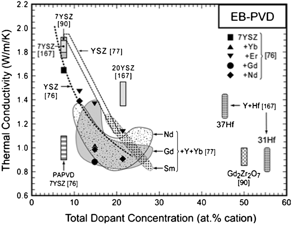
Comparative summary of thermal conductivity values for EB-PVD coatings reported in the literature for a variety of zirconia based materials (Levi1)
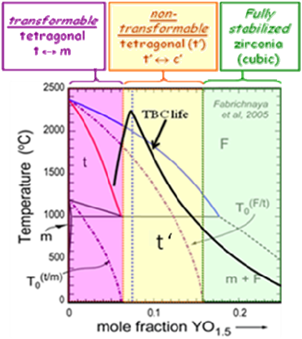
A line representative of the cyclic durability of TBC is superimposed on a binary phase diagram for the ZrO2–YO1·5 showing phases expected (courtesy of Levi, UCSB)
Processing modifications
Processing modifications to incorporate porosity is the easiest approach to reduce the thermal conductivity of YSZ. However, the porosity reduction is only effective if the porosity is retained via improved sintering resistance. For EB-PVD, in addition to porosity within the columns, their feathery structure and gaps between the columns play a significant role. For APS, splat boundaries which are essentially perpendicular to the heat flow cause conductivity reductions as low as 50% of fully dense YSZ in contrast to ∼30% for EB-PVD YSZ. The EB-PVD processing parameters that have been demonstrated for microstructure modifications include the following:
pressure during processing
oxygen partial pressure
part temperature during preheat
part temperature during coating
alternate part motions
bond coat roughness/texture.
It must be pointed out that high temperature exposure during service will densify the coating structure via pore coarsening and sintering, negating the porosity effect. Thermal barrier coating durability for majority of new TBC compositions under thermal cycling is reduced and the erosion rate is increased. The decreased performance has been attributed to lower toughness rendering the system susceptible to delamination internally in the TBC upon thermal cycling.8 Non-compatibility with TGO is also a major contributor.
Thermal barrier coating damage and degradation mechanisms
Thermal barrier coating failures are generally classified into two categories: thermal cycle dependent failure, termed ‘intrinsic failure’ and temperature independent failures, termed ‘extrinsic’ failure which is caused by particulates in the gas turbine environment leading to top layer thinning, densification, cracking and complete loss/spallation. At temperatures >1200°C, CMAS particles can deposit onto the TBC surface, melt and penetrate the TBC structure, changing the near surface mechanical properties and enhancing the TBC spallation tendency. A schematic of various degradation modes proposed by Evans et al. 8 is shown in Fig. 26. The various degradation modes are described in the following sections.
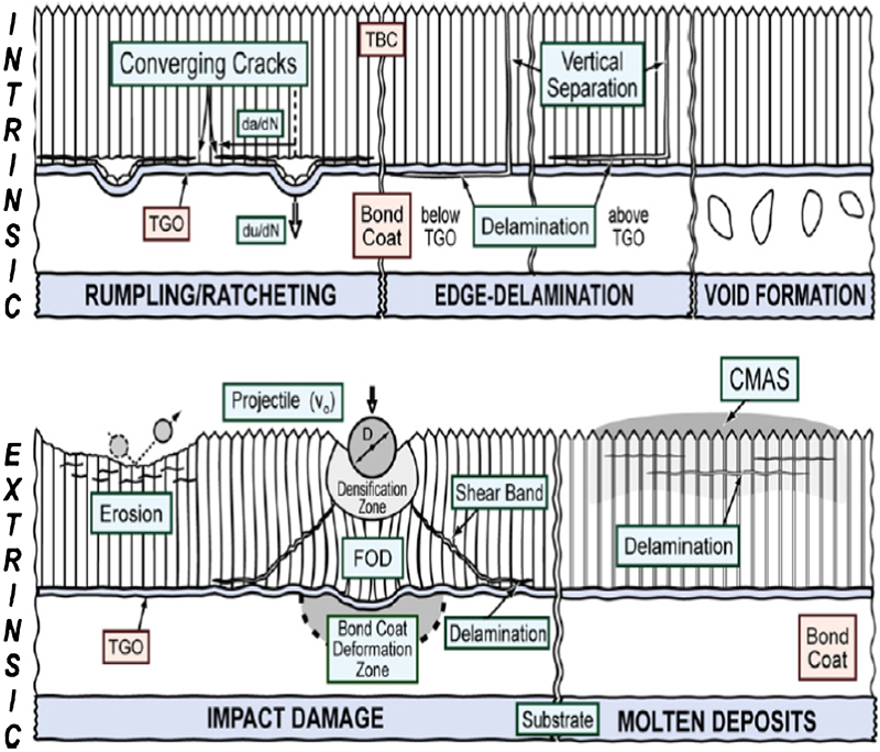
A schematic of various degradation modes proposed by Evans et al. 8
Temperature and thermal cycle dependent failure
Not surprisingly, engine thermal cycles (e.g. temperature, dwell time, rates of excursions, gradients and cycling frequency) play a significant part in TBC failures. The oxidation of the bond coat results in the formation and growth of the TGO that induces stresses and displacements at the TGO/TBC/bond coat interfaces eventually leading to TBC spallation. Extensive research has been carried out to establish the various mechanisms and factors that control TBC spallation in both EB-PVD and APS TBC.124 – 144 In spite of over 50 publications on this subject, arguments still persist. The relative roles of plasticity of TGO and the bond coat as well as phase transformations in the bond coat due to Al depletion are still being debated. During engine operation, several interrelated thermal cycle dependent phenomena take place. The wide variation of engine operating conditions is one of the reasons why TBC failure mechanisms are not completely understood and agreed upon. Additionally, TBC in service is a very dynamic system with continuously changing composition, crystalline phases and microstructures. These changes lead to changes in physical and mechanical properties, so creating models becomes rather difficult. The other complicating factor is that current TBC systems show a wide distribution in life, with a significant proportion failing at much earlier times primarily due to processing variations, and sometimes lack of adequate process control. Additionally, the bond coat surface gets contaminated with a minute amount of impurities such as S, originating from the raw materials or by diffusion from the underlying substrate. The incidence of lower life TBC is avoidable with better raw material control and cleaner heat treat furnaces. Laboratory furnace and rig tests used as screening tests, unfortunately, are not generally simulative of engine operating conditions that are difficult to duplicate in laboratory settings.
A brief summary of our understanding of the factors that control thermal cycle dependent TBC spall in case of EB-PVD TBC with a β phase NiAlPt bond coat follows. The failure mechanisms for the EB-PVD TBC with MCrAlX bond coat and APS TBC differ somewhat,132 and will not be elaborated in this paper. The TGO thickens with time at operating temperature resulting in a constrained volume expansion that leads to inplane compressive ‘growth’ stresses. Additionally, upon cooling, the thermal expansion mismatch with the substrate leads to very high ‘thermal’ compressive residual stresses in the TGO reaching about 3–6 GPa at ambient temperature. During thermal cycling, TGO seeks to relieve compression, by means of out of plane displacements, preferentially into the bond coat since it is relatively soft at high temperature, and prone to creep deformation. During repeated thermal cycling, progressive roughening of the bond coat/TGO/top coat interfaces occurs due to cyclic creep of the bond coat as shown in Fig. 27. Such roughening/undulations are often termed ‘ratcheting’, ‘rumpling’ or ‘bucking’, though, arguments have persisted on the exact terminology. Once the stored energies at the TGO/TBC/bond coat interfaces exceed a threshold value, cracks and separation occur. Initial surface imperfections and rough bond coat surfaces are considered to be contributing to the out of plane stresses, and are the origins of initial displacements and cracks. Large scale buckling of TBC and spallation is preceded by smaller cracks that extend and grow either at the TGO/bond coat or TGO/TBC interface, though, separation within the TGO, and within the TBC at the TGO/TBC interface is often observed.
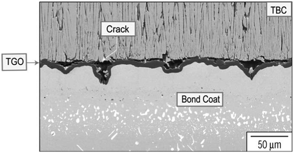
Thermally grown oxide undulations referred to as rumpling or ratcheting in a thermally cycled TBC (YSZ top coat and NiAlPt bond coat)
The growth of the TGO and interdiffusion between the bond coat and the substrate results in the depletion of Al in the bond coat. The Al depletion can promote the formation of other oxides, such as Ni containing spinels, that accelerates localised oxidation by providing fast oxygen diffusion paths. Al depletion also leads to phase transformations such as β to γ' and/or martensite formation (for a β NiAlPt bond coat). Large stresses generated due to transformations in the bond coat have been suggested as contributing factors in promoting undulation growth. Thus, thermal cycling combined with TGO stresses, strain misfit (due to thermal expansion and phase transformations), bond coat creep deformation and initial imperfections leads to TBC failure. Loss of Al by oxidation and by interdiffusion between the bond coat and the substrate also plays a significant role by changing the bond coat properties, and sometimes, creating voids at the bond coat/substrate interface. Several of the concurrent mechanisms operating related to use temperature and thermal cycling during engine service are schematically depicted in Fig. 28 (reproduced from Clarke and Levi2). During the early days of TBC application, TGO thickness of ∼6 μm was considered in industry to be maximum allowable thickness to avoid TBC spallation. Thermally grown oxide thickness up to 17 μm has been observed before failure in the β-NiAl bond coat by Darolia et al. 67 – 71 at GE Aviation. The concept of critical TGO thickness is definitely not a very useful guide since the critical TGO thickness strongly depends on bond coat composition, impurities, microstructure and thermal cycling history.
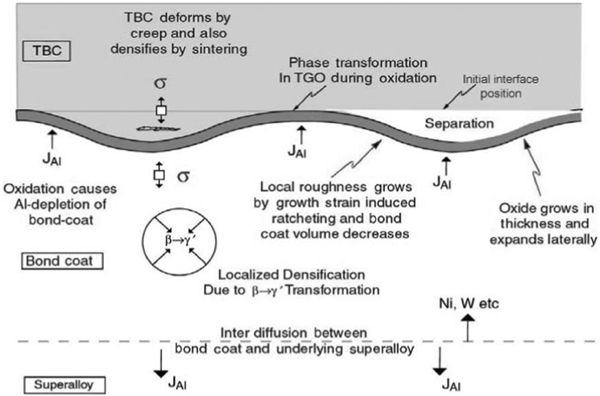
Schematic summary of the several of the concurrent processes occurring in the bond coat, TGO and TBC during use at high temperatures (Clarke and Levi2)
The above scenario suggests the following guidelines for longer TBC life:
Slow growing TGO: Unfortunately this attribute cannot be independently controlled. Thermally grown oxide formation and growth depends on the bond coat composition.
Create and maintain a strong adherence of TGO: It is universally agreed that impurities such as S diffuse to the TGO/bond coat interface and weaken it. Also, rapid conversion to α-Al2O3, and minimisation of other faster growing oxides (e.g. spinels) is essential.
Minimise strain mismatch between the bond coat and the substrate.
Higher yield strength and creep resistant bond coat to avoid rumpling.
Minimal surface imperfections, meaning flat and smooth surfaces.
Bond coat compositions with slow growing TGO and/or can tolerate thicker TGO.
The other temperature dependent TBC degradation is sintering and densification of the porous structure of the top coat resulting in increased thermal conductivity and decreased stain tolerance. Phase destabilisation or changes are not currently limiting issues since TBC operating temperatures are below the threshold of transformation, though, it is becoming an issue for the power generation turbines that run for extended periods of time (e.g. 20 000+ h), metastable phase t' being transformed to the monoclinic phase.
Erosion and impact damage
Thermal barrier coating compaction, plastic deformation, spallation or gradual thinning by particulates in the gas turbine environments generally termed ‘extrinsic failures’ have limited full TBC utilisation. The damage is assumed to be primarily dependent on the microstructure and properties of the top coat. It is quite likely that the TBC/TGO and TGO/bond coat interface properties also play a significant role. For a given TBC system, impinging particle size, mass, velocity, temperature, rotation speed of the component, impact location and incidence angles relative to the specific locations in the component are deciding factors to differentiate between the impact or erosion damage. Particles of various sizes impinge turbine blades at a variety of angles. The leading edge of the blade could experience a 90° impingement whereas the other locations are subjected to particle impingement at lower angles. The impingement angles to the TBC coated turbine combustor liners are about 20° or lower. It has been demonstrated in the laboratory tests as well as during service that the EB-PVD TBC is generally 7–10 times more erosion resistant than the APS TBC in majority of the particle impingement conditions.145 A typical particle size distribution in a dust collected from a high pressure turbine blade is shown in Fig. 29. Particle size ranges from 10 to 100 μm. Sand, ash and dirt ingested are typically smaller in size whereas debris from upstream engine components such as combustor can be of much larger size, and their frequency, fortunately, is low. Different size particles have definite trajectory in the hot flow path rendering impact and erosion damage combined with particle size location specific. Turbine blade locations that are prone to either impact or erosion damage are shown in Fig. 30.
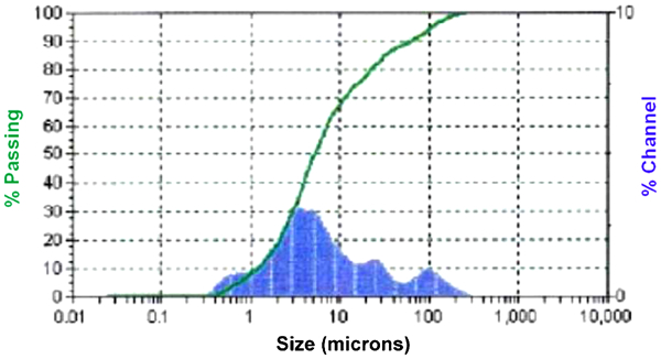
Particle size distribution in a turbine environment
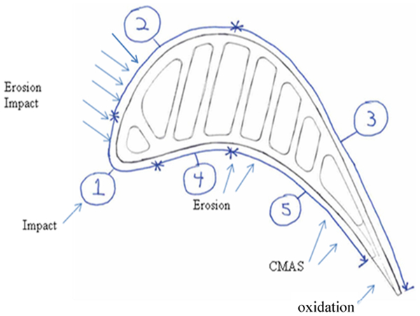
Locations in an HPT blade prone to impact (locations 1 and 2), erosion (locations 2 and 4) and CMAS (location 5). No TBC degradation at location 3
Impacts from ‘large’ particles can cause plastic deformation, kink bands, compaction and brittle fracture of the columns and complete spallation of TBC. Examples of impact damage are given in Figs. 31 and 32. Areas of impact, as noted by compressed and fractured PVD TBC columns, can be seen in Fig. 32, and in some areas shear fractures propagating from the impact site to the bond coat/alumina interface are evident. This fracture, upon reaching the interface, can then propagate along the interface and result in a local spall with an appearance similar to typical thermal cycle spallation. Terminology for this type of damage as ‘foreign object damage’ is misleading since debris from TBC spalled from combustor liners often lands on the blades. An example is shown in Fig. 33. The impact event is unpredictable; however, from field experience, the leading edges on high pressure blades have been found to be susceptible to impact related TBC spallation because of high rotation speed, sharp curvature, relatively higher thermal stresses and their exposure to high velocity particulates. In certain applications, experience has shown that impact related spallation or erosion extends further onto the convex side of the blades. Thermal barrier coating loss at these locations must be accounted for in the design of blades to avoid local hotspots that can accelerate degradation of the underlying bond coat and the superalloy blade. Additional cooling air is required in such locations negatively affecting engine efficiency.
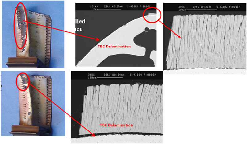
Electron beam physical vapour deposition TBC delamination at a leading edge of an HPT blade by particle impact
Electron beam physical vapour deposition TBC deformation, fracture and delamination in an HPT blade by particle impact
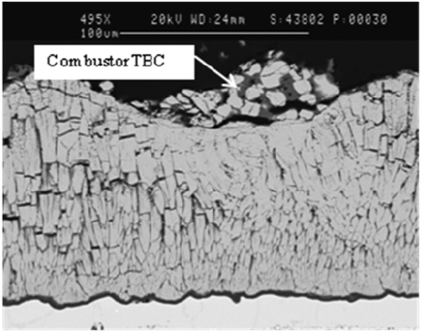
Air plasma spray TBC spalled from combustor can cause impact and erosion damage in EB-PVD TBC applied to a turbine blade
Typical examples of TBC erosion indicated by gradual thinning of TBC are shown in Fig. 34. Erosion/thinning of TBC generally occurs on the pressure side pocket, and on the suction side near the leading edge of the blade. The design of the blade can account for TBC thinning (e.g. thicker TBC) on blade locations susceptible to erosion on the basis of field experience.
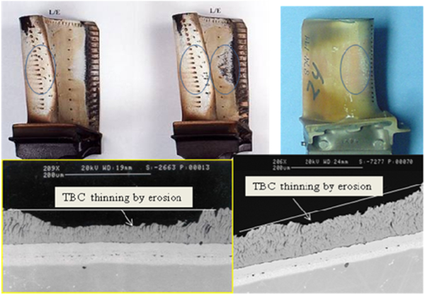
Typical EB-PVD TBC erosion locations and microstructural details of TBC thinning in blade locations indicated by circles
Development of particle impact resistant TBC continues to be a major development activity for a ‘prime reliant’ TBC. The activities have focused on: capability to reproduce the damage modes observed in service in controlled laboratory tests; understanding of the mechanisms of various forms of TBC damage caused by the impinging particles; and improvements in impact and erosion resistance by TBC composition and microstructure modifications.
In order to assess impact resistance under conditions simulative of turbine blades in service, tests developed by Bruce146 at GE Aviation and Wellman et al. 147 – 152 at Cranfied University have evaluated erosion rates and impact events with different sizes and types of particles introduced into the gas stream of a combustor burner rig at high temperatures and high velocities. Progress towards a mechanistic understanding has been limited by the absence of well controlled experiments capable of duplicating the conditions expected in turbine engines. The challenges are associated with the high temperatures (typically 1100°C) and high impact velocities (up to 300 m s−1), as well as the relatively small particles involved (∼20 to 500 μm) and their compositions (usually calcium–alumino-silicate: CMAS). Currently, there are no tests capable of single particle impacts that can reasonably reproduce engine operating environments.
Evans et al. 153 – 155 have analysed the erosion and impact events on field returned blades and laboratory tested specimens. The effort was to establish trends of the material removal rates with the properties of the columnar microstructure EB-PVD TBC. A limitation for creating such models is that the size and velocity of the impacting particles responsible for specific damage sites are unknown. The exact temperature of the component surface during particle impingement is also unknown whenever engine hardware is used for analysis. Other complication arises from the fact that it is unknown whether the damage comprises a single event or an accumulation of multiple events of various energies, though, erosion involves a sequence of nanosecond impingement and TBC thinning.
The analysis has postulated two major damage modes, erosion mode and impact mode, with an intermediate mode in between as described in next sections on ‘Erosion mode’ and on ‘Impact mode’. The transition between the two modes depends on impact velocity, part rotation speed, impact angle, particle size, temperature, contact area relative to the column diameter as well as the TBC constituent properties and microstructure.
Erosion mode
For low kinetic energy mainly with small particles, during initial impact, to accommodate the projectile as it penetrates, elastic stress waves that are transmitted down the columns, can give fracture at tops of columns, at mid-depth and at TBC/TGO interface. For example, induced elastic bending waves can cause preexisting flaws at the column perimeter (e.g. column feathers) to form cracks that extend across the columns, beneath the surface, resulting in an array of column sized cracks (Fig. 35). Once the cracks link, small amounts of material are removed. Elastic waves also reflect off the bottom of the columns becoming tensile waves that propagate back to the surface. These waves could also cause cracks to form and extend across the columns.153,154
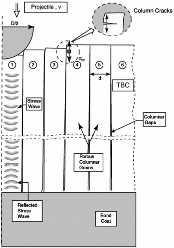
Particle erosion mechanism of crack initiation and propagation with small kinetic energy mainly with small particles
Impact mode
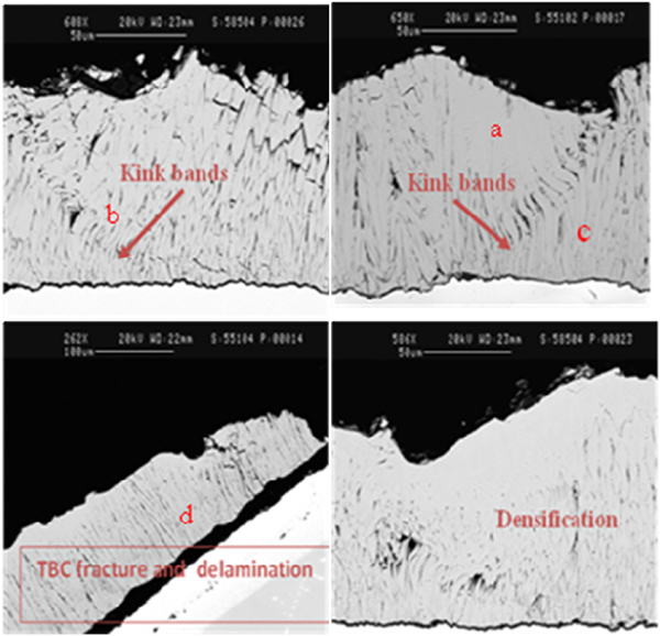
With larger particles, combinations of high kinetic energy and high temperature cause YSZ to be susceptible to large scale plastic deformation and densification around the contact site (Fig. 32a ). Outside the densified zone, kink bands form and extend diagonally downward, toward the TGO interface. Such bands have been identified at a variety of different angles to the interface (Fig. 32b ). Within the bands, the columns are plastically bent, causing the boundaries to crack, weakening the material (Fig. 32c ). In some cases, the bands reach the TGO interface. When this happens, they nucleate a delamination that extends outward from the impact site, along a trajectory within the TBC, just above the TGO. Such delaminations provide a mechanism for creating large scale spalls (Fig. 32d ).
Mechanism maps153 for the onset of material removal by particle impact with the plane indicating the transition from elastic to plastic response superposed are shown in Fig. 36. Evans et al. 153 analysis for initiation and threshold has concluded that increasing the TBC toughness should have the most pervasive influence, through its role in elevating the threshold and, in some cases, decreasing the removal rate (Fig. 35). However, increased toughness may not provide the desired benefit since TBC is quite ductile at temperatures >900°C.156 In fact, doped YSZ with increased toughness, to be discussed next, have not proven to be more resistant relative to baseline compositions in laboratory testing.157 The models also imply that softer materials (at high temperature) should have a substantially higher threshold as well as a slightly lower erosion rate above the threshold. A systematic assessment of the deformation mechanisms and of trends in yield strength with composition and temperature would be beneficial. Additionally, reducing the diameter of the columns should be beneficial in affecting material removal in the elastic range. Designed experiments, preferably using single particle impacts, and further analysis of field returned hardware are required to further aid our understanding.
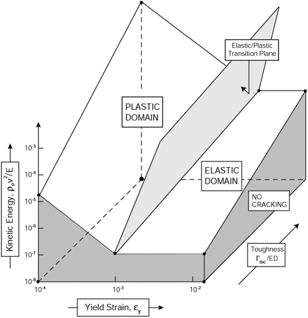
Mechanism maps proposed by Evans et al. 153 for the onset of TBC removal by particle impact with the plane indicating the transition from elastic to plastic response superposed
Approaches for improved impact and erosion resistant TBC
Composition modifications and composite toughening
Low κ compositions
Though lacking in ‘desired’ erosion and impact resistance, YSZ has demonstrated, at least in the laboratory tests with the newer ‘low κ’ TBC compositions, superior particle erosion and impact resistance. Over 200 combinations of compositions and microstructural variations have been tested at GE Aviation under various test conditions to find a low conductivity TBC composition or microstructure with erosion and impact resistance equal to or better than that of baseline YSZ. This effort has generally been unsuccessful except in a couple of cases (composite/layered and modulated structured TBC, discussed later). Wellman et al. 149 have erosion tested ten different TBC compositions under various test conditions including at room temperature and high temperatures. The erosion behaviour of several of the tested low conductivity compositions of doped and codoped YSZ was compared with that of baseline YSZ. Their findings are: all the EB-PVD TBC had an erosion rate lower than that of the APS TBC; aging during high temperature exposure decreases impact and erosion resistance, and becomes more pronounced as the time and/or temperature of aging increases; YSZ is superior to all the ‘low κ compositions’ investigated; and thinner inclined columns are more erosion resistant. Dopant additions to YSZ increase the erosion rate of EB-PVD YSZ significantly as shown in Fig. 37 (reproduced from Ref. 147); this increase is then further magnified when the samples are aged before erosion testing. Engine experiences with the doped YSZ, if any, are considered proprietary, and not available in the open literature.
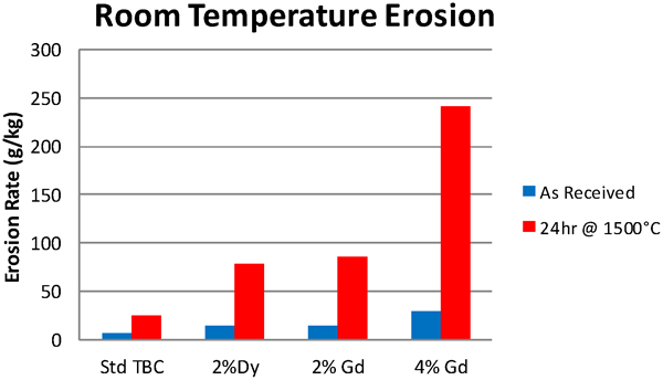
Erosion rates of YSZ modified with Dy2O3 and Gd2O3 (reproduced from Wellman and Nicholls147)
Fracture toughness improvement
The superior erosion and impact behaviour of YSZ is likely related to its higher fracture toughness as shown in Fig. 38 (reproduced from Ref. 8) that compares fracture toughness of zirconia coatings containing different Y2O3 levels. It is interesting to look at fracture toughness data (circa 1983) of YSZ in the single crystal and polycrystalline forms. Fracture toughness was found to be maximum around 6 wt-%Y2O3 as shown in Fig. 10.21 Impact and erosion test data shown in Fig. 39 obtained at GE Aviation158 on TBC coatings show a remarkable resemblance to the fracture toughness plot in Fig. 10. Research activities, therefore, have sought to identify TBC compositions with fracture toughness higher than that of YSZ. A limited number of oxide dopants, generally with tetravalent (Ti4+) and pentavalent (Ta5+) cations can increase tetragonality of zirconia and significantly increase fracture toughness as reported by Kim159,160 by incorporating small amounts of Ta2O5. Greater than twofold increase in toughness at room temperature with substitution of Ti4+ for the larger Zr4+ cation into single phase tetragonal (t′) YSZ increasing the tetragonality of the unit cell has been demonstrated by Schaedler et al. 161,162 Ferroelastic toughening is postulated to be the underlying mechanism for the increase. As mentioned earlier, laboratory testing with these new compositions has not demonstrated any improvement. Fracture toughness measurements at elevated temperatures (about 1100–1200°C) are essential to further elucidate the role of fracture toughness.
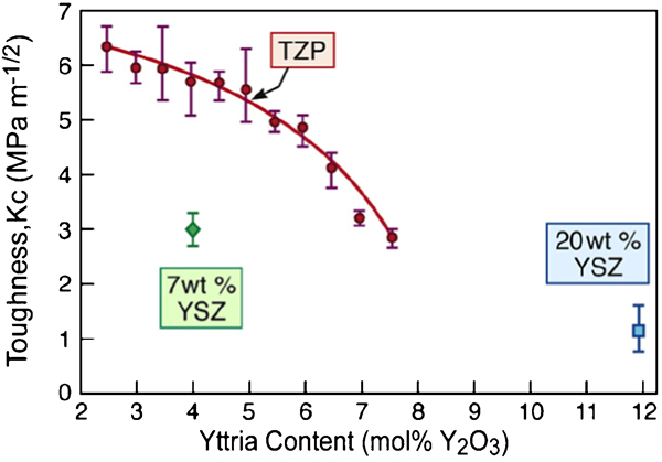
Fracture toughness of 7 wt-%YSZ and 20 wt-%YSZ coating.8 Also shown data for parially stabilised zirconia in the sintered ‘bulk’ form (TZP)
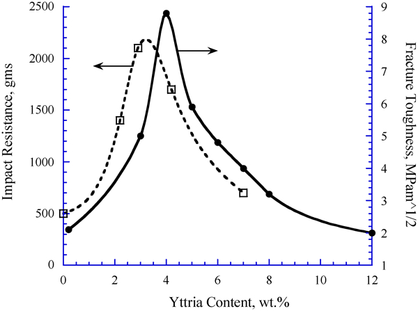
Impact resistance of YSZ coatings containing various levels of Y2O3.158 The fracture toughness data superimposed from Ref. 21
Composite toughening
By incorporating dispersion of ceramic particles such as alumina or chromia in the YSZ microstructure to explore composite toughening, Darolia and Rigney163,164 have demonstrated a 50% improvement in impact and erosion resistance with alumina dispersion. In another approach by Rigney and Darolia,165 the top layer consists of layers of particle free YSZ alternating with layers of YSZ with dispersions of alumina particles.
TGO/bond coat interface toughening
Analytical models have suggested that toughening the bond with the TGO (i.e. interface) should provide benefit in preventing interfacial delamination and complete loss of TBC. Interface strength/toughness cannot be independently controlled. Bond coat composition dependent interfacial chemistry, in particular segregation of impurities such as S, bond has a strong role. Eberl et al. 166 have initiated a difficult task of the measurement of the interfacial properties while Smith et al.167 – 169 have conducted first principles computations of the interfacial adhesion and the role of S and Hf on the interfacial strength: S was calculated to be detrimental and Hf was calculated to be beneficial. Hf was also shown to negate S effect. If S escapes Hf bulk pinning, Hf can mitigate detrimental S effects at the interface. Experimentally, Hou and Priimak53 and Molins et al. 170 have measured S segregation at the TGO/bond coat interface as well as at voids in a NiAl based bond coat composition (44Al–11Pt–37Ni in at-%). S as high as 11 at-% was measured after 50 h at 1100°C as shown in Fig. 40. Hou and Priimak53 have measured interface fracture strength reduction shown in Fig. 41 from ∼80 to ∼10 MPa with 2·5 at-%S at the interface. Experimentally, a large body of literature data exists46,47,51,53 on the detrimental effect of S, and the beneficial effects of reactive elements such as Hf and Y. A fairly recent review of the segregation phenomenon is given by Hou.171 Improved TBC life has been demonstrated by Darolia and Walston172 in Hf containing Ni based superalloys and bond coat compositions.
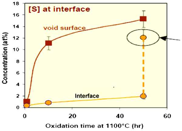
S segregation at the TGO/bond coat interface in a NiAl based bond coat composition: 44Al–11Pt–37Ni in at-%170
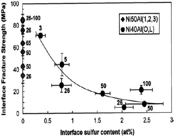
Effect of S on interface fracture strength53
Microstructure modifications
Porosity effect
Porosity effects on performance are not clearly understood due to the fact that porosity levels cannot be independently controlled without changing other subtle microstructural features of porosity such as pore diameter and TBC column characteristics such as column diameter, gaps and the feathery structure. Additionally, these features vary through the thickness of the top coat. Coating chamber pressure, deposition rate, deposition temperature, deposition angle, substrate temperature, surface roughness and rotation speed are some of the EB-PVD parameters that influence porosity. Microstructural modifications have to ensure strain compliance of the top coat; maintain a ‘desired’ thermal conductivity; and minimum susceptibility to microstructural changes during high temperature exposure. Experimentally, denser microstructures have demonstrated inferior erosion resistance.147 Porous coatings absorb the impact much more effectively than dense coatings. On the other hand, increased porosity/softness could have inferior erosion performance. Rapid removal and/or compaction leading to impact mode of damage are the issues. For example, ceria doped YSZ deposits as an extremely soft, friable coating with poor room temperature erosion resistance.92
Other approaches such as smoother TBC surface and dense top layers including metallic layers such as Pt would have limited, short term value in actual engine operating environment, roughening of the surface and spallation of dense layers being the underlying issues.
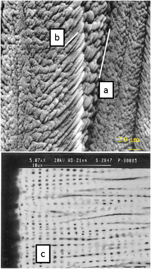
Modulated/wavy TBC structures
A recent breakthrough observation by Darolia et al. 173 from the evaluation of field returned blades showed that a ‘modulated’ (as compared to straight TBC columns) TBC structure can better withstand impact damage as shown in Fig. 42. Evaluation of these blades has shown that the layers between each zone of orientation act as sites for deflection of the impact stress, resulting in removal of only the outer layer(s) rather than the entire coating. In this way, a single layer (perhaps less than 25 μm depending on wave design) is sacrificed rather than the entire coating thickness.
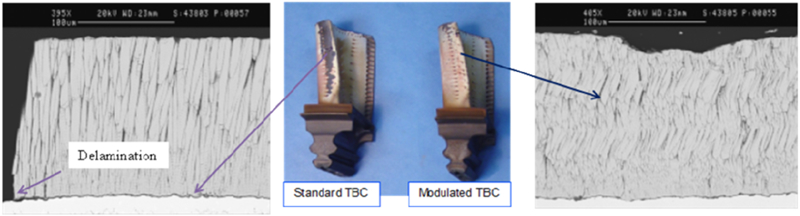
Observations on field returned HPT blades from the same engine service show that modulated TBC structure is resistant to particle impact damage
Deposition, infiltration and reaction with CMAS particles
Under certain engine operating conditions (such as in coastal or Middle East regions), debris of siliceous materials such as airborne dust, sand, fly ash, volcanic dust, concrete dust and fuel residue ingested into the engine accumulate on certain hotter surfaces, generally on the concave side, of the blade, and melt when sufficiently hot. The melt penetrates rather rapidly into the top layer densifying the layer and rendering it susceptible to cracking and delamination. The primary melt constituents are calcium–magnesium–alumino-silicates referred to as CMAS. A typical chemical composition is 35 mol.-%CaO, 10 mol.-%MgO, 7 mol.-%Al2O3, 48 mol.-%SiO2, ∼3 mol.-%Fe2O3 and ∼1·5 mol.-%NiO. This composition melts (

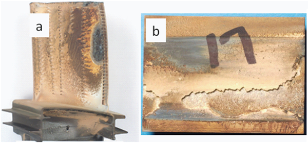
Thermal barrier coating loss caused by CMAS
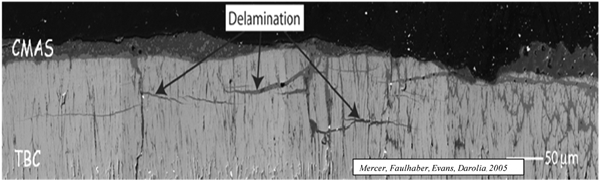
Calcium–magnesium–alumino-silicate penetrated TBC reveals mode I subsurface delamination within infiltrated regions of the TBC, as well as large areas in which the TBC has been entirely removed: covered with yellowish CMAS
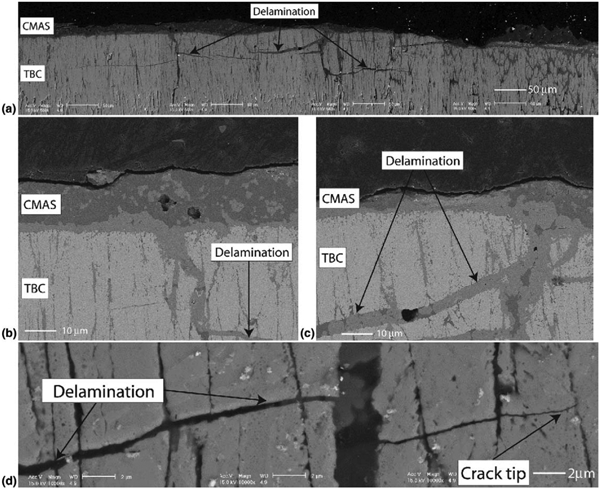
a low magnification backscattered electron image of region with delamination cracks, b backscattered electron image showing phase contrast at interface TBC/CMAS, c backscattered electron image showing phase contrast in CMAS infiltrated crack and d backscattered electron image showing CMAS infiltrated crack. Note that the intercolumnar gaps on both sides of the crack remain aligned, indicating that the delamination is strictly mode I
Thermomechanical effect: Mercer et al.
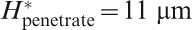
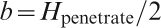
174 have analysed CMAS infiltration caused delamination on field and laboratory tested hardware, and have proposed a cold shock degradation mechanism. A schematic of one of the degradation modes caused by CMAS infiltration coupled with cooling is shown in Fig. 46. The inplane modulus of the CMAS penetrated top coat layer increases by about a factor of 5–10. Such a relatively high modulus of this layer, in conjunction with its relatively low toughness, increases its susceptibility to cold shock during engine shutdown. A shock analysis has identified a critical infiltration thickness 
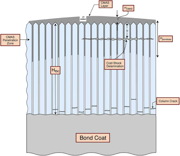
A schematic of a CMAS layer that forms on the TBC and penetrates once it melts. This layer develops a large compressive stress upon cooling to ambient because of the expansion misfit with the substrate. A delamination may be induced near the base of the TBC if the energy release rate associated with the stress in the CMAS layer is high enough
Krämer et al. 175 and Evans and Hutchinson176 have characterised the susceptibility to delamination when penetrated by CMAS on a stationary component, HPT shroud with relatively thick APS TBC, after removal from service. During service, the CMAS melted, penetrated to a depth about half the coating thickness and infiltrated all the open areas. Consequently, TBC developed channel cracks and subsurface delaminations as shown in Fig. 47. Complete TBC spall is also observed in nearby areas. Estimates of the residual stress gradients made on cross-sections (by using the Raman peak shift) indicated tension at the surface, becoming compressive below. A fracture mechanics approach relevant to the thermoelastic stresses upon cooling was used to rationalise the propagation of channel cracks and delaminations.
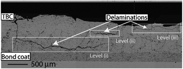
Micrographs of cross-sections through the TBC of a CMAS damaged HPT shroud. Delaminations at three different levels are apparent. In each case, the delaminations originate from channel cracks with separation
Thermochemical effect: Substantial thermochemical attack of YSZ by CMAS occurs at ∼1240°C within minutes. Krämer et al. 177 have observed breakdown of the columnar structure, coarsening, densification and t' phase destabilisation. As seen in Fig. 48, columns have lost their identity in the upper portion of TBC, and are replaced by a conglomerate of much smaller globular particles embedded in CMAS. The reaction zone depth increases with temperature. The chemical interaction involves dissolution of the metastable t' phase and reprecipitation of YSZ that is sufficiently depleted in Y in some locations and susceptible to monoclinic transformation upon cooling, potentially leading to TBC spallation due to volume change associated with the transformation.
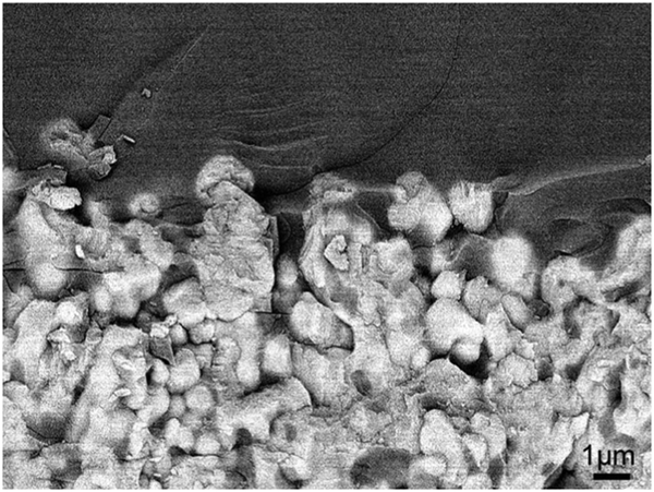
Thermal barrier coating columns have lost their identity in the upper portion of TBC, and are replaced by a conglomerate of much smaller globular particles embedded in CMAS177
In isolated cases, reaction with the TGO has been observed in field returned hardware, leading to TBC spallation (Fig. 49). Near the TGO/TBC interface, the dissolution of the underlying alumina by the CMAS can cause precipitation of a crystalline aluminosilicate phase and globules of a Y enriched cubic YSZ.
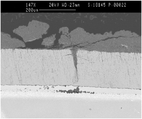
Voiding at base of wedge shaped segmentation crack in a NiAlPt bond coat. Calcium–magnesium–alumino-silicate has penetrated through 50% of TBC thickness
Strategy to mitigate CMAS damage
The engine components have been designed with TBC surface temperatures not exceeding 1240°C until a materials solution to mitigate CMAS damage is available. To address this critical issue that limits maximum use temperature, the CMAS mitigation strategy has consisted of depositing a protective coating on the surface of TBC or incorporating sacrificial materials, mostly oxides, in the strain compliant spaces of the coatings. The sacrificial coating reacts with CMAS to increase the melting temperature or viscosity of the contaminants thereby inhibiting infiltration. One of the examples is alumina either as a top layer or codeposited with YSZ.178 – 181 The other approach is to deposit a dense, non-cracked and non-porous ceramic or metal impermeable or non-wetting outer layer to inhibit the infiltration of molten CMAS. Examples include Pd, Pt, Pd–Ag and ceramics such AlN and BN.
Kramer et al. 182 have shown that dissolution of gadolinium zirconate, Gd2Zr2O7, into the CMAS melt results in a mixture of crystalline phases, an apatite phase based on Gd8Ca2(SiO4)6O2 and the fluorite ZrO2 phase with Gd and Ca in a solid solution, that fills the flow channels, and essentially creates a dense, impervious layer/zone that prevents or significantly slows down further penetration and reaction as shown in Fig. 50. The extent of penetration depends on the relative competitiveness of the infiltration, dissolution and crystallisation kinetics, all of which are dependent on the temperature and the compositions of the melt and the TBC top coat. After an early sealing of the flow channels, reaction continues slowly. The progressive slowing of the attack should be beneficial to the survivability of the reaction layer under thermal cycling conditions. These promising results with gadolinium zirconate have led to evaluation of other rare earth zirconates such as Nd2Zr2O7 and YSZ containing various amounts of Nd2O3. The results have shown their effectiveness in mitigating CMAS penetration by the rapid formation of a dense reaction layer in the intercolumnar gaps and the intracolumnar porosity of an EB-PVD TBC.183 As a further improvement of this approach, Darolia et al. 184 have proposed a two layer system consisting of an innerlayer of YSZ and an outer layer of a pyrochlore structure rare earth zirconate. Yttria stabilised zirconia doped with rare earth oxides of Gd, La, Eu, Sm and Nd have also been proposed as the outer layer.
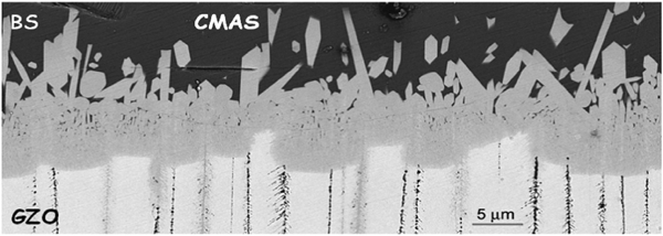
Dissolution of gadolinium zirconate (Gd2Zr2O7) into the CMAS melt results creates a dense, impervious layer/zone that prevents or significantly slows down further penetration and reaction178
Aygun et al. 185 and Drexler et al. 186 have demonstrated that incorporation of 20 mol.-%Al2O3 and 5 mol.-%TiO2 in the form of a solid solution into YSZ (referred to as YSZ+20Al+5Ti) coatings deposited by APS results in resistance to CMAS attack while conventional APS YSZ was fully penetrated and destroyed by molten CMAS (at 1200°C), under the same conditions. The molten CMAS was found to penetrate only about a third of the YSZ+20Al+5Ti TBC thickness before it was arrested due to the formation of crystalline anorthite. It was also demonstrated that the APS Gd2Zr2O7 TBC is resistant to attack by molten lignite fly ash which penetrated only ∼25% of the TBC thickness due to the formation of an impervious, stable crystalline structure that arrested the penetrating molten fly ash.
Darolia and Fu187 have demonstrated that a top layer of Y2O3 or mixtures of YSZ and Y2O3 over a YSZ underlayer reacts with CMAS to produce a yttrium–calcium–silicate phase having a needle-like geometry that is very dense and resistant to infiltration of molten CMAS. These coatings were deposited by EB-PVD without any difficulty due to vapour pressure similarity between ZrO2 and Y2O3.
Scatter in TBC performance
Scatter in TBC test data and engine performance continues to be a major issue as observed in laboratory furnace cycle tests data and in infant mortality (e.g. TBC spall right after coating deposition, occasional TBC failure during rotor grind or during engine qualification test before shipment). Thermal barrier coating life has a wide variation as shown schematically in Fig. 51. Consequently, blade design incorporates only the lower end of the TBC life distribution curve. Weibull statistical distribution curves are also used. Scatter in TBC life data has been attributed to: processing variables; defects (e.g. grits) introduced during manufacture; impurities introduced during coating processing and the from the raw materials; segregation of S and other impurities to the TGO/bond coat interface; surface contamination from the heat treat furnaces; and lapse in process instructions and equipment maintenance. S segregation and resultant reduction in TGO/bond coat interface fracture strength was described in an earlier section. An extreme example of TBC data scatter (tenfold variation in TBC life) is shown in Fig. 52, plotted from a study by Darolia188 to pinpoint various sources of TBC data scatter. Thermal barrier coating specimens having identical substrate, bond coat and top coat compositions, processing, thickness, and deposited as a single batch were heat treated after the bond coat deposition in several different furnaces at two slightly different temperatures. Another example of variation is shown in Fig. 53. Variation in surface colour in test specimens (with NiAlCrZr bond coat only) arises from varying specimen locations in the deposition chamber using the same evaporation target. The coating depositions were aimed to have identical NiAlCrZr bond coat composition.
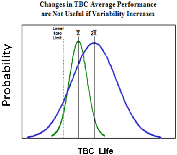
A wide variation is seen in TBC thermal cycle test life in laboratory testing. The component is designed to the low end of the life data. New TBC compositions need to reduce variability as opposed to aiming for higher average life
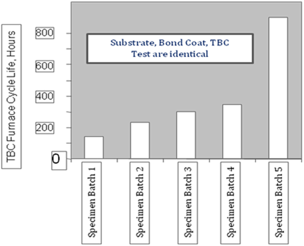
Scatter in TBC life with identical specimens (substrate, bond coat, top coat, processing and tests are identical). Variation comes potentially from post-deposition heat treatment conditions (furnace type, contamination from furnace walls, temperature and vacuum level)
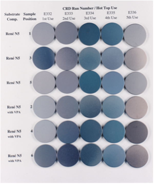
Thermal cycle furnace test buttons (with NiAlCrZr bond coat only) show variation in surface colour arising from specimen locations in the deposition chamber using the same evaporation target. The coating depositions were aimed to have identical NiAlCrZr bond coat composition
Coating process improvements need to focus on variability, not just average performance. An opportunity exists for utilisation of inline sensors during processing at the risk of added cost. The contaminants such as S and C at ppm levels can vastly affect TGO growth and, therefore, TBC life. Unfortunately, these impurities are difficult to measure and accurately control at the ppm level in a production environment. To inhibit such degradation, there has been a long history in the industry of systematically lowering the S level in superalloys, as well as using alloy additions such as Y, Hf and Pt to tie up remnant S. Continued surface science research to fully understand role of various contaminants, and their synergistic effects would help alleviate this problem.
Thermal barrier coating lifetime prediction
The major challenge in TBC life-time prediction has been to identify laboratory and component tests that can accurately simulate conditions in an operating turbine. Key variables such as temperature, thermal cycle, pressure and thermal gradients are difficult to reproduce in a single test specimen and laboratory set-up. Also, TBC service life is subject to scatter due to differences in operating conditions. Modelling of various failure mechanisms in TBC involves numerous thermomechanical phenomenon with complexities and nuances not found in other materials. At best, the models have incorporated data on bond coat oxidation and TGO growth, and have relied heavily on the vast body of existing knowledge of environmental coatings and their failure mechanisms. Understanding of the TBC damage by particles (e.g. erosion, impact and CMAS penetration) is still evolving. Design of the components has been dependent on physical evidence of damages and their location on the field hardware. This approach has been successful, but under utilises TBC capability.
The current testing protocol for screening candidate materials at GE Aviation typically consists of: furnace cycle test on simple, flat coupons (no gradient); burner rig test with cylindrical specimens without gradient; burner rig test with tubular specimens with gradient; component test with actual parts/geometry; factory engine test; and flight test. Numerous variations of specimen designs and test conditions exist to simulate TBC surface temperature, temperatures at various interfaces, thermal gradients, cycle effect and curvature. Without the gradient in the laboratory tests, test temperatures are limited by the bond coat temperature capability, and thus provide information on the bond coat oxidation driven TBC failures only. Several earlier lifing methodologies were incorrectly derived on the concept of ‘critical TGO thickness’ to TBC spallation with the temperature dependence following Arrhenius kinetics.132 This approach is no longer used because the ‘critical TGO thickness’ is dependent on bond coat composition and on a variety of test conditions such as thermal cycling frequency and specimen geometry. The current models are incorporating TGO growth rate with the stored strain energy to predict failure. Only a limited number of thermomechanical tests to represent temperature gradients and strains in the coating have been conducted due to complexity and cost of the test set-up. Test development activities to simulate engine conditions and service observations have continued. Fortunately, TBC life extrapolated from the laboratory data have matched engine experience to a reasonable degree in cases where the failure is bond coat oxidation driven.
Since the TBC surface temperature is designed not to exceed 1200°C to prevent CMAS melting and penetration, TBC sintering and t' phase transformation is not considered life limiting.
A typical particle erosion and impact test as described by Bruce146 simulates only a few of the damage modes observed in an engine, and therefore, not used for lifing purpose. It is used only as a screening test. There is not much available engine experience data on erosion and impact behaviour of new top coat compositions since YSZ has been used exclusively as a top coat. Additional test development including single particle impact is required. Measurement of properties such as hardness and fracture toughness at elevated temperatures will further aid our understanding in this area. A high temperature probe to measure deformation at elevated temperatures has been developed by Watanabe et al. 189 and Bacos et al. 190 at ONERA have developed high temperature microindentation tests that would be useful in this critical area.
There are currently no effective non-destructive evaluation methods used in industry that can act as quality control and/or to monitor remaining life. Progress in this area is being made by Chambers and Clarke,191 Feist et al. 192 and Eldridge et al. 193 In situ measurements of temperature by introducing a minor concentration of a rare earth oxide into YSZ for recording luminescence lifetime have been proposed. Clarke and Gentleman194 have proposed coating layers with a different luminescent ion in each to monitor the wear of the coating by the changes in luminescence as successive layers are eroded away.
Design considerations with TBC
The low thermal conductivity of TBC top coat reduces the temperature of the turbine component metal only when the surface of the component is cooled with backside cooling in a high heat flux environment. Also, because the top coat provides an insulating layer between the combustion gas and the component, the component transient response is slowed down which reduces thermal gradients.
A fairly conservative design is practiced since TBC is considered not ‘prime reliant’ due to the various performance issues discussed in the paper. Heat transfer conditions and temperature profiles with and without TBC at and near the critical and non-critical locations of the component dictate specific locations where TBC is applied and its thickness. To utilise TBC to a greater extent, TBC performance in the field is being analysed and related to laboratory data.
Maximum allowable bond coat temperature based on bond coat capability for a specific engine mission cycle and life requirements and overhaul interval is the first design consideration. Calcium–magnesium–alumino-silicate melting temperature of ∼1240°C sets the upper temperature limit for the top coat. In areas, prone to impact, design has considered the maximum allowable bond coat temperature as the limit to avoid rapid oxidation of the coating and the underlying substrate. In rotating components such as blades, TBC thickness that ranges between 100 and 250 μm is kept to a minimum sufficient to meet mission requirements to avoid excessive inertial loads due to the extra mass. On stationary components, such as shrouds and combustors, the mass is less critical and much thicker layers can be used. Thermal barrier coating thickness on these components can range from 250 to 1000 μm.
Based on the field observations and laboratory experiments, it has been assumed that TBC will eventually fail. Thermal barrier coatings do not provide self-renewing protection. When TBC spalls, the thermal protection is lost unlike environmental coatings used in turbines where a protective scale such as alumina reforms. Thermal barrier coating is stripped off the field returned blades and reapplied if the blade is serviceable. The design practice has considered the following factors: when and at what location of the blade TBC spalls, type of TBC failure mode (thermal/engine cycle related, particle erosion, impact damage or CMAS induced) determined by visual and microstructural failure analysis, and estimated temperature profiles at the damaged locations.
Fortunately, the majority of the failure modes and their specific locations have been reasonably predictable. Temperature rise in the component is calculated at the locations where TBC is missing or thinned out. Design iterations involve TBC spall size or remaining TBC thickness, altered heat transfer and heat flux characteristics. Certain specific locations of the blades (e.g. leading edge) are designed without taking into account the benefit of the insulating properties of TBC, since it is difficult to predict and avoid TBC loss due to large impacting particles. In some cases, the leading edge curvature of the blade has been redesigned to minimise impact damage.
Conclusions and future directions
Application of TBC is one of the major developments in turbine industry that has revolutionised how turbine components are designed. The surface temperatures of the components can potentially be increased by as high as 200°C. The temperature benefit surpasses other material technologies advances including single crystal Ni based superalloys achieved over a 30 year period. Thermal barrier coatings have become an integral part of turbine designs requiring higher efficiency, performance and reduced emissions and noise. Thermal barrier coating applications continue to increase on components in the propulsion and power generation turbines. In future, CMC components will also depend on TBC. Thermal barrier coatings have evolved from just simple insulating layers for temperature reduction to complex designs. However, the turbine designers have a love and hate relationship with TBC because of unacceptable scatter in laboratory and engine performance, even with the baseline YSZ TBC due to a variety of reasons mostly related to processing, and issues related to damage by the particulates in the turbine operating environment. The scatter in performance dictates that turbine components should be designed to the lowest spectrum of the scatter band. Enhanced reliability should lead to deriving greater TBC benefits.
While our understanding of mechanisms governing TBC performance has improved significantly after extensive research and development over the past two decades, no clear top coat composition superior to YSZ has been developed; balance of properties being an issue. The baseline top coat composition developed at NASA continues to be used. It was essentially a mother nature’s gift after a short development effort mainly at NASA based on the knowledge of bulk oxides used in industrial applications.
Modifications to existing EB-PVD and APS processes such as DVC, directed vapour deposition and suspension plasma spray have been developed for process efficiency, cost reduction, and composition and microstructural uniformity, control and flexibility. These processes are increasingly being used. Critical need still exists for better process controls with online sensors to avoid infant mortality, reduce scatter and improve TBC reliability. Higher temperature applications requiring CMAS related damage mitigation as well as microstructure and phase stability will add to composition and process complexity with added costs that will need to be balanced with TBC performance requirements for a specific application.
New bond coat compositions have been developed for slow TGO growth, higher temperature and/or longer service life capabilities, reduced interdiffusion and reduction/elimination of platinum group metals. These newly developed bond coats are being introduced into service. There is still a need to minimise use of expensive elements such as Pt, Re, Ta and Ru. Long term availability of the rare earth elements is also a concern in the industry. Bond coat development effort will continue for further optimisation of TGO and reduced interdiffusion with the newer generation of Ni based superalloys. The maximum bond coat temperature will still be limited by the temperature capability of the underlying alloy since there is minimal thermal gradient between the bond coat and the substrate. Life prediction, validation, and oxidation and hot corrosion tests that simulate engine behaviour will continue to be pursued. Development efforts for effective diffusion barriers will continue. This area could prove to be a holy grail.
The ‘low κ TBC’ compositions will most likely require an under layer of YSZ because of the chemical incompatibility with TGO. This will add to process complexity and cost. The erosion and impact resistance of the ‘low κ TBC’ compositions is inferior to YSZ TBC as demonstrated in laboratory and component tests. Validation of laboratory data with engine tests is required. Currently, limited engine experience exists.
Development efforts have continued to make TBC ‘prime reliant’. Prime reliance will require elimination of coating process variability, consistency in quality and performance over time and a long and predictable life. Calcium–magnesium–alumino-silicate caused damage modes have limited TBC surface temperature to ∼1200°C. Calcium–magnesium–alumino-silicate mitigation solutions are the most critical development needs, and will continue to challenge materials scientists. In author’s opinion, CMAS can become TBC’s Achilles’ heel. Mitigation results with rare earth zirconates are very promising. Validation with engine tests needs to continue. Thermal barrier coating thinning by particle erosion can perhaps be addressed by experience based design practices but impact events are unpredictable, and fail safe designs need to be developed. Further development of tailored TBC microstructures involving multi- or modulated layers should play an important role in combating impact damage caused by impinging particles. Additional test development including single particle impact is required. Measurement of properties such as hardness and fracture toughness at elevated temperatures will further aid our understanding in this area. Embedded thermographic phosphors for temperature and wear sensing will be used for specialised mission critical applications.
The scientific understanding of TBC systems has benefited from collaboration between industry, government laboratories and universities for the last decade. Unfortunately, such collaborations have slowed, at least in United States. The collaborations need to continue because the future TBC systems for higher temperature applications will most likely be highly complex incorporating multifunctional multilayers requiring multidisciplinary efforts. The challenge will be to develop cost effective TBC systems with balanced properties. As the TBC surface temperature is increased, issues such as phase stability, densification and microstructural changes will affect TBC performance particularly, spallation behaviour. Future TBC research will involve, in addition to composition and process development, a better understanding of failure mechanisms, life prediction modelling, more effective use of sensors, perhaps imbedded, and non-destructive evaluation methods for quality control during TBC manufacture, and assessing the remaining TBC life. Improved laboratory and component tests including thermomechanical and thermochemical–mechanical tests simulative of engine operating conditions and associated failure mechanisms will help life prediction and component designs that take advantage of TBC to the fullest extent.
Footnotes
Acknowledgements
This review has attempted to capture contributions of a large number of researchers. I would like to acknowledge many of my colleagues at GE Aviation and GE Global Research, especially Joe Rigney, Scott Walston, Dave Wortman, Ken Wright, Curt Johnson, Don Lipkin, J.-C. Zhao (currently at the Ohio State University), Ming Fu, Mark Gorman and Ben Nagaraj. Collaborations with Professors Tony Evans (University of California at Santa Barbara, UCSB), Carlos Levi (UCSB), David Clarke (UCSB), Kevin Hemker (Johns Hopkins University), Brian Gleeson (University of Pittsburgh), Arthur Heuer (Case Western Reserve University), Jerry Meier (University of Pittsburgh), Fred Pettit (University of Pittsburgh), Dr Bob Miller (NASA), Dr Dongming Zhu (NASA) and Dr Uwe Schulz (DLR, Germany) are greatly appreciated. Dr Steve Fishman (retired, Office of Naval Research) was highly instrumental in University collaborations. Much of my thoughts and insights were obtained from such collaborations. This paper reflects much of the research conducted under these collaborations. Special thanks to Drs Carlos Levi, Richard Wellman (Cranfield University), Uwe Schulz and Dongming Zhu for allowing me to use figures from their published and unpublished work.