
Abstract
Excellent thermal conductivity and lower density make Al–Si alloys a suitable alternative for cast iron in the fabrication of engine components. The increase in the maximum operation temperature and pressure of engines necessitates improving the thermomechanical fatigue performance of Al–Si alloys. This paper has two major parts focussing on the use of Al–Si based alloys in cylinder heads and engine blocks.
In the first part, the structural stress–strain and material property requirements of cylinder heads are discussed. In addition, the physical and mechanical properties of different competing materials used in the manufacture of engine components are reviewed. The physical metallurgy, solidification sequence and thermal conductivity of Al–Si based alloys are reviewed. Also discussed is the effect of microstructural features on thermomechanical fatigue lifetime. This part also includes an overview of the strengthening mechanisms of cast Al–Si alloys, by dispersed phases and heat treatment.
Demands to improve fuel economy and reduce emissions necessitate modifications in the materials and design of engine blocks. Wear resistance and low friction coefficient are the major characteristics required for engine block materials. In the second part, the most promising alternative approaches to manufacturing liner-less Al–Si alloy cylinder blocks are elaborated.
Introduction
To reveal the performance requirements for engine components (engine blocks and cylinder heads), the operating service conditions need to be understood. Three different loads that are applied on the cylinder head have to be considered: the assembly load, the load produced by combustion pressure and the thermal load. The effects of thermal load on the fatigue lifetime of a cylinder head are overwhelmingly greater than those of the other loads. In a start–stop cycle, an engine might be warmed up from 243 K in a cold winter to over 523 K. During such a thermal cycle, large thermal/mechanical loads are applied on the engine components because of non-uniform thermal expansion/contraction of different engine parts.
Over the past decade, Al–Si casting alloys have increasingly been used in the automotive industry as a suitable alternative for cast iron in fabrication of engine components. The major advantage of Al–Si alloys, besides their high strength to weight ratio, is their excellent thermal conductivity, which allows the combustion heat to be extracted more rapidly compared to cast iron. On the other hand, the automotive industry has been ever facing the challenge of improving efficiency and overall performance of engines. To increase the efficiency, the maximum operation temperature and pressure of the engine must be raised. The increase of operation temperature, which leads to softening of hypoeutectic Al–Si alloys, necessitates high-temperature strengthening of the Al–Si alloys.
Hypoeutectic Al–Si alloys equipped with cast iron liners are widely used in the manufacture of engine blocks. The application of liner-less Al–Si alloy cylinder blocks could improve the thermal conductivity and give the possibility of reducing engine size. However, hypoeutectic Al–Si alloys cannot satisfy the required tribological characteristics for engine blocks and it is imperative to fortify the cylinder bore wall by a suitable technique.
Thermomechanical fatigue
The cyclic stresses that cause fatigue failure at elevated temperature (0·3T
m≤T≤0·7T
m) do not necessarily result from the application of external loads; they could also be created by cyclic thermal stresses. Thermal stresses are produced when the change in dimensions of a member, which is in turn the result of a temperature change, is restricted by some kind of constraint. For instance, in a fixed end bar, the thermal stress produced by a temperature change (ΔT) can be expressed as (if no plastic strain):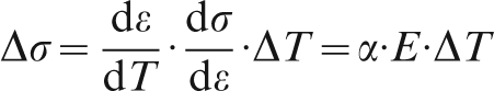
Under thermomechanical conditions, the total strain (ϵtot) is the sum of thermal strain (ϵth) and mechanical strain (ϵmech) components, the latter being composed of elastic (ϵel) and inelastic strain (ϵin) components:
In thermomechanical fatigue (TMF), thermal and mechanical strains with different phasing might be applied to specimens. 3 Two major cycles are generally employed in a TMF test: (a) in-phase cycle, where the mechanical strain and thermal strain are at the same phase (e.g. maximum strain at maximum temperature); and (b) out-of-phase cycle, where mechanical strain is maximum at minimum temperature. Variations of strain components (thermal/mechanical and total strain) with time corresponding to OP TMF (out-of-phase TMF) and IP TMF (in-phase TMF) cases are illustrated in Fig. 1. 1,4
a Out-of-phase and b in-phase thermo mechanical loading 1
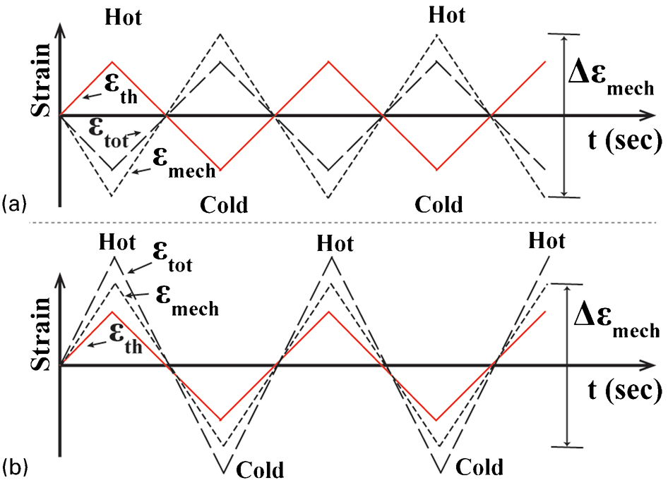
The governing damage mechanism in engine components (e.g. cylinder heads) has been reported to be OP TMF cycles. 5,6 In each cycle of OP TMF, since a specimen crosses a temperature range, it can be affected by a variety of thermally activated processes (as illustrated in Fig. 2). The damage mechanisms can affect the specimen either individually or in mutual interactions. The major damage mechanisms in TMF processes are activated by fatigue, environment (oxidation) and creep. 4,7
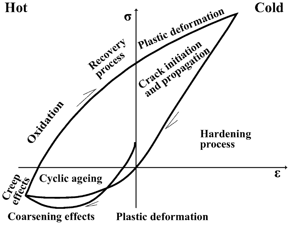
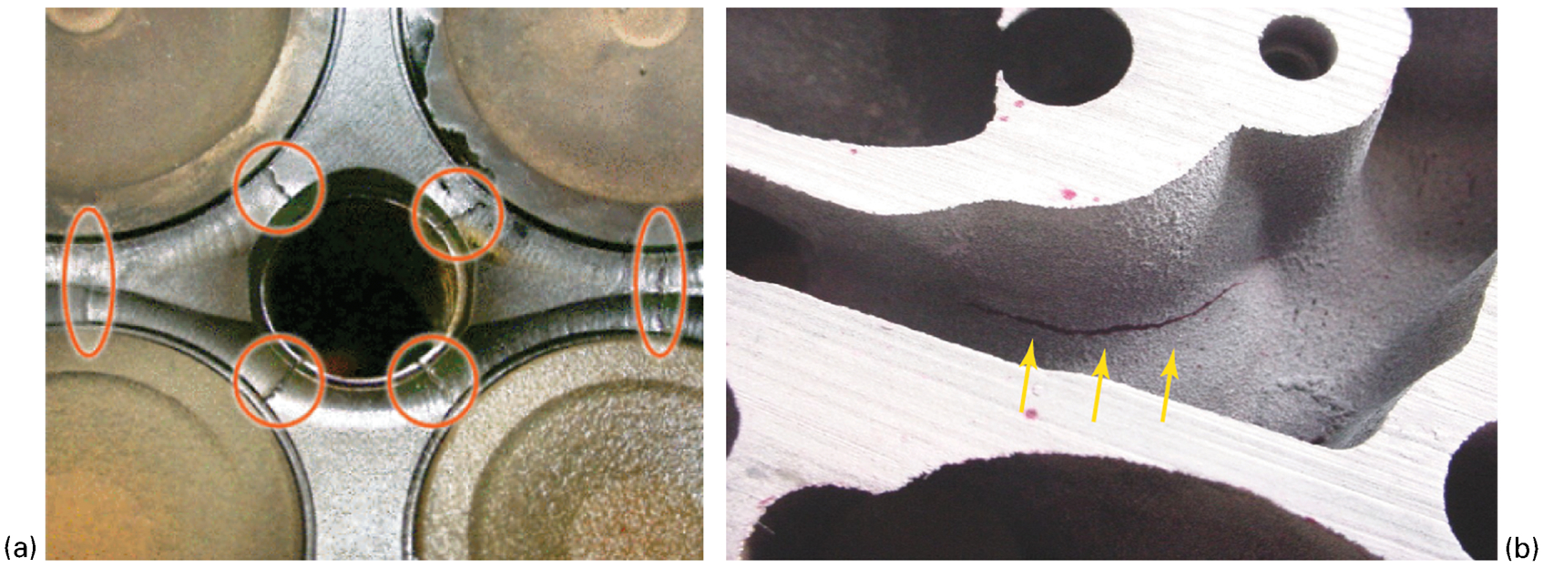
Because of the complex geometry, thermal/mechanical strains in a cylinder head are known to be larger than in an engine block; therefore the former is more susceptible to failure by TMF. Detailed information about geometry, constituent parts and applied conditions on cylinder heads can be found elsewhere. 10,11 Figure 3 shows two pictures of typical crack initiation areas in cylinder heads.
Several studies 13–15 have been done to simulate/measure the thermal/mechanical stress–strain variations and temperature gradient in cylinder heads. As mentioned above, three loads on the cylinder head must be taken into account: the assembly load, the load produced by combustion pressure and the thermal load. The assembly load is generated by the screws connecting the cylinder head to the engine block, press fitting of valve seats and hot plug. The peak firing pressure, which is generated by combustion pressure, can reach values up to 200 bar in diesel engines. 5,16–18 In a start–stop cycle, the engine is warmed up to over 523 K, with a strong temperature gradient being created during operation between the water cooled flame deck (from 373 to 393 K) and the combustion chamber face (from 523 to 573 K). The constraint imposed on thermal expansion creates the most significant operating stresses at the critical flame-face sections of the cylinder head (e.g. valve bridge). The thermal load affects the fatigue lifetime to a far greater extent than the other two loads mentioned. 18–20
Figure 4 illustrates the calculated hoop strain–hoop stress for the first through third hot–cold cycle in the valve bridge area of a cylinder head. At the beginning, assembly loading generates a tensile hoop stress. The stress is compressive during heating, which becomes tensile upon cooling of the assembly. As illustrated, the mean hoop strain is compressive while the mean stress is rather tensile during the temperature cycle. 19,21
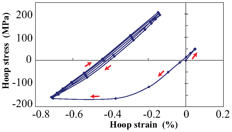
Hoop-stress v. hoop-strain at valve bridge 21
Two distinct fatigue modes control the lifetime of engine cylinder heads: mechanical fatigue and thermal fatigue. Mechanical fatigue, as a high cycle fatigue (HCF) in cylinder heads, is driven by the fluctuation of pressure in the combustion chamber. The thin walls (thickness ∼10 mm), adjacent to the water ducts in the valve bridge of a cylinder head, are the critical locations for mechanical fatigue crack initiation. The temperature range in these areas has been reported to be 393 K (at lower engine speed) up to 443 K (at higher speed). 22 The design of cylinder heads, the intrinsic fatigue strength of the alloy and residual stresses induced by heat treatment are the three major factors, which significantly affect the mechanical fatigue resistance. 22,23 Thermal fatigue, as a low cycle fatigue (LCF), is driven by the start–stop cycles of the engine. The typical thermal stress and strain cycles in the valve bridge (i.e. point A) of a cylinder head are illustrated in Fig. 5. The thermomechanical loading factor K TM = −(ϵmech/ϵth) is ∼0·75 in the cylinder head. It seems that the influence of HCF loadings on the lifetime is small; the typical ignition pressure is less than 200 bar, and the time of the HCF loading occurring is superimposed with the heating period and dwell time during which the stress is compressive. 5,6,8
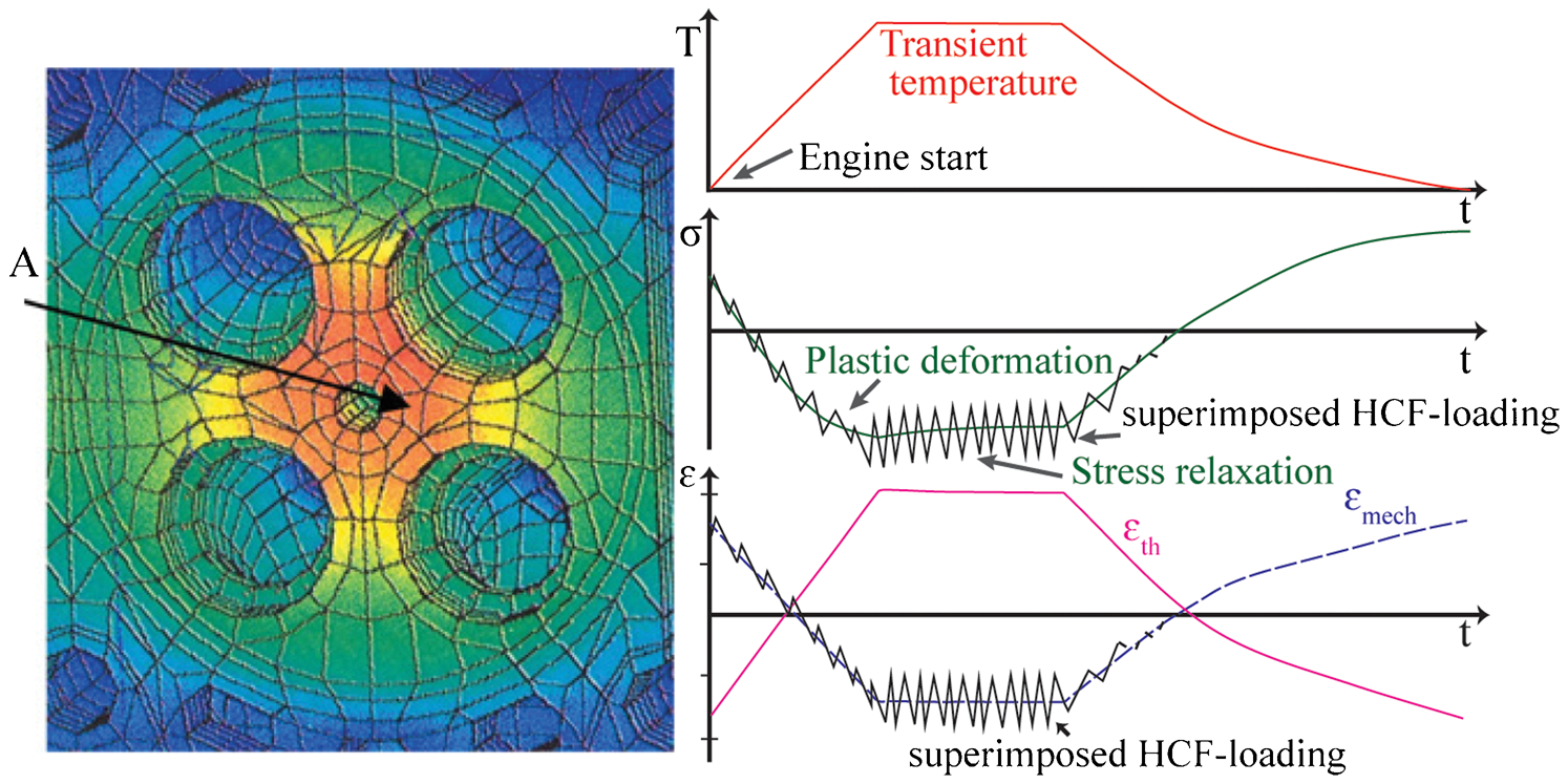
The mechanism of fatigue failure can be explained as follows. After ignition of the engine, the valve bridge is heated up and the temperature becomes quite high (exceeds 523 K) relative to the circumference of the combustion chamber. The bridge section tends to expand but cannot do so freely, since it is constrained by the water cooled flame deck across which it is suspended. This creates a local compressive stress field within the bridge section and induces compressive yielding. The most severe stress is created when the temperature difference between the combustion chamber and the water cooled flame deck is the largest (i.e. at the maximum speed). It is important to note that plastic deformation, which occurs at high temperature, does not cause fatigue cracking (because of it being in a compressive state) as long as the engine is running. 15,16,19 When the engine is turned off, the bridge section tends to contract while cooling back to room temperature. The yielded regions cannot return to the initial condition and tensile stresses are generated in these regions. 19,24,25 Therefore, the stress field for the yielding regions of the cylinder head is compressive at high temperatures, but becomes tensile at low temperatures (as shown in Fig. 5). The repetition of these compressive–tensile stress cycles is considered to cause the cracking in the radial direction. As a result, the number of engine start–stop cycles could be a better indicator of TMF failure than the mileage of a vehicle. 6,22
Therefore, to prevent crack initiation, the alloy must have either high yield strength to accommodate stress elastically, or high ductility to delay crack formation. 23,26,27 The former is required to prevent gas leakage, and the latter is required to prevent cracking in the valve bridge area of a cylinder head. Another factor that must be taken into account is the degradation of strength owing to overaging, which makes plastic deformation easier. 22,26,28 Moreover, there are some other parameters that improve TMF resistance such as: narrow thermal stress hysteresis loop, 26,29 high thermal conductivity, low thermal expansion coefficient, 30–32 microstructural stability, 26,28 small secondary dendrite arm spacing (SDAS), 23,33 low porosity level 34–36 and low content of coarse intermetallic phases. 26,37
Engine characteristics and requirements
Diesel engines have become a suitable alternative to gasoline engines over the last decade. Cars powered by diesel engines account for approximately 50% of the total market share in Europe (60% in France). Less fuel consumption, lower CO2 emissions and larger power output and torque of diesel engines are the main reasons for this progress. 38,39 The major difference between diesel and gasoline engines is their fuel combustion method, which has been elaborated by Denton. 40 Diesel engines operate at a higher compression ratio (between 14:1 and 25:1 compared to gasoline engines at between 8:1 and 12:1) because of the higher temperature and pressure of the mixture in a diesel cycle.
To increase engine efficiency and fulfil emission standard requirements (Euro legislation), the maximum operation temperature and pressure of the engine must be raised, in particular in diesel engines. For instance, the combustion pressure in truck engines was about 125 bar in 1992 and met the Euro I regulations; but it had to rise above 200 bar to fulfil the Euro V regulations (see Fig. 6). This has increased the maximum operating temperature of cylinder heads from below 443 K in earlier engines 27,41 to temperatures above 523 K in recent engines. 11,21 These operating service conditions enhance the specific power of diesel engines from ∼25 kW L−1 up to 75 kW L−1. 22,42
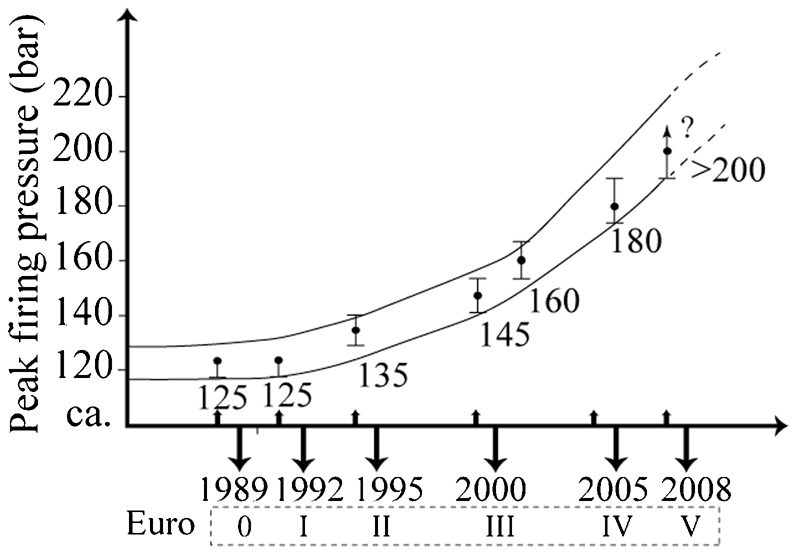
Increasing the peak firing pressure in truck engines to fulfil emissions standards requirements 43
Andersson 44 stated that only ∼12% of the total vehicle power is transferred to the wheels. About 15% of the energy is consumed by mechanical losses (mainly frictional) in powertrain system, the rest of the energy being dissipated in cooling and exhaust systems. 44,45 Funatani et al. 46 stated that friction in the engine system can lead to a loss of over 40% of total power. The major sources of these frictional losses are attributed to the contact between the piston assembly and cylinder bore. 45–47 Therefore, surface modifications of the cylinder bore could contribute to significant friction reduction, with further benefits for emissions and fuel economy. 46,48 A 10% decrease in frictional losses could reduce fuel consumption by about 3%. A volume of 600 L of petroleum could therefore be saved for each vehicle having an average fuel consumption of 10 L/100 km and running a distance of 200 000 km over its entire lifetime. 44
Engine components and requirements
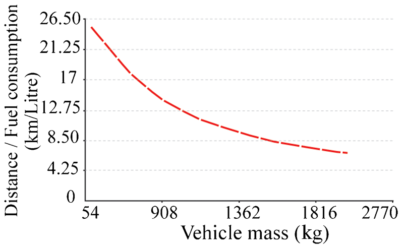
The engine block and cylinder head, which are shown in Fig. 7, are the two major components of an engine; both components have historically been manufactured from cast iron owing to its inherent high-temperature strength. Nevertheless, cast iron is a dense material (∼7·5 g cm−3) and the engine is the single heaviest component within the powertrain group (∼14% of total vehicle mass). 49 About 3–4% of the total mass of an average vehicle is generally assigned to the engine block. The improved specifications and legislations for fuel economy and emissions oblige car manufacturers to make a significant weight reduction in their products. It has been reported that each 100 kg in weight reduction could contribute to ∼0·5 L of petrol being saved per 100 km driven. 49–52 As illustrated in Fig. 8, weight reduction of a vehicle by a certain amount could result in significant improvement in fuel economy. 53,54 Social impetus, for instance the US Partnership for a New Generation of Vehicles (PNGV) programme, demands car manufacturers to produce vehicles having a fuel consumption of lower than 1 L/30 km. 55
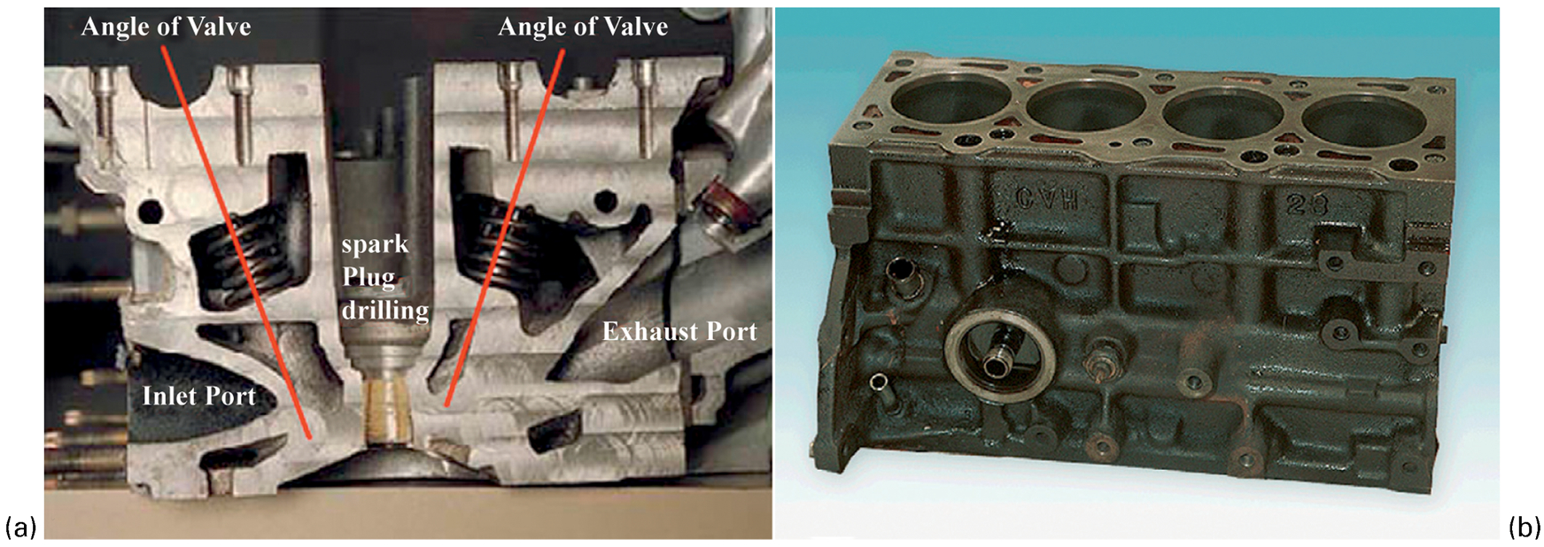
a Cross-section of a cylinder head and b engine block (reprinted with permission from Taylor & Francis) 40
Using materials with higher strength and stiffness, such as compacted graphite iron (CGI) instead of grey cast iron, contributes to increase in power and decrease in size of an engine by reducing the main bearing thickness (see Table 1). 50 Another alternative is to replace cast iron with lightweight materials (e.g. aluminium and magnesium alloys). Owing to the considerable difference in the density between cast iron (∼7·5 g cm−3), aluminium (∼2·7 g cm−3) and magnesium (∼1·74 g cm−3) alloys, the substitution of cast iron by one of these alloys could make a significant weight reduction.
Weight reduction results for CGI v. grey cast iron cylinder blocks 50
Magnesium alloys
Magnesium is ∼75% and ∼33% lighter than iron and aluminium, respectively. It has attracted great interest in the automotive industry. However, the specific stiffness of aluminium and iron has been reported to be slightly (∼0·69% and 3·752%, respectively) higher than that of Mg; but the specific strength of Mg is significantly greater than that of aluminium and iron (14·075% and 67·716% for aluminium and iron, respectively). 53,56
The regular commercial cast Mg alloys (e.g. AZ91 and AM50), which are widely used in the automotive industry, suffer from poor creep resistance. 57 The creep resistance of the magnesium alloys (e.g. AM50: Mg–5Al–0·3Mn–0·2Zn (approximate wt-%1)) has reported to be ∼15% less than that of aluminium alloys (e.g. A380: Al–8·5Si–3·5Cu–3Zn (approximate wt-%)) at 293 K, and ∼65% less at 403 K. 58 Therefore, new Mg alloys (e.g. MRI 201, MRI 230) have been developed to improve the creep resistance and high-temperature strength. These alloys could compete with the commercial Al alloys (e.g. A380 and A319) in terms of creep resistance and high-temperature strength. 59–61
Despite these advantages, application of magnesium alloys in the automotive industry has been very limited: the average application of Al alloys has been reported to be over 100 kg per car, while that of Mg alloys has been reported as ∼6 kg. 62 The higher total cost of Mg alloys is one of the major reasons for impeding their widespread application in the automotive industry. 62–64 It is worth noting that the price of magnesium has been considerably reduced in the last few years. 56 Lower thermal conductivity and higher thermal expansion are other disadvantages of Mg alloys compared with Al alloys. 57
Aluminium alloys
In the late 1970s, the generation of aluminium engine blocks was introduced to be used in gasoline engines. However, because of technical requirements, application of aluminium alloys was very limited in diesel engines until the mid-1990s. Nowadays, blocks for gasoline engines are generally cast in aluminium alloys; and the use of aluminium in diesel engines is continuing to increase. Also, most cylinder heads are cast in aluminium alloys.
Substitution of cast iron by aluminium in engine blocks could result in a weight reduction of 15–35 kg. 65 Inline cylinder blocks made in aluminium are noticeably lighter than corresponding cylinder blocks produced with CGI. For an engine weighing 35 kg in CGI, the weight of the inline cylinder block should be 28 kg using an aluminium alloy. 50 However, if the design of the engine is adapted to CGI (V-8 instead of inline), a marginal weight saving can be made with CGI.
A comparison of some important properties of Al alloys, Mg alloy, grey cast iron (GJL-250) and CGI (CGV-400) is shown in Fig. 9. As shown in this figure, another advantage of aluminium alloys compared to cast iron is their excellent thermal conductivity, which accelerates cooling of engine. In spite of all these advantages, softening of the commercial foundry aluminium alloys at service temperature restricts their application in engine components. For instance, as shown in Fig. 10, some studies from AVL reported that the application of aluminium engine blocks must be restricted for those passenger car engines with 150 bar peak firing pressure. 66,67
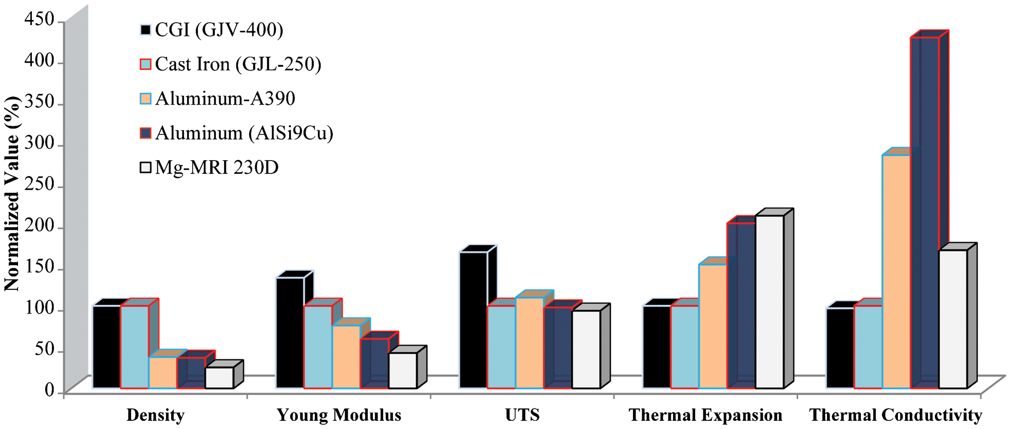
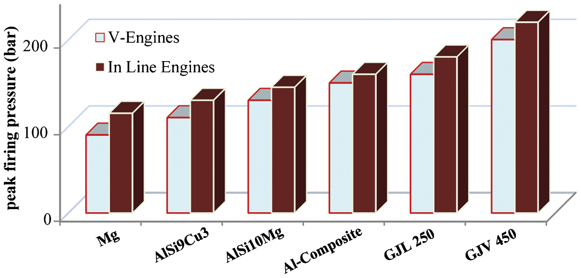
Table 2 presents the chemical compositions of the most common aluminium alloys used in engine applications. Alloys 356+Cu and 319 have been extensively studied for use in engine components, in particular in cylinder heads. For instance, they were studied by BMW, 13,68 VAW Aluminium AG, 69 Ford Motor Company 70 and General Motors. 71,72 Considering their importance, special emphasis will therefore be given to the 356- and 319-type alloys in the following sections. Hypereutectic Al–Si alloys could be another alternative for cast iron in production of engine blocks. Jorstad, 73 who is often credited as the pioneer of 390 hypereutectic Al–Si alloys, has thoroughly reviewed the application of these alloys in the manufacture of engine block from inception until now. Mercedes, BMW, Porsche, Audi and Volkswagen are some of the companies which have used hypereutectic Al–Si alloys in the production of engine blocks.
Chemical composition (wt-%) of 356-type, 319-type and 390-type Al alloys
Table 3 presents some major mechanical and physical properties of three Al–Si (319-, 356- and 390-type) alloys. The symbols F (as cast, without heat treatment), T4 (quenched and naturally aged), T5 (artificially aged after casting), T6 (quenched and artificially aged for maximal strength) and T7 (quenched and overaged), which represent the most common heat treatment condition of Al–Si alloys, have been designated by the Aluminium Association of the USA. 76
Some major properties of the Al 319-, 356-, and 390- type alloys 77
(a) These nominal properties are useful for comparing alloys, but they should not be used for design purposes. (b) Offset: 0·2%. (c) 500-kg load on l0-mm ball. (d) Endurance limits based on 500 million cycles of completely reversed stresses using rotating beam-type machine and specimen. (e) Average of tension and compression moduli. (f) Ability of alloy to withstand stresses from contraction while cooling through hot-short or brittle temperature range. (g) Ability of molten alloy to flow readily in mould and fill thin sections. (h) Decrease in volume accompanying freezing of alloy and measure of amount of compensating feed metal required in form of risers. (*) For ratings of characteristics, 1 is the best and 3 is the poorest of the alloys listed.
The 356-type aluminium alloys present good combinations of strength and ductility, but their strength reduces rapidly above 473 K (200°C). The 319-type aluminium alloys present relatively higher yield and creep strength at elevated temperatures (∼523 K), although prolonged exposure at such temperatures could result in softening. Therefore, to achieve the increasingly exacting requirements of engine components (higher pressure and temperature) without new material inventions, the existing capabilities of Al–Si hypoeutectic alloys have to be improved by optimisation of either production process (e.g. casting and heat treatment) or chemical composition.
The rest of this review is dedicated to the characteristics of Al–Si based alloys and how their composition, their processing and their final microstructure can improve their performance in engine applications. Characteristics of these alloys are first reviewed essentially when used in cylinder heads (Sections ‘Description of Al–Si based alloys’, ‘Solidification sequence in 356 and 319 Al alloys’, ‘Effect of microstructural features on TMF strength’, ‘Strengthening of cast aluminium alloys’, and ‘Recent developments in Al–Si alloys and applications in engine components’). The topics that are more specifically addressed are solidification microstructures, TMF, strengthening mechanisms, dispersed phases, heat treating and recent developments of Al–Si alloys. The major characteristics required for cylinder head materials are TMF strength, low density and high thermal conductivity. For cylinder blocks, however, besides these characteristics, appropriate friction coefficient and wear resistance are the other two major required characteristics. Hypereutectic Al–Si alloys (e.g. A390) could be an interesting alternative for cast iron engine blocks, but they suffer from cost issues and troubles in the production process (e.g. casting and honing processes). Hypoeutectic Al–Si alloy engine blocks are subject to wear; therefore, the cylinder bore of hypoeutectic Al–Si alloy cylinder blocks is required to be protected by suitable materials. Thermal spray coating, electroplating and reinforcement by suitable particles/fibres are the main solutions to fortify the cylinder bore. The requirements and potential alternative materials in manufacturing cylinder blocks are reviewed in the ‘Characteristics of the engine block’ section.
Description of Al–Si based alloys
The binary Al–Si system
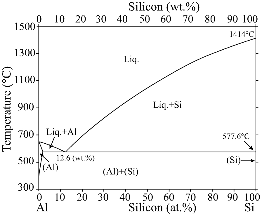
The phase diagram of the Al–Si system is illustrated in Fig. 11. There is an eutectic reaction at 850·75 K and 12·6 wt-% silicon, where the liquid phase is in equilibrium with the α-Al solid solution phase and nearly pure Si (L→α-Al+Si). 78,79 The maximum solubility of silicon in aluminium is ∼1·5 at-% at the eutectic temperature and decreases down to ∼0·05 at-% at 573 K. Generally, the morphology of the eutectic microconstituent tends to be fibrous if the volume fraction of the minor phase is less than 25%. However, in Al–Si binary alloys, the typical Al–Si eutectic morphology is usually lamellar. This could be ascribed to the low interfacial energy between Al and Si and the strong growth anisotropy of silicon. 79
The morphology of the eutectic silicon particles (i.e. particle size and shape) can appreciably affect the mechanical properties of Al–Si alloys. The coarse lamellar silicon particles, which appear under normal solidification conditions, may act as stress concentration sites and crack propagation paths. 72,80,81 This negative effect can be alleviated by imposing higher solidification rates, 82,83 carrying out solution heat treatment 26,84 or by alloying with certain elements (e.g. Sr, Na, etc.), which can change the morphology of Si particles from plate-like form to fine fibrous form. 85,86 During the solution heat treatment, the unmodified Si particles undergo: (a) necking at several places along the length of the Si particles resulting in their fragmentation, (b) gradual spheroidisation of the fragments and (c) coarsening by the Ostwald ripening process. 26,84
There are numerous elements which can modify the Al–Si eutectic microstructure, such as Sr, 85,87 Na, 88 Ca, 89,90 Sb, 91 Sc 92,93 and several rare earth metals. 94 It was proposed that the modifier agent is adsorbed at the silicon/liquid interface and results in the growth of twins and branching of silicon particles. 86,95,96 Such modifications could reduce the solution treatment time and improve the overall mechanical properties. 37,97 Nevertheless, some studies 98,99 have shown that the addition of the modifier elements is often associated with increased porosity. Gruzleski and Closset 100 and Lados et al. 101 stated that chemical modification by Sb and Sr did not have a considerable impact on fatigue lifetime of AlSiMg alloys; meanwhile Gundlach et al. 26 reported the beneficial effect of eutectic Si modification on thermal fatigue resistance. Therefore, an optimum content of the modifier agent is required to yield an acceptable level of modification without affecting the porosity level. The optimum content can be varied depending on the constituents of each alloy. For instance, the modifying effect of Sr can be somewhat nullified by the presence of other elements, namely P, Bi, Sb 102 and Mg. 72,102 For more details on the modification of Al–Si casting alloys refer to various publications. 83,102,103
Silicon significantly improves castability (fluidity, metal-feeding) 104,105 and wear resistance 106 and contributes to reduce the density and the coefficient of thermal expansion of aluminium alloys. 104 In addition, dissolution of Si in α-Al matrix (e.g. ∼0·7 wt-% at 773 K) can significantly improve the age hardenability of AlSiCuMg alloy by combining with Mg. 107
Influence of iron as impurity
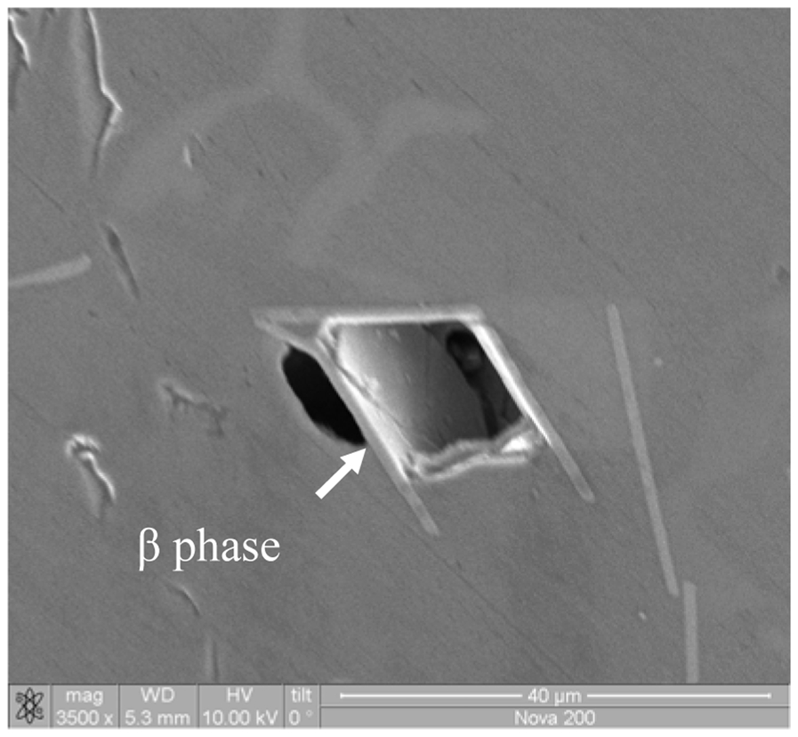
Al–Si binary alloys, even prepared from pure materials (∼99·99%), can contain more than 50 ppm of iron. The presence of iron can considerably affect the solidification process of Al–Si alloys. 78 Iron, as the most common impurity in Al–Si alloys, strongly reduces the fluidity and the overall mechanical properties through the formation of brittle intermetallic phases. Primary Al–Si alloys typically contain between 0·05 and 0·3 wt-% Fe; but, in secondary Al–Si alloys, it can reach up to 1 wt-%. Economically, there is no known way to further reduce Fe from primary Al–Si alloys. Owing to a relatively high solubility of Fe in liquid Al, it can readily enter into the melt from unprotected steel tools, furnace equipment and addition of low-purity alloying materials. 108 The amount of Fe exceeding the solid solubility limit appears in the form of iron-bearing intermetallic phases such as β-AlSiFe, α-AlSiFe and π-Al8FeMg3Si6. The α-AlSiFe phase, which appears in the form of Chinese script particles, has the composition of Al8Fe2Si (∼31·6% Fe, ∼7·8% Si). The stoichiometry of the β-Al5FeSi phase is Al5FeSi (∼25·6% Fe, ∼12·8% Si), with a probable range of 25–30% Fe and 12–15% Si. The β-Al5FeSi phase has a platelet morphology (in three dimensions), which appears as a needle in micrographs. 109,110
Many studies 108,111,112 found that as Fe levels increase, the ductility and tensile strength of Al–Si alloys strongly decrease; however, the yield strength remains in general almost unaffected by iron. The iron-bearing compounds are much more easily fractured under tensile load compared to the Al matrix or the modified silicon particles. Their detrimental effect is directly proportional to the morphology, size and volume fraction. The platelet morphology of β-phase explains why it is the most deleterious intermetallic phase in cast Al–Si alloys. 113,114
The size and density of iron-bearing compounds (particularly β-phase) increase with iron content. Moreover, intermetallic phases that can form prior to (or with) the solidification of the aluminium dendrite network (pre-dendritic particles) are much larger than those that form during or after the period of Al–Si eutectic solidification. 115 More available time for growth at a slower solidification rate also leads to enlarged intermetallic particles. 108 Furthermore, it has been reported that the amount and size of porosity in the microstructure are strongly enhanced by increasing Fe content. This behaviour is mainly related to the increased amount of β-phase, since it promotes shrinkage porosity during solidification by physically blocking the metal feeding, as shown in Fig. 12.
The role of Al5FeSi in the formation of shrinkage porosity (reprinted with permission from Taylor and France) 124
The β-platelets are much more susceptible to crack linkage and fracture than the α-iron Chinese script particles, so the formation of the α-iron phase instead of the β-phase can be less detrimental to mechanical properties owing to its compact morphology. According to Mondolfo, 109 low Mn and Cr concentration and a low cooling rate (∼0·8 K s−1) are the main factors that favour the crystallisation of β-phase. Hence, chemical modification (by Mn, Cr and Ni addition), high solidification rate 114,116–118 and superheating of the melt 119 contribute to the formation of the α-iron phase. The amount of Mn needed to convert all of the β phase is not yet well known. Several researchers 120,121 reported that an Mn/Fe ratio of 0·5 seems to be sufficient for complete substitution of Al5FeSi by α-Al15(Fe,Mn)3Si2 phase. However, other researchers 108,122 stated that even at these levels of Mn addition some β-phase could still form. It should be noted that an undesired amount of Mn in AlSiCu/Mg alloy could lead to the precipitation of Al–Cu–Mn particles (T-Al20Cu2Mn3 phase 123 ) during solution treatment, which in turn decreases the Cu content in α-Al matrix. 107 Kim et al. 116,118 reported that the combined addition of Mn and Cr to modify β-phase could be more effective which considerably improved tensile properties (ultimate tensile strength (UTS) and elongation); the improved mechanical properties were attributed to the precipitation of α-Al(Mn,Cr,Fe)Si nanoparticles in the microstructure of A356 Al alloy.
Solidification sequence in 356 and 319 Al alloys
356-type Al alloys
Backerud et al. 74 studied the solidification sequence in various Al alloys using a thermal analysis technique, followed by a subsequent metallographic examination of specimens. Their results on solidification of A356·2 alloy with a cooling rate of 0·7 K s−1 are summarized in Table 4. Reactions (2b) and (3b) were not observed by Arnberg et al. 125 and Mackay et al. 126 in their investigation of almost the same chemical composition. They stated that no pre-eutectic (Al5FeSi) phase could be crystallized with such low Fe contents, although their specimens contained 0·08% Fe as did those of Backerud et al. 74 Backerud et al. 74 stated that the Fe is strongly partitioned in the liquid phase which results in precipitation of the pre- or co-eutectic Al5FeSi phase. Subsequently, the Al5FeSi phase is partly transformed into the Al8FeMg3Si6 phase through a quasi-peritectic reaction (3b). Wang et al. 127 confirmed the Backerud et al. 74 results on solidification sequence by scanning electron microscopy (SEM) analysis. As illustrated in Fig. 13, the π-Al8FeMg3Si6 phase was directly grown from the Al5FeSi phase, which could imply the occurrence of reactions (3a) and (3b).
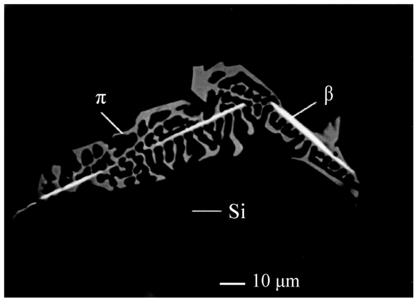
SEM micrograph of A356 as-cast Al alloy showing the close association between Al5FeSi and π-Al8FeMg3Si6 phase (reprinted with permission from Springer) 127
Reactions occurred during solidification of A356·2 74
319-type Al alloys
The solidification sequences of two 319-type aluminium alloys with chemical compositions of (Al–5·7Si–3·4Cu–0·62Fe–0·36Mn–0·10Mg (wt-%)) 74 and (Al–6·23Si–3·8Cu–0·46Fe–0·14Mn–0·06Mg (wt-%)) 121 are listed in Table 5. The precipitation of Al15Mn3Si2 (possibly together with Al5FeSi) which was observed by Backerud et al. 74 was not detected by Samuel et al. 121 This is presumably because of the smaller Mn content of the alloy studied by the latter authors. The presence of Mg (even in the small amount of ∼0·06 wt-%) leads to the transformation of the Al5FeSi phase to π-Al8FeMg3Si6 phase as well as precipitation of Mg2Si phase during solidification, attributed to reaction (C) in Table 5. 121,128 Furthermore, precipitation of Q-Al5Cu2Mg8Si6 phase, corresponding to reaction (E), is caused by the addition of Mg. 121,129 The Q-Al5Cu2Mg8Si6 phase grows out of θ-Al2Cu particles during the complex eutectic reaction in the final stages of solidification. 72,130 The morphology of the θ-Al2Cu phase, which can be of blocky or eutectic form, strongly depends on solidification rate and Sr modification. It has been reported that high solidification rate leads to fine eutectic Al–Al2Cu phases, 121,131 while Sr modification increases the proportion of blocky Al2Cu phase. 132–134
Summary of reactions occurring during solidification of 319·1Al alloys
Effect of microstructural features on TMF strength
It is largely accepted that fatigue lifetime of Al–Si based alloys (319- and 356-type Al alloys) is more affected by the actual casting processes than by alloy chemistry. Crack initiation can be greatly delayed in defect-limited specimens. 12,23,135 Porosity and oxide inclusions are the most deleterious metallurgical defects associated with casting processes and both strongly impair the fatigue strength. There is a critical size of the pores and inclusions below which the impact of these defects is not the root cause of fracture, and cracks can be initiated by other microstructural features like large eutectic constituents (fractured/detached Si particles) or persistent slip bands. 68,136–138
The transition from one mode of failure to another is of importance in predicting the service lifetime of engineering components. For instance, transition from transgranular to intergranular fracture is usually followed by a dramatic reduction in ductility and fatigue lifetime. Creep damage, which is in the form of intergranular cracking, is generally observed in in-phase TMF test specimens. No detectable intergranular damage in isothermal and out-of-phase TMF tests was reported by a majority of researchers. 70,139,140 Therefore, to develop a new alloy, the creep/fatigue failure mechanisms have to be clarified in terms of intrinsic material properties and microstructure.
Porosity
The combined effect of volumetric shrinkage and dissolved gas leads to the formation of porosity. 111,141 In alloys with low fluidity, the shrinkage of the melt between dendrites cannot be fully filled by the liquid phase remaining, which leads to porosity being spread out along these dendrites. The only gas which is sufficiently soluble in aluminium alloys and leading to porosity is hydrogen. 142,143 The solubility of hydrogen decreases with decreasing temperature and hydrogen atoms precipitate and form molecular hydrogen during solidification.
Porosity formation in Al–Si hypoeutectic alloys can be affected by alloying elements via a few mechanisms. Addition of Cu to Al–Si alloys assists porosity formation by increasing both the solidification range and the solidification shrinkage. 144–146 The overall solidification shrinkage in Al–Cu binary alloys is ∼8·4% while it is ∼4·5% for Al–7% Si. 145–147 Moreover, increasing the copper content enhances the activity coefficient of hydrogen which, in turn, decreases the solubility of hydrogen. Therefore, the alloys containing copper can be more prone to form porosity during solidification. 148 Caceres et al. 144,146 stated that ‘the addition of only 1% Cu causes the development of a significant level of porosity in comparison with the Cu-free A356·2 alloy, while increasing the levels of Cu beyond 1% and up to about 4% results in a relatively small increase in porosity level’. The iron-bearing platelets (e.g. β-AlSiFe phase) reduce permeability and restrict the flow of liquid metal at the latter stage of the solidification process, 149 which was elaborated in the ‘Influence of iron as impurity’ section. Grain refinement obtained by alloying elements such as titanium and boron reduces the volume fraction and size of porosity. 149,150 It is worth pointing out that Mg 146,149 and Si 145,146 can have a positive impact in reducing both pore size and density.
Tensile and fatigue properties are made significantly poorer by increasing porosity. 36,42,151 Surappa et al. 152 found that the decrease in the elongation to fracture could be correlated to the pores on the fracture surface. Ma 153 showed that increasing metal soundness, in terms of porosity, resulted in a higher elongation to fracture in alloys A319 and A356. The effect of porosity on fatigue strength is strongly dependent on a number of factors, such as morphology, size and position of the pores within the cast part. Skallerud et al. 154 reported that a shrinkage pore could be more deleterious than a gas pore. Fatigue cracks are generally initiated from shrinkage pores at or near the free surface of a specimen. The effect of large pores far away from the free surface of specimens on the fatigue lifetime can be very small, while even a small pore (or inclusion) located near the free surface can be very deleterious to fatigue lifetime. 36,155,156
Secondary dendrite arm spacing
In an alloy microstructure, the SDAS generally characterises the solidification rate. Increasing the solidification rate substantially improves the fatigue and tensile properties (except modulus). 34 This improvement is generally attributed to the influence of solidification rate on the number density and size of porosity, and to the refinement of grains and secondary phase microconstituents. 23,157 Several authors 12,23,135 reported that reducing SDAS strongly decreased both the number density and the average pore size in Al–Si alloy castings. Chen et al. stated that ‘in A356·2 Al alloy as the SDAS increases from 15 μm to 50 μm, the fatigue lifetime decreases about three times under LCF and over six times under HCF’, since for the alloy with SDAS greater than ∼30 μm, pores act as fatigue crack initiation sites. 158,159 Furthermore, the content of β-Al5FeSi as the least desirable secondary phase was significantly reduced by the increasing cooling rate (see Fig. 14). 23 So, one can say that the influence of SDAS cannot be separated from the influence that solidification rate has on the size and distribution of all microconstituents.
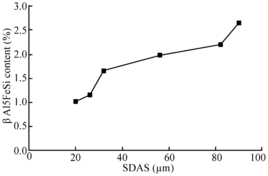
Effect of cooling rate on the formation of β-Al5FeSi brittle phase 23
Segregation
Segregation is another important phenomenon which can considerably affect fatigue lifetime. In casting, heat is transferred through the mould walls and this causes higher volume fraction of the α-Al phase to be located in the outer surface of the casting and a larger volume fraction of eutectic phases and shrinkage porosity to be located in the centre. Consequently, local fatigue resistance could vary with the location within a casting. Seniw et al. 155,160 reported interesting results on the effect of segregation of Si on fatigue properties of A356 cast alloy. They revealed that specimens taken from the outer surface of a cast bar, which was the first zone to be solidified, survived 106 cycles without failure, while specimens taken from the part to solidify last failed after only 150 000 cycles. This illustrates how fatigue lifetime can be reduced down the solidification path.
Cracking/debonding of Si particles
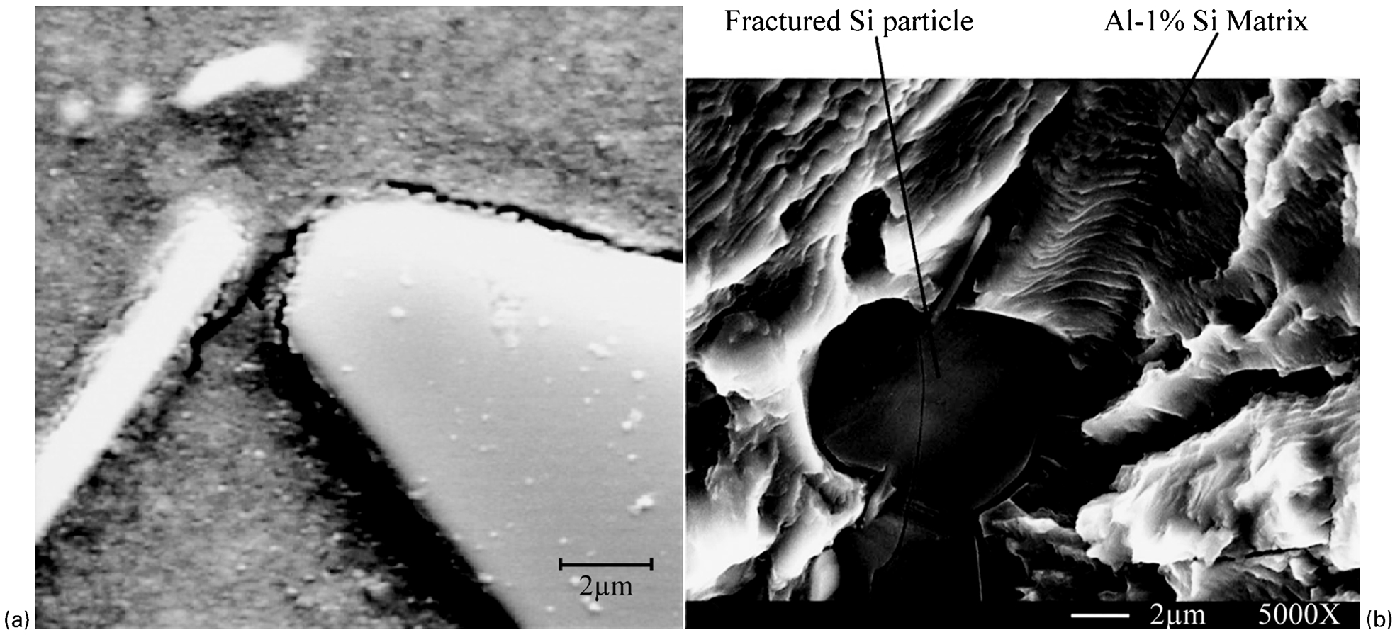
Crack propagation in Al–Si based alloys depends on the size, orientation and local distribution of the Si particles. 101,161,162 In modified Al–Si alloys (fine Si particles, size ∼1·5–2·5 μm), fatigue cracking progresses by decohesion of the Si particles from the Al matrix. But, with increasing Si particle size, the tendency to particle cracking increases, such that in unmodified alloys (coarse Si particles, ∼3–9 μm) particle cleavage is the dominant feature. 101,163,164 Figure 15 illustrates the debonding of a Si particle from the Al matrix and a fractured Si particle caused during a fatigue test. Plastic deformation in TMF loading can cause debonding of Si particles. 68,81,165 This is a result of significant thermal/mechanical misfit between the brittle Si particles and the surrounding ductile matrix, which leads to separation during thermal/mechanical loading. 68,137
Slip bands
Several researchers 166–169 reported that in the absence of casting defects (e.g. porosity) or in castings with small SDAS, 170 cracks initiated from persistent slip bands on the surface. Nyahumwa et al. 168 observed a faceted transgranular appearance on the fatigue fracture surface of hot isostatic pressed A356·2 aluminium alloy. They reported that the faceted transgranular fracture mode of some specimens was by the slip mechanism. Jiang and co-workers 171 observed slip band cracking only in naturally aged and underaged samples. Zhu et al. 167 also reported that twin boundary initiated failures in 319 Al alloy could occur only at elevated temperature. Jang et al. 166 hypothesised that, with increasing temperature, the critical effective stress for fatigue crack initiation (CESFCI) value at slip band would be comparable to the CESFCI value at porosity, while it is lower at porosity than at slip band at room temperature. Moreover, Jang et al. 166 reported interesting results on TMF crack initiation in cast 319-T7 aluminium alloy. The crack initiation of 11 specimens (out of 29 specimens) occurred at near surface porosity, but, for those specimens with relatively small porosity near the surface, coarse transgranular facets were observed at the crack initiation site. They proposed that the slip band mechanism was responsible for crack initiation. Owing to the presence of oxide films in these transgranular facet areas, the authors 166,172 concluded that these oxide films were formed as a result of fretting damage under fatigue cyclic loading, rather than pre-existing oxide films. However, Campbell 173,174 criticised their idea and proposed that the oxide film on the fatigue initiation site was created as an inclusion during the solidification, and was a prerequisite for slip band crack initiation.
Gundlach et al. 26 investigated TMF of 319 and 356 Al alloys and reported the occurrence of stress relaxation in 356 Al alloy on heating above ∼505 K. Takahashi et al. 29 stated that stress relaxation started at ∼493 K in the TMF process of Al–6Si–2·5Cu–0·3Mg (wt-%) alloy. At this temperature, which is ∼0·56T m,2 diffusion creep and dislocation creep can occur; 169 therefore, they concluded that these creep micro-mechanisms could be responsible for softening of the alloys. 29 Angeloni 175 also reported that the aforementioned creep micro-mechanisms could be responsible for plastic deformation of Al–9Si–3Cu–0·3Mg (wt-%) alloy in elevated temperature fatigue tests (∼553 K).
Strengthening of cast aluminium alloys
The principal objective in the design of aluminium alloys is to improve their tensile strength, hardness, creep resistance and fatigue resistance. The strengthening of cast aluminium alloys relies on several different mechanisms based on restricting/hindering the motion of dislocations. The two major methods used to strengthen cast Al alloys are precipitation hardening and dispersoid hardening; the latter refers to precipitates formed with transition elements and stable at higher temperatures. The works dedicated to applying and optimising these methods will be described in this section.
Heat treatment of AlSiCuMg alloys
The common thermal treatments, which are generally applied for AlSiCuMg cast alloys, involve either age hardening of the as cast alloy (T5 type) or solution treatment followed by age hardening (T6, T7 type). 104,176 If peak mechanical properties are not required, castings with sufficiently high cooling rates and artificially aged (T5 type) may meet the intended strength requirements. This allows a reduction of production costs since the solution heat treatment is not made. However, T6 (‘peak-aged’) and T7 (‘overaged’) are the most common heat treatments made on AlSiCuMg alloys. The T6 heat treatment is generally used for room temperature applications, 177,178 while for high temperature applications, and especially in the case of 319-type Al alloys, the T7 treatment is recommended. 22,28,179 These heat treatment processes, which involve the following three consecutive stages, have to be optimised: (1) solution treatment, (2) quenching and (3) ageing. 180–182
Solution treatment
The solution heat treatment is achieved by heating the alloy at a temperature range between the solvus and the solidus line (see Fig. 16). The soaking period must be long enough to cause one or more constituents to enter into solid solution. Homogenisation of the alloying elements and spheroidisation of the eutectic Si particles are the other purposes of the solution treatment. 183,184
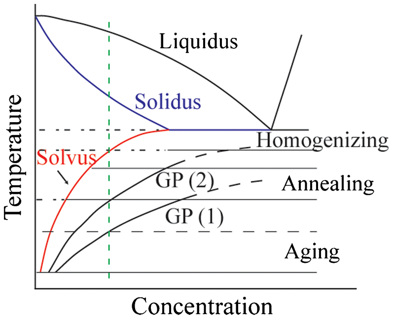
Temperature ranges for heat treatment and relevant solvus line for binary aluminium alloys 184
The dissolution rate of intermetallic compounds is strongly dependent on the solutionising temperature. Samuel 185 has reported that increasing the solutionising temperature from 753 to 773 K in Al–6·17Si–3·65Cu–0·45Mg (wt-%) alloy improved the yield strength from 330 to 410 MPa and the UTS from 340 to 420 MPa. On the other hand, the maximum applicable solution treatment temperature is limited by incipient melting of the last solidified phases. 185–187 Incipient melting deteriorates the mechanical properties as a result of void formation. 131,180 According to Samuel, 185 the solutionising temperature of a cast Al–6Si–3Cu (wt-%) alloy containing 0·04% Mg can be ∼792 K, but increasing the Mg content to 0·5% restricts the solution treatment temperature to ∼778 K to avoid incipient melting. 185 It has been reported that even a small amount of Mg (0·1 wt-%) can reduce the solidus temperature of a 319·0-type Al alloy down to 780 K under non-equilibrium solidification conditions. 74,121 Moreover, Fuoco et al. 188 pointed out that the solutionising temperature for AlSiCuMg alloys must not exceed 773 K to avoid incipient melting. Therefore, the melting point of the last solidified phase must be known accurately to optimise the solutionising temperature. This can be achieved by using a microsegregation model or by conducting a thermal analysis.
Sokolowski et al. 189,190 reported that single-step solution treatment of Al–7Si–3·7Cu–0·23Mg (wt-%) alloy, which must be at less than 768 K, is neither able to maximise the dissolution of Cu rich phases nor able to homogenise the microstructure and modify the Si particles. As a result, they proposed a two-step solution treatment (i.e. 8 h at 768 K+2 h at 793 K). By doing so, the Cu-containing phase (Q-Al5Cu2Mg8Si6) with the lowest melting point (∼780 K) 185,191 would be dissolved at the first step. The higher solutionising temperature of the second step could dissolve the remaining Cu-bearing phase and further homogenise the microstructure. 190,191 Nevertheless, some authors reported the stability or very slow dissolution rate of Q-Al5Cu2Mg8Si6 phase at ∼773 K (500°C) 192,193 when the magnesium content is sufficiently high. The holding time period of the first step and the solution temperature of the second step are very critical parameters to avoid incipient melting. 180,194,195 Therefore, to achieve an effective dissolution while avoiding coarsening of the constituents, the solutionising parameters (namely time and temperature) have to be optimised. 196,197 In this regard, differential scanning calorimetry (DSC) and electron probe microanalysis are powerful tools, which are discussed in more details below.
Wang et al. 191 used DSC analysis to optimise the solutionising treatment of Al–11Si–4Cu–0·3Mg (wt-%) alloy. Figure 17 displays the DSC curves of the alloy for different solution times at 773 K. Peaks (1), (2) and (3) correspond to the following reactions:
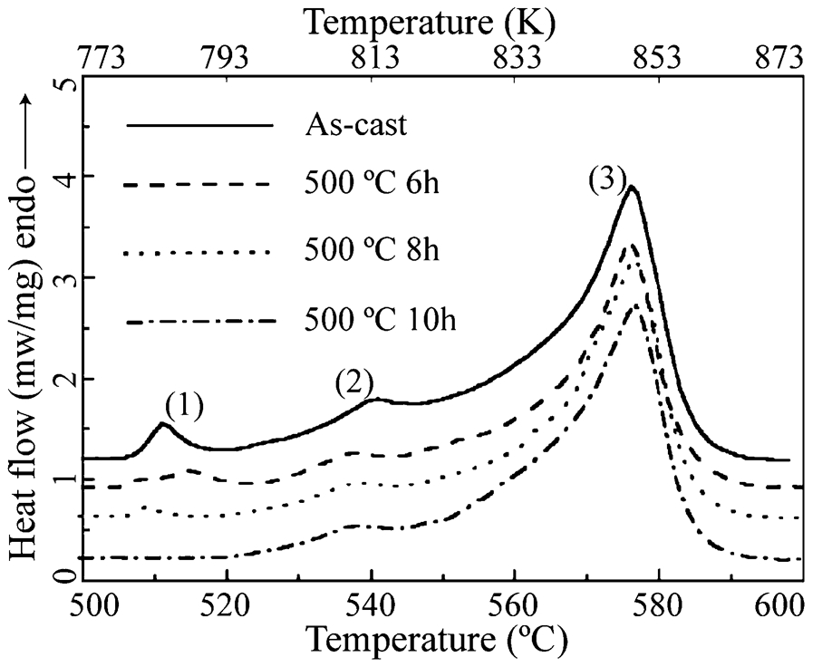
DSC curves of AlSiCuMg alloy solution treated at 773 K for different times (reprinted with permission from Elsevier) 191
Reaction of peak (1): α (Al)+Al2Cu+Si+Al5Cu2Mg8Si6→Liquid
Reaction of peak (2): α (Al)+Al2Cu+Si→Liquid
Reaction of peak (3): α (Al)+Si (+Al5FeSi+…)→Liquid
As illustrated in this figure, with increasing solution time, the height of peaks (1) and (2) gradually decreased. After 10 hours of solution treatment, peak (1) completely disappeared, which indicates the complete dissolution of eutectic phases (α-Al+Al2Cu+Si+Al5Cu2Mg8Si6). Therefore, the temperature at the second step of solution treatment could be increased up to the onset temperature of peak (2) (∼793 K) to quickly dissolve the remaining Cu-rich intermetallics. The temperature of the second solution treatment step should be lower than 793 K in order to avoid incipient melting of (α-Al+Al2Cu+Si) eutectic phase. 191 It is noteworthy that increasing the Mg content enhances the stability of Q-Al5Cu2Mg8Si6 phase in AlSiCuMg alloy system. 193,198 For instance, Lasa et al. 193 reported that the Q-Al5Cu2Mg8Si6 phase in Al–12·5Si–4·5Cu–1·3Mg (wt-%) alloy was almost completely undissolved after 24 hours of solution treatment at 773 K.
Dissolution of Cu phases (e.g. Al2Cu/Al5Cu2Mg8Si6) which increases the Cu content in the α-Al matrix is one of the major purposes of the solution treatment. In order to determine the efficiency of a specific solution treatment, Sjolander et al. 183 and Han et al. 192,199 proposed to measure the Cu distribution in the α-Al matrix by means of line scans in electron probe microanalysis. For instance, the solutionising time of Al–8Si–3Cu (wt-%) alloy with different SDAS (10, 25, 50 μm) was studied by Sjolander et al. 183 Figure 18 illustrates the concentration of Cu in the dendrite arms for various specimens with different solution time (0, 10, 60, 180, 360, 600 min). Homogenisation in the dendrite arms occurred very fast (within 10 and 60 min), but the concentration of Cu was strongly dependent on the microstructure and solutionising time. For the finest microstructure (SDAS of 10 μm), 10 min of solutionising time seemed to be enough; but for the very coarse microstructure (SDAS of 50 μm), even 10 h of solutionising time at 768 K was not sufficient. 183
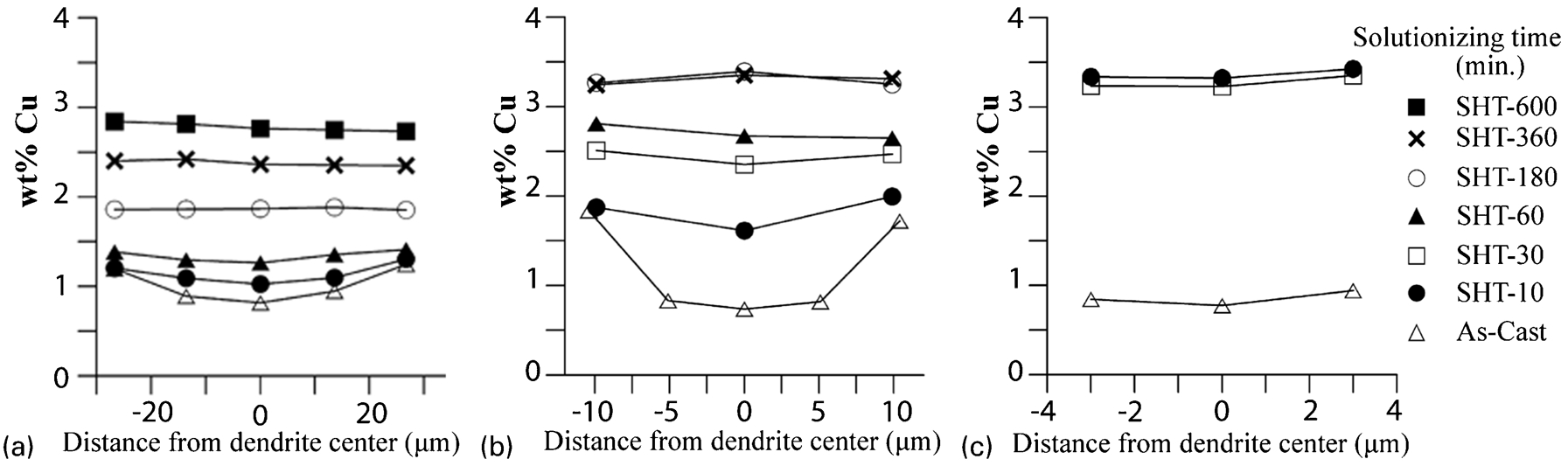
a SDAS 50 μm, b SDAS 25 μm and c SDAS 10 μm (reprinted with permission from Elsevier) 183
Quenching
The purpose of quenching is to maintain the solid solution by cooling rapidly to a low temperature in order to prevent the diffusion of the elements. As a result, solute atoms, as well as a significant fraction of thermal vacancies, are effectively frozen inside the material. This causes the concentration of solute atoms to be greater than the equilibrium level and a thermodynamically unstable supersaturated solid solution is created. 187,200,201
In order to avoid premature precipitation, which could severely deteriorate the mechanical properties, cooling rate should be fast enough. For aluminium alloys, the usual quenching media are both cold (below 303 K) and hot water (between 338 and 373 K). During quenching by cold water, the water temperature should not be increased by more than 10 K. Furthermore, the transfer time period of specimens from the furnace to the quench media must be short so as to pass quickly enough through the critical temperature range where very rapid precipitation can occur. 201–203 However, it should be taken into account that very fast quenching might cause distortion and residual thermal stresses. 203
Ageing
During ageing of Al alloys, solid solution strengthening gradually disappears and the coherent structure of Guinier–Preston (GP) zones leads to an intense strain field in the surrounding area. 204,205 The mechanisms contributing to increase the yield strength by the motion of dislocations through precipitates may include chemical, stacking fault, modulus, coherency and order strengthening. 206,207 These mechanisms were thoroughly reviewed by Ardell. 208 Ageing is performed by holding the supersaturated solid solution at temperatures below the solvus line to form a fine distribution of precipitates from a supersaturated solid solution (see Fig. 16). The thermodynamically unstable supersaturated solid solution will reach equilibrium conditions by ageing at room temperature (natural ageing) or with a precipitation heat treatment (artificial ageing). Time and temperature are the two main parameters of ageing which affect the strengthening mechanisms. Higher ageing temperature accelerates the ageing process by increasing nucleation and growth rates. 180,207,209
Several investigations have been carried out to understand the effect of underaging, peak ageing and overaging on: hardness, 210–212 tensile strength, 180,201,211 crack propagation behaviour, 171,213 TMF behaviour 214 and cyclic stress–strain response of AlSi(Cu,Mg) alloys. 215 The sequence of precipitation of θ-Al2Cu begins by GP zones, which are thermodynamically the least stable but kinetically the most favoured phases: α-Al→GP zones (plate-like)→θ″ (plate-like)→θ′ (plate-like)→θ (Al2Cu). GP zones and θ″ are fully coherent with the α-Al matrix, θ′ particles can be either coherent or semi-coherent, while θ particles are incoherent. 216–218 GP zones with 3–5 nm diameters consisting of localised concentrations of Cu atoms have been observed in specimens aged at 373 K for 2·5 h. 219 The required ageing time at 373 K was reported to be at least 1000 h to obtain a microstructure where plate-shaped Cu-rich particles (GP zones) predominate. 179,219 However, some authors have stated that GP zones undergo dissolution at temperatures higher than 373 K; 77,187 the presence of GP zones after ageing at 403 K for 16 h 220 and the coexistence of ‘GP zones and θ″’ after ageing at 423 K for 3·5 h 219 have also been reported. The peak strength is influenced by the amount, size and site density of θ″ and θ′ phases. 205 According to reports, 179,219 the reason for softening with overaging in 319-type Al alloys can be attributed to the coarsening of the θ′ phase. The transformation of θ′ to θ occurs only when ageing at 523 K (or higher) and for time periods greater than 1000 h. 179,219
Two different combinations of precipitates have been observed in peak-aged condition of the AlSiCuMg alloy system: (1) precipitation of β″ (based on Mg2Si) and/or θ′ and (2) precipitation of Q″ and/or θ′, where the θ′ phase only appears for a high concentration of Cu (≧1 wt-%). 187,221,222 In several studies, 221,222 no θ-Al2Cu phase has been reported during artificial ageing of AlSiCuMg alloys when the Cu content was less than 1·0 wt-%. Figure 19 illustrates the DSC curves of as quenched and aged Al–7Si–3Cu–0·4Mg (wt-%) alloy with a 10 K min−1 heating rate. Formation and dissolution temperature of GP zones, Q′ phase, θ′ phase and θ phase were found to be at about 303–493, 493–543, 543–633 and 633–733 K. 107 It is worth mentioning that the temperature at which a given peak occurs increases with increasing scan rate. 107,223 An exothermic peak corresponding to GP zone formation was only detected for the as quenched specimen. In the alloy with some impurities (e.g. 0·6 wt-% Fe and 0·5 wt-% Mn), GP zones could not be detected at all; instead, the precipitation of θ′ phase appeared at earlier stages. 107
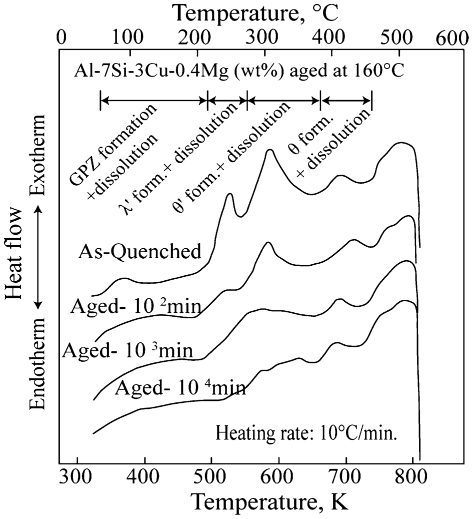
DSC curve of Al7Si3Cu0·4Mg alloy, solution-treated 10 h@773 K, water-quenched and aged for different times at 443 K (reprinted with permission from American Foundry Society) 107
The ageing time to reach peak strength is longer for AlSiCu alloy than for AlSiCu(Mg) alloy. 107 The required time period to obtain peak strength in AlSiCu(Mg) alloy varies from 30 h up to 120 h and even longer at a lower temperature (433 K). 107,224,225 The addition of Mg accelerates and intensifies the precipitation-hardening process of AlSiCu alloys. 107,209,224 Kang and co-workers 107 reported that not only was the peak hardness obtained for AlSiCu alloy lower than that obtained for AlSiCuMg alloy, but also the ageing time required to reach peak hardness for the former was ten times longer than for the latter. On the other hand, Wang et al. 221 stated that Cu addition to AlSiMg alloy not only increases the age hardenability, but also extends the time (from about 700 to 3000 min) required to reach the peak hardness.
The large discrepancy between the thermal expansion coefficients of α-Al matrix (23·5×10−6 K−1) and Si particles (9·6×10−6 K−1) generates a lot of dislocations during quenching around the Si particles and makes these locations become a preferential site of nucleation for the θ′ phase. 107,182,217 On the contrary, the Q′ phase can nucleate at locations of lower surface energy since this phase is assumed to have a better coherency (semi-coherency) with α-Al. Therefore, Q′ can precipitate on a dislocation located anywhere in the matrix giving a more homogeneous distribution of these precipitates. The lengths of diffusion are reduced and then less time is required to reach peak hardness. 107,226 This could explain the higher age hardening rate of AlSiCuMg alloy relative to AlSiCu alloy. Nevertheless, it has been reported that at elevated temperature the Cu-containing θ″–θ′ phase can be much more stable than the Mg-containing λ′–λ (Al5Cu2Mg8Si6) and β″–β′ (Mg2Si) phases. 107,227 ; also, S′–S (Al2CuMg) phase has been reported to be more stable than β″–β′ (Mg2Si) phase. 228
In addition to the presence of β-Mg2Si and Q-Al5Cu2Mg8Si6 phases in an aluminium 319 alloy, S-(Al2CuMg) phase was also identified by Medrano et al. 182 The authors stated that β-Mg2Si and S-(Al2CuMg) phases probably precipitated during solidification, and still remained undissolved after solution treatment. According to Mondolfo, 109 in AlCuMg alloy with the ratio of Cu to Mg between 4:1 and 8:1, the ageing agent would be both the Al2Cu phase and Al2CuMg phase. In the case of AlSiCuMg alloy with high silicon content, the S-(Al2CuMg) phase is not usually found, but it can be seen in small amounts owing to compositional heterogeneities. 193 Nevertheless, the presence of S-(Al2CuMg) phase in AlSiCuMg alloys has been observed by some authors. 182,209,219 Ma et al. 178 pointed out the presence of Al2Cu and Al2CuMg phase in Al–11Si–2·5Cu–0·4Mg (wt-%) alloy. Reif et al. 225,229 likewise reported the presence of S′-(Al2CuMg) phase with increasing Mg addition to AlSiCu alloy.
It is worth noting that increasing the Mg level beyond 0·3 wt-% in 319-type Al alloys does not significantly change the alloy strength, 230,231 but it can considerably reduce the ductility of the alloys. In 356-type Al alloys, increasing the Mg content up to 0·5 wt-% enhances the strength, while further increasing Mg content can have a negative effect on the strength of the alloys. 187 Wang et al. 136 reported that the fatigue lifetime of A357 alloy (with 0·7 wt-% Mg) was lower than that of A356 (with 0·4 wt-% Mg). In alloys with high Mg content, a large fraction of the π-Al8FeMg3Si6 phase could be formed which is stable during the solution treatment. 187,231
The small precipitates/zones which are cut by the dislocations in motion lead to a maximum yield stress once the dislocations pass through them. This causes the local work hardening to be small and the plastic deformation to be restricted on a few active slip planes, which would probably be very deleterious to fatigue lifetime. 220 On the other hand, for large particle size/interspacing, bypassing particles by dislocations results in rapid work hardening and the plastic strains are distributed throughout the specimen. However, because of weak strengthening of these precipitates, the yield stress is not high enough. Fine 220 stated that ‘the interesting possibility is to have a dispersion of two kinds of second phase particles, small closely spaced particles to give high yield stress plus large particles to distribute the plastic deformation throughout the material’.
Therefore regarding the operating condition, the aluminium alloys might be used after peak strengthening with metastable microstructure (T6) or after overaging with equilibrium microstructure (T7). For engine components which are exposed to TMF, T7 condition seems to be more appropriate than T6, since:
T6 condition can cause localised deformation; 220
prolonged exposure at service temperature leads to higher thermal growth3 in T6 condition. The thermal growth of W319 Al alloy was 0·045% and 0·006%, respectively, in T6 and T7 conditions; 179 and
T7 shows more stable microstructure and higher TMF lifetime than T6. 28
Dispersion hardening
Trying to improve the elevated temperature strengths of aluminium alloys has involved continuing efforts for more than three decades. 28,220 Before going further, it could be worthwhile to consider the reason for successfully engineered Ni-based superalloys being mechanically stable at high temperatures (exceeding 0·75T m). 232 The interesting mechanical properties of Ni-based superalloys at elevated temperatures can be mainly related to the presence of very large volume fractions of fine γ′-Ni3(Al,Ti) precipitate with L12 structure, which is coherent–coplanar and moderately ductile. 65,220,233 The term ‘coherent–coplanar’ means the precipitate/matrix interfacial energy is very low and the tendency for coarsening/coalescence of the precipitate is very small. To develop an effective high-strength high-temperature Al alloy, it can be useful to remember the characteristics of this precipitate in Ni superalloys. 234
Softening of the precipitation hardened Al alloys (e.g. AlSiCu) is the major problem at elevated temperatures because of the dissolution/coarsening of the metastable precipitates. A high-strength high-temperature Al based alloy must have a distribution of fine precipitates/dispersed phases, which must be thermodynamically stable, coherent–coplanar and ductile. 22,105,220 A low solid solubility as well as limited diffusivity of the solutes in α-Al at the intended service temperature, which is essential to retard volume diffusion, controls the rate of dissolution and coarsening of the precipitated phases. 220,234,235 Moreover, the larger the interfacial energy, the higher the driving force for coarsening/coalescence of the precipitates (Ostwald ripening). Therefore, the required driving force for coarsening can be very small in the coherent–coplanar precipitates. 217 Zedalis 236 stated that the coarsening rate of the tetragonal Al3Zr dispersed phase (D023 with semi-coherent interface) is 16 times higher than that of the cubic modified one (L12 with coherent interface). Furthermore, the coherency of the precipitate/matrix interface magnifies the strengthening efficiency of the dispersed phase. Accordingly, precipitated phases with a similar crystal structure and a low lattice parameter mismatch with the α-Al solid solution are preferred. 220,234,236
Among the transition elements, only the first element of the third group (i.e. Sc) exhibits a high symmetry L12 trialuminide (Al3Sc) structure which is an ordered fcc lattice of the Cu3Au type of structure. 234,237 Group 4 (Ti, Zr, Hf) and group 5 (V, Nb, Ta) elements crystallise with the body-centred tetragonal D022 and D023 (Al3M) structures, as shown graphically in Fig. 20. The brittle low symmetry tetragonal structure (of Al3M; M = Ti, Zr, Hf, V, Nb) can be transformed to the cubic structure (L12) by alloying. 234 Furthermore, it has been stated 238–241 that the precipitation sequence in the ageing treatment of supersaturated Al–Ti, Al–Zr and Al–Hf solid solutions occurs initially by the formation of a metastable cubic L12 (Al3M) phase. The overall sequence of precipitation in Al–Zr and Al–V systems has been reported 242 to be: (supersaturated solid solution)→(cubic spheres and rod L12)→(tetragonal plates D023/D022). Long term exposure (hundreds of hours) at high enough temperatures (>450°C) is required to transform these metastable phases to the equilibrium tetragonal (Al3M) structure. In other words, these phases are thermodynamically metastable (Gibbs free energies of formation of the tetragonal (D023) and cubic phase (L12) of Al3Zr are −40·75 and −38·35 kJ mol−1, respectively 243 ), but kinetically stable at elevated temperatures even close to 673 K, because of the extremely slow diffusion rate of these transition elements in α-Al. Moreover, some alloying elements can reduce much more the rate of this transformation. Zedalis 236 stated that ‘addition of V to Al–Zr alloy led to a reduction of the precipitate-matrix mismatch for both phases, and also retarded both coarsening as well as the cubic to tetragonal transformation’. Litynska 244 wrote that the addition of 0·2% Zr to Al–1Mg–0·6Si–1Cu–0·4Sc (wt-%) retarded the coarsening of Al3Sc phase and restricted the size of Al3(Sc,Zr) precipitates to about 20–40 nm, which were fully coherent with the matrix. The retardation of coarsening of Al3V phase by Zr addition was also confirmed by Fine et al. 242
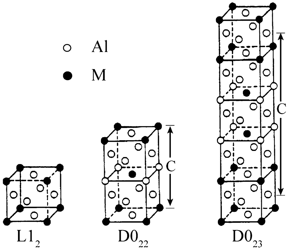
a L12, b D022, and c D023 crystal structures (reprinted with permission from Elsevier) 246
To have a coherent/coplanar interface, dispersoid phases with small lattice parameter mismatch are preferred. For the transition elements Hf, Zr, Sc, Nb, Ti, V and Ta the lattice parameter mismatches between the precipitate (pure binary Al3M (L12) trialuminides) and α-Al matrix at room temperature are 0·04%, 0·75%, 1·32%, 1·49%, 2·04%, 4·44% and 5·26%, respectively. 234,245
Because of the low volume fraction of the dispersoid phases in Al alloys, the precipitates should be very small and resistant to coarsening. Therefore, for an alloy subjected to prolonged exposure at elevated temperatures, slow diffusion kinetics is required to maintain strength. Figure 21 compares the calculated diffusivities of different solute elements in α-Al at three different temperatures (i.e. 573, 673 and 933 K). It has been reported that elements belonging to the same group might be assumed to show similar diffusion kinetics in α-Al (e.g. 
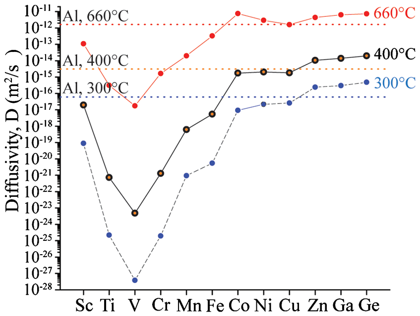
Calculated diffusivities for different solute elements at 573, 673, and 933 K (T m of Al) (reprinted with permission from Carl Hanser Verlag) 234
Of the transition elements, Zr seems to be one of the most promising for the design of lightweight high-strength high-temperature Al alloys. 227,234 Al3Zr phase not only impedes the dislocation motion but also refines the microstructure of Al alloys. With the addition of 0·15 wt-% Zr to Al–2% Cu alloy, the columnar grain structure changed to equiaxed structure. 247 Fasoyinu et al. 248 studied the effect of Zr, Sc and a combination of both on grain refinement of 356 alloy; effective concentration ranges of Zr and Sc of 0·37–0·69 and 0·39–0·75 (wt-%), respectively, are required to achieve a considerable grain refinement. Nevertheless, the phase and microstructure evolution of different Al based alloys (binary AlZr or multicomponent AlSiCuMgZr alloys) in the presence of this element has been keenly disputed.
Mahmudi and co-workers 249,250 investigated the effects of 0·15 wt-% Zr addition on the mechanical properties of A319 Al alloy. The hardness and wear resistance of the A319+Zr alloy were improved by 10% and 60%, respectively, compared to the A319 alloy, which were ascribed to the presence of the Al3Zr phase. Garat et al. 22 observed the presence of fine, semi-coherent ternary (Al–Zr–Si) dispersoids in the α-Al dendrites of (A356+Zr) alloy, which were formed during solution treatment above 773 K. They observed no binary Al3Zr phase in the microstructure. Ozbakir 251 also reported that with 0·15 wt-% Zr addition to A356 alloys, the eutectic ternary ϵ-(Al–Si–Zr) phase was formed instead of the peritectic binary Al3Zr phase. Prasad 252 observed the presence of both Al–Zr–Si and Al3Zr phases. Iveland 253 reported the presence of rod-shaped AlSiZr and AlSiZrTi precipitates in the heat treated microstructure of A356 alloy containing Zr and Ti. Recently, the presence of relatively coarse Al3Zr particles (diameters ∼600 nm) in (A356+Zr) as cast alloy was reported by Baradarani et al. 254 After solution treatment, very fine Al3Zr particles were observed in the microstructure, which led to the conclusion that either the Al3Zr particles were not completely dissolved during solution treatment or the particles re-precipitated after dissolution. Baradarani et al. 254 and Srinivasan et al. 243 stated that the dissolution–precipitation mechanism was promoted by the motion of grain boundaries, which activates dissolution ahead of the advancing boundary and precipitation behind.
Recent developments in Al–Si alloys and applications in engine components
The Al alloys that are usually used for the fabrication of engine cylinder heads can be classified into two main categories: 22,32,255
aluminium alloys containing 5–9 wt-% of Si, 3–4 wt-% of Cu (generally, treated to temper T5 or T7) (AlSiCu alloys, such as A319); and
aluminium alloys containing 7–10 wt-% of silicon and 0·25–0·45 wt-% of magnesium (generally, treated to temper T6 or T7) (AlSiMg alloys, such as A356).
The secondary alloys based on the 319-type Al alloy, with iron contents between 0·5 and 1% and moderately high contents of other impurities (e.g. zinc, lead), are particularly used in gasoline engine cylinder heads with fairly low service temperature and pressure. Primary alloys, based on the 319- and 356-type Al alloys with an iron content of less than 0·3%, are generally used for highly stressed (diesel engine) cylinder heads. Owing to limited contents of impurity elements (e.g. Fe, Zn), the primary alloys are more expensive than the standard secondary alloys. Aluminium alloys based on the 356-type alloy present high ductility and acceptable strength at ambient temperature. However, their strength significantly decreases above 473 K (200°C). In contrast, alloys based on the 319-type alloy exhibit higher yield and creep strength above 473 K (200°C), but present lower ductility. 22,27,32,255
In the last decade, several investigations have been carried out as regards the trade-off between various properties (tensile strength, ductility, creep resistance and fatigue resistance) of these two large families of aluminium alloys. Four Al–Si based alloys containing different Cu, Mg and Fe contents were studied by Chuimert et al. 27 The alloys are commonly used by the industry to produce cylinder heads. The results are summarised as follows:
In conditions similar to those encountered in service, the TMF lifetimes of the third and fourth alloys (with 0·15 wt-% iron content) were up to ∼5 times greater than those of the first and second alloys (untreated alloy with 0·7 wt-% iron content).
Jonason 256 investigated thermal fatigue resistance of four different Al–Si alloys (i.e. Al–8Si–3Cu–0·3Mg–0·7Fe/T5, Al–7Si–3Cu–0·3Mg–0·2Fe/T5, Al–7Si–3Cu–0·3Mg–0·2Fe/T6, Al–9Si–0·3Mg–0·2Fe/T6 (wt-%)) by cyclically heating and cooling the intervalve seat area between 313 and 503 K. The Al–9Si–Mg (wt-%)/T6 alloy was found to be the most fracture resistant alloy with significant tendencies to plastic deformation, the excellent fracture resistance being attributed to the higher ductility of the alloy. The Al–7Si–3Cu (wt-%)/T6 and Al–7Si–3Cu (wt-%)/T5 alloys were the second and third most fracture resistant alloys, respectively. Gundlach et al. 26 reported very interesting results on TMF resistance of fifteen different AlSi based alloys (319 and 356 Al alloys) fabricated by seven different foundries. Testing was done on 78 samples by imposing thermal cycles between 339 and 561 K under axial constraint. The average number of cycles to failure ranged from 162 to 1286 cycles. The lowest and highest fatigue lifetime belonged to the 319 Al alloys. The authors stated that ‘two unmodified 319 alloys had the lowest TMF lifetime; while two of the most highly modified 319 alloys displayed the highest TMF resistance’. Also, the overall TMF lifetime of 356 Al alloys, which was between 228 and 644 cycles, was lower than that of 319 Al alloys. During the thermal stress cycle, the stress–temperature diagram displayed a thermal stress hysteresis loop. In thermal cycling up to 477 K, the amount of thermal stress hysteresis was comparable in both 319 and 356 alloys; however, at higher thermal cycling temperature, 356 alloys displayed considerably larger thermal stress hysteresis. Superior elevated temperature strength and resistance to overaging of 319 alloys caused less plastic deformation with further benefit of narrowing of the thermal stress hysteresis loop. The elevated temperature strength of 319 alloys was ascribed to the presence of Cu-bearing phases.
Feikus 32 investigated the addition of 0·5 and 1 wt-% Cu to an Al–8Si–0·3Mg–0·1Fe (wt-%) alloy for manufacturing engine cylinder heads. No significant improvement in the room temperature yield strength of the alloys containing Cu was observed after conventional T6 treatment. The tensile strength and creep resistance of the alloys containing Cu were significantly improved in the temperature range of 423–473 K. A minor reduction in elongation was also reported. The effect of Cu addition on the coefficient of thermal expansion and thermal conductivity was negligible. It is interesting to note that the mechanical properties of both Cu-containing alloys (0·5 and 1 wt-%) were almost comparable. Subsequently, the impact of Ni (0·5 wt-%) and Mn (0·3 wt-%) on Al–7Si–0·4Cu–0·4Mg–0·4Fe (wt-%) alloy was extensively studied by Heusler et al. 69 The casting process and the solidification rate were simultaneously investigated. The addition of Ni improved the creep strength of the alloy; however, it had a rather small effect on the tensile strength at elevated temperatures. The fatigue strength of the Ni-containing alloy was approximately 20% higher than that of the AlSiMg alloy. It is important to note that when the casting process and the cooling conditions were not optimised, the improvement of mechanical properties by alloy optimisation remained marginal.
Lee et al. 257 studied the impact of Al3M (M = Ti, V, Zr) precipitates in AlSiCuMg alloy. They stated that these dispersoid phases enhanced the high temperature mechanical properties by effectively blocking the movement of dislocations. Thereafter, Laslaz and Garat 255 investigated the tensile and creep properties at ambient temperature, 523 and 573 K of three different alloys (A, B and C) having the following chemical compositions: A, Al–7Si–0·4Mg–0·15Fe–0·15Ti; B, alloy A+0·5Cu; and C, alloy A+0·5Cu+0·15Zr. The addition of copper to alloy A, which represents alloy B, led to an improvement in the yield strength and UTS at both ambient and elevated temperatures, without affecting the elongation. The addition of zirconium to alloy B, which gives alloy C, significantly increased the creep resistance, the deformation under constant load being reduced by 75%. This was attributed to the precipitation of fine thermally stable AlSiZr(Ti) dispersoids (<1 μm). However, Zr addition had almost no influence on the tensile properties. They also studied the effect of Mn and Mg additions in alloy C. The high temperature (∼523 K) mechanical strength improved with increasing Mn content from 0·1 to 0·3% and with increasing Mg content from 0·3 to 0·5%. They preferred not adding Ni in the alloy to avoid problems in recycling and to maintain the ductility of the part. To further improve the mechanical strength and creep resistance at elevated temperatures (503–653 K), Laslaz 227 investigated the effect of excluding Mg, and, instead, adding vanadium as another peritectic element. The results are presented in Table 6. These results confirm that tensile properties at 523 and 573 K of the alloys without Mg (alloys 7–9) are better than those of the alloys containing Mg (alloys 1, 2). At 573 K, the yield strength of the alloys without Mg (alloys 7–9) exceeds 50 MPa, while the yield strength of the alloys containing Mg (alloys 1–6) is below 50 MPa. The exclusion of Mg makes the ageing sequence change from β″, β′ binary phase (based on Mg2Si) and λ″, λ′ quaternary phase (based on Al5Cu2Mg8Si6) to θ″, θ′ (Al2Cu). It was found that θ″, θ′ (Al2Cu) phases can be more stable at high temperatures than β″, β′ (Mg2Si) and λ″, λ′ (Al5Cu2Mg8Si6). 227
Chemical composition, mechanical strength and creep properties of Al–Si alloys 227


* R
m: UTS (MPa), 
Moreover, the elimination of Mg and the phase Q (Al5Cu2Mg8Si6), which invariably reduces the melting point, allows one to increase the solution treatment temperature from T≤773 K to 788–798 K. The possibility of higher solutionising temperature has several advantages: greater homogenisation of copper phases, better modification of Si particles and more complete precipitation of zirconium dispersoid phases. 187,199,227 Garat et al. 22 confirmed the positive effect of Mg exclusion and the presence of dispersoid phases on the tensile properties and creep strength.
Nevertheless, Garat 258,259 stated subsequently that adding a small amount of Mg (0·1–0·2 wt-%) to AlSiCu-type alloys is required to improve the LCF strength and room temperature tensile strength. Adding Mg and V together also had a synergic effect on creep strength (at 573 K). 258,259 More recently, Iveland 253 compared the creep resistance and LCF behaviour of A356, (A356+0·5Cu), A319 and (A356+0·5Cu+0·5Hf) alloys. They observed the presence of ribbon- or nanobelt-like hafnium compound in the α-Al matrix which is a unique microstructure. LCF strength of (A356+0·5Cu+0·5Hf) alloy was the best, and A319 alloy showed better LCF strength than the rest. This discovery certainly opens interesting possibilities for niche applications, but not for the high volume automotive market because of the prohibitive cost of hafnium.
Characteristics of the engine block
The piston slides up and down in the cylinder bore and the piston ring is always in contact with the cylinder bore wall. Therefore, wear resistance and low coefficient of friction (between cylinder bore and piston ring) are major characteristics required for engine block materials. 260 Wear is damage on a solid surface with a progressive loss of material as a result of relative movement of that surface with respect to the contacting substance. It is closely related to friction and lubrication. Wear of cylinder bores is enhanced under low temperature operation of engines (while warming up). At low temperature, the vapour in combustion gas can condense as water drops on the bore wall. Dissolution of combustion products in the water drops promotes acid formation (e.g. sulphuric acid and nitric acid), which locally degrades lubrication and enhances abrasion. 261
As previously explained, friction between engine components consumes a significant fraction of total vehicle power; over 50% of this power loss is related to the frictional loss between cylinder bores and the piston assembly. 46,48 It has been reported that a 10% reduction in friction loss can improve fuel economy by 3%. 44 Therefore, frictional loss between the cylinder bore surface and the piston ring is one of the major parameters to be considered in developing alternative materials for cylinder blocks. 46,48
Historically, cast iron was used in engine blocks; however, demands to improve fuel economy and reduce greenhouse gas emissions necessitate alternative materials for and design improvements of engine components. Substitution of cast iron in cylinder blocks with a lighter and more thermally efficient material can be one of the best options for improving fuel economy. The application of Al–Si hypoeutectic (e.g. 319- and 356-type) alloys in engine blocks contributes to a considerable weight reduction (up to 45%) with the further benefit of improved thermal conductivity (three times better than cast iron). 262–265 However, this substitution has not been an easy task for the automotive industry. In 2002, about 50% of all vehicle engine blocks were produced using Al–Si alloys, but only ∼10% of them were Al–Si engine blocks without cast iron cylinder liners. 266 Al–Si hypoeutectic alloys do not satisfy the tribological surface requirements of cylinder bore walls; the cylinder bore wall must be modified or replaced with a more appropriate material. 267,268 The cylinder bore wall is generally fortified with either a ‘cast-in’ or ‘pressed-in’4 cast iron cylinder liner to meet the required surface characteristics (see Fig. 22). Grey cast iron liners have appropriate hardness, low cost and ease of production, and are regularly used in today’s passenger cars. 269
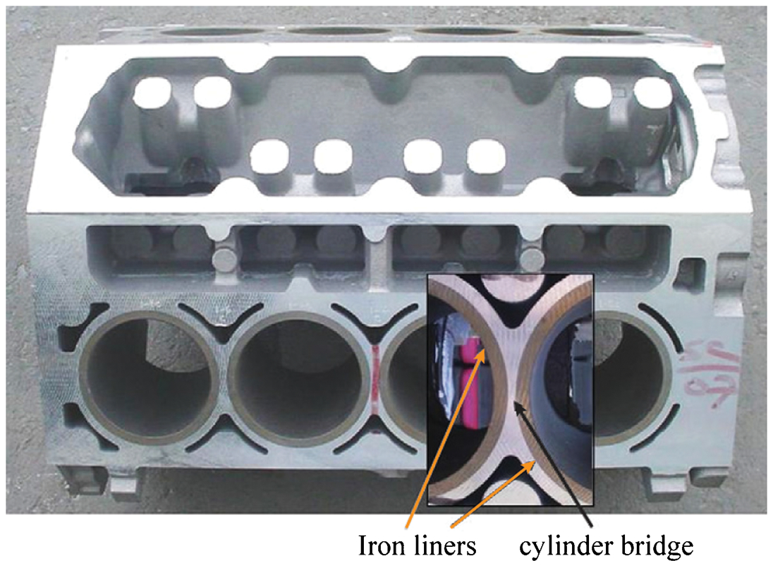
V-8 engine block with cast-in liners (reprinted with permission from Elsevier) 269
While liner-equipped engines are currently the most common and cost-effective solution, they have some intrinsic deficiencies (e.g. size, thermal conductivity, etc.) compared to the potential alternative liner-less Al–Si alloy cylinder blocks. 268,270
Appropriate heat extraction necessitates a suitable thermal contact (metallic bonding) between the liner and the surrounding cast Al–Si alloy; nevertheless, the contact between the iron liner and Al engine block is only a mechanical one.
While the precise matching of the liners with the piston rings plays a vital role in engine performance, different thermal expansion coefficients of Al–Si alloy cylinder block and cast iron liner might cause distortion in the liner.
Moreover, cast iron liners increase the size (inter-bore distances) and weight of engines (particularly in engines with a large number of cylinders).
Improving the tribological characteristics of Al–Si cylinder bore surfaces by other alternative approaches, instead of using cast iron liners, has attracted great interest. Four highly promising alternative procedures for modifying the tribological properties of cylinder bore surfaces are: 46,48,271
Using hypereutectic Al–Si alloy cylinder blocks.
Using aluminium matrix composites which are reinforced by particles or fibres in the production of either entire cylinder blocks or cylinder liners to be positioned in hypoeutectic Al–Si alloy cylinder blocks.
Coating the cylinder bore surfaces of hypoeutectic Al–Si alloy cylinder blocks with thermal spray.
Using electrochemically deposited coatings on the cylinder bore surfaces of hypoeutectic Al–Si alloy cylinder blocks.
Each of these procedures is briefly described in the following.
Hypereutectic Al–Si alloy cylinder block
Use of monolithic hypereutectic Al–Si alloy cylinder blocks was the earliest alternative approach to eliminate cast iron liners. Porsche, as a pioneer, used a hypereutectic Al–Si alloy cylinder block in the 1960s. The first application of a hypereutectic Al–Si alloy in a commercial engine was in 1971, when Reynolds A390 aluminium alloy was used by General Motors in the liner-less Vega block. 73,272 Hypereutectic Al–Si engine blocks have significantly evolved since the Vega. Some car manufacturers which are using Al–Si hypereutectic alloys are Mercedes, Audi, BMW, Volvo and Honda. 73,270 Many different hypereutectic Al–Si alloys for cylinder blocks are produced in the world market with specific trade names (e.g. Alusil®, Lokasil®, Silitec®, DiASil, Mercosil, ALBOND®). For instance, Mercosil, as a copper-free hypereutectic Al–Si alloy, is utilised in Mercury Marine’s cylinder blocks. More uniform distribution of primary silicon particles in Mercosil gives better tribological characteristics compared to 390 Al–Si alloy. 270
Chemical composition and mechanical properties of 390·0 hypereutectic Al–Si alloy are presented in Tables 2 and 3, respectively. It is well known that by adding Si to Al alloys, beyond the eutectic composition (at ∼12·6 wt-% Si; see Fig. 11), primary silicon particles crystallise out in the microstructure of the Al–Si hypereutectic alloy which consequently enhances the hardness of the alloy and provides the required tribological surface characteristics. In the absence of silicon particles, premature wearing of Al cylinder bore surfaces by the piston rings could rapidly occur; consequently, the compression of the engine will be lost which results in engine failure. Therefore, a uniform distribution of primary silicon particles in the alloy is the key criterion for wear resistance of cylinder bores. 268
The piston ring slides over a layer of both the primary silicon particles and lubricant without touching the Al matrix in a hypereutectic Al–Si alloy cylinder bore. To make sure that the piston ring rides over the primary silicon particles and not on the Al matrix, a chemical etching process is generally applied to the cylinder bore surface. The etching process leads to silicon particles protruding a slight distance above the aluminium cylinder surface. 270,273 However, Dienwiebe et al. 274 stated that the height of both Si grains and Al matrix are at the same level after a short running time. They proposed that wear particles from various sources (e.g. silicon fragments, iron oxide and iron nitride particles from the piston ring, and carbonaceous particles) are mixed and placed in the soft Al matrix; the piston ring slides over a layer of wear particles and primary Si phase.
Some mechanical/physical properties of A390 Al alloy are compared with other competing engine materials in Fig. 9. Several benefits are associated with hypereutectic Al–Si alloy cylinder blocks compared to cast iron block/liner. These alloys provide not only the required tribological surface characteristics but also improved thermal conductivity (up to three times more) compared to cast iron. The HCF strength of Mercosil hypereutectic Al–Si alloy was ∼90 MPa, which was ∼50% higher than that of hypoeutectic Al–Si alloy. 270 Low coefficient of thermal expansion, high hardness and being highly recyclable are the other major characteristics of the hypereutectic Al–Si alloys. 268 The Cagiva group reported that the Husqvarna engine equipped with Mercosil alloy showed approximately 6% more horsepower than the honed Nikasil® electroplated bore. 270
In spite of all of these advantages, certain characteristics of the hypereutectic Al–Si alloys prevent their widespread application in the manufacturing of engine blocks. Their applications have been mainly limited to German engines. 73 The casting process of the hypereutectic Al–Si alloys with homogeneous and uniform properties is really difficult. The tribological surface characteristics of hypereutectic Al–Si cylinder bores are strongly dependent on the even dispersion of Si particles. Additionally, manufacturing of hypereutectic Al–Si alloy cylinder blocks is an expensive process; these alloys require the addition of expensive elements (e.g. Ni) to improve the mechanical properties. They also need to be chemically etched to protrude primary silicon particles from the Al cylinder bore surface, which increases processing time and costs. 275,276
Reinforced Al–Si alloy cylinder block/bore
Use of metal matrix composites (MMCs) is the second possible alternative for replacing the traditional aluminium cylinder block equipped with cast iron liner. MMCs can be used to produce either the entire cylinder block, or only a cylinder liner to be placed into a hypoeutectic Al–Si alloy cylinder block. 265,277 An MMC is made up of at least two distinct phases, properly distributed to realise unique combinations of properties which are not attainable by the individual components. It is composed of a matrix and reinforcements (e.g. fibrous or particulate phase), in which the reinforcements are surrounded by the matrix. 265
Extrusion of an Al–Si alloy in which reinforcement ceramic particles are already dispersed, and infiltration of liquid metal through a ceramic preform by squeeze casting are the two common methods to produce MMC cylinder liners. In the squeeze casting process, pressure is applied on the liquid metal in such a way that it is forced to infiltrate porous fibre preforms.
Al–Si alloys can be reinforced by both hard and/or soft phases. The major purpose of adding hard ceramic phases is to improve material’s hardness, with the further benefit of enhancing the wear performance. SiC and Al2O3 are the two most common hard phases used to reinforce Al–Si alloys. As illustrated in Fig. 23, addition of 6 vol.-% SiC appreciably improves the wear resistance of Al–12Si (wt-%). 278 Soft secondary particles/fibres (e.g. graphite and MoS2) can also be added into the matrix to decrease the friction, consequently resulting in a potential reduction of wear. Figure 24 illustrates the normalised wear data of Al alloy–graphite composites; the wear rate is considerably reduced with increasing graphite content up to 3 wt-%, after which it remains almost constant. 279 Furthermore, cylinder bore surfaces strengthened with hybrid phases of alumina and carbon can experience even better wear resistance. 280,281 As illustrated in Fig. 25, the wear resistance of an Al–12Si (wt-%) alloy reinforced with 17 vol.-% short alumina and 7 vol.-% carbon fibres was equal to that of a cast iron cylinder bore; and was significantly higher than that of an Al–Si hypereutectic cylinder bore. 282
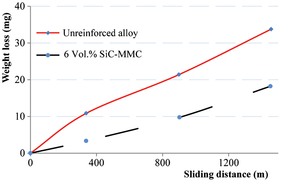
The effects of addition of 6% SiC particles on wear loss of Al–Si alloy 278
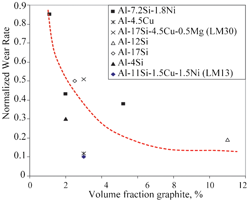
ageing wear rate of Al–graphite composites 279
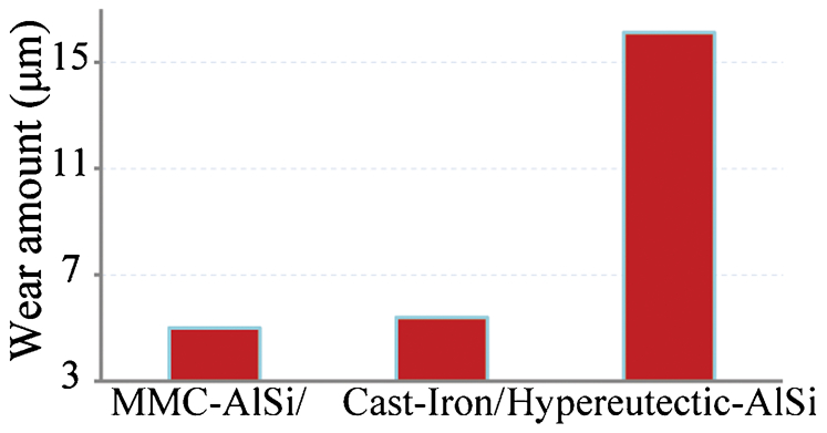
Wear amount of different cylinder bore material 282
Toyota, as a pioneer in the use of MMCs in cylinder blocks, successfully manufactured MMC lined cylinder bores. The preform of the MMC liner was composed of mullite particles and alumina–silica fibres. 261,283 Honda also produced a hybrid MMC preform composed of short carbon and alumina (Al2O3) fibres, which was subsequently infiltrated by aluminium. 279 Takami et al. 283 compared the characteristics of two different types of engine block made by Toyota: a cast iron lined Al engine block (1ZZ-FE engine) and an MMC lined Al engine block (2ZZ-GE engine). The bore-to-bore distance was decreased from 8·5 mm in the 1ZZ-FE engine to the shortest possible distance of 5·5 mm in the 2ZZ-GE engine. Using the new MMC lined cylinder block (2ZZ-GE engine) allowed an enhancement of the piston bore diameter and reduction of the piston stroke, which help to improve the engine cycling capacity. Consequently, the horsepower and the torque of the MMC lined cylinder block (2ZZ-GE engine) were, respectively, 26·17% and 4·65% superior to those of the cast iron lined cylinder block version (1ZZ-FE engine). 283
MMC lined cylinder blocks provide several advantages such as being lighter, showing lower thermal deformation, being more thermally conductive and having lower bore-to-bore distance compared to cast iron liners. The weight of a cast iron liner and MMC liner was reported to be 9 and 6·5 kg per block, respectively. 58 A Honda cylinder block produced using Al alloy fortified with MMC was ∼50% and ∼20% lighter than the cast iron engine block and the Al alloy engine block equipped with cast iron liner, respectively. 277 Moreover, MMC lined cylinder blocks can be more affordable and easier to process than hypereutectic Al–Si alloy cylinder blocks (e.g. Alusil®). Nevertheless, the higher production costs, uneven distribution of reinforcement, difficulty in melt infiltration, post-casting machining and recyclability problems prevent the mass production of MMC cylinder blocks. 277,283
Electroplating Al–Si alloy cylinder block wall
The third potential alternative to provide the necessary surface requirements for cylinder bores is to deposit high hardness, wear resistant materials by electrochemical processing. The most common electroplating processes, which are either currently being used or being evaluated, are nickel ceramic composite coating (NCC) 46 and plasma electrolytic oxidation coating (PEO). 284,285 The PEO process is also known as micro-arc oxidation (MAO). 286,287 The details of the NCC and PEO/MAO processes have been described by Shrestha 288 and by Yerokhin 286 and Krishtal, 266 respectively.
In an Ni/SiC composite, Ni adheres to the cylinder bore surface to hold and support the silicon carbide particles. These reinforcement particles provide the required tribological surface characteristics and hardness for the cylinder bore. 46,289 The size of SiC particles is 3–7 μm and corresponds to a volume fraction ranging between 8 and 17% of the coating. The hardness and thickness of the coating are usually 500–600 HV and 70–75 μm, respectively. 48,284 In addition to SiC, BN and Si3N4 are other ceramic particles that can be incorporated in coatings produced using the NCC process. Nikasil®, as a trademark of Ni/SiC composite, has been used by some automakers (e.g. BMW and Jaguar). 46,290 However, nickel based coatings are highly sensitive to the presence of sulphur in gasoline; over time, sulphur can break down the coating. Therefore, BMW and Jaguar both decided to switch from the Nikasil cylinder liners to cast iron liners. 290 Nevertheless, cylinder bores coated with Ni/SiC composite have been successfully employed where fuel quality is not a concern; 284,290 for instance, they have been used in Italy (Ferrari), Germany (for sports cars at a level of 90 000 vehicles per year) as well as in France (Citroën). 266
In the PEO process, aluminium transforms to aluminium oxide when a high voltage (>100 V) bipolar pulsed current circulating in an alkali electrolyte produces a plasma discharge on the surface of the substrate. The coating is mainly composed of α-Al2O3, γ-Al2O3 and 3Al2O3⋅2SiO2 (mullite) phases with two distinct layers. The outer layer, with a microhardness ranging between 500 and 1000 HV and having a porosity level >15 vol.-%, is generally removed by diamond honing; otherwise it could dramatically affect the friction coefficient and wear resistance. 48 The inner layer (with a thickness of 15–30 μm) has excellent wear and corrosion resistance, a very hard surface (microhardness of 900–2000 HV) and superior adhesion property to the substrate. Previous studies illustrated that PEO coating on Al–Si alloys leads to lower friction and superior wear resistance in comparison to cast iron 291 and Nikasil. 284
The main advantages of the electroplating process are: low friction coefficient, high corrosion resistance, high hardness, high wear resistance, possibility of decreasing the distances between cylinder bores and stronger bonding with the substrate material. 46 Besides all of these advantages, a complex and costly process is the major limitation of electroplating processes. The necessity for selective area coating on the cylinder block requires more complicated equipment to carry out localised deposition or masking. Moreover, the high hardness of the applied coating requires specific machining tools for the honing process; it is worth mentioning that honing is an essential process to reach an appropriate coating thickness. 48,260 As mentioned earlier, nickel based coatings can be susceptible to the presence of impurity elements in fuels (e.g. sulphur). Furthermore, the cost of raw materials (in particular Ni) is another main limitation for the NCC process which hinders the feasibility of mass production. 260,290
Thermal spray coating of Al–Si cylinder block wall
Another approach to improve the wear resistance of the cylinder bore is to deposit a layer of an appropriate material onto the cylinder bore wall with a thermal spraying process. Atmospheric plasma spraying (APS), high velocity oxy-fuel spraying and electric wire arc spraying are the major thermal spraying processes able to apply a coating on cylinder bores. The APS process has been utilised in mass production to coat cylinder bores over the past 10 years. 292 A description of thermal spray processes of cylinder bores and coating materials has been elaborated upon elsewhere. 271,292–294
Coating of a cylinder bore wall by the thermal spray process is implemented in several steps. After casting the Al–Si cylinder block with a rough diameter, the cylinder bore is pre-machined to a certain diameter. The surface is thoroughly cleaned to remove oil and residues from the machining process. Thereafter, one of the following three processes is applied to activate the bore surface: grit blasting, high pressure water jet or mechanical activation. 292 The purpose of the activation process is to break the aluminium oxides from the surface and to obtain a sufficient roughness. 295 Since there is no metallurgical bond between coating and substrate, this roughening can increase the bond strength. 292 The required bond strength value has been reported to be more than 30 MPa. 292,296 The advantages and disadvantages of the aforementioned activation processes have been compared elsewhere. 267,292
The next step is to deposit the coating materials by means of one of the aforementioned thermal spray processes. Some of the most commonly used APS coatings, which are generally iron based materials, are listed in Table 7. Depending on the working condition of the engine, one of these coating materials could be an appropriate choice. Adding ceramics (e.g. Al2O3/ZrO2) to the ferrous coating materials improves the scuffing and wear resistance; however, they do not affect the hardness. This class of coatings, which are MMCs, is useful when high abrasive wear resistance is required. 14Cr–2Mo steel (XPT627) as the base metal of MMC is suitable for corrosion resistant cylinder surfaces. The corrosion resistance of coating materials can be suitable where the presence of impurity elements in fuels (e.g. sulphur) is a concern. Mixing the alloy powders with carbides can considerably enhance the hardness. To produce hard and corrosion resistant coatings, carbides can be mixed with the corrosion resistant matrices. Honing with diamond ledges to reach the appropriate diameter is the final step of the thermal spray coating process. The details of the process, coating materials, microstructure and thickness of the coatings have been elaborated by Ernst et al. 292
Some of the most commonly-used APS coating materials (copyright © 2012 SAE International and SAE of Japan; reprinted with permission) 292
The results of testing an MMC coating material at AVL Austria in a four cylinder diesel engine (50 kW L−1, 150 bar) are summarised in Figs. 26 and 27. As illustrated in Fig. 26, the oil consumption (test duration up to 250 h) can be decreased appreciably by MMC plasma coating of the cylinder bore. In Fig. 27, the radial wear of the plasma coated cylinder bore and the first and second piston rings is compared with that of those parts made with cast iron. In the engine equipped with the plasma coated cylinder bore, the measured wear in all parts was considerably lower.
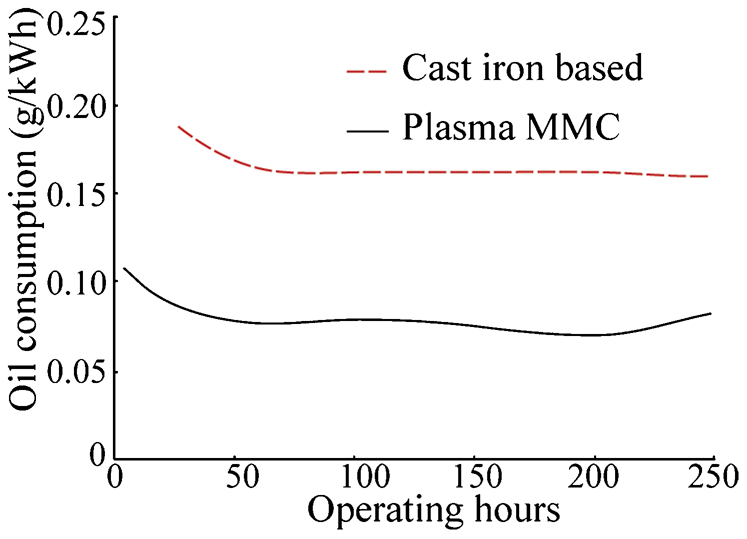
Comparison of the oil consumption with standard cast iron liners and plasma coated cylinder liners 297
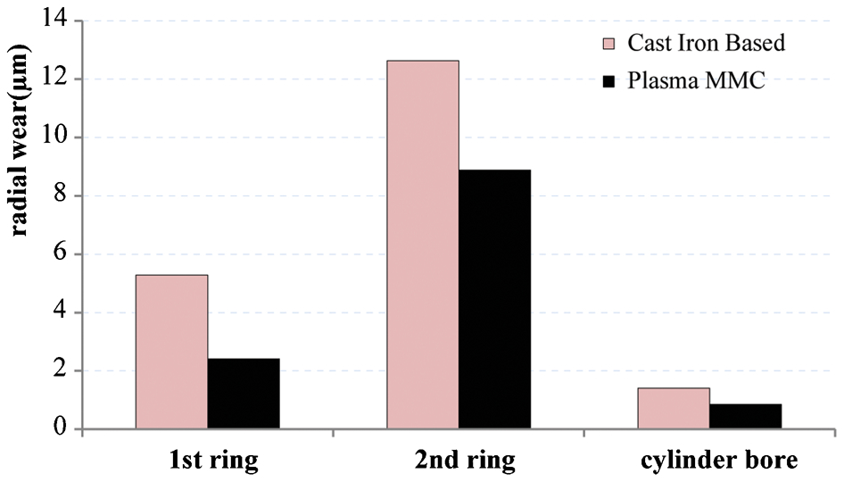
Radial wear on 1st and 2nd piston ring as well as cylinder bore at the top ring position compared for cast iron and plasma coated cylinder liners 297
The major advantages of thermal spray coated Al–Si cylinder bores (compared with cast iron liners) can be summarised as follows: 271,295
It is possible to reduce the bore-to-bore distance of cylinders.
The wear resistance of the plasma sprayed coating is considerably superior to that of the cast iron liner.
The friction between cylinder bore and piston rings can be considerably reduced (up to 30%).
Oil consumption can be significantly decreased.
The contact between the Al cylinder bore surface and the coating materials is mainly by mechanical bonding. Therefore, if the thermal spray coating is not appropriately implemented, the coating will be delaminated over time and subsequently separated from the Al cylinder bore surface. 298 Thermal spray coatings are susceptible to the presence of impurity elements in fuels (e.g. sulphur) which introduce the possibility of corrosive attack. 299 Overheating of the Al cylinder bore is another concern during the high velocity oxy-fuel thermal spray process which might damage the substrate. Finally, it has to be taken into account that thermal spray coating equipment needs high initial investment. Despite all of these limitations, thermal spray coating processes are the most recent and the most promising surface modification technologies for Al–Si alloy cylinder blocks, and are potentially suitable for mass production. 260,271 An overview of qualified engines with plasma coating is given in Table 8.
Qualified engines with plasma coating in industrial production 296
Comparative analysis of the alternative approaches for iron lined cylinder blocks
A more thorough review on alternative approaches for iron lined cylinder blocks has been done by Lenny. 260 In order to rank the four mentioned alternative approaches and select the best choice, he compared ten different characteristics: ‘Previous Applications, Wear Resistance, Scuffing Resistance, Thermal Conductivity, Friction between cylinder block and piston rings, Fuel Economy, Engine Emissions, Manufacturing Costs, Engine Performance, and Mass Production Feasibility’. Comparison results illustrated that a hypoeutectic Al–Si cylinder block equipped with an iron liner is still the best alternative since it is the most affordable choice. However, social impetus for fuel economy and emissions reduction necessitates application of other alternatives instead of cast iron lined Al–Si cylinder blocks. Hypoeutectic Al–Si cylinder blocks equipped with thermal spray coating proved to be the most promising alternative approach in comparison, which is potentially suitable for mass production. Electrochemical deposition coating on hypoeutectic aluminium bore surfaces, hypereutectic Al–Si alloy cylinder blocks and fibre reinforced aluminium matrix composite cylinder blocks are other promising alternatives. 260
Summary
An increasing social demand for a reduction in fuel consumption and gas emissions calls for the urgent substitution of cast iron with lighter metals (e.g. Al–Si alloys) in the production of engine components. Al–Si alloy cylinder heads are already used for engines with lower firing pressure and temperature peaks, such as gasoline engines. On the other hand, higher service temperatures and stress amplitudes, which are required to improve engine performance, might cause fatigue failure in Al–Si alloy cylinder heads. The thin walls adjacent to the water ducts in the valve bridge of cylinder heads are the most critical locations for TMF crack initiation.
To reach the optimum pressure and temperature levels desired to ensure efficient functioning of cylinder heads without the need to develop new materials, the existing capabilities of Al–Si based alloys have to be improved by optimisation of either production process or chemical composition. The fatigue lifetime of Al–Si alloys is more affected by the actual casting processes than by alloy chemistry. This is evident in defect-limited specimens, where the initiation of fatigue cracks is greatly delayed. The most detrimental defects of cylinder heads are porosity and inclusions. Thus, measures must be taken to fortify Al–Si alloys and minimise the above-mentioned defects which accelerate cracking. To this end, dispersion and precipitation hardening are the major processes adopted in strengthening Al–Si hypoeutectic alloys. Some transition elements, which can be precipitated as fine, stable, coherent particles, can significantly improve the TMF performance. In addition, heat treatment processes play a vital role in microstructural modification and mechanical properties. The lamellar morphology of brittle Si particles can be modified to fibrous form by suitable solution treatments. A 20 K increase in the temperature of the solution treatment (from 753 to 773 K) significantly enhanced the strength of hypoeutectic Al–Si alloys containing Cu and Mg. For those Al–Si alloys containing high Cu and Mg content, the duration and temperature of the solution treatment are still debated, and a unique combination of time and temperature might have to be determined for every single chemical composition.
In this study, four possible alternative approaches for cast iron cylinder liners were reviewed. Comparison of the results illustrated that equipping hypoeutectic Al–Si cylinder blocks with iron liners is still the best option. The results also demonstrated that coating hypoeutectic Al–Si cylinder blocks using a thermal spray process can be the most promising alternative approach. Table 9 lists the major engine components produced by Al–Si alloys.
The major engine components produced by Al–Si alloys
Future directions
The magnesium and copper content of Al–Si hypoeutectic alloys needs to be optimised. Copper improves the high temperature strength of Al–Si alloys. Nevertheless, it can significantly increase casting defects. Adding Mg to Al–Si alloys containing Cu improves room temperature strength, but its effect on high temperature strength has recently been argued. Moreover, in the Al–Si alloys containing high Cu and Mg contents, the solution treatment still requires comprehensive experimental study to achieve the optimal mechanical properties.
The beneficial effect of some transition elements on TMF performance of Al–Si alloys has been disputed and needs further investigation.
Even though cast iron lined cylinder blocks satisfy the required tribological characteristics and mechanical properties, further research and experimentation are required to find an optimum alternative approach to strengthen the cylinder bore walls of Al–Si alloy engine blocks in order to improve thermal conductivity and reduce vehicle weight.
Footnotes
Acknowledgements
The authors are grateful for the financial support given by the Natural Sciences and Engineering Research Council of Canada (NSERC) and Rio-Tinto-Alcan (RTA). Special thanks to Fred Major from RTA who helped to arrange the financial support. Thanks also to Mihriban Ozden Pekguleryuz, X. Grant Chen, Amir Rezaei Farkoosh, Carl Blais and Mathieu Brochu for fruitful discussions.
1
All chemical compositions are given in weight percent (wt-%) hereafter, unless otherwise stated.
2
T m is the absolute melting point of the aluminium alloy (T m = 888 K).
3
Dimensional change induced by solid phase transformation.
4
The cast iron liners can be as a core of the mould in the casting process (cast-in liner) or inserted in the machined cylinder bores (pressed-in liner).