
Abstract
Fibre-reinforced hydrogels with high optical transparency are an emerging composite material with great promise to enable new applications, such as a transparent wound dressing with custom tuned mechanical properties that provides desirable mechanical and physical properties along with optical clarity for facile wound inspection. Stand-alone hydrogels are an important class of materials comprising a cross-linked polymer network surrounded by a water matrix. However, their mechanical properties are typically very modest compared with other materials. While significant research is going on in parallel in the fields of hydrogels and reinforcement fibres, researchers are only starting to scratch the surface of the possibilities of combining the two. This report provides a review of natural and synthetic reinforcement fibre research with special emphasis placed on nanofibres. These provide the added benefit of transparency by being much smaller than the wavelength of visible light. A review of hydrogel materials is also presented. The mechanical properties, optical properties and biological functionality of hydrogel systems are also described. Ocular, load-bearing tissue, wound management and sensing/device applications are all discussed. Transparent fibre-reinforced hydrogels provide a compelling potential solution to enable advanced functionality, in particular in the wound care and optical application areas.
Introduction
Hydrogels are an important class of materials comprising a cross-linked polymer network surrounded by a water matrix. Hydrogels typically exhibit excellent water absorbency properties, as they sometimes consist of more than 99% water. The water bearing capability arises from the functional groups present on the cross-linked polymer including amino, carboxyl and hydroxyl groups. The density of hydrophilic groups and the cross-link density both have a strong impact on the water capacity and the stiffness of the hydrogel. Hydrogels can contain engineered polymers, natural fibres, or a combination of synthetic and natural polymers. The synthetic polymers used in hydrogels include polyvinyl alcohol, polyethylene glycol, acrylate polymers and copolymers, silicones, polyacrylamides, polyethylene oxide, polyvinylpyrrolidone, poly(hydroxyethyl methacrylate), poly(methyl methacrylate) and many others. The natural polymers (sometimes referred to as bio-polymers) used in hydrogels include polymers such as cellulose, collagen, alginate, chitin, silk, hyaluronic acid (HA), fibrin, agarose and chitosan. The type of polymer selected and the degree of cross-linking can be engineered to control the desired mechanical properties of the hydrogels to make them suitable for specific applications. Hydrogels have been used in many different types of applications, such as medical and biosensors that respond to specific chemical or biological molecules; microarrays that can be used to immobilize cells locally on a substrate; contact lenses; medical electrodes; tissue engineering of various organs (e.g. collagen hydrogels for the liver, skin and blood vessels and other hydrogels for bone and cartilage); controlled drug delivery; and diagnostic imaging applications. Many of the applications would benefit from optical transparency. Apart from the obvious optical clarity requirement in contact lenses, transparency is also desirable in wounds dressed with hydrogels (e.g. burn wounds or ocular wounds), in sensors that rely on fluorescent markers embedded within hydrogels, or in ocular prostheses, which begin their reconstructive journey as hydrogels.
While synthetic polymers would be suitable hydrogel constituents in some applications, natural fibres may be more suitable for some medical and biological applications. Due to the enormous importance of the aforementioned and other applications for medical and biological purposes, this review manuscript was prepared with the goal of informing the reader about several areas related to fibre-reinforced hydrogels with high optical transparency. Reviews of important natural and synthetic fibre reinforcements are given in Natural fibres and Synthetic fibres sections, along with related synthesis methods in the Synthesis of natural and synthetic fibres section. The Hydrogels section focuses on some of the more prevalent hydrogel matrices and their properties. Fibre-reinforced hydrogels and Optical properties: transparency, refractive index match sections focus on the science, properties and applications of transparent reinforced hydrogels. The applications section focuses on applications such as ocular (contact lenses, corneal prostheses), load-bearing tissue (cartilage, tendons), wound management and sensing/device applications. Finally, the paper concludes with a future perspectives section, which discusses the prospects for fibre-reinforced hydrogels with high optical transparency.
Natural fibres
Fibres derived from natural sources are appealing as reinforcement materials owing to their abundance, high specific strength and modulus, low density, non-toxic, nonabrasive, combustible and biodegradable properties. 1,2 Because these materials strike a practical balance between cost and performance, 3 and because they are environmentally friendly, they are increasingly being considered as reinforcements in polymer composites and hydrogels for various applications. Types of natural fibres of increasing interest for hydrogel applications include, but are not limited to, cellulose, chitin, alginate and spider silk. The structure and properties of these natural fibres are discussed below. Other types of natural fibres, such as bamboo, hemp, ramie and flax are mentioned, and reviews of these natural fibres and their uses in composites can be found elsewhere. 1,4–7
Cellulose fibre
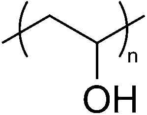
Cellulose, the most abundant natural polymer, 8,9 is composed of linear polymer chains of β-1,4-linked glucose residues. The structural repeat unit of cellulose is shown in Fig. 1. The six hydroxyl groups per mer in cellulose make it amenable for chemical functionalization to change its properties. For example, acetylation has been shown to change its optical properties. 10 Most of the cellulose on our planet is made by vascular plants, such as trees. Wood derived celluloses also have lignins and hemicelluloses intimately mixed with the cellulose. Other than vascular plants, cellulose is also made by natural organisms such as algae, slime mould, several bacteria and tunicates. 11 Of all the sources of cellulose, bacterial (sometimes referred to as microbial) cellulose and plant based (e.g. wood and cotton) cellulose have been widely studied in recent years because of its interesting wound care, tissue engineering, structural and optical properties. 9,10,12–26 Cellulose fibres also have advantageous gas barrier properties in addition to their excellent transparency. 27
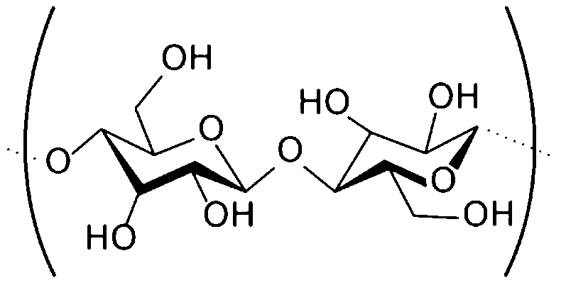
Structural repeat unit of cellulose
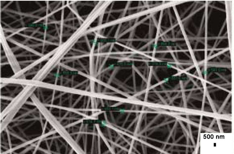
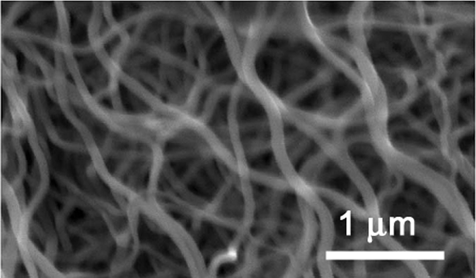
Cellulose is a polymorphic polymer. Depending on the source and processing method of the cellulose, the molecular weight, crystal structure and percent crystallinity can vary greatly, which in turn substantially impact the properties of the material. Cellulose I is most commonly produced in nature by plants and is a crystalline form of cellulose in which the cellulose chains align parallel to each other. 11 Cellulose I is also produced by bacteria such as Acetobacter xylinum. In those bacteria, nanofibres are ejected from a series of pores on the cell wall and aggregate to form ∼15–40-nm ribbon shaped long fibres. A wet and supercritical CO2-dried mat of bacterial cellulose is shown in Fig. 2. Cellulose I contains two crystalline sub-allomorphs in varying amounts that are termed Iα and Iβ. The crystal packing, hydrogen bonding and molecular conformation of Iα and Iβ differ, which could influence the structural and optical properties. 11 Bacterial and algal cellulose are Iα rich, with bacterial cellulose consisting of 100% pure Iα form. In contrast, cellulose found in wood, ramie, cotton and tunicates is rich in the Iβ form. Note that cellulose Iα exists in a metastable state and when annealed undergoes a phase transformation to the Iβ form. Another crystalline state of cellulose that has an anti-parallel chain arrangement is termed cellulose II. Cellulose II is produced by some organisms and mutants of A. xylinum, which normally produces cellulose I. Cellulose can also exist in an amorphous state. The cellulose produced naturally can contain varying amounts of Cellulose I, Cellulose II and amorphous cellulose and have vastly different properties depending on the cellulose phase and morphology of the material.
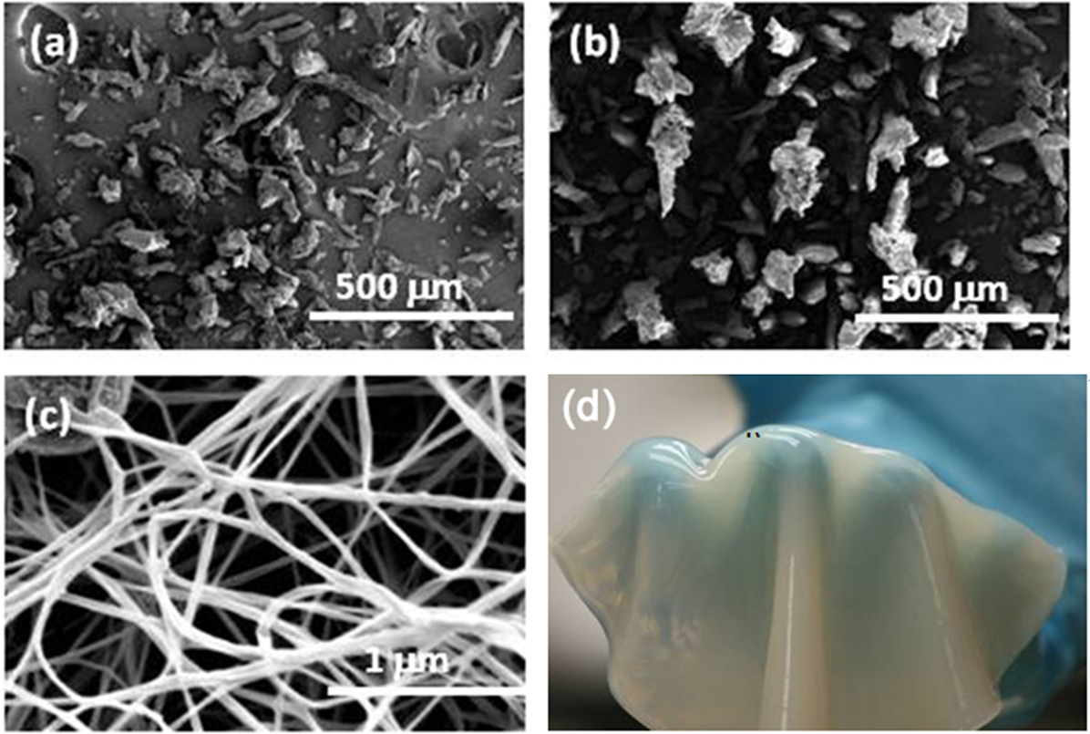
a Plant based cellulose powder, b cotton based cellulose powder and c supercritical CO2-dried mat of bacterial cellulose as viewed in the SEM; d mat of bacterial nanocellulose fibres over a person’s hand (for size reference) 29
One interesting method to produce cellulose nanofibres is a top-down method, which involves high power sonication. Zhao et al. 28 showed that sonication can be used to generate ultrafine cellulose nanofibres from wood and other natural sources. Sonication produces uniformly sized nanofibres compared to other methods with the resultant fibres in the 25–120 nm diameter range. The process is environmentally friendly, scalable, and facilitates retention of the hierarchical structure of natural materials.
Of particular interest for this paper are celluloses that are naturally made into nanofibres or can be processed into nanofibres, because nanofibres are expected to provide a good route to high strength and high transmittance hydrogels. An excellent review of cellulose nanofibres and nanocomposites is given by Eichhorn et al. 18 Cellulose nanofibres that are particularly relevant to incorporation in a hydrogel as a reinforcing element are briefly described below. Nanofibre mats (also known as pellicles), such as those shown in Fig. 2, could be utilized as reinforcing agents in hydrogels. The density of the mat can be controlled by optimizing the growth time. Shorter growth times lead to thinner, less dense pellicles. One could also employ top-down processing methods to produce cellulose nanofibre mats. For example, high power sonication was shown to be very effective in extracting nanofibres from natural materials including cotton, bamboo, wood, ramie and hemp. 30 Furthermore, nanofibrillated cellulose (NFC) produced by dissolving wood pulp fibres and grinding them iteratively can also be used to generate mats of cellulose nanofibres. 9 Finally, directed assembly has also recently been demonstrated to be a viable technique for producing patterned structures made of bacterial cellulose. Microfluidic channels with flowing media containing cellulose producing bacteria were utilized to create novel web and linear patterns of bacterial cellulose fibres (Fig. 3). 31
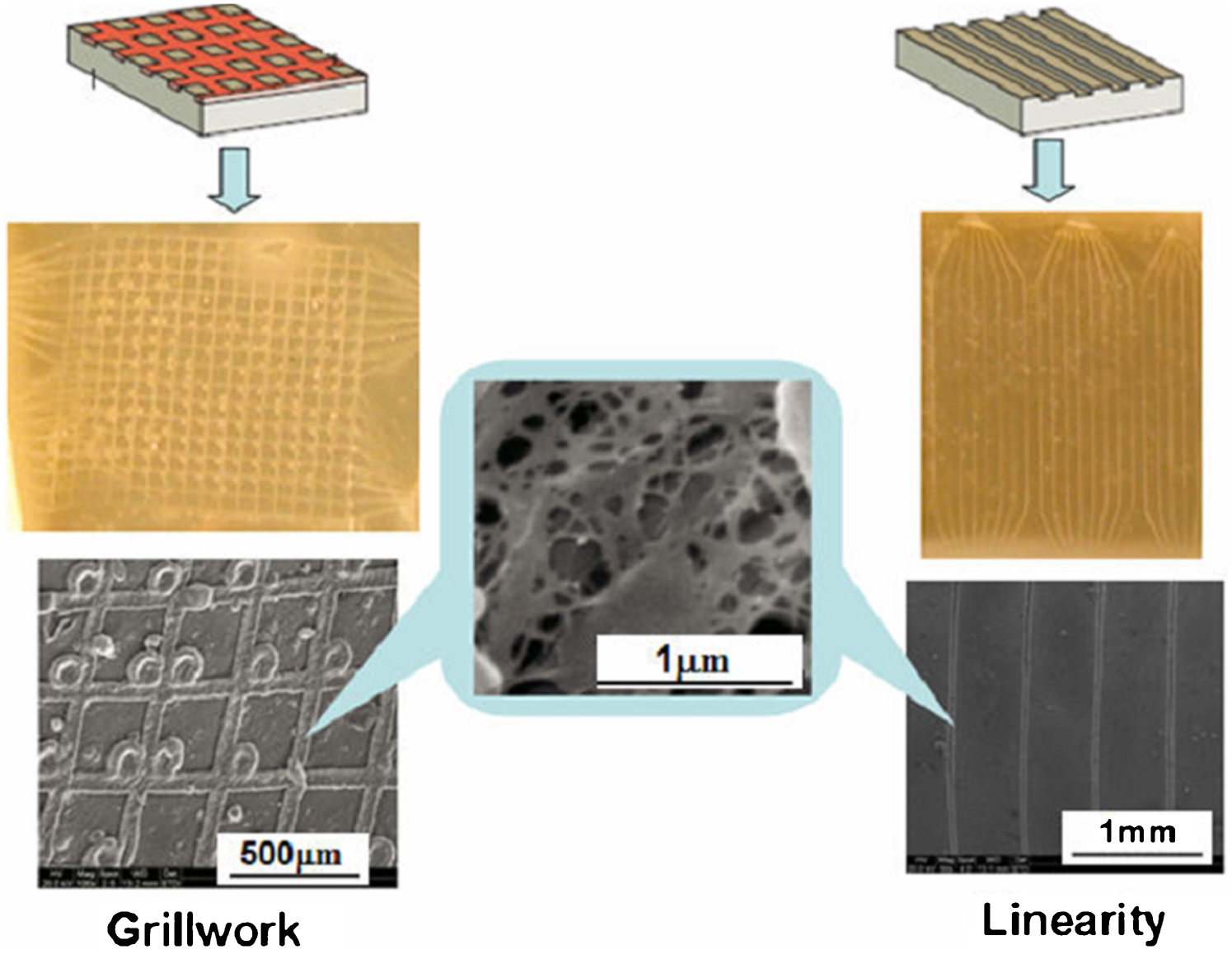
Optical and SEM images of patterned bacterial cellulose fibres in both a grid and a linear array pattern using microfluidic directed assembly techniques 31
Chitin and chitosan
Chitin, or poly(1→4)-2-acetamido-2-deoxy-β-
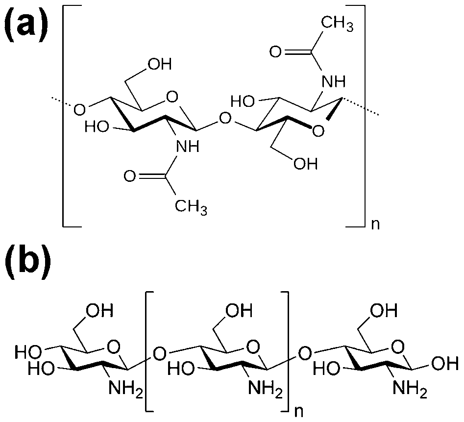
Chemical structure of a chitin and b chitosan 32
Chitin and chitosan fibres are typically made by wet spinning, 32 in which fibres are produced by dissolving the polymer in a solvent and then extruding the solution via fine holes into a non-solvent. The precipitate is in the form of a filament, which can be washed, drawn and dried to form fibres. Dissolution of chitin has proven difficult, but can be achieved with dimethylacetamide (DMAc) or N-methyl-2-pyrrolidone and lithium chloride. 32 Dissolution is greatly improved by treatment of chitin with p-toluene sulfonic acid in i-propanol. 33 The viscosity of the polymer solution can be controlled via the chitin pretreatment (up to 2 h showed added effects), LiCl concentration (optimum 5–9%), chitin concentration (optimum spinnable solution with 5–9% chitin) and temperature. Chitin purified from red crabs was made into fibres by Nakajima et al. 34 via dissolution in an amide–LiCl system. Filaments of 5 μm diameter were spun from a spinneret of 0·05 mm diameter, using a butyl alcohol coagulant. The resulting fibres had demonstrated a tensile strength of 490 MPa. Chitin fibres of 20–80 μm diameter were made by Agboh 33 via extrusion through 50–150 μm diameter holes directly into a coagulation bath, or via extrusion through spinnerets with 150–400 μm diameter into an air gap before introduction into the coagulation bath. Coagulants used included 75 : 25 DMAc/H2O at 40–75°C or methanol at room temperature. Chitosan is a more easily soluble polymer than chitin. Fibres have been made by dissolving chitosan (2–4%) in aqueous acetic acid (0·5–1%) and extruding into 5% NaOH, 35 Na2SO4 with NaOH, 36 2% Na lauryl sulphate, 37 or CuSO4–NH4OH or CuSO4–H2SO4. 38 In the latter case, the fibres were a copper–chitosan complex, but the copper was removable afterward.
Natural chitin exists in three crystal structures: α, β and γ. 32,39 The structural differences between these polymorphs lead to differences in mechanical behaviour, as outlined in Table 1. Chitin fibres can also be made in highly oriented structures when stretched via dry-jet wet-spinning, 32 or other stretching processes. The mechanical properties of chitin fibres are determined by the synthesis conditions and spinning techniques utilized. 32 The dry strength of chitin fibres has been shown to increase with acetylation. 36 Fibre wet strength showed an initial decrease, followed by subsequent increase upon further acetylation. 36 This can be explained because the acetamide groups form hydrogen bonds, causing the crystallinity and strength of inter-chain forces in chitin to increase. 32
Alginate
Alginate, a natural polysaccharide, is extracted from brown seaweeds by treatment with aqueous alkali solutions, such as NaOH. During this process, the salt form of natural alginate is converted to water-soluble sodium alginate,
40
which can be precipitated by addition of calcium chloride. Water-soluble sodium alginate powder can be produced following purification.
41
Alginate is a block copolymer composed of 1,4-linked β-
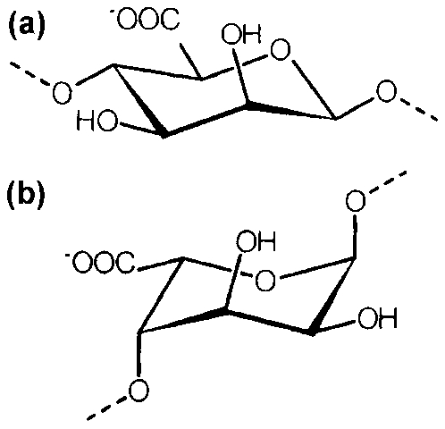
Chemical structures of a β-
Types of blocks that make up alginate polymer chains 42
To make alginate fibres, sodium alginate is first dissolved in water. Solution viscosity can be controlled by varying concentration and molecular weight. To form filaments by extrusion through spinneret holes, viscosities in the range of 10 000–20 000 mPa are needed. 42 This can be achieved with high concentrations of low molecular weight or low concentrations of high molecular weight. To balance production efficiency with fibre strength, viscosities of 40–100 mPa·in 1% solution are ideal. 44 Wet-spinning processes typically use spinning solutions with 5–6% sodium alginate. 42 Variations in temperature (depolymerization at T>50°C for several hours) and pH (unaffected in pH range from 5 to 11) can also affect the solution viscosity and must be controlled during synthesis. 42 Extrusion of sodium alginate solution through spinneret holes into a calcium chloride bath results in water insoluble calcium alginate fibres. Calcium ions coordinate and pack within interstices between buckled guluronic acid units, resulting in a firm gel structure. 45 Gelation time varies linearly with alginate concentration, increases notably with fibre radius and is inversely proportional to calcium concentration. 46 There is no relationship between gelation time and G/M ratios. 46 Extrusion into a methanol, ethanol, isopropanol, or acetone coagulation bath will result in sodium alginate fibres, but these are of lower tenacity than calcium alginate fibres. 44 For wound healing applications, it is desirable to produce calcium sodium alginate fibres, because the calcium ions provide integrity to the wet fibres, while the sodium ions provide absorbency. To produce these fibres, calcium alginate fibres are washed with HCl to replace some calcium ions with hydrogen ions, which are subsequently replaced with sodium ions by treatment with sodium carbonate or sodium hydroxide. 47 The ratio of calcium to sodium ions can be tailored to specifically engineer the desired gel swelling and absorbencies.
Collagen
Collagen is a rather stiff and hard protein with several levels of hierarchy, as depicted in Fig. 6. Tropocollagen molecules, which have lengths of ∼280 nm and diameters of ∼1·5 nm, 48 comprise three polypeptide strands (alpha chains), each with the conformation of a left-handed helix with approximately 0·87 nm per turn. 39,49 The amino acid sequence in each alpha chain varies with collagen type. 39 Three left-handed helices are twisted together into a right-handed triple helix, a cooperative quaternary structure stabilized by numerous hydrogen bonds. 50 Each triple-helix associates into a right-handed super–super–coil referred to as the collagen microfibril. Microfibrils, in turn, arrange themselves into fibrils, which are organized into fibres, or bundles of fibrils with diameters between 0·2 and 12 μm. 39 In some tissues, the fibres organize themselves into more complex patterns, leading to two- and three-dimensional networks. Aside from amino acid sequence, other distinctions between the collagen types are due to variations in length of non-helical fraction, helix length and the number and nature of carbohydrate attachments. 39,50 Collagen in skin, tendon and bone is mostly type I, whereas type II makes up cartilage and type III is a major constituent of blood vessel walls. 50
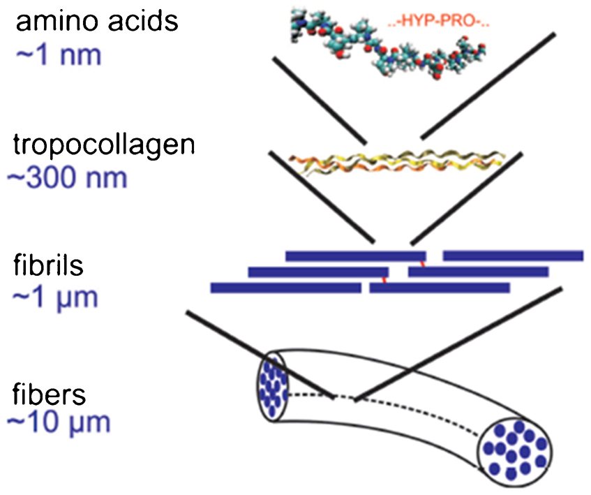
Schematic illustrating the structural features of collagen, which range from the amino acid sequence to collagen fibres with lengths of ∼10 μm 48
Collagen can be extracted from tissue using two different methods – one resulting in molecular collagen and the other resulting in fibrillar collagen. 51 Isolation of molecular collagen requires cleavage of the non-triple helical telopeptides of collagen molecules via use of a proteolytic enzyme, such as pepsin. 52 This process renders the collagen molecules soluble in an aqueous solution, because it is the telopeptides that form intermolecular cross-links in vivo. The resulting molecular collagen is called soluble collagen or atelocollagen. These molecules can be reconstituted into various polymorphs of collagen, but the packing is not as efficient as with intact molecules because the telopeptides facilitate fibril formation. 53 Repetitive precipitation of the pepsin-solubilized collagen with a neutral salt results in purification. 51
Isolation of fibrous collagen involves sequential removal of non-collagenous material from the tissue. 51 Salt extraction removes non-collagenous moieties that are soluble in aqueous conditions and also collagen molecules that have not yet been covalently integrated into the fibrils. Low molecular weight solvents are used to extract lipids, and acids are used to extract acidic proteins and glycosaminoglycans (GAGs) upon weakening of interactions between these species and collagen fibrils. Interactions between basic proteins and collagen fibrils are facilitated by alkaline extraction. Glycoproteins, proteoglycans (PGs) and elastins can be removed from tissue with enzymes such as collagenase. This sequential process results in an insoluble, intact collagen matrix, called insoluble collagen or fibrillar collagen.
The complex structure of natural fibres dictates their mechanical behaviour. For example, the structure of collagen fibres in vivo (e.g. in tendons) is characterized by waviness with a spatial period 2l
0 and the angle θ0.
39
This wavy structure plays an important role in deformation; under tensile stress the bent fibres stretch out, and when the load is removed the waviness returns. When stretched beyond the straightening of the waviness, damage begins to occur. As can be seen in Fig. 7, the deformation of collagen occurs in three distinct stages. The first region, known as the Toe Region, is where the tendon operates under normal physiological conditions. The maximum permissible strain that a collagen molecule can experience without damage can be calculated according to:
39
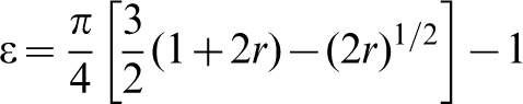
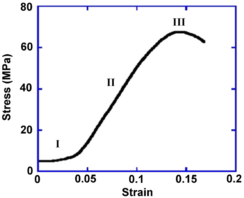
Stress–strain curve of tendon collagen exhibiting three characteristic stages of deformation: I, toe; II, linear; and III, failure 39
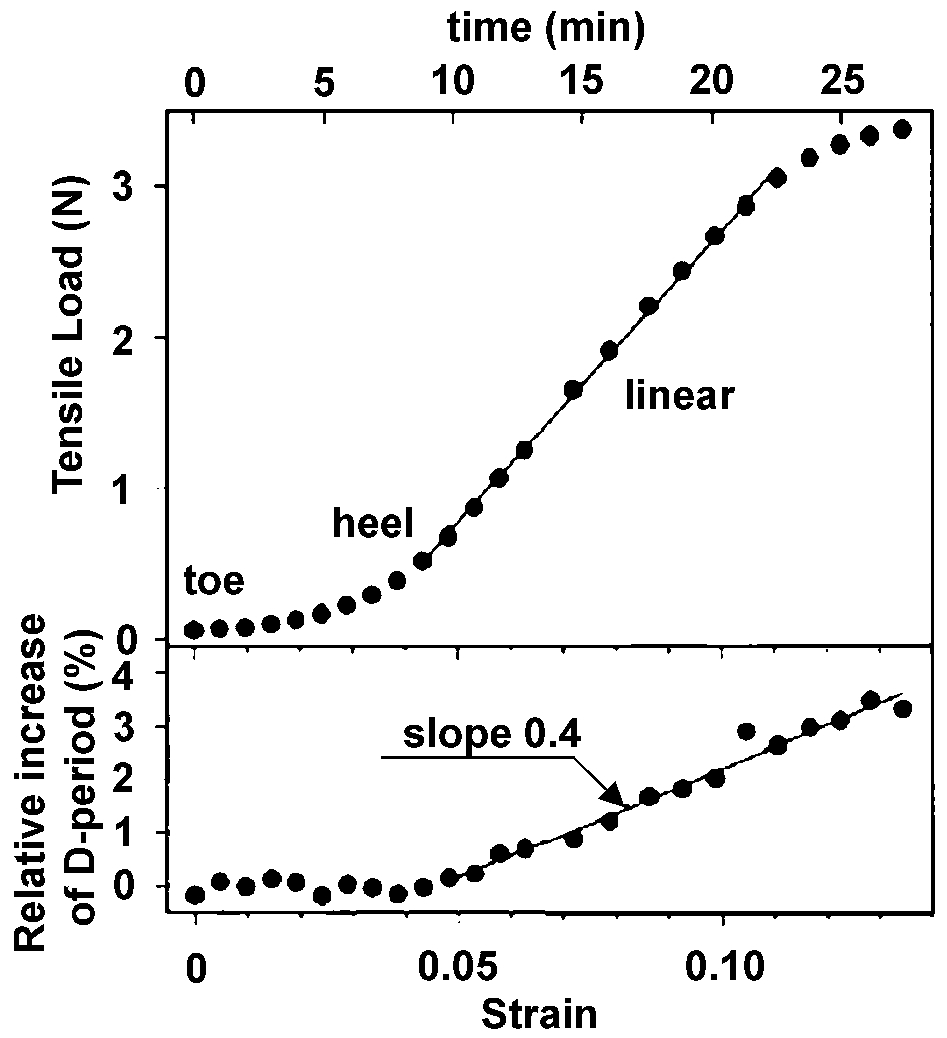
Tensile load and corresponding increase in D-period of rat tail collagen during tensile loading combined with synchrotron X-ray scattering 54
Spider silk
Silks, in general, exhibit interesting properties. In particular, spider silks are remarkable because of their mechanical properties, including a unique combination of tensile strength and extensibility. Its toughness exceeds that of steel and Kevlar. Many different types of spider silk exist, with structures and compositions that vary with their specific functionality related to catching prey. The two most important varieties of spider silks are the major ampullate silk, which composes the frame and radii of spider webs, and flagelliform silk, which composes the capture spiral of webs. 55,56 Proteins produced in the major ampullate silk gland have a molecular weight of >300 kDa, diameters from 1 to 20 μm (depending on species) and a core–shell type structure, as illustrated in Fig. 9. 56,57 Spidroins, the two structural proteins in the core, are composed mostly of glycine, alanine and proline, as depicted in Fig. 10. The spidroins resemble block copolymers containing blocks of polyalanine that form β-sheet stacks, and either (GGX) n blocks (where X is tyrosine, leucine, or glutamine), which form 310-helices, or GPGXX blocks, which form β-turn spirals. 56 The β-sheet stacks provide high tensile strength, whereas the turn spirals provide elasticity. The extremely high tensile strength (similar to Kevlar) and moderate elasticity make these silks ideal for use as the scaffold upon which other silks are attached during web construction and as a lifeline for escape in the event of a predator attack. Flagelliform silks, on the other hand, have a molecular weight of ∼500 kDa, are highly elastic, are composed of only one major protein containing greater amounts of proline and valine and less alanine. 56 Flagelliform silks also are composed of (GGX) n and GPGXX blocks as well as a polar hydrophilic spacer, which may be important for cross-linking and hydration. 58
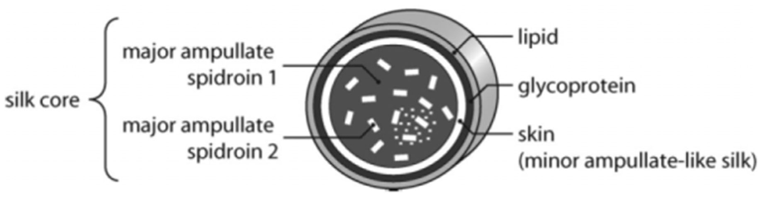
Schematic of a cross-section of major ampullate silk fibre 56
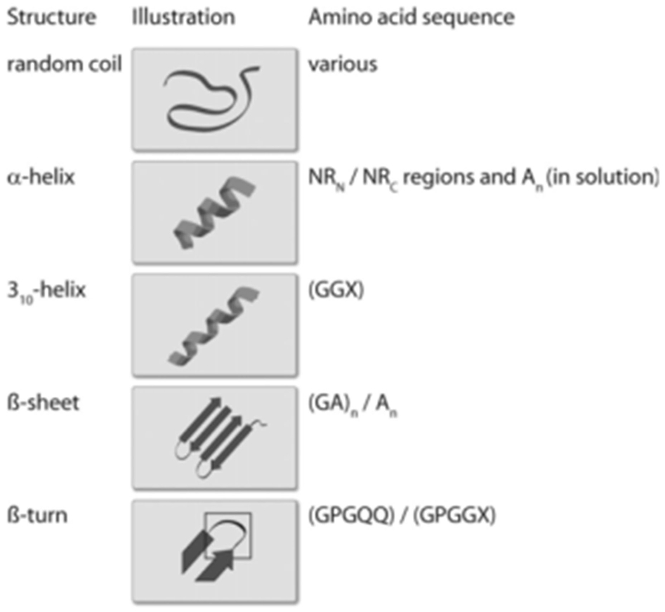
The repetitive blocks of amino acids that make up the common secondary structural patterns in spider silk proteins 56
Spider silk proteins can be synthesized in the laboratory using E. coli (HMS174(DE3) K-12 derivatives) as host cells via a process of high density fermentation and subsequent purification. 56,59 Although naturally occurring spider silks are insoluble in water, recombinantly produced proteins with identical primary amino acid sequences exhibit varying solubilities, enabling versatility in solvent choice and therefore the ability to process these proteins into fibres, films, foams, spheres, hydrogels and capsules. 56,60 The resulting structures and functions of the obtained materials are directly controlled by the content and distribution of crystalline β-sheets, a process that can be controlled by the mode of processing and environmental factors including solvent, pH, water and concentration of protein and salt. 61 Natural spider silk fibre production utilizes processes of ion exchange, water extraction, acidification and exposure to mechanical forces. To mimic these processes in the lab, potassium phosphate has been added to the synthesized proteins, and then hand-drawing was applied to subject the solution to shear forces. This resulted in production of smooth, β-sheet rich fibres. 62 Spider silk fibres have also been formed by electrospinning. 63 Spin dopes prepared by dialyzing genetically engineered silk (MaSpI protein analogues) in urea containing Tris buffer and salts yielded fibres of 10–60 μm diameter with molecular orientation and mechanical properties similar to those of natural spider silk. 64 Spin dopes derived from ADF-3 recombinant spider-silk protein yielded fibre diameters up to 40 μm with fibre toughness and modulus comparable to native dragline silks, but lower tenacity. 65 Fibres with an average diameter of 300 nm were generated from Nephila clavipes MaSpI silk dope prepared in hexafluoroisopropanol, and control of conformation was achieved; results indicated that molecular alignment might be possible, potentially offering improved fibre properties. 66
By adding methanol to recombinant forms of the dragline silk protein ADF-4, the silk has been shown to self-assemble into nanofibres with diameters of ∼3 nm and lengths less than 1 μm. 63 Over the course of a few days, these nanofibres transformed into a hydrogel fibre network. These hydrogels exhibited a nonlinear viscoelastic material response with low stiffness and strength. Cross-linking was induced by visible light after applying ammonium peroxodisulfate and tris(2,20-bipyridyl) dichlororuthenium(II) to the surface of the hydrogel. In another approach, addition of sodium phosphate to aqueous solutions of engineered spidroins was shown to induce their self-assembly into β-sheet rich nanofibrils 67 that hierarchically assemble into a sample spanning network that ultimately immobilizes the solvating water, yielding a hydrogel. 56
Mechanical properties of natural and synthetic fibres are compared in Table 3. Natural fibres have a wide range of mechanical properties as would be expected after many years of being optimized by nature for their specific application. For example, the spider major ampullate silk exhibits significantly higher stiffness and strength than the viscid silk, but the two silks have nearly identical toughness due to the differences in extensibility required for their function (Fig. 11). The range in mechanical properties and deformation mechanisms available in natural fibres offer great potential for incorporation into hydrogels for various applications. Note that for applications requiring significant energy absorption, natural fibres exhibit significantly higher toughness (although lower strength) compared with traditional engineering materials of comparable density. Combination of natural and synthetic fibres into hydrogel composites could lead to materials with previously unattained mechanical properties.
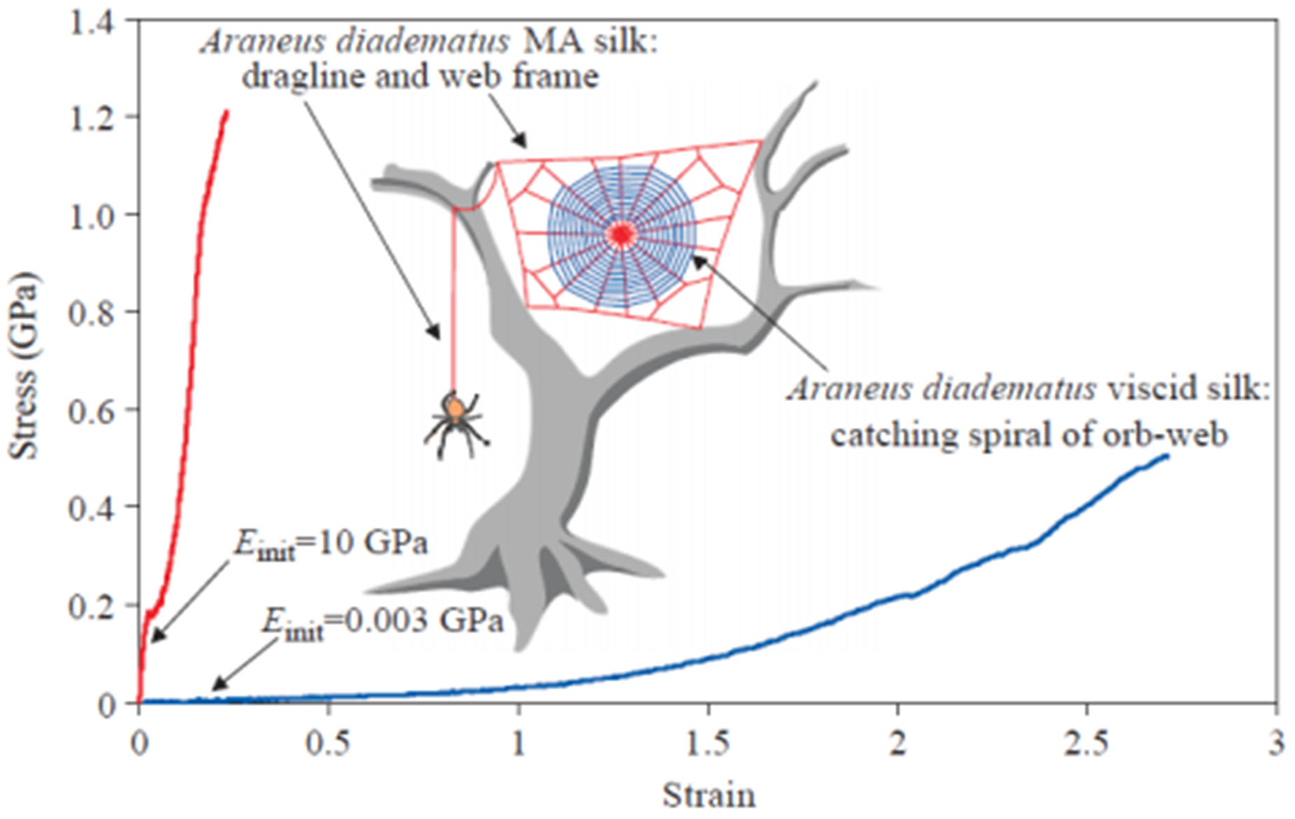
Stress–strain curves for major ampullate gland silk (red line) and viscid silks (blue line) from the spider Araneus diadematus; E init indicates initial stiffness 71
Synthetic fibres
Synthetic fibres consist of man-made fibres from raw materials that are processed into micro- or nanofibre form, either in small scale processes or large scale parallel processes. Polymer fibres are made from materials such as polyamides, polyesters, polyvinyls, acrylics and polyaramids. Glass fibres are made from silicon oxide and blends of other oxides such as barium oxide, aluminium oxide and many other metal oxides. Crystalline ceramic fibres are a final class of synthetic fibres comprised of materials such as aluminium oxide and silicon carbide. While synthetic fibres have become relevant in many different markets of the world economy, their use to date in hydrogel systems as reinforcements has been limited. As described below, exciting new research in synthetic nanofibre fabrication and property evaluation lends significant promise for utility as reinforcing elements in new transparent hydrogel systems.
Polymer fibres
Polymer fibres are one type of synthetic fibre. The polymers are normally produced from petroleum based chemicals through chemical processing. There are many different types of polymer fibres having a wide range of mechanical and optical properties of interest for consideration as hydrogel reinforcement elements. In particular, polymer nanofibres are quite appealing for a transparent hydrogel reinforcement, because their size can be controlled to be less than the wavelength of visible light and their composition and surface chemistry tailored to achieve a suitable distribution within the hydrogel matrix. The most common classes of polymers include polyamides, polyesters, polyvinyls, polyolefins, acrylics and aramids. The following sections discuss the different classes of synthetic polymer nanofibres.
Polyamide fibres
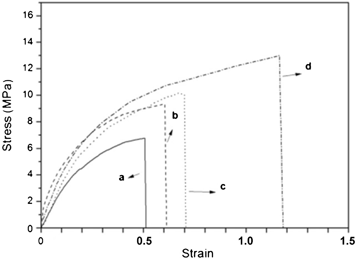
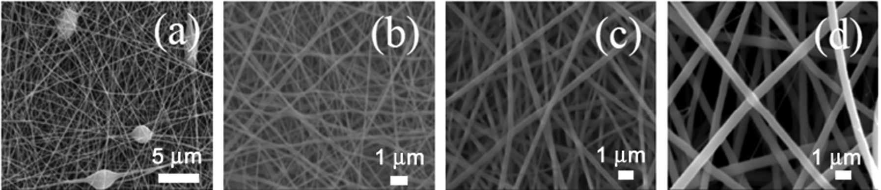
Nylon 6 and Nylon 6,6 are two very common polyamide fibres commercially produced. Their chemical structures are shown in Fig. 12. One of the principal methods of producing Nylon nanofibres is via the electrospinning process, as shown in Fig. 13a . In this case, the Nylon is typically dissolved in a solvent such as a formic acid/acetic acid solution and then electrospun. By adjusting the electrospinning parameters (e.g. voltage, collector–syringe distance, solution concentration and constituents), it is possible to control the fibre morphology and the resultant mechanical properties. For example, Pant et al. 72 were able to systematically vary the modulus, ultimate tensile strength and strain to failure by using a formic acid solution to reduce the molecular weight of some of the dissolved Nylon chains by combining it with fresh solutions of Nylon to electrospin micro–nano Nylon fibrous mats. 72 Figure 13 shows the resultant morphology for four permutations. As the concentration of degraded Nylon increases, one notices an increase of smaller diameter fibres present in the micrographs. In Fig. 13d, a spider web-like network of Nylon nanofibres is present between the mat of ∼500 nm and 1 μm diameter fibres. The mechanical properties changed drastically with the appearance of the smaller nanofibres, as indicated by the stress–strain curves of Fig. 14. The tensile mechanical properties derived from Fig. 14 are shown in Table 4. The nanofibres have a much higher specific surface area compared with the microfibres and may also have relatively fewer defects within the fibre, which likely result in the improved mechanical properties reported in Table 4.
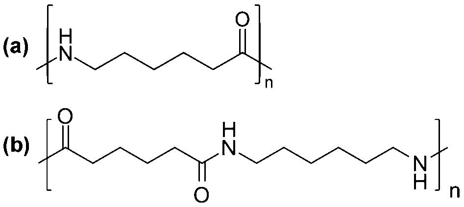
a Structure of Nylon 6 and b structure of Nylon 6,6
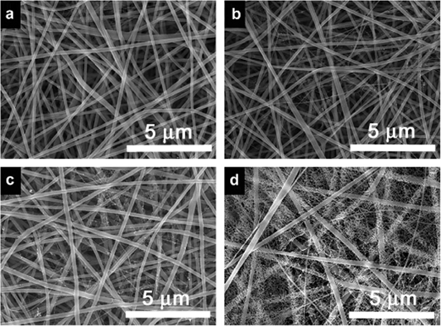
FE-SEM images of electrospun Nylon 6 nanofibrous mats containing a 0, b 5, c 10 and d 20 wt-% of solvent-degraded solution in freshly prepared solution 72
a 0, b 5, c 10 and d 20 wt-% degraded Nylon 6 solutions in freshly prepared solution 72
Tensile strength, Young’s modulus and strain at break of Nylon 6 mats containing different fractions of solvent-degraded polymer solution 72
Bazbouz and Stylios 73 tested the mechanical properties of single Nylon 6 nanofibres as opposed to a whole mat as described for the Pant et al. research cited earlier. Figure 15 shows one of the experimental methods used by Bazbouz and Stylios to test the individual Nylon nanofibres, and Fig. 16 shows an example of the resultant stress–strain curve for a single 800 nm diameter Nylon 6 nanofibre. From the data in Fig. 16, the mechanical properties of a single Nylon 6 nanofibre are: Young’s modulus of 901·65 MPa, tensile strength of 304 MPa, yield stress of 136·9 MPa, yield strain of 15% and strain at break of 40%.
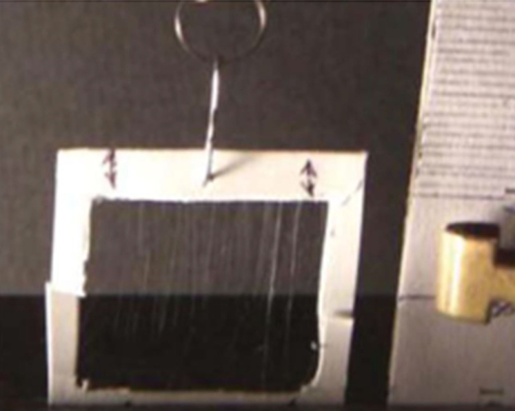
Individually aligned nanofibres are visible by light scattering. They are gripped between the spring and the fixed head through the cut cardboard frame. Non-required nanofibres were removed to prepare an electrospun single nanofibre for tensile testing 73
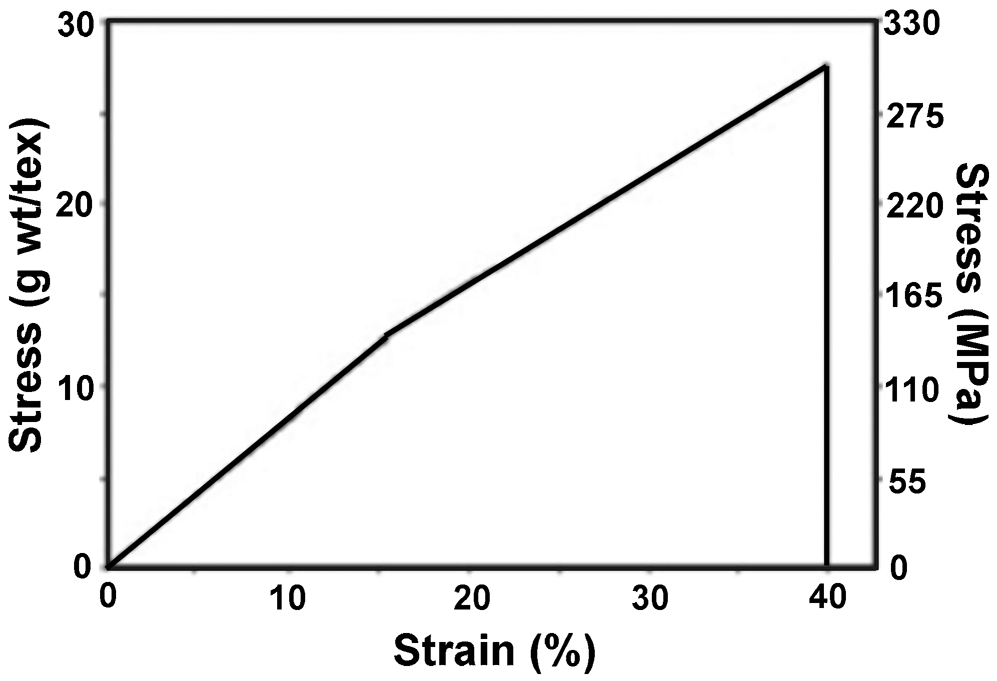
Average stress–strain curve of a single electrospun Nylon 6 nanofibre 73
Polyester fibres
A pure polyester, poly(ethylene terephthalate) (PET), nanofibre and a polyester block copolymer, poly(hexamethylene adipate)–PEO (PHA–b–PEO), nanofibre are good examples of polyester nanofibres that have practical application in the areas of filtration, medicine, pharmacy and agriculture. Their chemical structures are shown in Fig. 17.
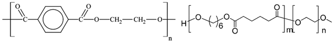
PET mer (left) and PHA-b-PEO mer (right)
PET is a common polymer that has been widely used in textiles. Nanofibre mat morphologies of PET have been used as filtration membranes for juice purification. 74 A hybrid PET–chitosan nanofibre mat showed improved anti-microbial activity compared with the PET nanofibre control and also showed better fibroblast compatibility. 74 Duzyer et al. 74 focused on the thermo-mechanical and structural properties of native PET nanofibres produced via electrospinning and the impact of various electrospinning parameters on the resultant properties. One parameter varied was the solution concentration (their electrospinning method was the solvent spinning method as described below in Synthesis of natural and synthetic fibres section). The diameter distributions and the measured tensile mechanical properties are shown in Table 5. One can see that the 13 and 16 wt-% solutions yielded nanofibres that were just submicrometre, on average. Wang et al. also adopted a similar method and studied the impact of PET molecular weight and polymer concentration on the resultant nanofibre morphology as shown in Fig. 18. The figure shows the enhanced fibre size homogeneity with increasing concentration of PET. 75
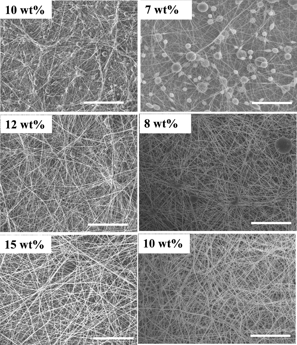
The scale bar is 50 μm. 75
Diameter distributions and mechanical properties of the polyester nanofibres as a function of PET concentration 74
Sun et al. 76 focused their efforts on developing a ‘green electrospinning’ process to yield nanofibres of a biodegradable aliphatic polyester compared to other biodegradable polymers such as poly(E-caprolactone) (PCL) and polylactic acid (PLA), which can be electrospun only using solutions containing harmful organic solvents. The synthesis process involved the following basic steps: polyester synthesis (melt polycondensation), suspension preparation (dissolution in acetone, addition of water and surfactant, evaporation of acetone), suspension concentration using dialysis and electrospinning. The resultant nanofibrous mat and fibre morphology are shown in Fig. 19. The figure shows a randomly oriented mat with fibres that are about 350–550 nm in diameter for the 4% PEO variety of PHA-b-PEO. The fibres are water stable after two days with only a slight increase in surface roughness, making them suitable for biological applications requiring uniformity and smoothness.
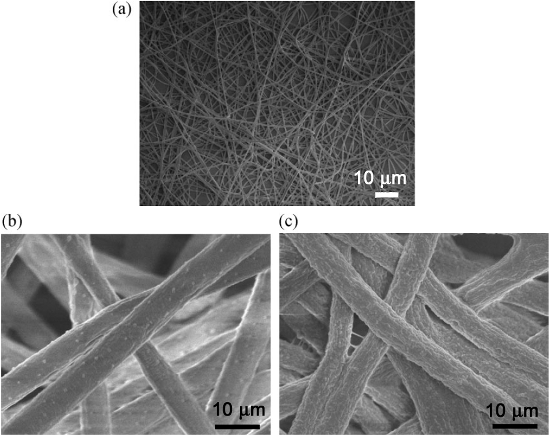
a SEM at 1000× of the 4% PEO PHA-b-PEO nanofibres, b zoom image at 20 000× of 4% PEO PHA-b-PEO nanofibres before water treatment and c the same as b but after water treatment for 2 days at room temperature 76
Polyvinyl fibres
One polyvinyl family fibre that has been studied in great detail is polyvinyl alcohol (PVA). The structure of PVA is shown in Fig. 20. These fibres have many uses, such as reinforcement fibre in concrete.
Chemical structure of PVA
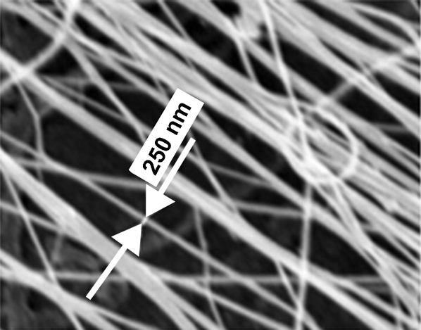
When comparing the surface area between a film of a material and a nanofibrous mat of the same material, the nanofibrous mat has a very large relative surface area. Therefore, potential medical applications for transdermal patches consisting of drug loaded nanofibre mats exist. Toward that end, Ngawhirunpat et al. 77 studied the fabrication of capsaicin (CC)-loaded PVA nanofibre mats and compared their CC release properties to those of PVA films. During their electrospinning fabrication process, they examined the morphology of the as-spun PVA fibre mats that were loaded with CC as shown in Fig. 21. The average diameter of the fibres was in the 165 nm range (in the collected electrospun mat). Ngawhirunpat et al. also examined the tensile mechanical properties of the PVA fibre mats and films and found the average mat tensile strength to be 16·5 MPa and the as-cast films strength to be 20·7 MPa. 77
Scanning electron micrographs of as-spun PVA fibre mats from 10% w/v PVA solutions loaded with CC at 0·05% by weight of PVA 77
Most electrospun nanofibres have random orientations of fibres in the mat, similar to the mat shown in Fig. 21. However, some researchers have achieved uniaxial alignment by electrostatic repulsion induced self-assembly. Yan et al. 78 have taken electrospinning self-assembly to the next level by developing the capability to self-assemble electrospun nanofibres into honeycomb-patterned nanofibrous structures (HNFSs). The authors have identified a range of experimental conditions over which PVA self-assembles into the structures shown in Fig. 22. For PVA, the pore size is ∼130–250 μm and the depth is over 150 μm. The porous structures could find end application as templates to synthesize other HNFSs such as oxides. The novel structures may also find use as tissue engineering scaffolds, catalyst supports, filters, sensors, micro-containers, battery electrodes and many other application areas. The authors attribute the unique microstructures to the delicate balance between surface tension and electrostatic repulsion forces.
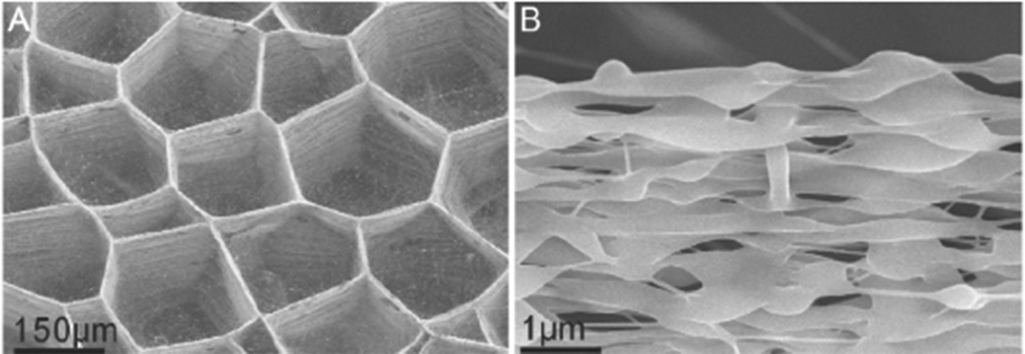
SEM images of PVA HFNSs produced by electrospinning 78
Polyolefin fibres
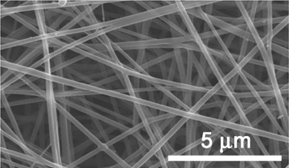
Polyethylene and, in particular, ultra-high molecular weight polyethylene (UHMWPE) fibres are of keen interest for many applications because of their unique combination of chemical and physical properties, which include high strength, abrasion resistance, impact resistance, good dielectric properties, as well as approval for use in food and biomedical applications. The fibres have traditionally been prepared by gel spinning technology relying on a series of draws that resulted in strengths of 1·5 GPa and an as-prepared modulus of 140 GPa. 79 Rein et al. 79 have tried to simplify the fabrication process by developing a simple one-step electrospinning fabrication method for UHMWPE nanofibrous mats. The morphology of the resultant nanofibres is shown in Fig. 23. In the studied parameter space, the fibres were a minimum of about 250 nm in diameter. The mechanical properties for a 65 μm diameter yarn of the UHMWPE nanofibres included a strength of about 129 MPa, an initial elastic modulus of 390 MPa and a strain to failure of about 33%. 79
SEM image showing UHMWPE nanofibres electrospun from solutions in a 1 : 1 (w/w) mixture of p-xylene and cyclohexanone (CH) at a UHMWPE concentration of 0·025 wt-% 79
Polypropylene (PP) is another important type of polyolefin for many applications such as filter media, biomedical replacement materials, reinforced composite materials and antistatic materials. Prior to about 2007 it had been extremely difficult or impossible to fabricate fine, uniform filaments (e.g. nanofibre filaments) of PP. All of that changed in 2007 when Wang et al. 80 succeeded in developing a new method to form continuous yarns of nano-sized thermoplastic fibres. Their method is described by the flowchart in Fig. 24. The as-prepared isotactic PP nanofibres produced via the method shown in Fig. 24 are shown in Fig. 25 for hot drawn ratios of 2, 8 and 25. Based on the images in Fig. 25, it appears that there is at least a qualitative reduction in the fibre diameter as hot drawn ratio is increased. By analysing the images quantitatively, Wang et al. were able to produce a diameter histogram for each hot drawn ratio. The data are shown in Fig. 26 and reveal that the diameter distribution has a smaller range and also a smaller mean diameter (∼250–300 nm) for the highest hot drawn ratio PP nanofibre sample.
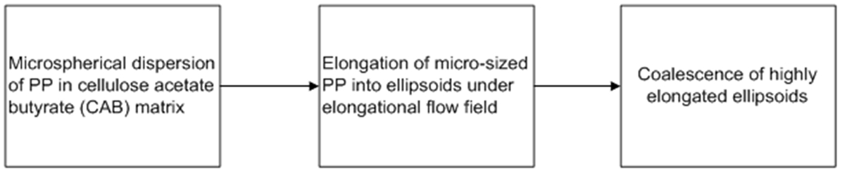
Flowchart describing the novel nano-PP fibre formation process developed by Wang et al. 80
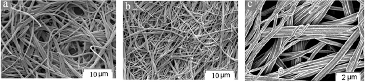
SEM images of iPP nanofibres from the CAB/iPP = 90/10 blends with hot drawn ratios of a 2, b 8 and c 25 80
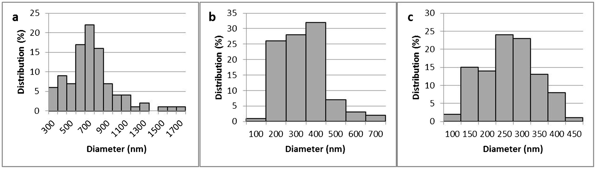
Diameter distributions of iPP nanofibres prepared by removing the CAB matrix of CAB/iPP = 90 : 10 with three hot drawn ratios. a Hot drawn ratio = 2 (bar width = 200 nm); b Hot drawn ratio = 8 (Bar width = 100 nm); c Hot drawn ratio = 25 (Bar width = 50 nm)
Acrylic fibres
Poly(methyl methacrylate) (PMMA) is a very common acrylic polymer that is used for optical applications because it is clear in the visible spectrum and shatter resistant in comparison with glass. It is also used in various medical technologies and human implants. The chemical structure of PMMA is shown in Fig. 27. Because of its blend of optical properties, good mechanical properties and cost advantage compared to polycarbonate, Carrizales et al. 81 undertook a detailed study of the morphological and mechanical properties of electrospun PMMA nanofibres in mat form. The as-prepared PMMA nanofibres are shown in Fig. 28, and have an average diameter of 543±140 nm (as measured at the locations indicated in Fig. 28). 81 The tensile mechanical properties of the PMMA nanofibres are given in Table 6, and provide a suitable baseline for future research in this area.
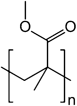
Chemical repeat unit of PMMA
SEM of electrospun PMMA 81
Tensile mechanical properties of PMMA nanofibre mats 81
Functionalized PMMA nanofibres have also been developed with interesting properties/capabilities related to embedding fragrances and flavours into the fibres. For example, Uyar et al. 82 developed electrospun PMMA with cyclodextrin–menthol inclusion complexes. Cyclodextrins (CD) have been proven useful for stabilizing flavour/fragrance ingredients in the food, cosmetics and textile fields. The utility of CDs is derived from their toroidal structure, akin to crown ether molecules. Similar to crown ethers’ capability for binding cations or molecules with great size related specificity, the CDs can also stabilize molecules with particular size, conformation and charge. The chemical structures and general dimensions for γ, β and α CDs are shown in Fig. 29. Compared with electrospinning neat PMMA with menthol, the PMMA with CD-menthol produced nanofibre mats with reduced nanofibre diameters, as shown in Fig. 30.
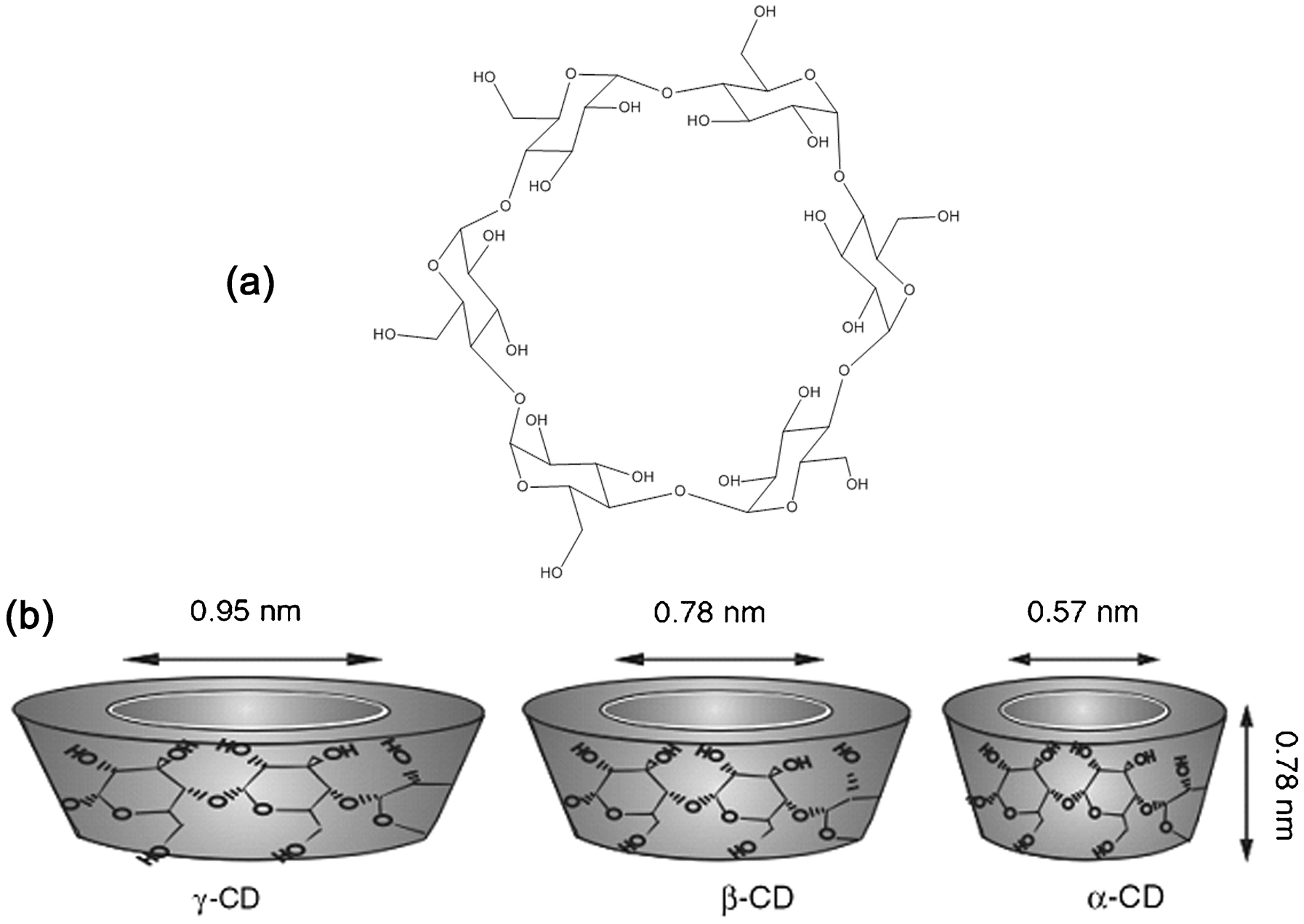
a The chemical structure of cyclodextrin showing the functional groups; b, c and d dimensions of γ, β and α CDs, respectively 82
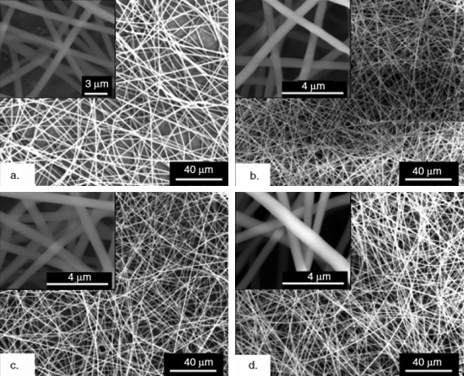
SEM images of electrospun nanofibres of a PMMA/menthol, b PMMA/α-CD-menthol-IC, c PMMA/β-CD-menthol-IC and d PMMA/γ -CD-menthol-IC. Insets show higher magnification images 82
Polyaramid fibres
While cellulosic media are used traditionally for filtration applications, polyaramid fibre mats provide a good non-woven high temperature option for filtration. One form of aramid polymer, termed meta-aramid due to its chemical structure (Fig. 31), has recently been successfully prepared in nanofibre mat form via electrospinning from a solvent system. Yao and Kim 83 used a LiCl/DMAc solvent to electrospin meta-aramid nanofibres. The size and shape of the electrospun meta-aramid fibres are shown in Fig. 32. In all of the studied concentrations of aramid in the solvent system, the resultant fibres are sub-500 nm in diameter. The relationship between aramid concentration and resultant fibre diameter was also investigated (Fig. 33). The approximate tensile modulus for a meta-aramid nanofibre mat produced via electrospinning from an 11 wt-% aramid solvent was 370 MPa as determined through analysis of Yao and Kim’s reported stress–strain curve. The ultimate tensile strength was about 15 MPa and the strain to failure was approximately 13%.
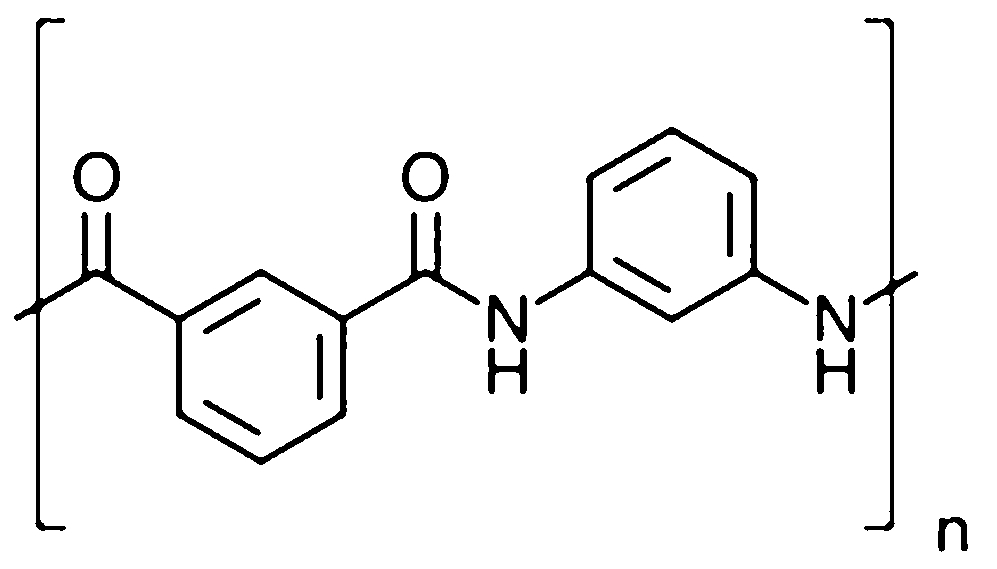
Structural repeat unit of poly(meta-aramid)
a 8·5 wt-%; b 9 wt-%; c 11 wt-%; d 13 wt-% 83
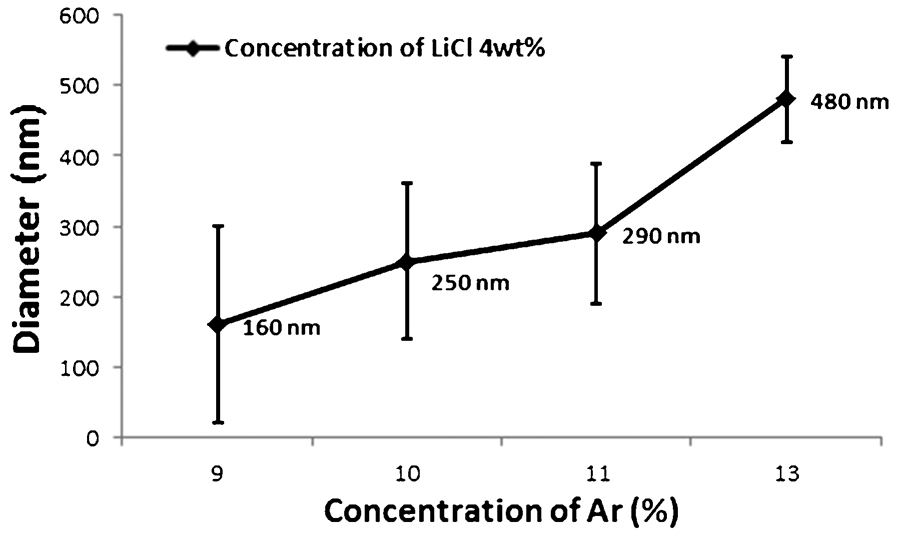
Dependence of fibre diameter on concentration of aramid in the electrospinning solvent system 83
Glass fibres
Glass fibres have long been utilized to improve the mechanical properties of polymers through the design and fabrication of composites. As one can see from Table 7, the tensile strength and modulus of glass fibres are very high compared with those of natural fibres, and the low cost of glass compared with carbon fibres makes them compelling in many applications. The mechanical properties of E-glass and S-glass (two common compositional glass variants for fibre applications), as reported in Table 7, are for traditional diameter glass fibres (e.g. in the diameter range of ∼9–15 μm). While the tensile strength dramatically increases as the diameter of glass fibres decreases below about 12 μm (Fig. 34), the fibreglass manufacturers do not make smaller nanofibres due to human health concerns. However, with careful environmental controls and processing protocols, the health concerns could be mitigated; though, the extra costs ensued by implementing such controls may only permit niche, high value applications.
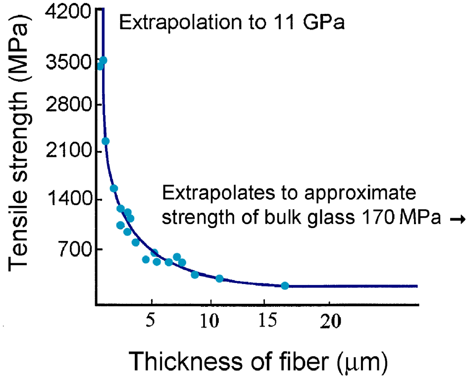
Tensile strength of glass fibres as a function of fibre diameter (Courtesy of K. K. Chawla)
Mechanical properties of natural fibres and glass fibres
Weichold et al. 84 have developed an electrospinning process to generate silica nanofibre mats with filament diameters of 600–1000 nm. The process involves electrospinning a tetraethylorthosilicate precursor followed by subsequent heat treatment at ∼1000–1100°C. The best mechanical properties were observed when the heat treatment was performed at 1065°C. The morphology of the 1065°C treated nanofibre mat is shown in Fig. 35. Weichold et al.’s experiments have shown that non-woven randomly oriented silica nanofibres can be readily synthesized via electrospinning, and the mechanical testing indicated that some limited improvements in tensile performance over neat epoxy could be expected for epoxy reinforced with the silica nanofibre mats, but that the real improvements of up to 200% increase in strength (over the neat epoxy and much higher than the improvement afforded by unidirectional glass fibre reinforcements) would occur during bending and under complex loads. Bending and complex loads are especially important for aerospace applications.
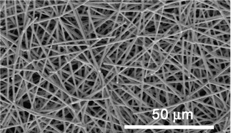
SEM image of the 1065°C treated silica nanofibre mat 84
Crystalline ceramic fibres
Crystalline ceramic fibres are also interesting reinforcements as a result of their improved mechanical properties compared with glass fibres. As with all of the aforementioned fibres described, it is beneficial from an optical transparency perspective to have very small diameter fibres so that an effective medium theory can be used and visible light does not scatter via standard geometrical means at the refractive index gradient locations within the composite material. As an example, transparent alumina (Al2O3) nanofibres have been formed using an electrospinning method at 7–9 kV. 85 The alumina precursor used was aluminium 2,4-pentanedionate in acetone with polyvinylpyrrolidone (PVP) as a polymeric additive. Using a slow ramp rate of 0·5° min–1, the authors were able to maintain the as-spun nano-fibrillar nature of the fibres, as shown in Fig. 36 for fibres heat-treated at 1300°C for 1 h.
Scanning electron micrographs of the Al2O3–PVP composite fibres calcined at 1300°C for 1 h 85
The TEM image shown in Fig. 37 reveals the ∼150 nm diameter Al2O3 nanofibres after 1500°C heat treatment for 1 h. The authors state that the fibres are transparent, but do not differentiate between visual transparency and electron transparency. To determine visual transparency, one may use clear index matching fluids and a light microscope or other optical source. The authors found no evidence of carbon in the spectrum obtained via energy dispersive spectroscopy and no evidence of a D or G carbon peak in the Raman spectrum 86 of the as-fired nanofibres. No mechanical testing or composite synthesis was reported by the authors. However, the alumina nanofibres have potential utility as reinforcements in hydrogel or other composite systems.
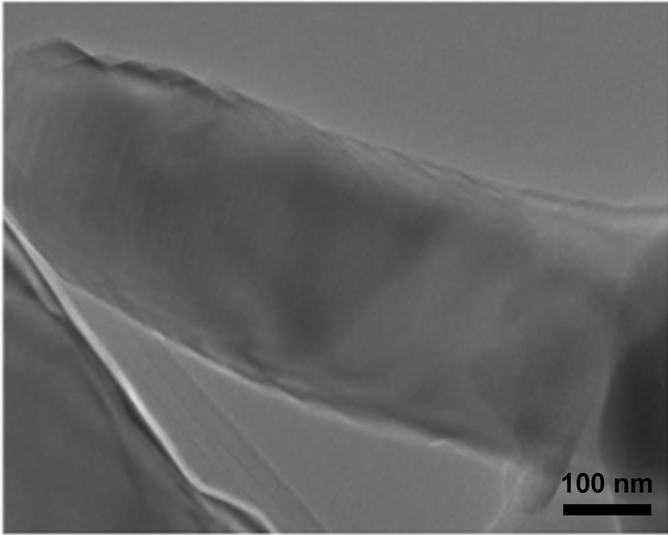
TEM images of the electrospun Al2O3 fibres fired at 1500°C/1 h (bar = 100 nm) 85
Synthesis of natural and synthetic fibres
Synthetic fibres, not found in nature, can be made using a number of techniques, as depicted in Fig. 38. For example, Fig. 38a shows how fibres can be drawn through a coagulation bath following extrusion. 63
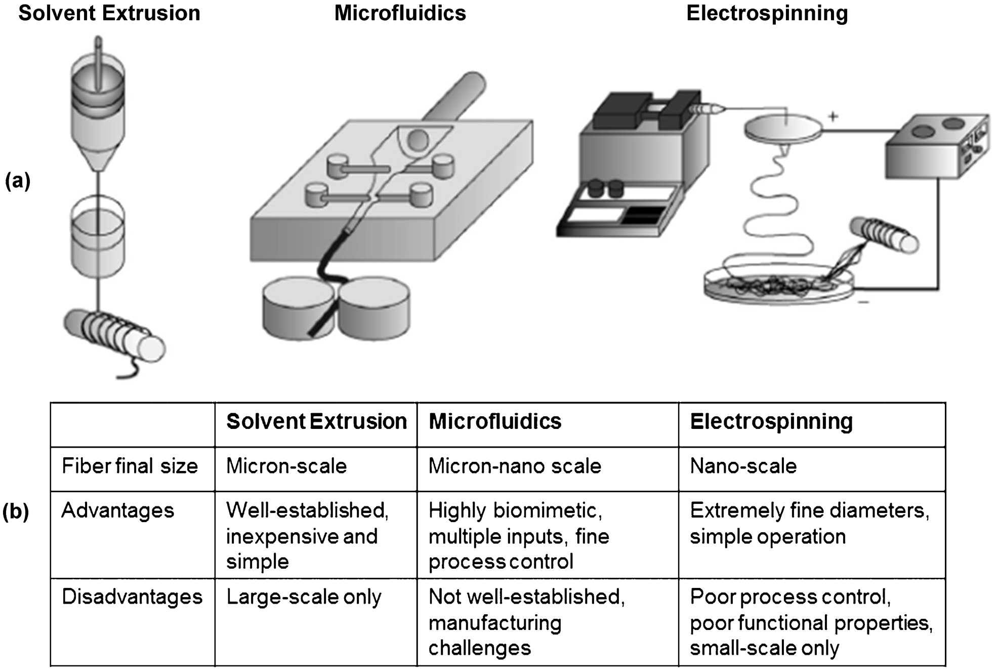
a Solvent extrusion is performed by drawing the fibre through a coagulation bath in a controlled manner. Microfluidic devices use a contracting channel and multiple solvent inputs to regulate the geometry and chemistry of the resulting fibre. Electrospinning processes combine strong voltage gradients and syringe pump extrusion and result in either random or aligned fibre deposition. b Characteristics of the different fibre-forming processes 63
Electrospinning (Fig. 38) is a fabrication process that uses an electric field to control the deposition of polymer fibres onto a target substrate, resulting in mats composed of fibres having diameters ranging from several micrometres down to 100 nm or less. This technique is a rapid and efficient process that can be used to selectively deposit polymers in a random fashion or along a predetermined and defined axis. Electrospinning has been applied to polysaccharides including cellulose, chitin and alginate. 87 It has been demonstrated with collagen fibres that it is possible to tailor subtle mechanical properties into a matrix by controlling fibre orientation. 49 The applied electric field has been shown to induce a certain degree of crystallinity in alginate-based nanofibres, as indicated by the presence of a strong diffraction band at approximately 16°2θ starting alginate powder. 68 The enhanced crystallinity was ascribed to realignment of alginate chains during the electrospinning process, forming a higher degree of molecular order in the material’s structure. Increased crystallinity is favourable for producing fibres with increased mechanical strength and for creating fibrous structures analogous to tissue structures, which contain proteins (e.g. collagen in cartilage) and GAGs exhibiting a certain degree of crystallinity.
Melt spinning (Fig. 39) is a process during which polymer pellets are fed into one end of an extruder. 88 These pellets soften as a result of exposure to heat and shear, and the molten polymer mixture is delivered to the spinneret, that has up to 1000 holes which the polymer is forced through using pressure, thus forming fibres. The extrudate is stretched and solidified and can be further tailored (in terms of diameter, crystallinity, orientation etc.) by varying cooling rate and method, take-up speed and other variables.
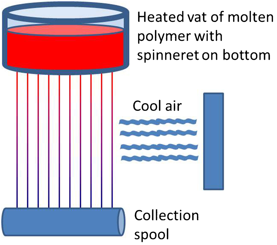
Schematic diagram of a melt-spinning process; note that the extruder is electrically heated
Microfluidics is a simple and cost-effective fabrication procedure that has been used to produce various polymer microstructures, including microfibres. 89,90 This technique is biomimetic 63 and compatible with sensitive biological materials, including enzymes, proteins, drugs and cells, enabling them to be loaded into the microstructures. 90 Figure 40a shows a schematic of microfibre generation via microfluidics and principle of gelation applied to generate alginate fibres. 90 The resulting fibres are shown in Fig. 40b . Controlling the sample and sheath flow rates during microfluidic fibre generation enables control of the resulting microstructure dimensions, as can be seen in Figs. 40c–e . 89,90
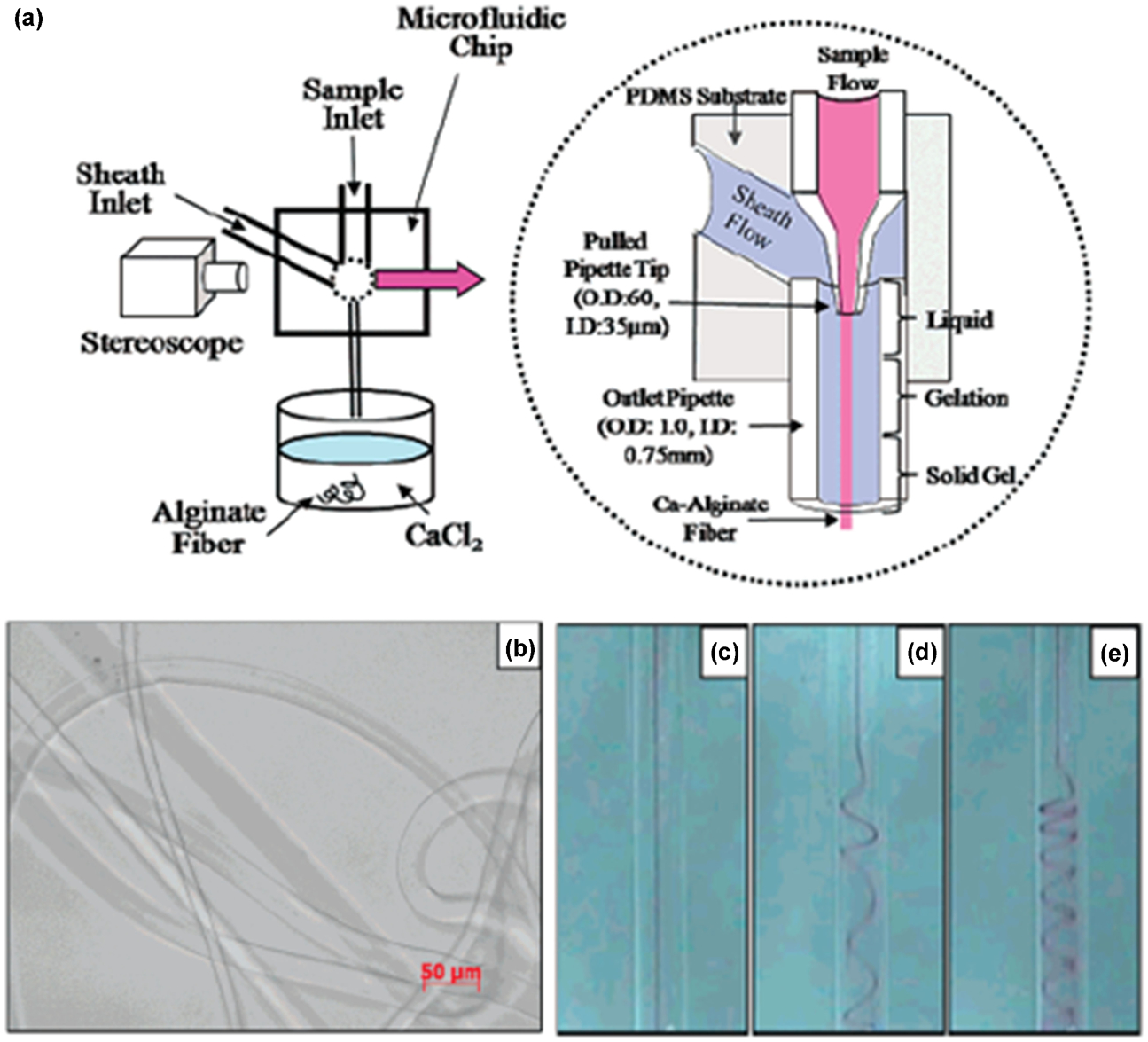
a Schematic of microfibre generation via microfluidics and principle of gelation (dotted circle). b Calcium alginate fibres produced using microfluidic system. c–e Spiral curled alginate fibres produced by varying sample flow rate flow rate from 1 to 3 to 5 μL min–1, respectively 90
Hydrogels
Hydrogels are cross-linked polymer networks that can absorb large volumes of water. They elicited attention for use in humans as early as 1960s. 91 Some early applications include ocular applications like contact lenses 92,93 and hydrogel implants like breast implants. 94 Initially, people focused on applying hydrogels as stand-alone biomaterials due to their biocompatibility and physiochemical similarity with the native extracellular matrix (ECM) in terms of water content, water retention and mechanical properties. The recent successful employment of hydrogels for cell encapsulation 95,96 and controlled release of bioactive materials 97 led to intensive studies in the field of tissue engineering and regenerative medicine, including wound healing, tissue repair and biosensors. To meet the demands of different biomedical applications, complex hydrogels, such as interpenetrating networks (IPNs), hybrid hydrogels and ‘smart’ stimuli-responsive hydrogels, have been developed. 98 Hydrogels with three-dimensional structures and fine features have also been investigated using advanced manufacturing approaches such as rapid prototyping techniques. 99
Hydrogel materials
Many different materials have been applied to fabricate hydrogels. Synthetic polymeric materials have been widely investigated for biomedical applications, including poly(vinyl alcohol) (PVA), poly(2-hydroxyethyl methacrylate) (pHEMA), poly(ethylene glycol) (PEG) and silicone (or polysiloxanes). These polymers provide wide flexibility in structural and mechanical properties, optical properties and other important parameters.
Poly(vinyl alcohol) (PVA)
Poly(vinyl alcohol) (PVA) is a water-soluble polymer of great interest for pharmaceutical and biomedical applications owing to its biocompatibility (Fig. 41). 100 This polymer is produced from hydrolysis of poly(vinyl acetate) (PVAc). Poly(vinyl alcohol) hydrogels are formed by cross-linking PVA chains in various ways. Chemical cross-linking of PVA hydrogels has been applied to form acetal bridges between the pendant hydroxyl groups of the PVA chains using aldehydes like glutaraldehyde, acetaldehyde and formaldehyde. Nevertheless, tedious procedures of extracting toxic reaction residues are required for biomedical applications. In order to avoid this, γ-irradiation was employed to cross-link PVA chemically. However, this technique showed bubble formation, rendering it unusable for many applications. On the other hand, PVA chains feature a unique capability to form crystallites by hydroxyl bonds and van der Waals forces. These crystallites can serve as physical cross-linkers between the PVA chains. Due to the three-dimensional structures of the crystallites, the physically cross-linked PVA hydrogels demonstrate enhanced mechanical strength compared with the chemically cross-linked ones. An efficient way to crystallize aqueous PVA solutions was demonstrated by Peppas and other researchers using freezing and thawing techniques. 101,102 Increased PVA crystallinity was obtained by increasing freezing time. Yet, long-term stability of the structure and morphology of the PVA hydrogels was a potential issue because slow recrystallization or dissolution of the PVA crystallites could happen at different conditions. In order to avoid any harsh environment to prepare PVA hydrogels, Schmedlen et al. 103 investigated photoactive PVA derivatives functionalized with aminobutyraldehyde diethyl acetal. The photoactive PVA not only showed rapid photopolymerization under ultraviolet (UV) exposure, but also exhibited compatibility with cell seeding.
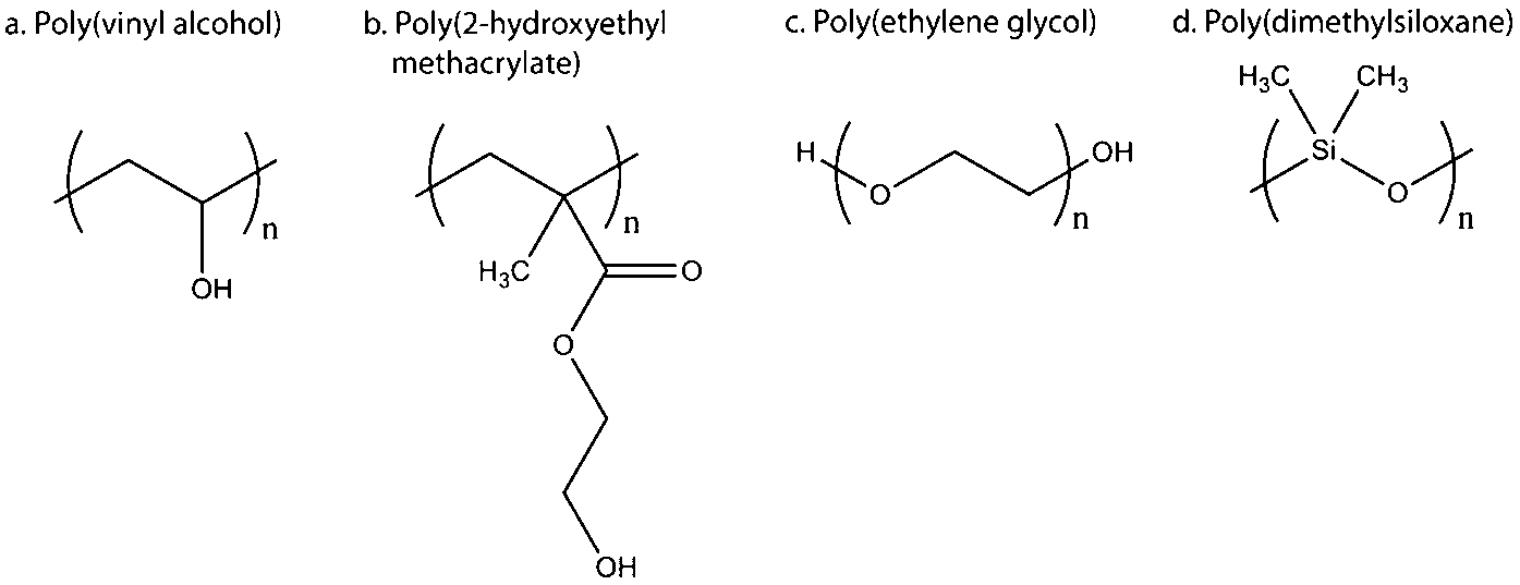
Chemical structures of synthetic polymers used for biomedical applications
Poly(2-hydroxyethyl methacrylate) (pHEMA)
Poly(2-hydroxyethyl methacrylate) is a frequently employed synthetic polymer. 104,105 The hydrogel material pHEMA is prepared by radical polymerization of 2-hydroxyethyl methacrylate (HEMA), a technique that was introduced by Wichterle et al. 92 in 1960 (Fig. 41b ). As the first hydrogel material successfully applied for biomedical applications, pHEMA is the main component of disposable soft contact lenses today. PHEMA hydrogels show great transparency, excellent biocompatibility, moderate water absorption and relatively limited oxygen permeation. Therefore, a great number of copolymers have been incorporated into the HEMA hydrogels to enhance the water content and oxygen diffusion.
For this purpose, different hydrophilic monomers have been employed to form pHEMA-based composite hydrogels, including methacrylate (MA), N-vinylpyrrolidinone (NVP) and glyceryl methacrylate (GMA). Hydrogels based on pHEMA have also been studied intensively for other biological uses, such as controlled drug release devices, 106 tissue implants 107 and nerve guidance channels. 108
Poly(ethylene glycol) (PEG)
Poly(ethylene glycol) (PEG) is a polyether polymerized from ethylene oxide by condensation (Fig. 41c ). Historically, this polyether with a molecular weight above 20 000 g mol–1 was named poly(ethylene oxide) (PEO). Actually, the molecular weight of PEG plays a critical role in the renal clearance of this polymer through glomerular filtration. 109 PEG below 20 000 g mol–1 was required for efficient renal clearance, while PEG below 5000 g mol–1 was preferred for rapid clearance in the human body. In this regard, PEG below 5000 g mol–1 has been widely applied to prepare hydrogels.
The discovery of PEG with non-immunogenicity, bioinertness and hydrophilicity was a significant finding in the field of tissue engineering. 110 Pure PEG can serve as an ideal inert matrix to diminish immune response and prevent protein absorption. Moreover, the convenient conversion of the hydroxyl end groups of the PEG into a variety of different functional groups triggered tremendous studies of PEG modification and the use of modified PEG for biomedical applications, including drug delivery devices, tissue engineering scaffolds and medical implants. 111 PEG end groups have been successfully functionalized with acetylene, acrylate, amine, azide, carboxyl, methyloxyl, thiol, vinyl sulfone, etc. PEG can have a linear chain with the same or different functional groups at the two ends, and it also can have branched structures with multi-functional groups at each end. The functional end groups of PEG can further be conjugated with bioactive molecules like peptides, proteins and oligonucleotides.
The availability of different PEG functional end groups allows the use of various cross-linking methods to prepare PEG hydrogels, including chain-growth reaction such as free radical polymerization of PEG acrylates, and step-growth reaction such as condensation, Michael-type addition and click chemistry. 97 Free radical polymerization using light, i.e. photopolymerization, is the most widely employed approach to fabricate PEG hydrogels. This method shows several advantages. First, the reaction is usually rapid and only takes a few minutes to complete. Second, the reaction requires mild environments compatible with physiological temperature and pH. Third, the reaction provides high flexibility of tuning biological and mechanical cues of the PEG hydrogels, which is important for regenerative medicine applications. For instance, PEG-conjugated biomaterials can be easily copolymerized into the PEG hydrogel. Therefore, PEG hydrogels prepared by photopolymerization are highly preferred for encapsulation of cells and biomaterials that require strictly mild conditions. Recently, our group and others have focused on in situ polymerization of liquid polymer solutions incorporated with cells and/or bioactive factors. 112,113 Efficient and biocompatible photo-initiator systems have been developed for transdermal photopolymerization of PEG hydrogels using light in the UV and visible wavelength regions. This method shows great potential in minimally invasive applications by implanting polymer delivery devices without the need for surgical intervention. Hydrogels prepared by click chemistry, on the other hand, have demonstrated dramatically improved mechanical properties owing to highly specific and quantitative features of this reaction under physiological conditions. 114 Anseth and co-workers recently developed a variety of click hydrogels capable of patterning spatially and temporally, which allows incorporation of distinctive biochemical functionalities and tuning of subtle cell–biomaterials interactions. 115–117
PEG itself is non-degradable naturally. To control the degradation of PEG hydrogels, a series of degradable moieties have been incorporated into PEG networks. 118–120 Hydrolytically degradable segments, such as poly(glycolic acid) (PGA), poly(lactic acid) (PLA), polycaprolactone (PCL) and their derivatives and copolymers, are commonly used. Biodegradable PEG macromers typically feature a triblock polymer structure, e.g. PLA–PEG–PLA terminated with acrylate being able to photopolymerized into the PEG hydrogel. The degradation rate of the PLA–PEG–PLA hydrogels was found to depend on the PLA segment length and polymer content in the hydrogels. Hubbell and co-workers enhanced the biodegradability of PEG hydrogel by utilizing Michael-type addition to form thiol–acrylate cross-linkers in the hydrogel. 121,122 Recently, they developed novel enzymatically degradable PEG hydrogels by incorporating a group of peptides cleavable by plasmin and/or matrix metalloproteinases (MMPs). 123 These PEG hydrogels soon elicited researchers’ particular interests. The PEG matrix allows cell-induced enzymatic remodelling and provides a template to investigate various cell–biomaterials interactions such as cell proliferation, spreading, differentiation and invasion.
Silicone
Silicones, or more precisely, polysiloxanes, are polymers consisting of an inorganic silicon–oxygen backbone with organic side groups, such as methyl, ethyl or phenyl, attached to the silicon atoms. Silicone with methyl side groups, called polydimethylsiloxane (PDMS), was used most widely in biomedical applications, including breast implants, contact lenses, blood pumps, cardiac pacemaker leads, bandages and dressings. 124 The widespread use of PDMS based materials can be attributed to these materials’ excellent stability, softness, biodurability and blood compatibility. Nevertheless, some long-term implantation issues of silicone devices led to clinical complications, which caused the US Food and Drug Administration to issue a moratorium on silicone gel breast implants for cosmetic purposes in 1992. 94 Recently, silicone hydrogel contact lenses have gained great popularity and commercial success for extended wear owing to their high oxygen permeability in comparison with pHEMA-based hydrogels. 92,93 This unique property of silicone can be explained by the chain mobility of the silicon–oxygen backbone and bulkiness of the side groups. Silicone itself is hydrophobic and thus limits the wettability of the hydrogel surface. Various methods have been applied to improve the hydrophilicity/wettability of silicone, including physical techniques such as corona, plasma and laser treatments, and chemical techniques such as surface grafting with hydrophilic polymers like PEG.
Hydrogel properties
Hydrogels are characterized as highly swollen cross-linked polymeric networks and can be classified based on the polymer source and cross-linking type. 125,126 Hydrogels made from both naturally and synthetically derived polymers have been investigated. Natural hydrogels potentially produce favourable biodegradation products and allow for directing/controlling cell behaviour such as adhesion, growth, migration and differentiation. Natural scaffolds, such as collagen, HA, alginates and chitosan, have been widely tested and applied clinically. Nevertheless, naturally derived materials suffer a greater risk of contamination and immune reaction than synthetically derived materials. On the other hand, synthetic hydrogels can be processed from a plethora of options and provide higher flexibility to tune chemical, physical and biological properties. Combinatorial uses of both naturally and synthetically derived materials in hydrogels have also attracted great attention, with the goal of combining the advantages from each component. Hydrogels can be cross-linked via chemical and/or physical bonds. Chemical hydrogels are formed by covalently cross-linked networks, which are more stable and provide higher mechanical strength compared with physical hydrogels. In contrast, physical hydrogels allow cross-linker formation requiring no addition of toxic reactants such as chemical hydrogels, and so avoid potential side effects.
Several important factors play a role in determining the physical–chemical properties of hydrogels: comonomer composition, volume fraction, average molecular weight between cross-links and correlation length (Fig. 42), and polymerization conditions (pH, reaction time, temperature). 97,127 Altering the composition of a hydrogel by increasing the relative amount of a physically stronger component will lead to increased strength of the hydrogel, e.g. by replacing acrylates with methacrylates, or it could alter hydrophilicty by replacing 2-hydroxyethyl methacrylate with methacrylic acid, for example. Volume fraction is defined as the ratio of the volume occupied by the polymer to that of the hydrogel. When the hydrogel is swollen in equilibrium state, volume fraction describes the degree of the swelling and sometimes is estimated from the weight fraction because it is more convenient to determine the weights of the polymer and hydrogel. Cross-link density of the hydrogel determines the average molecular weight between cross-links, which is correlated with the distance between cross-links, called correlation length or network pore size. All of these factors influence hydrogels in various ways, including permeability, molecular diffusivity, elastic deformation and modulus. For example, Table 8 reports mechanical properties of an HEMA–acrylic acid comonomer hydrogel, varying up to orders of magnitude as a result of pH and cross-linker concentration. 128 In other studies, increasing the fraction of N-vinyl-2-pyrrolidone (NVP) relative to HEMA or methyl methacrylate (MMA) resulted in one to two orders of magnitude reduction in Young’s modulus, which is due to the highly hydrophilic nature of NVP relative to HEMA or MMA, causing an increase in swelling. 127,129,130 In a hydrogel containing ionic monomers, varying the ratio of cationic and anionic monomers affected swelling, leading to maximum swelling (60 or 100%) when all of the monomer was either positively or negatively charged, but less than 20% swelling when the cationic and anionic monomers were present in equal amounts. 127,131 As the volume degree of swelling of polyacrylamide gels cross-linked with N,N-methylene-bisacrylamide changed from 4 to 8, the elastic modulus decreased by nearly two orders of magnitude (from 10 5 to 10 3 Pa). 132 In the work by Greenberg and Kusy, 133 increasing allyl acrylate cross-link agent concentration in acrylic acid polymers was shown to increase dynamic modulus significantly and glass transition temperature linearly. 127 These examples illustrate the sensitivity, and therefore tailorability, of hydrogel properties to composition and synthesis conditions.
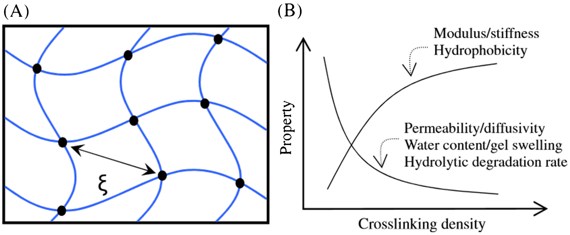
a Simplified structure of cross-linked hydrogel. Cross-linking point is indicated by black dots. The distance between cross-links is called correlation length, ξ, or network pore size. b The cross-linking density of hydrogels strongly influences gel properties, including modulus/stiffness, hydrophobicity, permeability/diffusivity, water content/gel swelling and hydrolytic degradation rate 97
Effect of (a) pH and (b) wt-% cross-linker of hydrogel mechanical properties 128
Fibre-reinforced hydrogels
Just as glass fibre-reinforced plastics (GFRP), also known as fibreglass composites, have become commonplace today for a multitude of structural applications, fibre-reinforced hydrogels have similar potential in biomechanics and other fields. The hydrogel community has started venturing into this research area by examining the properties of both natural fibre-reinforced hydrogels (e.g. cartilage) and synthetic fibre-reinforced hydrogels (e.g. polyurethane fibres in an epoxy–amine hydrogel). One can think of the impact of using reinforcing fibres as broadening the mechanical properties window of any given hydrogel. For example, imagine that a hydrogel alone is only suitable for utility in a compression application from 0 to –20 MPa of stress. When reinforced with suitable fibres, the same hydrogel may be able to handle tension and compression at higher stresses and strains. The challenge for fibre-reinforced hydrogels arises when even more requirements are placed for certain applications. For example, a transparency requirement may lead to limitations on the reinforcing fibre diameter and the maximum volume fraction tolerable. As we enter the century of biology, the emergence of new hydrogel composite materials may enable heretofore unseen applications in both the commercial and defense sectors. The sub-sections below describe recent work in tailoring the mechanical properties, optical properties and biological properties of fibre-reinforced hydrogels.
Mechanical properties
Natural hydrogels such as cartilage are strong and tough, whereas many synthetic hydrogels are weak. Cartilage contains micrometre scale fibres that toughen and strengthen the gel matrix, improving the mechanical properties of the overall composite. The fibres also play the role of arresting cracks that propagate through the gels, which otherwise have no barrier to propagation under tension. Understanding the roles of the hydrogel matrix and the reinforcement fibres in determining the overall mechanical properties can enable tailoring of these composites for specific applications.
As is the case for any material, the mechanical behaviour and properties of fibre-reinforced hydrogels are highly dependent on composition and processing. To achieve sufficient mechanical performance of a hydrogel in a specified application, requirements for mechanical properties, including elasticity, compressibility, viscoelastic behaviour, tensile strength and failure strain, must be specified, characterized and controlled. 134 Both the hydrogel matrix and the fibre properties are important in improving mechanical properties of hydrogel composites. The tensile strength of a fibre-reinforced hydrogel is largely dictated by the matrix properties, whereas the modulus is more dependent on the amount and properties of the reinforcing fibres. A strong fibre–hydrogel interface, low stress concentration and fibre orientation are required to increase tensile strength, whereas fibre concentration, fibre wetting in the matrix phase and high fibre aspect ratio determine tensile modulus. 7,135
In hydrogels, mechanical properties are affected by polymer and cross-linker characteristics, gelling conditions (e.g. temperature and pH), swelling and degradation. 127 For example, high guluronic acid containing alginate polymers yielded stronger, more ductile hydrogels than high mannuronic acid containing alginates. 136 Increases in polymer volume fraction have also resulted in an increase in both the compression modulus and the equilibrium shear modulus for alginate, 137 PEG 138 and PVA hydrogels, 139 for example. The mechanical properties and swelling degrees of hydrogels can also be tightly tailored by employing different kinds of cross-linking molecules and controlling the cross-linking densities. 140 Gel swelling usually results in a decrease in the mechanical strength of hydrogels, 127,138 but these can be independently controlled in covalently cross-linked hydrogels by varying both the cross-linker type and its density. 140 Hydrogel degradation and dissolution usually lead to a weakening of the gels 136,137 unless tissue in-growth acts to strengthen them 138 or these properties are decoupled. 141 Overall, by controlling the specific polymer and processing methods, a wide range of tensile properties is available from hydrogels. 136
Hydrogels on their own have poor mechanical properties, in general, but incorporation of fibres can enable improvement and tailoring of mechanical properties. Fibre composition, geometry, content, orientation and interaction with the hydrogel matrix all play a role in determining the final composite properties. For example, Kai et al. 142 studied the effects of incorporating electrospun poly(ϵ-caprolactone)/gelatine nanofibres into hydrogels and demonstrated increases in Young’s modulus from 3·29±1·02 to 20·30±1·79 kPa and decreases in strain at break from 66·0±1·1% to 52·0±3·0% (Fig. 43). A 1–2 wt-% reinforcement of bacterial cellulose in methacrylate hydrogels led to a 10- to 20-fold increase in storage modulus and also significant increases in loss modulus of the gels. 143 In a study by Agrawal et al., 144 a pultrusion system was used to build three-dimensional patterned fibrous polyurethane structures, which were then impregnated with epoxy–amine hydrogel to form a fibre-reinforced hydrogel composite (Figs. 44a –45d ). They observed that 5 wt-% fibre reinforcement improved the tensile modulus of hydrogel from 0·7 to 2·5 MPa, breaking strength from 0·2 to 1·3 MPa and breaking strain from 30% to around 150%. The influence of the fibres on crack propagation, namely crack blunting, can be seen in Fig. 44e . Generally, as the concentration of fibres in a hydrogel is increased, the stiffness increases and swelling decreases, so these co-dependent properties must be balanced for specific applications. 145,146 These examples demonstrate the flexibility in tailoring of hydrogel mechanical properties provided by incorporation of fibres.
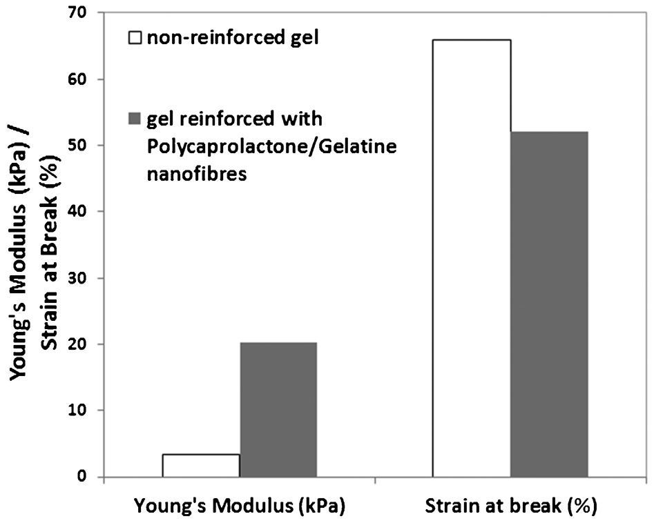
Adapted from Ref. 142
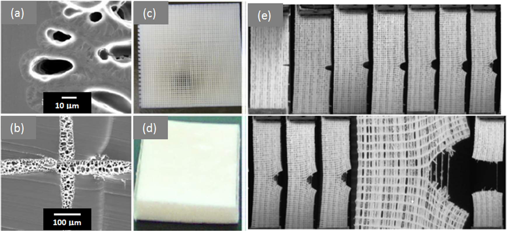
a, b Cross-sectional images of fibre-reinforced hydrogels, c fibre construct prior to impregnating with hydrogel and d final fibre-reinforced hydrogel. e Series of time lapse images showing propagation of a crack, which blunts owing to the presence of fibres
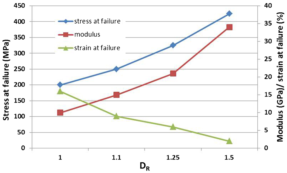
Relationship between the tensile strength (σf), modulus of elasticity (E), elongation at break (ef) and draw ratio (DR) for cellulose films 158
Alignment of fibres within a matrix leads to enhanced mechanical strength in the direction of alignment. Anisotropic hydrogels can thus be proposed. In addition, fibre alignment can have benefits for wound healing applications. 87 As a consequence, many techniques are employed to align fibres within hydrogel matrices. Controlled ordering of polymer fibres can be accomplished to a degree via application of strong magnetic and electric fields. Preferred orientation has been induced in suspensions of cellulose nano- and microfibrils using both magnetic 147–149 and electric fields. 150,151 While cellulose shows orientation perpendicular to an applied magnetic field, 147–149 orientation is parallel in an electric field. 151,152
Drawing of polymer fibres and films can change mechanical properties of the material by introducing preferred orientation. Drawing can be performed during consolidation from liquid to solid, or in solid state below the glass transition temperature (cold drawing) or at an elevated temperature. 153–157 As a result of drawing, the molecular chains in a polymer gradually align with the direction of applied strain, which in turn introduces mechanical anisotropy. Drawing cellulose films in the wet condition and subsequent drying has been employed by Gindl and Keckes. 158 As shown in Fig. 45, their study resulted in significant increases in tensile strength and modulus of elasticity and decreases in elongation at break of self-reinforced cellulose films in the direction of draw.
Optical properties: transparency, refractive index match
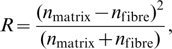
To produce a transparent fibre-reinforced hydrogel, it is imperative to either match the refractive index (within ∼0·001) of a relatively large (>400 nm) diameter fibre to that of the hydrogel matrix or to keep the reinforcement fibre’s dimension much less than 400 nm (the shortest wavelength of visible light) such that light does not reflect and refract according to Fresnel’s and Snell’s laws at each fibre–hydrogel interface. Even in the case of nanofibre reinforcements without a perfect index of refraction match between the nanofibre and the hydrogel matrix, there still exists some scattered light which is given by equation (2),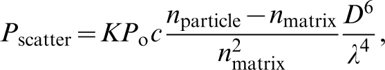
For reinforcements larger than the wavelength of visible light, one is mostly concerned with multi-bounce Fresnel reflections at the fibre–matrix interface and the standard transmittance through the material (as a function of reflectance and absorption). Through a given thickness of one phase material, the transmittance is given by equation (3),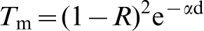
In polymer–fibre composites, where the fibres are larger than the wavelength of visible light, there are tremendous challenges in obtaining high transparency over a wide wavelength regime at different temperatures. The nature of the challenge lies in the fact that the refractive index of materials is a function of wavelength and temperature. Therefore, matching indices in dissimilar materials at one wavelength and temperature may be feasible, but doing so over broad wavelength and temperature becomes challenging from the perspective of materials design. As an example, one can consider Weaver et al.’s 162 work in which they tried to index match glass fibres in PMMA to achieve strong, stiff transparent composites. Figure 46 shows the transmission as a function of wavelength and temperature for a PMMA matrix with 10·4 vol.-% BK10 glass fibre of 13 μm diameter. In the visible regime from 400 to 750 nm, the transmittance of neat PMMA is ∼92%. However, when PMMA–glass fibre composites are fabricated, strong variations in transmittance as a function of wavelength and temperature are observed. In a detailed study of glass fibre-reinforced epoxy, Iba et al. 160 demonstrated that through careful synthesis, a broad range of optical and mechanical properties is feasible, with the general trend that the light transmittance improves at the expense of the specific modulus and tensile strength, as shown in Fig. 47. Iba et al. also concluded that higher light transmittances could be achieved only through much closer matching of the refractive indices of the fibre and matrix.
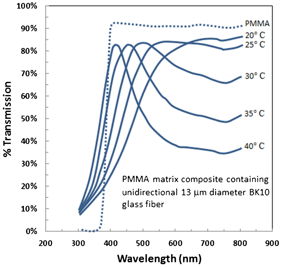
Temperature dependent optical transmission for as-cast pressure-cured (65°C/6·9 MPa N/18 h) PMMA matrix composite [236 mil (5·99 μm) thick] containing 10·4 vol.-% of 13 μm diameter glass fibre dip coated with 3-(trimethoxysilyl)propyl methacrylate 162
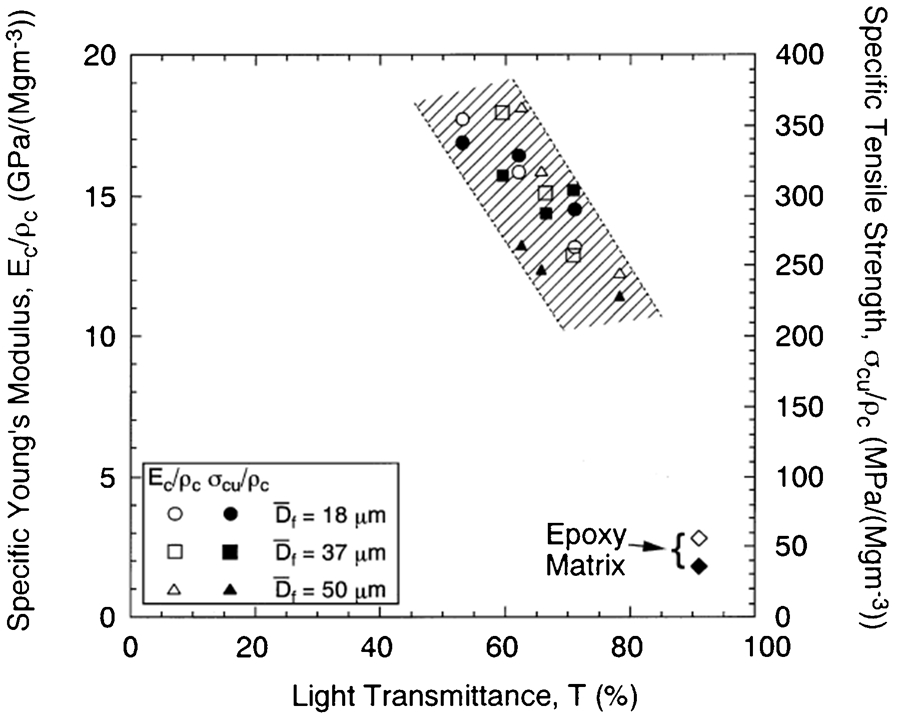
Specific Young’s modulus and specific tensile strength of the composites versus the light transmittance at a wavelength of 800 nm 160
While research into relatively large fibre-reinforced composite polymers for high optical transmittance and good mechanical properties has encountered the aforementioned refractive index matching problem, Nogi et al. 21 demonstrated that nano-sized bionanocellulose fibre reinforcements in polymer matrices tolerate a much larger refractive index mismatch, leading to concomitant high transmittance and mechanical properties (Fig. 48). Thus, it is apparent that strategies employing nanofibre reinforcements may be advantageous from a materials composite fabrication and resultant properties perspective.
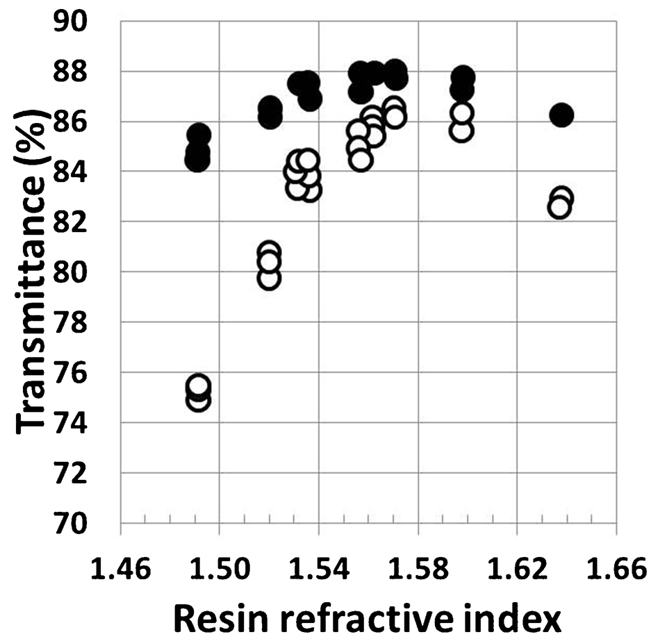
Total transmittance (solid circles) and regular transmittance (open circles) of BC nanocomposites at 20°C and 590 nm versus the refractive index of their resins at 20°C and 589·3 nm
When one is considering reinforcing a hydrogel, it is helpful to know the refractive index of the hydrogel. Short of measuring it experimentally using an Abbe refractometer, one can calculate the expected refractive index by employing a volumetric rule of mixtures. Table 9 shows the approximate volume fractions of water and polymer in a hydrogel and the range of expected refractive indices for the hydrogels. For a hydrogel made from a polymer that has a refractive index of approximately 1·5, the expected hydrogel refractive indices all range from 1·34 to 1·373, depending on the water content. At such low refractive indices, glass, ceramic and most polymer materials will have refractive indices so much higher than the hydrogel matrix that one is advised to consider a nano-sized reinforcement owing to the less stringent ‘requirement’ for index matching to achieve reasonably high transparency.
Range of refractive indices expected for a hydrogel
An interesting fibre-reinforced hydrogel composite was recently described by Agrawal and Calvert, 163 in which they developed a robotic method to mimic the process of spider web formation. While their resultant fibre-reinforced hydrogels were not completely transparent, gaps between the reinforcements were. For example, Fig. 49 shows a woodpile structure and a radially varying (spider web-like) structure deposited using their robotic dispensing system. In particular, Fig. 49c shows the hydrogel–fibre composite. If the fibres were transparent themselves and were shrunk in size and spaced appropriately, a significant transparency might be realized because the hydrogel matrix is transparent. Agrawal et al. 164 have also recently reported strong synthetic hydrogels reinforced with elastic fibres fabricated using a 3d rapid prototyping technique.
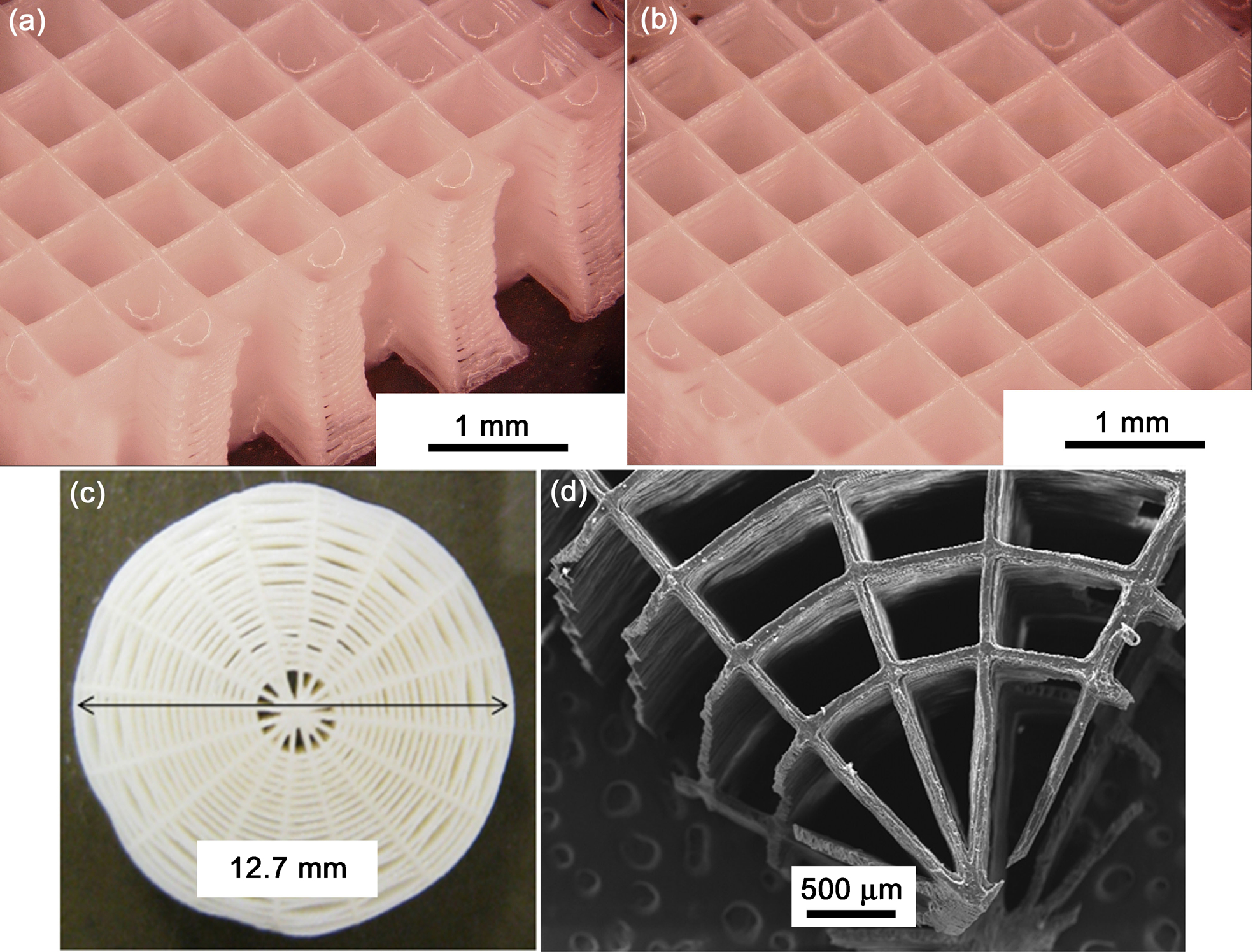
a, b Woodpile structure consisting of 40 layers; each layer is about 25 μm thick. 163 c Fibre–gel composite structure consisting of 12 mm diameter fibres, 250 layers; each layer is about 25 μm thick. d Magnified view of the reinforcement structure shown in c (courtesy of P. Calvert)
Water-soluble low and high molecular weight hydrogel films reinforced with NFC have been synthesized and tested by Fernandes et al. 165 The films showed interesting mechanical and optical properties. For example, images of the neat high molecular weight chitosan hydrogel and 5, 10 and 20 wt-% NFC reinforced chitosan are shown in Fig. 50. It can be seen that the 5 wt% reinforced chitosan film is still very optically clear, whereas the higher loadings of NFC lead to more diffuse transmission of light. The transmittance data shown in Fig. 51 provide quantitative, wavelength dependent transmittance information for the different loadings of NFC in chitosan. The 5 wt% NFC loaded chitosan spectra nearly perfectly overlap with those of the neat chitosan film ranging from ∼88% to 90% across the visible spectrum. The NFC reinforced chitosan films exhibited a maximum of ∼150% improvement in Young’s modulus compared with the unreinforced chitosan films.
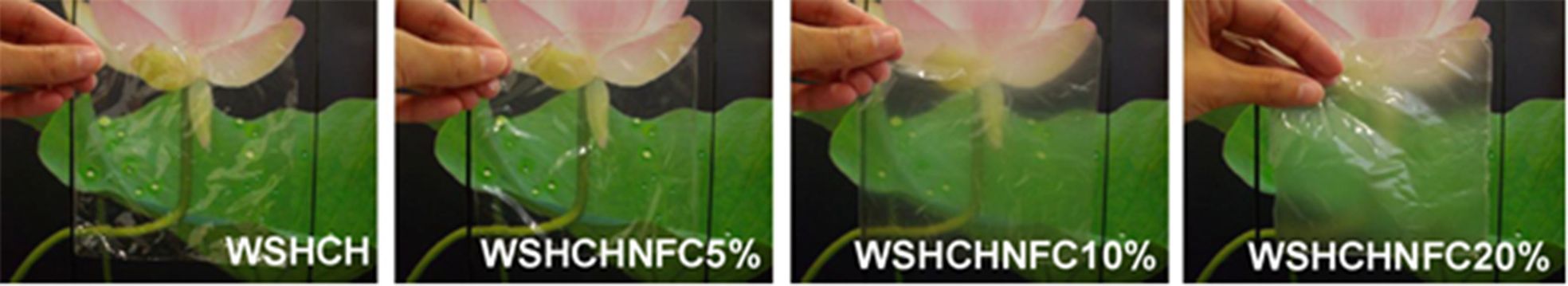
Images of the water-soluble, high molecular weight chitosan (WSHCH) nanocomposite films containing different percentages of nanofibrillated cellulose (NFC) 165
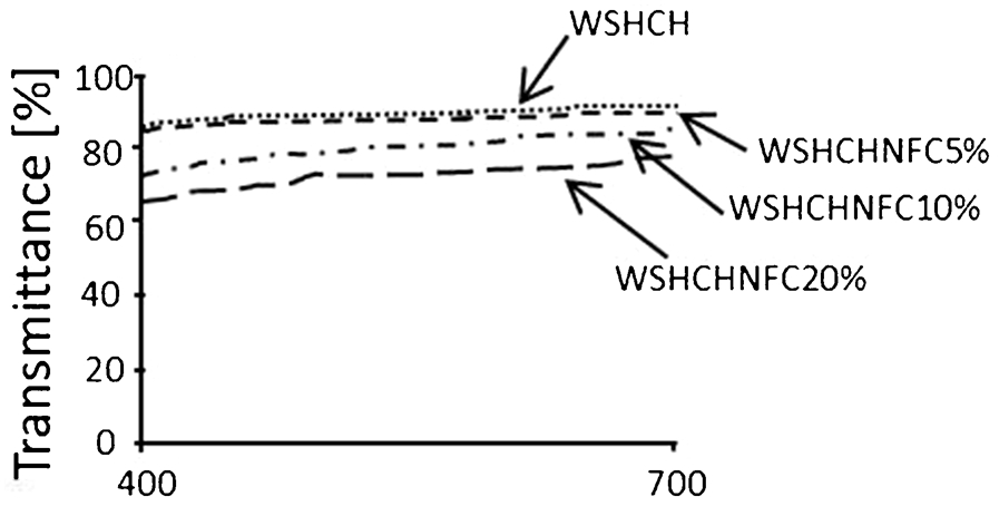
Transmittance of the WSHCH nanocomposite films containing different percentages of nanofibrillated cellulose (NFC) 165
Biological functionality
Polymer scaffolds have many different functions in the field of tissue engineering. They are applied as space filling agents, as delivery vehicles for bioactive molecules and as three-dimensional structures that organize cells and present stimuli to direct the formation of a desired tissue. Recently, research focus has been increasing on hydrogels for use in regenerative medicine applications requiring more challenging biological functionalities. 111 In native tissues, cells are surrounded by ECM, which is mainly composed of structural fibrous proteins (e.g. collagen, elastin and fibrin) embedded in polysaccharide rich glycans (e.g. GAGs and PGs) (Fig. 52a ). The protein fibrils provide mechanical support as a physical framework for cells and tissues, while the highly negatively charged glycans serve as the ground substrate between protein fibrils to maintain a hydrated state and provide a reservoir for signalling molecules and growth factors.
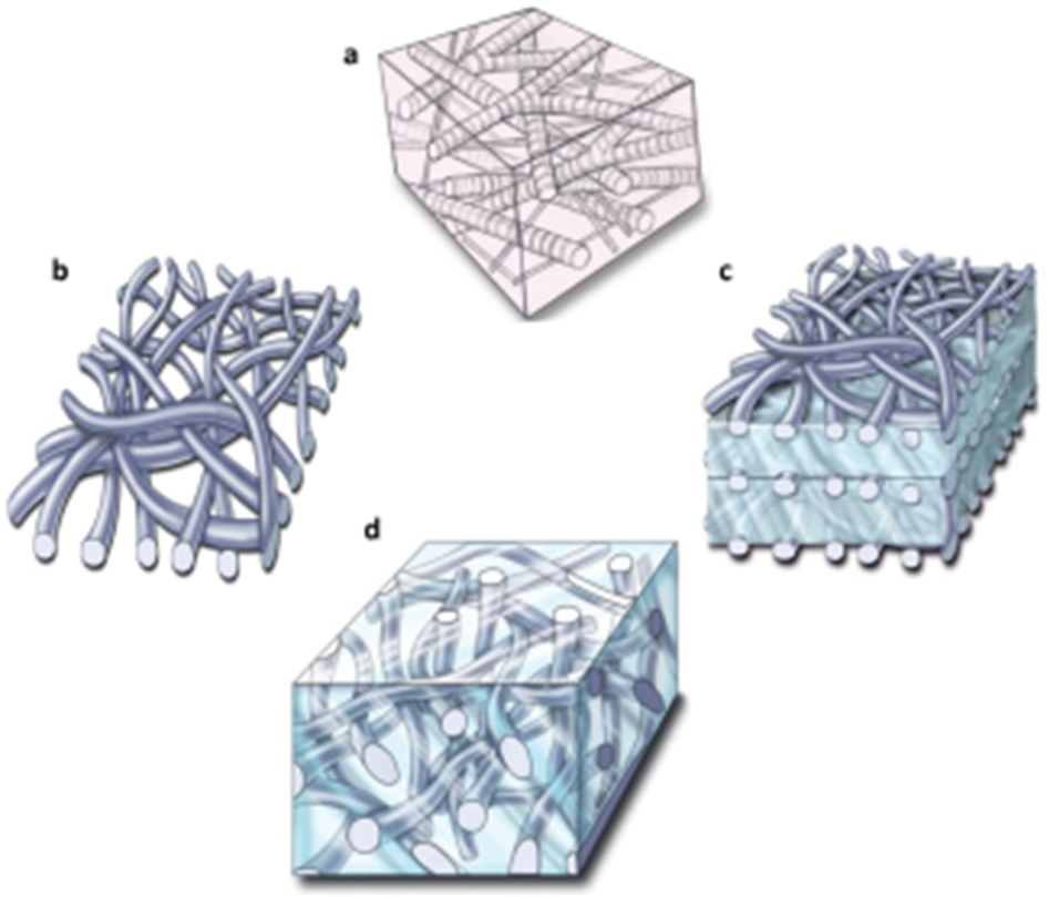
a native ECM composed of protein fibrils as physical framework and highly negatively charged glycans as ground substrate, b dense fibre mats produced from a conventional electrospinning technique, c multi-layered fibre–hydrogel composites made from dense fibre mats stacked with hydrogels and d fibre-reinforced hydrogel made from hydrogel embedded, low density fibres fabricated using a novel electrospinning technique 166
Beyond simple hydrogels, fibres (both micro and nano) can be incorporated into hydrogels to further mimic the ECM. Fibre-reinforced hydrogels have the advantage of mimicking the chemical, biological and physical composition of native ECM for different biomedical applications. Recently, a novel electrospinning technique was developed to fabricate loose polymer fibre matrix with macroscale pores, which allowed engineering of a three-dimensional fibre–hydrogel composite for clinically relevant tissue defects. 166 Bulk three-dimensional fibre-reinforced hydrogels were studied using PCL fibre mats embedded in PEG hydrogels incorporated with cell adhesive peptides of arginine–glycine–aspartic acid (RGD) (Fig. 52d ). As shown in Fig. 53, the mesenchymal stem cells (MSCs) encapsulated in the composite showed a variety of cell morphologies including extensions, indicating cell interactions with the fibrous scaffolds. In contrast, when using hydrogels alone, the cells exhibited spherical morphology. The fibre density in the composite was found to play an important role in cell matrix production with the greatest amount produced at a fibre density of 10% dry weight. Multi-layered composites were also tested to replicate tissues with layered structures such as skin and cornea (Fig. 52c ). Mesenchymal stem cells encapsulated in this composite demonstrated enhanced chondrogenic differentiation with higher GAG and collagen production. Furthermore, MSCs in this composite showed greater response to mechanical stimulation, which can be attributed to the more efficient force transduction from the composite scaffold to the cells, compared to the pure PEG hydrogel.
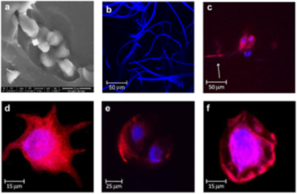
a SEM image of fibres embedded in the hydrogel, b confocal microscopy image of the hydrogel composite with fluorescent stained fibres, c–e in the fibre-reinforced hydrogel, mesenchymal stem cells (MSCs) long extensions and dividing nuclei, f in the pure hydrogel, cells showing a round morphology 166
Applications
Hydrogels have been used in many different types of applications such as medical/biosensors that respond to specific chemical or biological molecules, microarrays that can be used to immobilize cells locally on a substrate, contact lenses, medical electrodes, tissue engineering of various organs (e.g. collagen hydrogels for the liver, skin and blood vessels and other hydrogels for bone and cartilage), controlled drug delivery and diagnostic imaging applications. Many applications of hydrogels would benefit from optical transparency. Contact lenses are one application requiring optical clarity. In addition, hydrogel wound dressings, sensors that rely on fluorescent markers embedded within hydrogels, or ocular prostheses, which begin their reconstructive journey as hydrogels all would benefit from optical transparency and clarity. The following sections will describe applications in which transparent and/or improved mechanical strength hydrogels could find significant utility. One important note related to natural fibre-reinforced hydrogels is that natural fibres are a renewable resource with an unlimited supply in nature, 25,44,167 which can render the cost significantly lower for a product utilizing them relative to a product that relies on synthetic fibres. The reader is also encouraged to examine other insightful review articles on applied hydrogels for diverse biological/medical applications. 125,168,169
Ocular applications for transparent and improved strength hydrogels
Apart from standard contact lens material needs for daily wearers, there is significant opportunity for the development of new and improved hydrogels for corneal patch and corneal prosthesis applications. For example, despite the eye’s seemingly insignificant size, accounting for only 0·1% of the body’s frontal silhouette, the incidence of ocular injury in combat has been shown to be 20–50 times greater than expected by its surface area. 170 As a function of time in US history, the percentage of eye wounds compared with total reported injuries in various wars and conflicts has been increasing dramatically (Fig. 54). Novel materials for treatment on the battlefield to improve outcomes are needed, along with new materials to serve as corneal prostheses for subsequent eye surgery in a clinical setting once the wounded service person can be evacuated from the theatre of war.
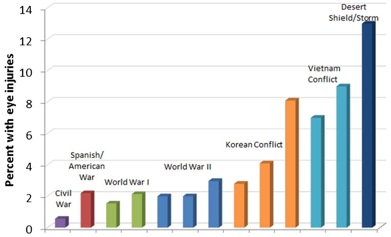
Adapted from Ari 170
A novel combination of chondroitin–sulphate polyethylene glycol (CS-PEG) adhesive and vitrified collagen gels (CV) shows promise for the repair of open globe ocular injuries commonly sustained on the modern battlefield or in civilian trauma. 171 Injury models were based on photographs of actual combat injuries and created in porcine cadaver eyes before repair with CS-PEG alone, CS-PEG+CV, or sutures (control), as shown in Fig. 55a . Burst pressure testing was used to assess success of repair, with materials withstanding pressures past 50 mmHg considered successful. These data are summarized in Figs. 55b and c. For linear defects, CS-PEG+CV membrane was comparable to sutures in its ability to seal the eye, but may prove advantageous during the healing process due to the biocompatibility of the materials and the nature of the less invasive repair procedure. Additionally and perhaps more significantly, suturing of circular defects or lacerations with tissue loss is not possible due to the severe astigmatism that would result, but reconstruction with CS-PEG+CV was demonstrated to be successful at repair of large circular injuries with diameters up to 8 mm. The biosynthesized CV membrane holds great potential in its physical and biological properties and drug delivery capability. This new material also may enable repair of previously irreparable ocular injuries.
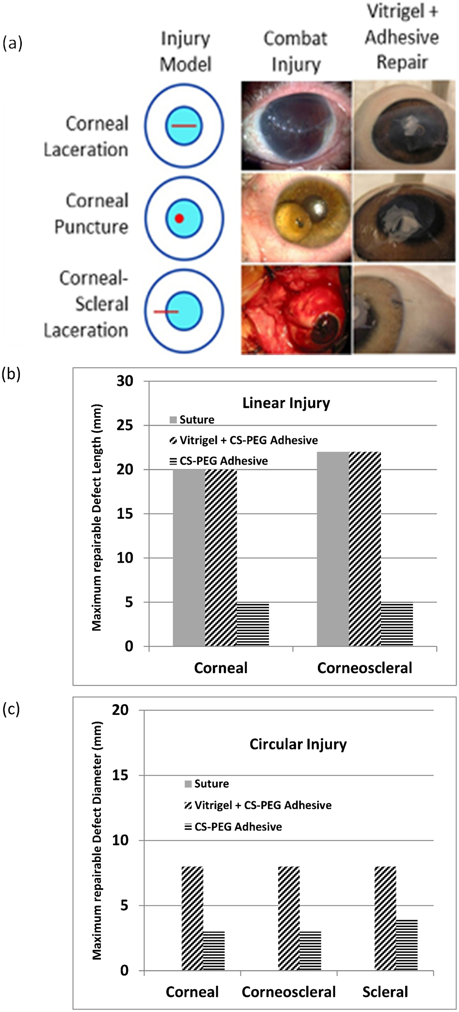
Adapted from Mulreany et al. 171
Load-bearing tissue applications for improved strength hydrogels
There are several load-bearing applications in which hydrogels can be utilized. One potentially useful application for hydrogels is as an interface material between bone and implants. Netti et al. 172 showed that pHEMA hydrogels are promising replacements for bone cement in cases where it is desirable to fix a bone–joint prosthesis interface. The concept is that the hydrogel is placed in the correct position between the bone and the prosthesis in a dehydrated state. The hydrogel subsequently absorbs water from its surroundings and swells until its hydrostatic pressure in the material is equal to the osmotic pressure of water in the system. While Netti et al.’s in vitro pull-out mechanical testing was very promising, the in vivo testing showed some significant variations in results and indicated lower relative pull-out forces. The less promising in vivo test results were attributed to differences in morphology of the animal anatomy from sample to sample. While the mechanical tests in vivo were inconclusive, the histological examination showed that the pHEMA hydrogel had potential as a biomaterial adjacent to bone because there was no evidence of adverse reaction in the bone to the material. For example, new bone was observed to form a shell around the hydrogel 28 days after implant (Fig. 56).
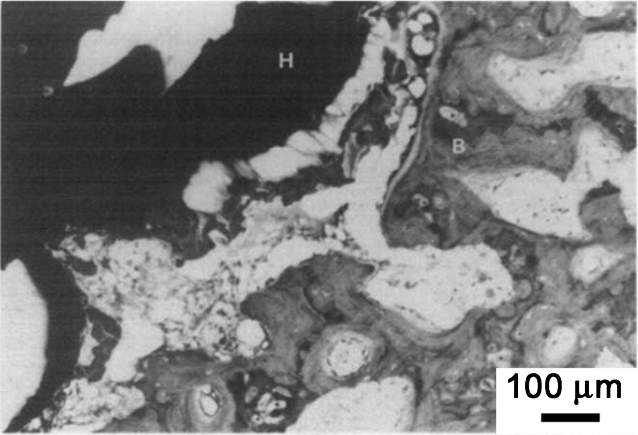
New bone (B) forming a shell surrounding the hydrogel (H) 28 days after implantation in the metaphysis 172
Another application for load-bearing hydrogels is intervertebral disc replacement. Nucore is an injectable protein-based nucleus replacement which thermal cures in situ. 173 Since the cured hydrogel is larger than the injection site, a mechanical barrier is formed and the hydrogel, which also has adhesive properties, resists extrusion. This injectable silk elastin polymer and cross-linker combination is undergoing investigational device exemption feasibility study. Intervertebral disc replacement hydrogels that cure via photopolymerization are also under development. 174
Collagen has also been used in a variety of load-bearing applications. It can be isolated from a variety of sources and is relatively non-immunogenic. 49 Wood hemicellulose and cellulose nanowhiskers were also used to successfully prepare a fibre-reinforced hydrogel that has superior toughness, extensibility, and recovery properties compared to conventionally cross-linked hydrogels. 175 The improved properties along with satisfactory water holding capacity, mechanical properties, and viscoelasticity make the reinforced hydrogel an interesting candidate material for articular cartilage replacement.
Wound management applications for transparent and improved strength hydrogels
Burn wounds and chronic venous ulcer wounds are difficult wounds to treat with dressings because many dressings do not adequately serve the wound. For example, some dressing materials may not facilitate good transfer of oxygen to the wound for healing while others may not be able to donate or absorb water/exudates from the wound or may permit too much moisture loss from the wound site. Sticking to the wound during dressing removal also presents significant pain and re-injury to the patient. One excellent material for such wound treatments is bacterial cellulose. The material is shown in Fig. 57 and has almost all of the above positive attributes (e.g. it has excellent oxygen permeability and can effectively absorb exudate and hydrate dry areas of a wound, which is unique in comparison with other dressings that have only a single function 176 ) except for the fact that although Czaja et al. 12 claim that the material is transparent and allows for continuous clinical observation of the healing process, the material still looks rather opaque. A truly transparent dressing with all of the attributes of bacterial cellulose and significant conformability yet high ultimate tensile strength and tear strength would revolutionize the burn wound standard of care.
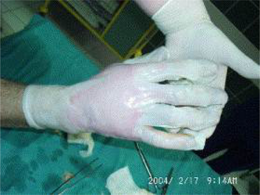
Microbial cellulose dressing applied on a wounded hand. The unique physical properties of microbial cellulose allow an excellent moulding, displaying a high degree of adherence even to the moving parts 12
Alginate has been used in applications in the food, textile, printing, paper and pharmaceuticals industries. 25 Owing to their non-toxicity and ability to hold a large amount of water, alginate gels, foams and fibrous non-woven dressings have been applied to wound healing. The exchange of calcium ions in alginate fibres with sodium ions in the body causes a release of calcium ions, which act as a haemostatic agent. 25 As calcium alginate fibres convert to sodium alginate fibres, large amounts of exudates are absorbed. 25 In their dry form, these materials absorb wound fluid, whereas in their hydrated form they donate water to the wound. This helps to maintain a moist environment, which promotes quicker migration of the epithelial cells from the edge of the wound to the bulk. 25 It should also be noted that chitin and chitosan are natural polymers that are biodegradable, biocompatible and non-toxic and have an ability to accelerate wound healing. 32,177
Sensing/device applications for transparent and/or improved strength hydrogels
A novel hydrogel based glucose sensor has recently been developed and reported by Holtz and Asher. 178,179 The researchers relied on Bragg diffraction for the sensing technique. In creating a photonic crystal by fabricating an array of small polystyrene spheres, functionalizing the spheres with glucose oxidase, and then polymerizing the polystyrene spheres into a hydrogel, the researchers created a visible light sensor that changes colour as the local environment’s glucose concentration varies. For patients with diabetes mellitus, the sensor could essentially be used as part of a contact lens for real-time non-invasive sugar monitoring, as shown in Figs. 58 and 59. A small region of the lens would contain the modified photonic crystal hydrogel patch and the colour of the patch would change with the level of glucose in the tears of the subject. When the sensor is designed with appropriate sensitivity and wavelength range, the colour changes would be quite stark and easily noticeable for the wearer. It should be noted that hydrogel reinforcements, particularly at the edge, for contact lenses or pseudo-contact lenses like the ones discussed here, are expected to improve handling performance for wearers.
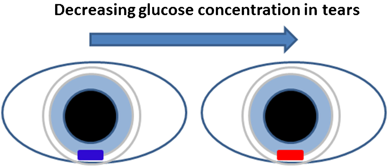
Pictorial representation of use of glucose-sensing material in a contact lens-like application, adapted from Ref. 179
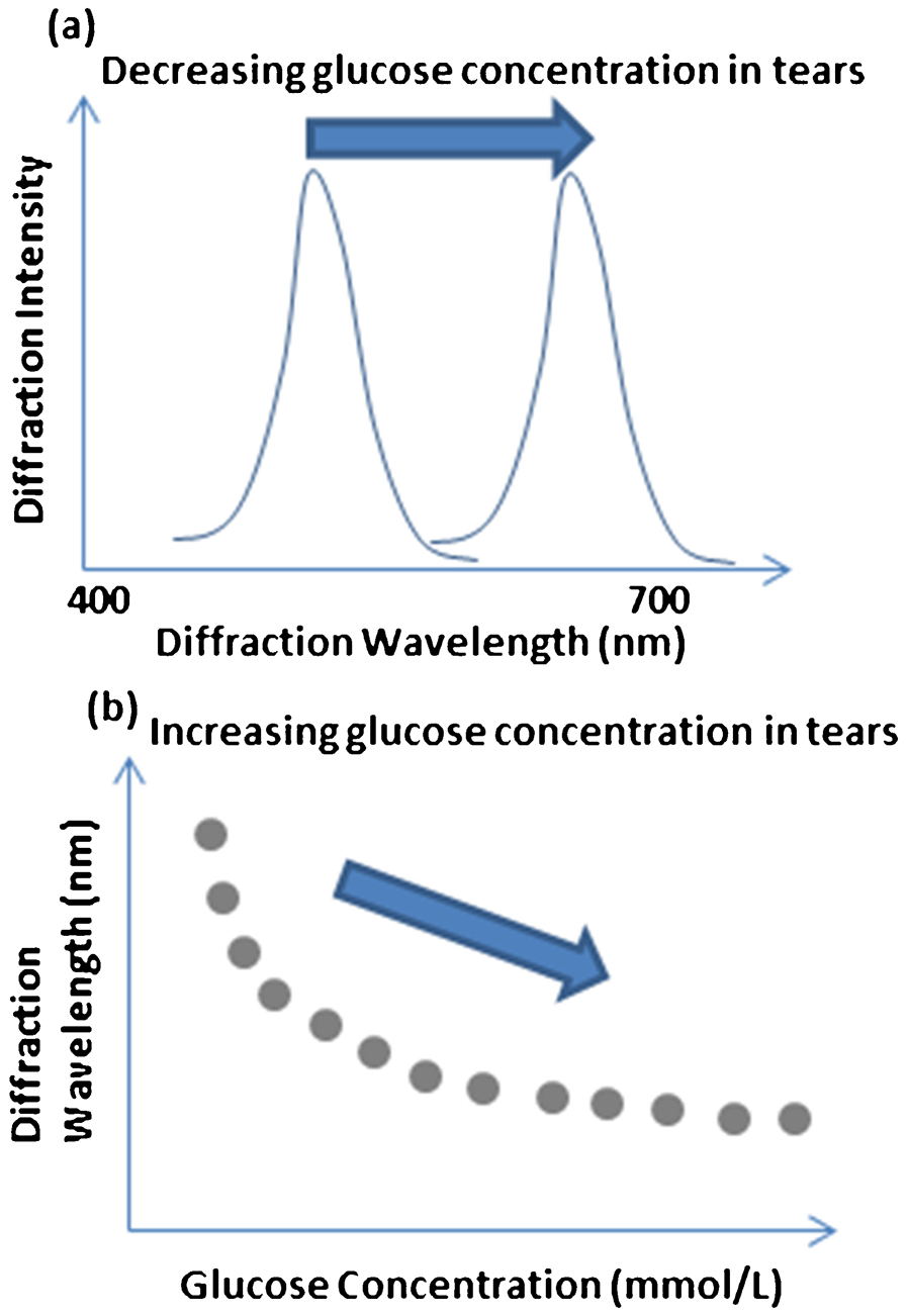
Effects of glucose concentration on the optical properties of the hydrogel based photonic crystal glucose sensor. a spectral shift trend as a function of glucose concentration; b peak diffraction wavelength trend as a function of glucose concentration, adapted from Ref. 179
Perspectives for the future
The future for advanced reinforced transparent hydrogel materials is bright in many different regards. Exciting advances are being made by individual researchers in the area of nanoscale reinforcement fibres, which could add significant mechanical property improvements to hydrogels without serious detriment to the optical transmittance and clarity. Innovative methods to produce the nano-reinforcement fibres such as electrospinning, microfluidic template biosynthesis and solvent extrusion of both natural and synthetic materials are creating new possibilities for reinforced hydrogels. Researchers are also continually improving their understanding of hydrogels and reinforced hydrogels through improved characterization methods. The knowledge gained empirically as well as through advanced physics based modelling techniques (e.g. full-wave solution optical modelling for nano-materials embedded in a medium are possible now) will allow researchers to cycle through the engineering loop much more rapidly than ever possible before. Transparent reinforced hydrogels could really be ‘game changers’ in the field of wound care by allowing observation without dressing removal and by providing improved mechanical durability, and they could be augmented to provide sensory functionality and drug delivery. Ocular applications (bandage and prosthetic) are another obvious domain where stronger, highly transparent reinforced hydrogels could be extremely important both in the commercial and the military sectors. A future is now possible in which nanofibre reinforcements for hydrogels are readily synthesized with well characterized, predictable and uniform properties such that they could be either self-assembled or be directly assembled in a specific orientation to serve as important reinforcement elements in application specific hydrogel matrices to yield scalable, novel materials that provide improved medical outcomes and new in vivo and environmental sensing opportunities.