
Abstract
Yttrium silicates (Y–Si–O oxides), including Y2Si2O7, Y2SiO5, and Y4·67(SiO4)3O apatite, have attracted wide attentions from material scientists and engineers, because of their extensive polymorphisms and important roles as grain boundary phases in improving the high-temperature mechanical/thermal properties of Si3N4 and SiC ceramics. Recent interest in these materials has been renewed by their potential applications as high-temperature structural ceramics, oxidation protective coatings, and environmental barrier coatings (EBCs). The salient properties of Y–Si–O oxides are strongly related to their unique chemical bonds and microstructure features. An in-depth understanding on the synthesis – multi-scale structure-property relationships of the Y–Si–O oxides will shine a light on their performance and potential applications. In this review, recent progress of the synthesis, multi-scale structures, and properties of the Y–Si–O oxides are summarised. First, various methods for the synthesis of Y–Si–O ceramics in the forms of powders, bulks, and thin films/coatings are reviewed. Then, the crystal structures, chemical bonds, and atomic microstructures of the polymorphs in the Y–Si–O system are summarised. The third section focuses on the properties of Y–Si–O oxides, involving the mechanical, thermal, dielectric, and tribological properties, their environmental stability, and their structure–property relationships. The outlook for potential applications of Y–Si–O oxides is also highlighted.
Introduction
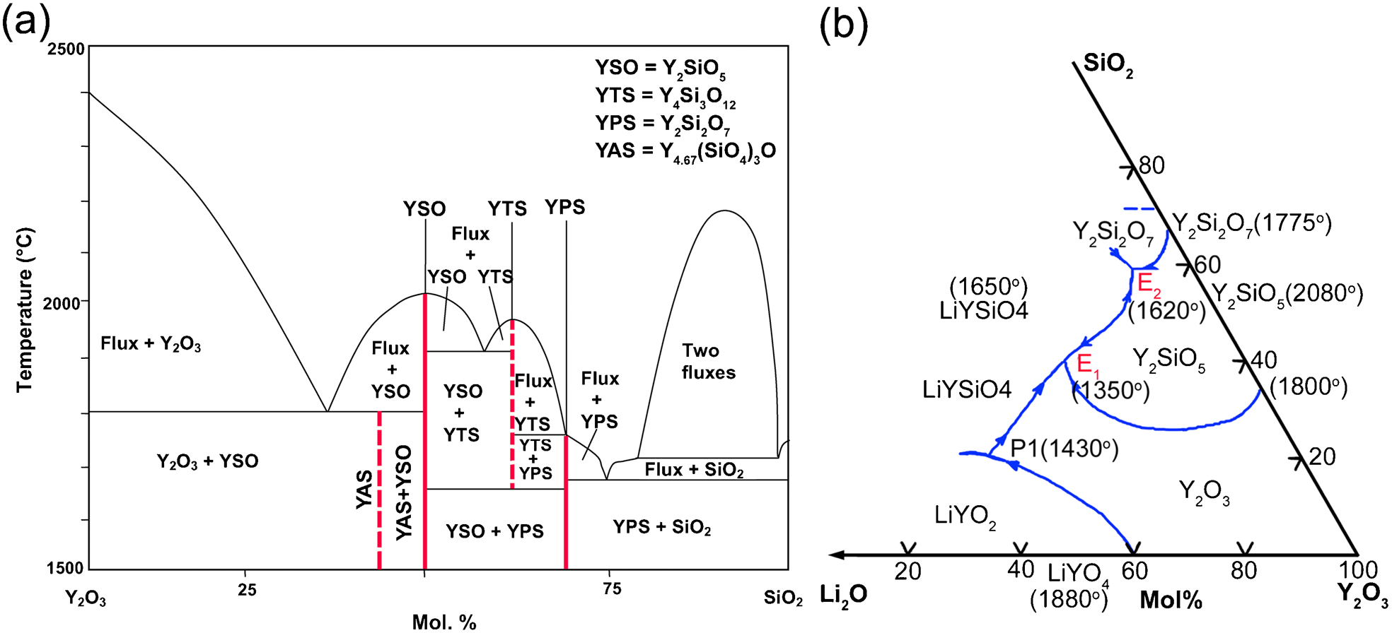
Yttrium silicates, or the Y2O3–SiO2 binary system (Fig. 1a ), including Y2Si2O7, Y2SiO5, and 2Y2O3.3SiO2, were first discovered from an yttrialite ore yard located in Texas, USA in 1889. Thereafter, similar yttrialite mines were discovered in different places around the world, such as Japan and Russia. 1–3 Although the chemical compositions for these yttrialites were the same for the ores taken from different mines, the reported crystal structures showed a wide diversity. Moreover, the crystal structure also varied depending on the heating history. 1–4 The crystal structure diversity of yttrialites was found to be the result of polymorphisms. The extensive polymorphisms of yttrialite attracted the strong interest of material scientists, such that the polymorphisms and the crystal chemistry of Y–Si–O oxides were widely studied. 4–8 Bondar and Toropov 9 pointed out that there were three ternary crystalline phases, namely, Y2SiO5, Y2Si2O7, and 2Y2O3.3SiO2, with melting points of 1980, 1950, and 1750°C, respectively, in the binary Y2O3–SiO2 system. However, according to the later investigations, 2Y2O3.3SiO2 was stable only in the presence of other divalent or monovalent cations. 10 Later, an apatite structure, Y4·67(SiO4)3O (2·34Y2O3.3SiO2), was determined as the dashed line shown in Fig. 1a . In the solid-state synthesis of Y2SiO5, Y4·67(SiO4)3O apatite always appears as second phase.
In 1968, Ito and Johnson
11
reviewed the crystal structures, X-ray diffraction (XRD) data, polymorphism transformations, and the differences between natural and synthesised yttrium disilicates (Y2Si2O7), wherein six polymorphs were reported, namely, α-, β-, γ-, δ-, y-, and z-Y2Si2O7. These phases could be transformed from one to another at varying temperatures: 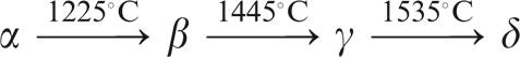
The high melting points of Y–Si–O oxides enable their potential applications as high-temperature structural materials or multifunctional coatings. Recent interest in yttrium silicates was renewed by the roles they play at the grain boundaries of Si3N4 and SiC. It was found that the high-temperature mechanical properties and the thermal conductivities of Si3N4 and SiC were dramatically improved when yttrium silicates were formed as grain boundary phases. 14–19
In this review, recent progress on novel preparation methods, and the multi-scale structures and properties of Y–Si–O oxides (Y2Si2O7, Y2SiO5, and Y4·67(SiO4)3O apatite) are summarised. The first part focuses on synthesis of powders, sintering of bulk ceramics and deposition of coatings/films. Owing to the complex polymorphism of yttrium silicates 11–13,20–22 and the strict stoichiometric ratio required for the starting materials, 23,24 the synthesis of single-phase yttrium silicates is a major obstacle to the research and application of these oxides. At present, the main preparation methods employed for powders are sol-gel (including the precipitation technique), 25–34 hydrothermal synthesis, 35–38 solid–solid reaction, 39–42 solid–liquid reaction, 43–47 high-P/high-T synthesis, 21 and molten salt flux growth (or the Czochralski technique); 20,39,48–51 and for coatings and thin films are chemical vapour deposition (CVD), atomic layer deposition (ALD), radio frequency (rf)-sputtering, magnetron sputtering, pulsed laser deposition (PLD), plasma spraying, electrophoretic deposition (EPD), spin coating, and dip coating, 40,52–57 etc. The features and merits of these methods are summarised in this section.
The second section introduces the crystal structure, chemical bonding, and microstructural characteristics of Y–Si–O oxides. Recently reported crystal structure data of ζ-Y2Si2O7, η-Y2Si2O7, and Y4·67(SiO4)3O apatite are collected. Confusion about the structures of yttrium silicates is also clarified.
In the third section, properties of Y–Si–O ceramics are reviewed. Some yttrium silicates, such as γ-Y2Si2O7 and Y2SiO5, have low shear deformation resistance and are tolerant to mechanical damage. 58,59 γ-Y2Si2O7 exhibits low thermal expansion coefficient (TEC, 3·90×10−6 K−1) and low thermal conductivity (<3·0 W m−1 K−1 above 600 K), while Y2SiO5 presents a slightly higher TEC (8·36×10−6 K−1), but extremely low thermal conductivity (1·34 W m−1 K−1). 60,61 Moreover, Y–Si–O ceramics have been proven to have excellent resistance to hot corrosion, even in strongly basic Na2CO3 molten salt, 62,63 which indicates that Y–Si–O ceramics are promising candidates for oxidation-resistance/thermal barrier/environmental barrier coatings (EBCs). Defect formation in Y–Si–O oxides 64,65 will also be presented. Finally, the outlook for potential applications of the Y–Si–O oxides is highlighted in the last section.
Preparation of Y–Si–O oxides
Synthesis of powders and sintering of bulk ceramics
In the binary Y2O3–SiO2 phase diagram, Y2SiO5, Y2Si2O7, and Y4·67(SiO4)3O, are presented as straight lines (Fig. 1a ), 10,23,24 thus the synthesis of single-phase Y–Si–O compounds needs very strict control of the stoichiometric Y/Si ratio. The extensive polymorphisms also hinder the preparation of single-phase Y–Si–O oxides. Low-temperature polymorphs may appear during cooling. For example, after heating sol-gel prepared Y2Si2O7 powders to 1200°C, a mixture containing α-Y2Si2O7 and β-Y2Si2O7 was obtained. 26 The sintering of nearly theoretically dense Y–Si–O bulk is also a challenge because of their poor sinterability and the temperature-dependent phase transformations.
Up to now, the common synthesis methods for Y–Si–O powders are: (i) sol-gel, 25–34 (ii) hydrothermal, 35–38 (iii) solid-state reaction, 28,39–42 (iv) solid–liquid reaction, 43–46 (v) molten salt fluxing growth, 20,39,48–51 (vi) high-P/high-T synthesis, 21 etc. For bulk Y–Si–O oxides, the Czochralski technique is used for single-crystals, while pressureless sintering and hot pressing are employed for polycrystalline samples. 45–51 Table 1 summarises the typical methods, processing conditions, and predominant products for the fabrication of Y–Si–O compounds. The overall procedures for these preparation methods are generally described as follows.
Summary of typical preparation methods for Y–Si–O oxides
TEOS: tetraethyl orthosilicate.
Sol-gel synthesis of Y2Si2O7 and Y2SiO5 25–34
Usually, a solution of tetraethyl orthosilicate (TEOS) is added to an aqueous solution of Y(NO3)3 to form a transparent sol. Then, a homogeneous Y2O3/SiO2 gel is obtained by drying the sol at temperatures below 600°C. By calcining the gel at 600–1050°C, phase-pure α-Y2Si2O7 or X1-Y2SiO5 can be obtained. X2-Y2SiO5 can be obtained by further heating the sol-gel prepared X1-Y2SiO5 powders to higher temperatures. Via the sol-gel method, Fe-doped Y4·67(SiO4)3O apatite (or Fe0·2Y4(SiO4)3O0·2) has also been successfully synthesised from yttrium nitrate, iron nitrate, and TEOS solution. 34 The apatite is very stable at ∼1700°C in nitrogen atmosphere, but it becomes metastable in air even at lower temperatures (950–1150°C), and decomposes into Y2Si2O7 and Y2SiO5. 34
The advantages of the sol-gel method include easy composition control, low synthesis temperature, and suitability for coating on different substrates. For Y2Si2O7, however, preparing single-phase β-, γ-, or δ-Y2Si2O7 is still a challenge. The expensive precursors are also a challenge for volume production.
Hydrothermal method
Single-phase y-Y2Si2O7 can only be synthesised in the presence of a small amount of foreign metal cations, such as Na+, K+, Mg2+, Ca2+, Al3+, etc., via the hydrothermal method. 35–38 In this process, layered clay, saponite or smectits, is suspended in Y(NO3)3 solution, and then heated to 300°C or above in a hydrothermal tank for several days. The solid product collected by filtering was y-Y2Si2O7. 35,38
This route requires extended processing time, on the order of 100 days at 300°C. Autoclaving time can be reduced to approximately 11 days at the high processing temperatures. The long reaction time and the difficulty in product separation from the unreacted solid raw components are the main drawbacks of this method.
Solid-state reaction method
For solid-state reaction synthesis of Y2Si2O7 and Y2SiO5, Y2O3 and SiO2 powders are mixed by ball milling and then heated at high temperatures. 28,39–42 High reaction temperatures (usually in the range of 1300–2200°C) and long reaction times (several to hundreds of hours) 42 are needed. Even so, the synthesis of single-phase γ- or δ-Y2Si2O7 is not easy. One reason is the slow inter-diffusion between the Y2O3 and SiO2 particles, which leads to Y4·67(SiO4)3O, Y2O3, or SiO2 being left as impurities. 34,42 The other reason is that the low-temperature polymorphs appear during the cooling process, unless a very fast quenching rate is employed. 42 Fe-doped Y4·67(SiO4)3O apatite (or Fe0·2Y4(SiO4)3O0·2) was also synthesised by the solid-state reaction of Y2O3 and SiO2 powders. 34
Solid-liquid reaction method
Solid–liquid reaction is characterised by lower synthesis temperature and shorter reaction time, since the formation of a low-temperature liquid phase accelerates the mass transportation and improves the chemical reaction between the starting particles. 43–46 Solid–liquid reaction inherits the merits of solid-state reaction, such as low-cost raw materials, simple equipment, and feasibility for volume production.
Leskelä and Jyrkäs 43 studied the solid–liquid reaction of Y2O3–SiO2 using different fluxing reagents such as LiF, NaF, PbF2, NH4F, NaOH, NaNO3, MgO, CaO, MgSO4, and KNO3, in which lithium compounds, especially lithium fluoride, gave the highest conversion efficiency. High-purity Y2SiO5 was obtained at 1100°C with 3 wt.-% LiF. Later, Aparicio et al. 44 prepared bulk Y2SiO5 with 90% of theoretical density by colloidal processing followed by sintering at 1600°C for 3 h using Al2O3 as a sintering aid. MacLaren et al. 45 synthesised a γ-Y2Si2O7 with 86% of theoretical density by employing a 3 wt.-% LiF fluxing additive with hot pressing at 1600°C under 10 MPa.
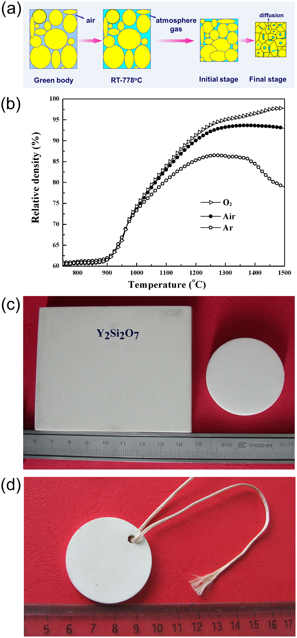
Sun et al. 46,47 prepared single-phase γ-Y2Si2O7 and X2-Y2SiO5 powders and bulk materials via the solid–liquid reaction method using LiYO2 as additive at 1400–1500°C. From the Y2O3–SiO2–LiO2 phase diagram (Fig. 1b ), the reaction temperature between Y2O3 and SiO2 can be lowered by eutectic reactions induced by LiO2. 66 Sun et al. observed the formation of Li-containing liquid phase at ∼1000°C. 46,47 Figure 2 presents the significance of the solid–liquid reaction in the synthesis of Y–Si–O oxides by comparing the differential scanning calorimetry (DSC) of the Y2O3/SiO2 and Y2O3/SiO2/LiYO2 mixtures (Fig. 2a ), and the corresponding XRD patterns after DSC test (Fig. 2b ). 46,47 Without LiYO2, exothermic peaks only resulted from crystallisation of SiO2. The addition of LiYO2 changed the reactions between the Y2O3 and SiO2. γ-Y2Si2O7 and X2-Y2SiO5 were respectively detected in the XRD patterns in the samples with different Y2O3/SiO2 ratios. Figure 2c–d shows the XRD patterns of single-phase γ-Y2Si2O7 (Fig. 2c ) and Y2SiO5 (Fig. 2d ) synthesised via the solid–liquid reactions at 1400 and 1500°C, respectively. Sun et al. pointed out the direct use of LiO2 might not be as effective as LiYO2 because LiO2 might be evaporated at high temperatures. 67 LiYO2 presents a lower vapour pressure, only partially evaporates at 1600°C 68 and had been used in the liquid phase sintering of Si3N4.
a Differential scanning calorimetry (DSC) thermographs of Y2O3/SiO2 and Y2O3/SiO2/LiYO2 powder mixtures heated to 1450°C at the rate of 2°C min−1; b the corresponding X-ray diffraction (XRD) patterns after the DSC test; XRD patterns of c γ-Y2Si2O7 and d Y2SiO5 with the addition of 3 mol.-% LiYO2 after holding at 1400°C for 4 h 46,47
Molten salt flux growth method (Czochralski technique)
Y2O3 and SiO2 powders are mixed with low melting point flux oxides such as Bi2O3, V2O5, Li2O, Na2O, Li2Mo2O7, etc., and then melted in Ir or Pt crucibles. By pulling the seed crystal from the melt slowly, single-crystals of Y2Si2O7 and Y2SiO5 40–140 mm in diameter and 50–150 mm in length can be obtained. 20,39,48–51 A similar method, i.e. the glass crystallisation method was also reported for the synthesis of yttrium silicates from the melt. In this method, Y2O3 and SiO2 powders were melted in a crucible at ∼2100°C, and amorphous glass was obtained after cooling down. The glass was then annealed at different temperatures in air to obtain the final crystals such as β-, γ-, and δ-Y2Si2O7. 14,42
High-pressure/high-temperature (high-P/high-T) synthesis
η-Y2Si2O7 was discovered as a by-product in high-P/high-T synthesis of pyroxene-type NaYSi2O6. 21 The starting materials were SiO2, Y2O3, and Na2CO3, and the synthesis was performed at 6·0 GPa and 1350°C in a Walker-type multi-anvil device for ∼216 h. This new type of polymorphous shows a different crystal structure from those reported by Ito and Johnson 11 and Feslche. 12
Some other methods for the synthesis of Y–Si–O powders can also be found in the literature, such as the solution combustion method, 69 high-energy ball milling, 70 the phonochemical method, 71 the Pechini method, 72 etc. (Table 1).
Pressureless sintering of bulk Y–Si–O ceramics
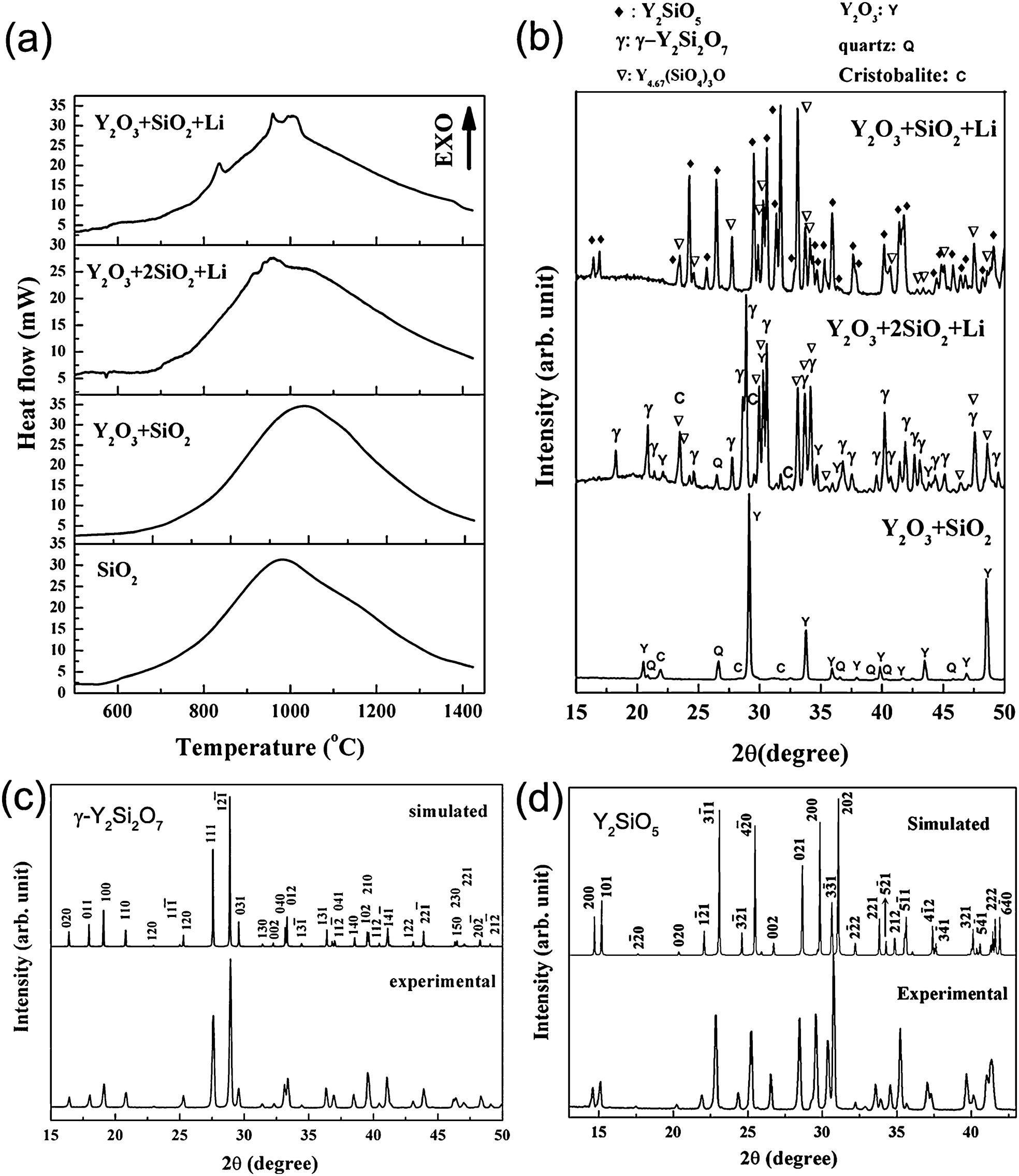
Sun et al. 46,47 successfully obtained dense, single-phase polycrystalline γ-Y2Si2O7 and X2-Y2SiO5 bulk materials by pressureless sintering of powders synthesised by the solid–liquid reaction method. Sintering atmosphere is very important for the pressureless sintering of Y–Si–O oxides. 46 Figure 3a–b presents the strong influence of atmosphere on the sintering behaviour of γ-Y2Si2O7. When constant rate sintering was conducted in oxygen at 5 K min−1 to 1500°C, densification was obviously enhanced, and the final density reached 97·5% of the theoretical. The densification was dramatically reduced in argon. This phenomenon was explained based on the solubility of the gases, as shown in the schematic (Fig. 3a ), which affects pore elimination in the final stage of sintering. Compared to oxygen, the solution and outward diffusion of nitrogen (the major component of air) and argon atoms in oxide ceramics are negligible. 73 Therefore, the elimination of the pores was much more difficult during sintering in air or argon, resulting in relatively lower densities. Figure 3c–d shows the γ-Y2Si2O7 and Y2SiO5 bulk materials obtained via pressureless sintering.
Sintering behaviour of γ-Y2Si2O7 in different atmospheres: a scheme of sintering at different stages; b shrinkage curves of γ-Y2Si2O7 in air, oxygen, and argon; c optical image of sintered γ-Y2Si2O7 bulk material; d optical image of sintered Y2SiO5 bulk material
Hot pressing of bulk Y–Si–O ceramics
MacLaren et al. 45 prepared bulk γ-Y2Si2O7 by hot pressing hydrothermally synthesised amorphous Y2Si2O7 powders with 3 wt.-% LiF additive. A dark coloured 2 mm thick plate with a density of 3·48 g cm−3 (86% of the theoretical) was obtained at 1600°C under 10 MPa. The dark colour indicates the formation of a high concentration of oxygen vacancies during the sintering in Ar.
Ogura et al. 74 obtained bulk Y2SiO5 by hot pressing Y2SiO5 powders that were synthesised from a mixture of Si- and Y-alkoxides. Hot pressing was carried out at 1400–1425°C under 27 MPa for 1–4 h in Ar. After annealing the hot-pressed samples in air at 1400–1800°C for 1–24 h, samples with 93·9–99·7% of theoretical density were obtained. The major phase was X2-Y2SiO5, accompanied by a small amount of Y2O3.
Colloidal processing of bulk Y–Si–O ceramics
Colloidal processing, including slip casting, pressure casting, and tape casting, has been widely used in shape-forming of ceramics. 75–77
Colloidal processing of Y2SiO5
Aparicio et al. 44 studied the colloidal processing of Y2SiO5. Concentrated aqueous suspensions were prepared by milling Y2O3, SiO2, or Al2O3 powder mixtures. An alkali-free strong base, c hydroxide (TMAH), was used as dispersant to achieve slip stabilisation. A carbonic acid based polyelectrolyte (Dolapix CE-64) was used to provide electrosteric stabilisation. Green bodies of the binary and ternary composites with 47–50% relative densities were obtained by slip casting. The final density reached 73% of the theoretical density after sintering at 1670°C, with the composition of Y2Si2O7 together with Y4·67(SiO4)3O as a second phase. The solid-liquid sintering was achieved with Al2O3 additive, e.g., 48Y2O3–49SiO2–3Al2O3, and the final density reached 90% of theoretical density after sintering at 1600°C for 3 h. Y2SiO5 was the major phase with small amounts of 3Y2O3·5Al2O3 and Y2Si2O7 as impurities.
Colloidal processing of γ-Y2Si2O7
Sun et al. 78,79 systematically studied the colloidal processing of γ-Y2Si2O7, which involved surface chemistry, the stabilisation mechanism of γ-Y2Si2O7 in aqueous and ethanol-based suspensions, slip casting behaviour, and microstructure control of the bulk materials via the combination of strong magnetic field alignment during slip casting and one- or two-step sintering techniques in pressureless sintering.
The surface state of oxide particles is very important in colloidal processing. Figure 4a demonstrates that the surface groups are ≡Si–OH and = Y–OH hydroxyl groups on the γ-Y2Si2O7 particles identified by Fourier transform infrared (FTIR) spectroscopy. In aqueous solution, the surface groups interact with solvent molecules and reach an ionic equilibrium (Fig. 4b ). 79 Figure 4c presents the ζ-potential curves of the aqueous γ-Y2Si2O7 suspensions as a function of pH, with or without dispersants. The aqueous γ-Y2Si2O7 suspensions without dispersant remain stable for a short term at pH 9–11·5 by electrostatic repulsion, but stability can be destroyed by the release and re-adsorption of Y3+, Y(OH)2+, and Y2(OH)2 4+ ions. The suspensions with 1 dwb% polyethylenimine (PEI) have excellent long-term stability in the pH range of 4–11·5. As shown in Fig. 4c , in the high pH range near the isoelectric point (IEP) of γ-Y2Si2O7 (pH = 10·8), the stability of the suspensions is dominated by the steric effect; at pH≈7, the stability is contributed by the electrosteric effect because of the ionisation of PEI; in the strongly acidic range, the stability mechanism is dominated by electrostatic and/or the depletion (or structural) potential.
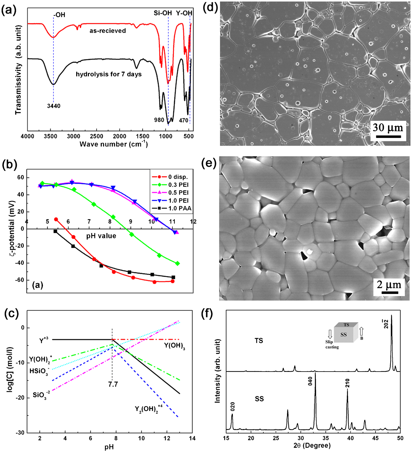
a Fourier transform infrared (FTIR) spectra of hydrated groups on γ-Y2Si2O7 particles, b ζ-potential of the γ-Y2Si2O7 suspensions, c aqueous yttrium and silicon ion equilibrium diagram as a function of pH, d microstructure of the γ-Y2Si2O7 surface perpendicular to the magnetic field direction after one-step pressureless sintering of the green bodies that were slip-casted in 12 T magnetic field; e microstructure of the γ-Y2Si2O7 surface perpendicular to the magnetic field after two-step pressureless sintering of the green bodies slip-casted in 12 T magnetic field; and f the corresponding X-ray diffraction (XRD) patterns collected from the surface perpendicular to the magnetic field direction of γ-Y2Si2O7 after two-step sintering 78,79
Sun et al.
78
also prepared well-dispersed ethanol-based γ-Y2Si2O7 suspensions using PEI as dispersant. Similar to the PEI stabilised aqueous Y2Si2O7 suspensions, a high-affinity adsorption between cationic PEI and γ-Y2Si2O7 in ethanol was observed. Slip casting of γ-Y2Si2O7 ethanol suspensions was carried out with or without 12 T strong magnetic field.
78
After slip casting, the magnetic field led to a strong 

Preparation of Y–Si–O coatings/films
Oxidation resistant coatings on SiC–C/C composites
Carbon/carbon (C/C) composites are attractive for high-temperature applications such as re-entry vehicles. 80 For most of these applications, oxidation resistant coatings are needed. 81 SiC is a reliable coating on C/C composites because of the formation of a stable SiO2 film on SiC below 1773°C, however, the vaporisation of SiO2 via SiO formation, limits its high-temperature applications. 81 Therefore, developing an outer erosion resistant layer on SiC coating is necessary. Y–Si–O oxides are favourable outer erosion resistant coatings on SiC because of their high melting points, close TECs to SiC, and low vaporisation rate. Up to now, a number of versatile Y–Si–O coating preparation methods have been reported, which are summarised in Table 2. The following is a summary of the details for the preparation of Y–Si–O coatings on C/C composites.
Summary of preparation methods for Y–Si–O coatings/thin films
PVA: polyvinyl alcohol; PLD: pulsed laser deposition; rf: radio frequency; EPD: electrophoretic deposition; BAS: barium aluminosilicate; CVD: chemical vapor deposition; ALD: atomic layer deposition.
Slurry dip coating
Preparation of Y–Si–O coatings on SiC–C/C comfposites from aqueous or organic slurry is the simplest yet efficient method, which is especially suitable for coatings on large-size components and for volume production. 56,82–88 The slurries for slip coating or dip coating usually consist of a Y2O3+SiO2 starting powder mixture, synthesised Y2SiO5, Y2Si2O7, and their composites, or sol-gel precursors. For dip coating, excellent slurry fluidity is necessary to ensure homogeneous coating. The coating can be obtained by dipping the SiC–C/C substrates into the slurry, followed by drying and sintering. Owing to the presence of porosity in the as-prepared coatings, and the cracking and spallation of the coating during service, Webster et al. 82 found that the SiC/Y2SiO5 coatings could not provide effective protection from oxidation. It has been found that an Y2SiO5+Y2Si2O7 mixture outer layer has a better performance because of its lower porosity, less cracking and spallation in service. 83 An intermediate functional glass coating was also tried for sealing the cracks during service. Aparicio and Duran 84 prepared crack free 50Y2O3:SiO2 sol-gel coatings on soda-lime glass substrates with a critical thickness of 80 nm. Homogeneous coatings with a thickness of 2 μm were also prepared by multilayer processes on SiC-coated C/C composite substrates. Unfortunately, the performance of this sol-gel coating was not examined.
Huang et al. and Smeacetto et al. 85–87 developed multilayer coatings consisting of a Y–Si–O intermediate layer and a borosilicate glass outer layer on SiC–C/C composites. The slurry for dip coating was a mixture of Si, Y2O3, distilled water, and polyvinyl alcohol (PVA) binder. The coating was obtained after drying at 80°C and sintering at 1500–1600°C for 1 h in argon. Then, the coated samples were pre-oxidised in air at 1500–1600°C for 2–10 h. Finally, a layer of borosilicate glass was applied directly on their surfaces by heating at 1500°C for 2 h in Ar. Owing to the sealing effect provided by the borosilicate glass, the SiC/yttrium silicate/glass multilayer coating exhibited good oxidation protection for C/C composites in air at 1600°C for 202 h, with a weight loss of 2·87×10−3 g cm−2. Zheng et al. 88 reported another type of multilayer protective coating obtained by separately dipping the SiC–C/C substrates into barium aluminosilicate (BAS) glass+Y2O3 and Y2O3+SiO2 suspensions. After drying and sintering at 1500°C for 2 h, a multilayer film was obtained, consisted of a Y2Si2O7 outer layer and a Celsian+Y2SiO5 inner layer. The weight loss of the double layer coated SiC–C/C composite was only 1·22% after 150 min oxidation at 1400°C.
Plasma spray coating
Plasma spraying is a very important technique that features the easy deposition of dense, homogeneous, large-size, complex shapes, and thick protective coatings. 40,89–91 Seifert et al. 40 tested plasma-sprayed yttrium silicate coated SiC–C/C in a plasma wind tunnel at 1350°C for 23 min. The results showed that the weight change of the SiC–C/C composites with the yttrium silicate protective coating was 10% less than for the samples with only the CVD-SiC coating, and was approximately 6 times (MAN Technology) and 10 times (Astrium) lower than for the C/SiC composites from industrial suppliers. The yttrium silicate coating lost its ability to protect, however, when the temperature was higher than 1700°C, where a sudden coating failure was observed by the formation of a blister at the coating/SiC interface. Huang et al. 91 reported that plasma spraying of single or multilayer coatings with the compositions of 1·5SiO2·Y2O3, 1·5SiO2·Y2O3/Y2O3, and 2SiO2·Y2O3/1·5SiO2·Y2O3/SiO2·Y2O3 gave better oxidation-resistance than the SiO2·Y2O3 coatings, since the former coatings could provide protection for SiC–C/C composites at 1500°C for 73 h.
Electrophoretic deposition
Kaya et al. 55 prepared thick Y2Si2O7 coatings on SiC/SiC composites from an α-Y2Si2O7 suspension via EPD. The solid loading was 20 vol.-% with 5 wt-% LiF sintering aid. The pH of the suspension was 9·7, where the Y2Si2O7 particle surfaces were negatively charged and deposited on the positive electrode. At constant voltage of 8 V, continuous and homogeneous α-Y2Si2O7 protective coatings with a thickness of 90 μm on SiC/SiC composites were obtained after deposition for 1·5 min followed by sintering at 1050°C for 3 h under flowing argon.
Argirusis et al. 72,92 studied the impedance spectra of Y–Si–O suspensions in EPD coatings. The impedance spectrum for the pure isopropanol was a single semicircle, which corresponded to the specific conductivity of (1·00±0·02)×10−7 S cm−1 and a dielectric constant of ϵr = 25·6±3·7. The resistances of the Y–Si–O suspensions obtained from the impedance spectra were much lower, resulting in a specific conductivity of (1·02±0·01)×10−4 S cm−1 and a dielectric constant of ϵr = 31·7±2·9. During deposition, the observed total resistance R suspension+R deposition continuously increased with time and coating thickness. For the dispersion of Y2SiO5, Y2Si2O7, and 70 wt-% Y2Si2O7+30 wt-% Y2SiO5 composite in isopropanol, a coating with an average thickness of 5 μm per deposition step at 60 V/1 min could be obtained on SiC–C/C composites. The impedance spectrum study demonstrated that the kinetics of EPD was mainly controlled by mass transport through the growing deposit. Further oxidation tests were carried out on the SiC–C/C composites with 15–30 μm Y–Si–O protective coatings, and they showed that the EPD Y–Si–O coatings provided good protection at 1500°C for more than 100 h.
Environmental barrier coatings on SiC–C/C substrate
Si-based ceramics, such as SiCf/SiC composites and monolithic Si3N4, exhibit superior high-temperature strength and durability, demonstrating their potential to revolutionise gas turbine engine technology. 93,94 A key stumbling block to realising Si-based ceramic as turbine hot section components is their lack of environmental durability in high velocity combustion environments, resulting in unacceptably high recession rates. 94,95 This can be prevented by EBCs. The candidate EBCs are mullite, yttrium stabilized c (YSZ), and BSAS (1–xBaO–xSrO–Al2O3–2SiO2, 0≤x≤1). 96–98 Some rare-earth silicates with the formulae Re2Si2O7 and Re2SiO5, where Re is a rare-earth element, have potential as promising candidates for EBCs, due to their low TEC and chemical stability. 93,99
Multilayer EBCs consisting of mullite with an Y2SiO5 top layer were prepared by Lee et al. 93 using the atmospheric pressure plasma spraying on SiC and Si3N4 and then annealed at 1300°C for 20 h. The volatilisation of the EBC top coating was tested at 1300°C and 1400°C in 90% H2O-balanced O2. A severe reaction between mullite and Y2SiO5 was observed after testing at 1400°C for 46 h, turning the entire EBC into a layer of Y2O3–Al2O3–SiO2 bubbles. This implies that Y2SiO5 may not be so competitive with Yb2SiO5, Sc2SiO5, and Lu2SiO5 when mullite is used as the base layer. A very recent report shows that γ-Y2Si2O7 has a very close TEC to those of SiC and Si3N4 and is promising as a single-layer environmental barrier coating. 60
High-κ gate dielectric thin films
Sputtering of amorphous yttrium silicate thin film
Chambers and Parsons 57 suggested that yttrium silicate possesses excellent thermodynamic, dielectric, and structural properties that make it attractive as a high-κ candidate. Moreover, Y2Si2O7 and Y2SiO5 exhibit low lattice mismatch with silicon substrate. Chambers et al. 57,100–102 sputtered yttrium films in a two-chamber vacuum system from a Y-metal target with an rf-power of 420 W on silicon substrate. Amorphous Y–Si–O film was formed by annealing the yttrium film in vacuum for 20 min, followed by annealing in air for 20 min at 900°C. The thickness of the Y–Si–O film varied between 40 and 1000 Å, depending on the thickness of the sputtered yttrium film. The electric characterisation in Al/Y–Si–O/Si capacitors suggested that there was a large charge density accumulation in the capacitors, which might have resulted from the competition between the yttrium/silicon reaction and the oxidation, leaving unsatisfied bonds. The leakage current for the n-type capacitors was less than that of silicon dioxide with equivalent capacitance, but was greater than that expected for a SiO2 film of similar physical thickness, which was consistent with the smaller barrier expected for yttrium silicate compared to SiO2.
CVD or ALD of yttrium silicates
Metal silicates can be deposited on a heated substrate by the reaction of vapours of alkoxysilanols or alkylphosphates with reactive metal amides, alkyls, or alkoxides. Such deposition techniques are referred as CVD or ALD. 103 For the CVD of yttrium silicate, a solution of tris(tert-butoxy)silanol in mesitylene and a solution of tris(tert-butyl(trimethylsilyl)amido)yttrium in mesitylene were separately pumped into a tee joint and flowed into the same heated tube. Substrates of silicon and glassy carbon placed inside the tube were coated with yttrium silicate. Films with the approximate composition of Y2Si2O7 were formed. The refractive indexes of films deposited on silicon were found to be about 1·6 by ellipsometry.
For the ALD of yttrium silicate, almost the same procedure was employed as that for CVD, except that the precursors were injected in alternate pulses spaced 5 seconds apart, instead of continuously. A film of composition similar to Y2Si2O7 was deposited with uniform thickness along the whole length of the heated zone. The thickness was about 0·3 nm per cycle.
Deposition of Y2SiO5:Ce phosphoric thin film
Phosphors are widely used in fluorescent lamps, cathode-ray tubes (CRT), and X-ray intensifier screens. 104 Y2Si2O7 and Y2SiO5 are important luminescent and laser host materials for various rare-earth activators owning to their excellent thermal and chemical stability. The PLD Y2SiO5:Ce phosphoric thin films prepared by Sun and Kwok 53 were in the range of 300–400 nm on Si(100) substrate or SiO2 coated Si substrate. Besides PLD, multilayer thin film oxide phosphors were also prepared via ion-plasma deposition by Bondar 105
Polymorphs, crystal structure, defects and microstructure of Y–Si–O oxides
Polymorphs and phase transformations
Yttrium disilicate presents up to six polymorphs: y, α, β, γ, δ, and probably z, according to Ito and Johnson.
11
The low-temperature phases (y and z) are probably stabilised by impurities.
10–13
Liddell and Thompson
10
suspected that z-Y2Si2O7 may actually be a kind of hydrated yttrium disilicate or Thanlenite with the chemical formula Y2Si2O7.1/3H2O. Recently, two new polymorphs of Y2Si2O7, which were indexed as η- and ζ-Y2Si2O7, were reported as by-products in the synthesis of other compounds.
20,21
The temperatures reported for polymorph transitions and the phase-stable ranges vary considerably from author to author.
10–13,28,39,50,106,107
Figure 5 illustrates the widely accepted polymorph transformations of yttrium disilicate by Ito and Johnson.
11
The different densities: 4·30, 4·03, 4·04, and 4·11 g cm−3 for α, β, γ, and δ, respectively,
42
suggest that the polymorph transformations are accompanied by volume change. Thereafter, different transition temperatures: 
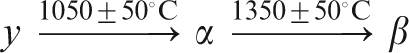
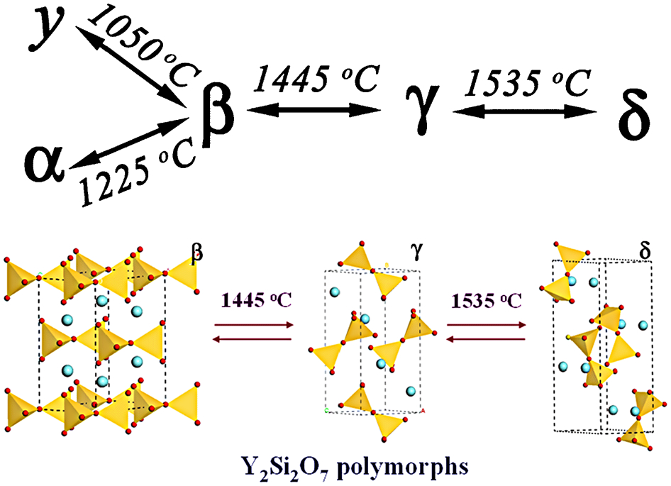
Polymorph transformations of yttrium disilicate reported by Ito and Johnson 11
Crystal structure and chemical bonding
Liddell and Thompson
10
summarised the XRD data for all the reported Y–Si–O phases in 1986. Table 3 lists the crystal structure data for the five existing polymorphs of Y2Si2O7 that were refined from the XRD data proposed by Liddell et al., together with the newly reported ζ- and η-Y2Si2O7 and those for Y2SiO5 and Y4·67(SiO4)3O.
11,115–119
Controversies on the crystal structures still exist in the literature, however. Although γ-Y2Si2O7 has been well characterised, the space group representation differs in the reports
10,36
because of the inconsistency between the chosen designation and the reported Miller indices. The designations P21/a, P21/c and P21/n are different Hermann–Mauguin representations for the same space group 
Space group, unit cell parameters and density for the polymorphs of Y–Si–O oxides
Ching et al. and Wang et al. 121–123 carried out comprehensive theoretical investigations on the Y–Si–O system via density functional theory calculations. Some experimental studies also were carried out on the crystal structures of yttrium disilicate. 10,27,28,34,36,38,50,106,124–126 The cell parameters were obtained by refining XRD data collected from Y2Si2O7 powders. 10,27,28,38,50,125 Becerro, Parmentier, and Díaz et al. 28,35,36,38,106,124,126 used 89 Y MAS-NMR and 29 Si MAS-NMR spectroscopy to clarify and differentiate chemically distinct Y and Si environments in each polymorph. According to the 89 Y MAS-NMR data for y- and δ-Y2Si2O7, only one crystallographically distinct Y site exists in the y- and δ-Y2Si2O7 unit cells instead of two, while in the well-crystallised α-Y2Si2O7, four Y sites can be clearly resolved in the 89 Y MAS-NMR spectrum. The 29 Si MAS-NMR spectrum suggests that the distinct Si sites in the polymorphs are 4, 1, 1, and 2 for α-, β-, γ-, and δ-Y2Si2O7, respectively.
Figure 6 shows the crystal structures of the polymorphs of Y2Si2O7, Y2SiO5, and Y4·67(SiO4)3O. The corresponding atomic positions are tabulated in Table 4. Considering the well documented crystal structures of Y–Si–O oxides in the previous reviews, we have only briefly describe the recent reports on η-Y2Si2O7, ζ-Y2Si2O7, and Y4·67(SiO4)3O.
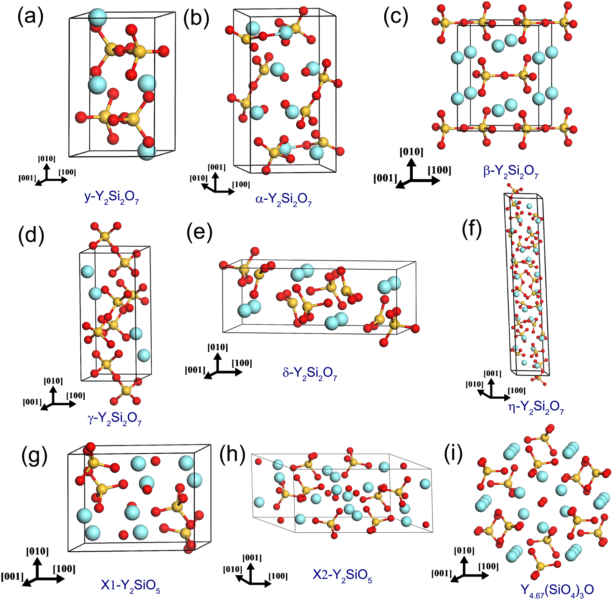
Crystal structure of a y-Y2Si2O7, b a-Y2Si2O7, c b-Y2Si2O7, d g-Y2Si2O7, e d-Y2Si2O7, f h-Y2Si2O7, g X1-Y2Si2O5, h X2-Y2Si2O5 and i Y4.67(SiO4)3O according to the parameters listed in Table 4
Crystal structure and atomic positions of Y–Si–O oxides
Crystal structure of ζ-Y2Si2O7
In 2006, Hartenbach et al. 20 occasionally obtained colourless, lath-shaped single-crystals of Y2Si2O7 with the new ζ-type structure as a minor by-product during the preparation of yttrium oxotellurates (IV) using Y2O3 and TeO2 as starting materials in YCl3 flux after heating at 900°C for 8 days. This polymorph crystallises in space group P21/m with unit cell parameters of a = 5·036 Å, b = 8·065 Å, c = 7·327 Å, and β = 108·6°. The crystallographically unique Y3+ cation is coordinated by seven oxygen atoms arranged in the shape of a slightly distorted monocapped octahedron, and the Y–O bond lengths vary between 2·21–2·48 Å. The isolated oxodisilicate units [Si2O7]6− consist of two Si4+ cations and seven O2− anions, with Si–O bond lengths of 1·61–1·68 Å, Si–O–Si angle of 156°, and O–Si–O angles in the range 91–117°. These pyroanions exhibit an almost perfectly eclipsed conformation, consisting of a horseshoe-shaped backbone with two silicon atoms and three of the oxygen atoms situated on the mirror planes of the unit cell. The remaining four oxygen anions complete this [Si2O7]6− entity of two vertex-sharing [SiO4]4− tetrahedra as terminal ligands for silicon.
Heward et al. 116 pointed out, however, that the structure of ζ-Y2Si2O7 20 was similar to the formerly reported y-Y2Si2O7 (ICSD card No. 28004), except that the monoclinic a- and c-axes were switched, which resulted in different β angles. Compared to the structure described in ICSD card No. 28004, where two non-equivalent Y positions were reported for y-Y2Si2O7, the structure of Hartenbach et al. can fit the experimental XRD pattern of y-Y2Si2O7 much better. There is an un-fittable low angle XRD peak around 16·5° in the work of Becerro et al. 35,38,124 when the crystal structure data of ICSD card No.28004 was used, but it can be successfully fitted by employing the structure of ζ-Y2Si2O7 to refine the XRD pattern of y-Y2Si2O7. The crystal structure in Table 4 provided by Hartenbach et al. 20 for ζ-Y2Si2O7 also coincides well with that on y-Y2Si2O7 provided by Heward et al. 116 Therefore, based on the work of Heward et al., it is concluded that the ‘ζ-Y2Si2O7’ is actually ‘y-Y2Si2O7’ instead of a new type of polymorph of yttrium disilicate.
Crystal structure of η-Y2Si2O7
In 2007, Kahlenberg et al. 21 reported another new type of polymorph η-Y2Si2O7, which was obtained as a by-product in the synthesis of NaYSi2O6 in a high-P/high-T experiment performed on the Na2O–Y2O3–SiO2 system and quenched from 6·0 GPa/1350°C. The crystallographic data are: space group P1¯, a = 6·6290 Å, b = 6·5840 Å, c = 35·916 Å, α = 91·1°, β = 94·5°, γ = 91·7°, V = 1561·6 Å3 and ρ = 4·415 g cm−3. This structure belongs to the group of mixed anion silicates containing isolated [SiO4]-tetrahedra and [Si3O10]-trimers in the ratio of 1:1. The silicate anions are located in layers parallel to (11¯3). Linkage between the layers is provided by six- and eight-fold coordinated Y cations sandwiched between the sheets. The structure can be principally regarded as a two-fold superstructure of the L-type. The Si–Si–Si angles within the three trimers of the asymmetric unit vary between 145·75° and 156·11°. The Si–O distance and O–Si–O angles for SiO4 tetrahedra are in the range of 1·579–1·739 Å and 95·8–119·5°, respectively, implying that the tetrahedral are considerably distorted. Figure 6f is the crystal structure of η-Y2Si2O7 built from the data provided by Kahlenberg et al. 21
Crystal structure of Y4·67(SiO4)3O
Y4·67(SiO4)3O apatite is frequently detected in the preparation of Y2SiO5 and Y2Si2O7 as a second phase. Single-phase Y4·67(SiO4)3O cannot be obtained by conventional preparation methods, however, since it can only be stabilised by other cationic ions such as Fe3+, Al3+, etc. 34 Figure 6i presents the crystal structure of Y4·67(SiO4)3O. Within the finite 1×1×3 supercell, two yttrium vacancies are formed in 4f (1/3, 2/3, 0) sites in the Wyckoff notation that feature three-fold symmetry. Owing to the difficulty in the synthesis of single-phase apatite, no further information on the atomic coordinates and the numbers of crystallographic equivalent Y and Si sites can be found to date. Recently, the apatite structure has been found to be promising in solid oxide fuel cells (SOFC) as a low-cost electrolyte, 127,128 which means that Y4·67(SiO4)3O apatite may be used as a new generation SOFC material.
Defects in Y2SiO5
Pang et al. 51 studied the defects in Y2SiO5 crystals using γ-irradiation. The as-grown and annealed Y2SiO5 samples were irradiated by γ-rays at room temperature. The air-annealed sample and the as-grown sample remained colourless after irradiation, while the H2-annealed sample became grey after irradiation. The absorption spectrum showed that the colour centre formed in the H2-annealed sample after γ-ray irradiation was the F(Vo+2e) colour centre. When γ-photons pass through, they interact with the atoms to produce secondary electrons, and then the oxygen vacancies in the lattice trap one or two electrons and form F-type colour centres. During the air annealing, oxygen diffuses into the lattice and decreases the concentration of oxygen vacancies, so the concentration of F-type colour centres is low, and there is no obvious colour change before and after irradiation.
The defects in Ce3+ doped Y2SiO5 were reported by Aitasalo et al. 64 They demonstrated the formation of oxygen vacancies in Y2SiO5 at reducing preparation conditions, and the formation of F-type colour centres (positive F+ and neutral F centres) by the interaction between oxygen vacancies and electrons. Usually, the lattice energies in oxides are very high, so the charge is imbalanced. The silicate host favours the creation of more F centres than F+ centres.
Recently, Liu et al investigated the formation mechanism of mono-vacancy and native point defects in Y2SiO5 and Y2Si2O7 by first-principles calculations. 129,130 It was found that the formation of native point defects follows the same trend in Y2SiO5 and Y2Si2O7: the Frenkel defect of O is predominant, accompanied by low concentrations of cation antisite defects and Schottky defects. When chemical potential is considered, Oi or VO shows the lowest formation energy under O-rich or O-poor conditions, respectively. In addition, it is possible to control the concentrations of defects by tailoring the chemical potentials of O, Y, and Si. Nonstoichiometry in Y2SiO5 or Y2Si2O7, such as Y2O3 or SiO2 excess, brings out different mechanisms of native point defects or impurity phases. For Y2SiO5, SiY antisite, Oi interstitial, and VY vacancy defects are the main point defects, together with the formation of Y2Si2O7 impurity phase when SiO2 is in excess; while YSi antisites appear together with Yi interstitial and/or VO vacancy defects for excess Y2O3. For Y2Si2O7, the formation of SiY antisites accompanied by Oi interstitial and/or VY vacancy defects are preferred when SiO2 is excess; but the YSi antisite, VO vacancy, and/or Yi interstitial defects dominate the point defects, together with the formation of the Y2SiO5, when Y2O3 is excess. 130 The theoretical calculations also reveal that the self-diffusion of oxygen vacancies has a high-energy barrier in Y2SiO5, which is comparable to those in SiO2 and Al2O3, demonstrating the low oxygen permeability in Y2SiO5. 129
Microstructure characteristics
MacLaren et al. 45,131 observed the microstructure of a hot pressed γ-Y2Si2O7 via high resolution transmission electron microscopy (HRTEM). Stacking faults were frequently identified on (010) planes with g = 040. Lin et al. 132 investigated the microstructure of γ-Y2Si2O7 after indentation. The results revealed a stress-induced amorphisation process under severe mechanical conditions, where the crystalline to amorphous transformation is mediated by slip bands containing a high density of dislocations. The microstructure of Y2SiO5 after spherical indentation was observed by Sun et al., 59 where they found that the grains in the deformation zone were commonly microcleaved into a number of well-orientated subgrains, suggesting that microcleavage is likely to be the major mechanism of energy dispersion upon mechanical damage. Abundant stacking faults and twins were further identified in the subgrains. It is interesting that the twins that are present in the subgrains are (100) twins along the [31¯1¯] shear direction, which have been determined to be the most common ones by far among the deformed grains of LaPO4. 133
Properties of Y–Si–O oxides
Theoretical prediction of the properties of Y–Si–O oxides
Theoretical predictions of the mechanical properties of γ-Y2Si2O7
The theoretical mechanical properties and atomistic shear deformation mechanisms of γ-Y2Si2O7 were investigated using first-principles calculations by Wang et al. 123 Table 5 lists the calculated second-order elastic constants of γ-Y2Si2O7, together with those of α-SiO2 for comparison. 123 The elastic moduli representing stiffness against uniaxial strains, c 11, c 22, and c 33 values of γ-Y2Si2O7 are much higher than c 44, c 55 and c 66 values, which correspond to the resistance to shear deformation. Table 5 also presents the calculated bulk modulus B, shear modulus G, and anisotropic Young’s moduli E of γ-Y2Si2O7. 123 γ-Y2Si2O7 shows 4·3 times and 2·1 times higher B (150 GPa) and G (77 GPa) than those of α-SiO2, respectively. In addition, the Young’s moduli of γ-Y2Si2O7 vary between 113 and 197 GPa, which are 1·3–2·2 times higher than those of α-SiO2. Most interestingly, γ-Y2Si2O7 exhibits low shear deformation resistance, which can be simply calculated from the ratio of shear to bulk modulus G/B. 123,134–139 The ratio of G/B is 0·51 for γ-Y2Si2O7, indicating that it is a damage tolerant ceramic.
Theoretical second-order elastic coefficients of γ-Y2Si2O7 and α-SiO2 123
The ductility of a ceramic is dominated by competition between cleavage and shear slip. If shear slip is activated more easily than cleavage, a ceramic may show intrinsic ductility. 123,134–139 Wang et al. 123 investigated the theoretical deformation modes by straining the unit cell along selected paths and studying the responses of chemical bonds to deformation. The ideal shear strength (12·8 GPa) of γ-Y2Si2O7 is much lower than the ideal tensile strength (19·5 GPa). Based on their model, shear-induced deformation can be easily activated in γ-Y2Si2O7 to generate shear slip, so that the concept of γ-Y2Si2O7 ‘intrinsic ductility’ is thus endorsed. In the atomic deformation mechanism, the YO6 octahedra are loosely bonded and readily accommodate strain on experiencing structural distortion, while the rigid Si2O7 pyrosilicates are resistant to applied shear strain. These weakly bonded YO6 octahedra in the crystal structure of γ-Y2Si2O7 line up to form a series of weakly bonded atomic interfaces and thus allow cleavage along certain atomic surfaces. The proposed shear deformation mechanism is similar to those of other ‘quasi-ductile’ ceramics such as LaPO4 monazite, 135 layered ternary carbides, and nitrides (MAX-phases). 136–139
Theoretical predictions of optical and dielectric properties of γ-Y2Si2O7 and Y2SiO5
The interband optical transitions with all dipole matrix elements for γ-Y2Si2O7 and Y2SiO5 were calculated by Ching et al. 121,122 The imaginary parts of the dielectric functions (ϵ2(ω)) were calculated first and the real parts (ϵ1(ω)) were obtained from the imaginary parts by the Kramers–Kronig conversion. The calculated optical dielectric constant ϵ0 = ϵ1 (ħω = 0) for Y2Si2O7 and Y2SiO5 is 3·11 and 3·44, respectively. ϵ0 can be related to the measured refractive index through n = √ϵ0, and the refractive index for these two crystals is about 1·76 and 1·85, respectively. The low dielectric constants of yttrium silicates suggest promising applications of these materials in the semiconductor industry to replace SiO2.
Mechanical properties of Y–Si–O oxides
Mechanical properties of γ-Y2Si2O7
The mechanical properties of bulk γ-Y2Si2O7 were measured by Sun et al., 58 as summarised in Table 6, together with those of mica-glass ceramic (Macor), 140 LaPO4 monazite, 141,142 and two end materials SiO2 143 and Y2O3. 144 It is noteworthy that γ-Y2Si2O7 has some close mechanical properties to Y2O3, but they are superior to those of machinable Macor and LaPO4, and most importantly, are not just the weighted average of the two end members SiO2 and Y2O3.
Sun et al. observed the presence of local energy dissipation capacity around the Vickers indentations, as well as the non-catastrophic compression fracture mode, and the ‘layered structure feature’ on the fracture surfaces of γ-Y2Si2O7, as shown in Fig. 7a–b , which demonstrates that this ceramic possesses good damage tolerance, similar to those of LaPO4 and Macor. 58 Figure 7c presents a high magnification micrograph of a typical fracture surface of γ-Y2Si2O7 that features many layered steps or cleavage characteristics, which were caused by crack deflection during penetration inside the grains, proving the existence of ‘weak interfaces’ within the crystal structures. When the crack propagation direction is parallel to the weak interfaces, cleavage occurs along the weak planes, or it is deflected across the grains, and thus the energy is consumed. Figure 7d presents the residual three-point bending strength as a function of Vickers indentation load, in which the slope was less than −1/3, indicating that γ-Y2Si2O7 is a damage tolerant ceramic. 145
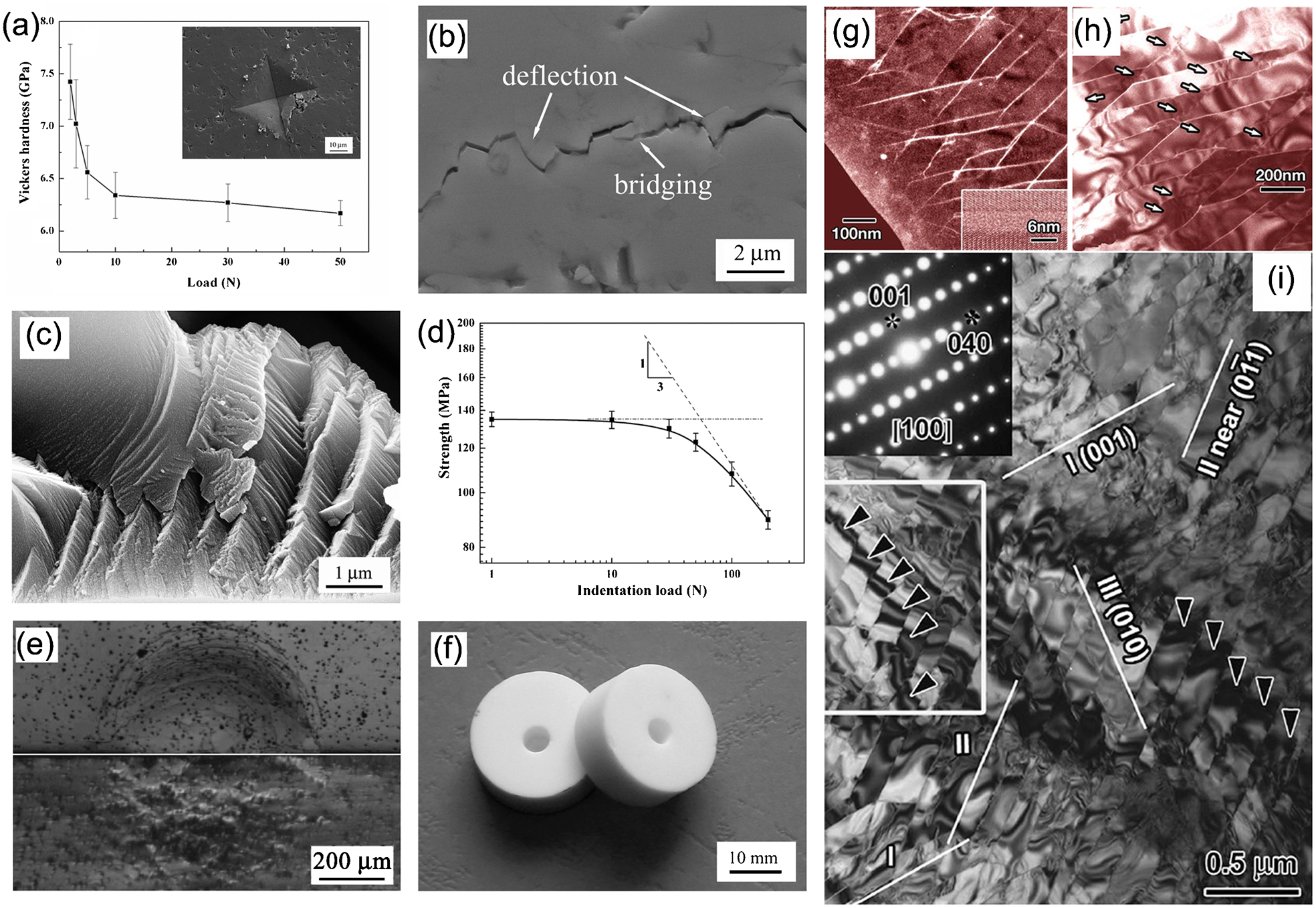
a Microhardness versus indentation load and a SEM image of a crack propagation path (inset) for γ-Y2Si2O7; b high magnification micrograph of a crack produced by microindentation at 30 N; c high magnification micrograph of typical cleavage surface feature of γ-Y2Si2O7; d residual three-point bending strength as a function of Vickers indentation load; e half-surface (upper) and side section (lower) views of Hertzian contact damage for γ-Y2Si2O7 at a load of 900 N or an indentation pressure of 3·6 GPa; f optical image of γ-Y2Si2O7 samples after drilling by carbide tools; g–i transmission electron microscope (TEM) images different magnifications of γ-Y2Si2O7 on the deformation zone under Hertz indentation, showing the distribution of amorphous bands in the inner volume in contact with the indenter, while the bottom-right inset of g is an high resolution TEM (HRTEM) image of the amorphous band parallel to (001), showing the crystal potential projected along 100 and separated by a band with a periodic signal about 6 nm wide (inset of g) 58,132
A permanent impression after Hertzian indentation (Fig. 7e
),
58
which is confined in a well-defined hemispherical contact without brittle conical cracks, was left at the contact site. Within the impression, a series of shear faults were observed. In the cross-sectional image, the damage pattern resembles the continuous plastic zones in the subsurface of slip-line fields beneath indentations. The permanent plastic deformation and shear-dominated faults demonstrates the ‘quasi-plastic’ nature of γ-Y2Si2O7.
146
Lin et al. observed the deformation zone of γ-Y2Si2O7 after Hertzian indentation via HRTEM.
132
The volume directly beneath the indent comprises nanometre-sized grains delaminated by an amorphous phase layer, while dislocations dominate in the periphery, either as dense slip bands in the border of the indent or, further away, as individual dislocations. As shown in Fig. 7g–i
, the deformation centre zone consists of regular lozenge-shaped crystalline cells coexisting with slightly elongated ones, and all these crystalline cells are surrounded by amorphous bands ∼6 nm in thickness that lie along the (001), (010), 


Mechanical properties of X2-Y2SiO5
Although a number of experiments have been carried out on coating X2-Y2SiO5 on C/C composites, 82–99 systematic work has seldom been conducted on the thermal and mechanical properties of Y2SiO5.
The mechanical properties of X2-Y2SiO5 are listed in Table 6. X2-Y2SiO5 shows close mechanical properties to those of γ-Y2Si2O7 and LaPO4. Y2SiO5 has lower hardness and a lower shear modulus, however, than γ-Y2Si2O7 and LaPO4, but higher fracture toughness than LaPO4. The resemblance of Y2SiO5 to γ-Y2Si2O7 and LaPO4 with respect to mechanical properties suggests that Y2SiO5 also possesses lower shear deformation resistance and good machinability. 58,59 It should also be noted that Y2SiO5 has low Young’s modulus (124 GPa), but not as low as 20 GPa as reported by Kondo et al. 56
According to its crystal structure, the weaker Y–O bonds in Y2SiO5 respond to mechanical perturbations more significantly than the strong Si–O bonds. When damage occurs, bond breaking mainly takes place at Y–O bonds along some particular weak planes, while the rigid SiO4 tetrahedra tend to release the energy by rotation.
59
Figure 8a
reveals that the grains in the deformation zone are commonly microcleaved into a number of well-orientated subgrains, suggesting that microcleavage is the major mechanism of energy dispersion upon mechanical damage. The HRTEM image (Fig. 8b
) shows that stacking faults and twins exist in the subgrains.
59
The upper-right HRTEM fringes in Fig. 8b
presents a (100) twin along the 

a Grains in the deformation zone of Y2SiO5 after Hertz indentation, and b high resolution transmission electron microscopy (HRTEM) image of the deformed grains; the upper-right HRTEM pattern presents a (100) twin along the
Thermal properties of Y–Si–O oxides
Recently, some papers have focussed on the application of yttrium silicates as EBCs, and reports on them for high-κ thin films were published. 93,96,100–102 The knowledge of some key thermal properties of Y–Si–O ceramics, however, was lacking for a long time, because of the difficulties in the synthesis and sintering of single-phase Y–Si–O ceramics. The TECs of Y2Si2O7 and Y2SiO5 vary over a wide range in literature [(2·2–4·6)×10−6 K−1 for γ-Y2Si2O7 and (3·1–19)×10−6 K−1 for Y2SiO5]. 41,60,61,83,109,113,114,127,149,150 The misuse of TECs for coating design resulted in severe cracking and spalling of the coatings during tests. 41,82–84
Thermal properties of Y2Si2O7
Thermal expansion of Y2Si2O7
Table 7 lists the TEC of Y2Si2O7, obtained by monitoring the variation of the unit cell as a function of temperature via high-temperature XRD and by directly measuring the length change with temperature via a dilatometer. 60,3,109,117 Dolan et al. 117 reported the TECs of some Y2Si2O7 polymorphs (α, β, γ, and δ-Y2Si2O7) obtained by the XRD powder diffraction method. The TECs are only around 4·0×10−6 K−1 for β- and γ-Y2Si2O7, while those for α- and δ-Y2Si2O7 are around 8·0×10−6 K−1. The reported linear TEC of γ-Y2Si2O7 by Fukuda and Matsubara 109 was (2·2–3·8)×10−6 K−1 in the range of 504–1473 K. The volume TEC of γ-Y2Si2O7 reported by Sun et al. 60 was 6·68×10−6 K−1. Figure 9a shows the temperature-dependent XRD patterns of γ-Y2Si2O7, and Fig. 9b presents the change in the unit cell parameters with temperature from 300 to 1373 K. 39 No phase transformation appeared in the heating process.
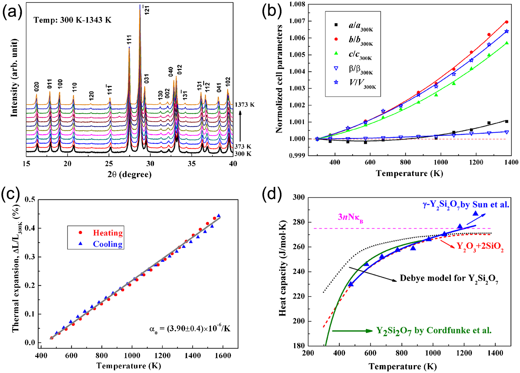
a Temperature-dependent X-ray diffraction (XRD) patterns of γ-Y2Si2O7, and b change of the unit cell parameters with temperature in the temperature range from 300 to 1373 K; c linear thermal expansion behaviour of polycrystalline γ-Y2Si2O7 measured by push-rod dilatometer; and d temperature dependence of the heat capacity for γ-Y2Si2O7 60
Reported thermal expansion coefficients (TECs) for Y2Si2O7 and Y2SiO5
TD: theoretical density
The TEC of polycrystalline Y2Si2O7 was reported by Aparicio and Duran 83 and Sun et al. 60 using a high-temperature dilatometer. The sample that was used by Aparicio and Duran was a polycrystalline bulk Y2Si2O7 with a relative density of 54·5% (2·2 g cm−3). The reported linear TEC of the porous γ-Y2Si2O7 by Aparicio and Duran was 4·6×10−6 K−1. 83 Sun et al. reported the linear thermal expansion behaviour of polycrystalline γ-Y2Si2O7 up to 1300°C, measured by a push-rod dilatometer on a single-phase γ-Y2Si2O7 bulk sample with a relative density of 97% (Fig. 9c ). 60 The average linear TEC is (3·90±0·4)×10−6 K−1, which is quite close to that reported by Dolan et al. 117
Heat capacity of Y2Si2O7
Cordfunke et al. 151 and Sun et al. 60 measured the heat capacity of Y2Si2O7 by the drop-calorimetry and laser-flash methods, respectively (Fig. 9d ). The temperature-dependent heat capacity of Y2Si2O7 is C p = 250·5+24·6×10−3 T−72·64×105 T −2. 60 The experimental heat capacity data 60,151 agreed well with the heat capacity derived from the summation of the heat capacities of Y2O3+2SiO2. 152 The calculated temperature-independent heat capacity of Y2Si2O7 is about 275 J mol−1 K−1
Thermal conductivity of Y2Si2O7
The temperature-dependent thermal conductivity of Y2Si2O7 is κ = 1·039+1162T −1. 60 Clarke and Phillpot 153,154 proposed a method to calculate the minimum thermal conductivity of a material and used it to choose suitable materials for ETBC application, as shown in Table 8. It is clearly shown that γ-Y2Si2O7 has a low minimum thermal conductivity of 1·35 W m−1 K−1, suggesting that it is a promising candidate for EBC/thermal barrier coating (TBC) applications.
Thermal shock resistance of Y2Si2O7
Sun et al. 60 investigated the thermal shock resistance of γ-Y2Si2O7 by the water quenching method and calculated the theoretical thermal shock resistance parameters R, R' and R''' according to Refs. 155 and 156 (Table 9). The experimental R value, the critical temperature difference (ΔT c) in water quenching, was 300 K for γ-Y2Si2O7. 60 Based on Table 9, γ-Y2Si2O7 has a good thermal shock resistance among the various oxide ceramics, according to either the calculated thermal shock resistance parameters or the experimental R value.
Thermal shock resistances R, R' and R''' for γ-Y2Si2O7 and some selected ceramics 60
Thermal properties of Y2SiO5
Thermal expansion coefficient of Y2SiO5
The measured TECs of Y2SiO5 show a wide deviation from author to author, as shown in Table 7. O’Bryan et al. 149 measured the thermal expansion of single-crystal Y2SiO5 in the principal crystallographic direction and the two orthogonal directions on the (010) plane in the temperature range of 298–973 K using a dilatometer. Anisotropic TECs ranged from 0·6×10−6 K−1 in the [100] direction to 11·4×10−6 K−1 in the [001], and the volume TEC of 17×10−6 K−1 were given. The anisotropic thermal expansion of Y2SiO5 was also reported by Nowok et al. 113 and Fukuda and Matsubara 114 using high-temperature XRD. During the measurement, a phase transition from X1- to X2-Y2SiO5 at 1123 K was observed by Nowok et al., 113 and the measured TEC of X2-Y2SiO5 is much larger than that of X1-Y2SiO5, as shown in Table 7. The TECs along the b- and c-axes reported by Nowok et al. and O’Bryan et al. are in excellent agreement, however, the TEC of the a-axis shows a large deviation, which may have resulted because the [100] and [001] directions are not parallel to the principal axes of the expansion ellipsoid. Fukuda and Matsubara 114 examined the change in the unit cell dimensions with temperature up to 1273 K for X1-Y2SiO5 and 1473 K for X2-Y2SiO5. The mean linear TEC of X1-Y2SiO5 is higher than that of X2-Y2SiO5. The TEC increased from 5×10⁻⁶ K−1 (394 K) to 8·7×10−6 K−1 (1273 K) for X1-Y2SiO5, and from 5×10⁻⁶ K−1 (394 K) to 7·77×10−6 K−1 (1473 K) for X2-Y2SiO5. The mean linear TEC of bulk Y2SiO5 was also reported by Ogura et al., 41 Aparicio and Duran, 83 Wagner et al. 150 and Sun et al. 61 Possibly because of the presence of impurities or the low density of some samples, the reported TEC data varied from 3·05×10−6 K−1 to 6·9×10−6 K−1. 41,83,150 Sun et al. measured the TEC on a single-phase polycrystalline X2-Y2SiO5 sample with a relative density of 98%. The TEC of 8·36×10−6 K−1 61 is much larger than the previously reported data. Obviously, the big difference in the TECs of the Y2SiO5 and the SiC substrate resulted in a large thermal mismatch and finally, the failure of the Y2SiO5 coatings.
Heat capacity, thermal diffusivity and thermal conductivity of Y2SiO5
The temperature dependence of the heat capacity, thermal diffusivity, and thermal conductivity of Y2SiO5 was reported by Sun et al. 61 The temperature-dependent heat capacity of X2-Y2SiO5 obeys the relationship C p = 177·48+29·68×10−3 T−59·2×105 T −2. The molar heat capacities extrapolated from this relationship are 120 J mol−1 K−1 at room temperature (300 K) and 215 J mol−1 K−1 at high temperature (1400 K). Thermal diffusivity of Y2SiO5 can be fitted by a second-order polynomial equation, as D th = 0·01124−1·314×10−5 T+6·331×10−9 T 2. The thermal conductivity of Y2SiO5 has an inverse proportional relationship with temperature: κ = 1·138−216·2T −1. The extrapolated thermal conductivity of Y2SiO5 is 1·86 and 1·29 W m−1 K−1, respectively, at 300 K and 1400 K.
Therefore, Y2SiO5 has a much lower thermal conductivity than the most commonly used TBC materials. 140,160,161 Figure 10a displays the thermal conductivities of some TBC materials as a function of temperature. 60,61 The thermal conductivity of a dense Y2SiO5 is only slightly higher than those of an air plasma-sprayed 7 mol.-% yttria stabilised zirconia (APS 7YSZ) coating and monoclinic zirconia. 140 Figure 10b presents the TECs of some coating materials and nickel based superalloys versus thermal conductivity. 61 According to Fig. 10b , Y2SiO5 can be selected as a coating material for nickel based superalloys, if only the thermal expansion and thermal conductivity are considered. Moreover, Y2SiO5 is also an excellent environmental barrier coating on top of YSZ TBC layer.
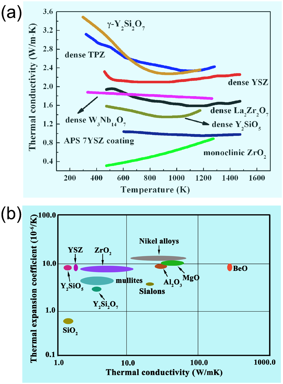
a Thermal conductivities of some selected thermal barrier coating (TBC) materials as a function of temperature, and b thermal expansion coefficient (TEC) as a function of thermal conductivity for some coating materials and nickel based superalloys 61
Tribological properties of Y–Si–O oxides
Tribological properties of γ-Y2Si2O7
Ceramics are candidates for wear-resistance applications especially under severe environmental conditions. 162 Thus, wear characteristics in different environments need to be well understood. Sun et al. 163 investigated reciprocating ball-on-flat dry sliding friction and wear behaviour of γ-Y2Si2O7 ceramic flats in contact with AISI 52100 bearing steel and Si3N4 balls at 5–15 N normal loads in the ambient environment. The kinetic friction coefficients (COFs) of γ-Y2Si2O7 varied between 0·53 and 0·63 against AISI 52100 steel, and between 0·51 and 0·56 against Si3N4. The wear rates of γ-Y2Si2O7 were on the order of 10−4 mm3 (N−1 m−1). Wear occurred predominantly during the running-in period and almost ceased at the steady friction stage. The wear debris played an important role in the steady friction stage. When against AISI 52100 bearing steel, a thick transfer layer was left both in the worn tracks of the flats and in the contact surfaces of the counterpart balls, owning to the high chemical affinity between γ-Y2Si2O7 and the AISI 52100 balls. In contrast, the worn surfaces rubbed by Si3N4 were much smoother, the asperities on the surface were removed, and the worn tracks were all covered with a continuous dense debris layer. The brittle microfracture of γ-Y2Si2O7 grains at the running-in stage is the major mechanism. The adhesion wear and tribochemical wear are the major mechanisms responsible at the steady friction stage. The severe running-in wear indicates that the strengthening of γ-Y2Si2O7 is beneficial for wear applications.
Tribological properties of γ-Y2Si2O7/ZrO2 composites
To improve the mechanical and tribological properties of γ-Y2Si2O7, Sun et al. 164 developed a series of Y2Si2O7/ZrO2 composites, which are promising as protective coatings against thermal loads and chemical attack. 165 Compared to γ-Y2Si2O7, γ-Y2Si2O7/ZrO2 composites showed improved mechanical properties, e.g. the Young’s modulus was enhanced from 155 to 188 GPa (121%), and the flexural strength from 135 to 254 MPa (181%), when 50 vol.-% ZrO2 was incorporated.
The COFs of the Y2Si2O7/ZrO2 composites against Si3N4 balls vary in the range of 0·49–0·59 under 5 N but vary in a narrow range of 0·69–0·76 under 15 N. The wear rates of the composites against Si3N4 balls were independent of ZrO2 content under low-load conditions; but decreased from 7·53±0·25 mm3 N−1 m−1 for the Y2Si2O7–10 vol.-% ZrO2 composite to (0·64±0·21)×10−4 mm3 N−1 m−1 for the Y2Si2O7–50 vol.-% ZrO2 composite under 15N.
The composition–mechanical properties–tribology relationships of Y2Si2O7/ZrO2 composites were elucidated by Sun et al. (Fig. 11). 165 The wear resistance of the composites was not only influenced by the applied load, hardness, strength, toughness, and rigidity, but also by the micromechanical stability of the microstructures. To achieve high wear resistance, a compromise between the flexural strength and the fracture toughness should be reached.
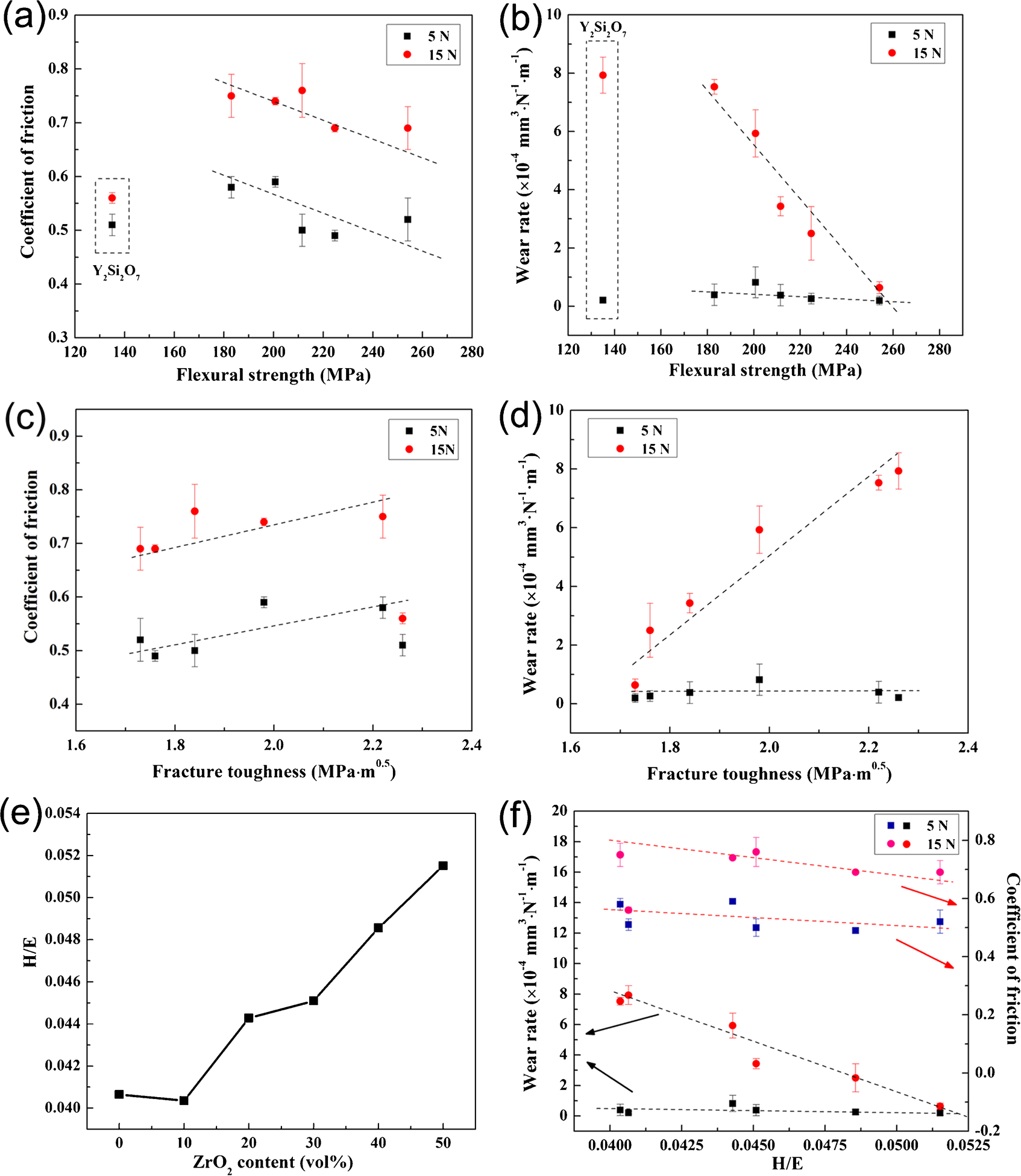
Plots of correlations of tribological properties of the composites with the basic mechanical parameters: a friction coefficients (COF) vs. flexural strength, b wear rate vs. flexural strength; c COF vs. fracture toughness, d wear rate vs. fracture toughness; e the ratio of the hardness to Young’s modulus (H/E) as a function of ZrO2 content for the γ-Y2Si2O7/ZrO2 composites, and f variation of COF and wear rate against H/E 164
Environmental durability of Y–Si–O oxides
Oxygen permeability in Y2SiO5
Ogura et al. 74 measured the oxygen permeability constant through an Y2SiO5 wafer from 1973 to 2033 K. The oxygen permeability was measured in a two-chamber apparatus, in which the upper chamber contained a mixture of argon and oxygen, and the bottom chamber contained high-purity argon. The two chambers imposed an oxygen potential gradient across the test wafer. The detailed theoretical basis of the permeability testing can be found in Ref 74. At 1973 K, the oxygen permeability constant of Y2SiO5 is 10−10 kg m−1 s−1. The activation energy of diffusion, E d, varied between 227 and 349 kJ mol−1, which is close to the energy of vacancy diffusion and much higher than the energy of interstitial diffusion of molecular oxygen. Vacancy diffusion was considered dominant in oxygen transport through Y2SiO5 below 1913 K. On the contrary, interstitial diffusion is dominant above 1913 K.
Argirusis et al 92 also studied the oxygen self-diffusion in Y2SiO5 by the isotope exchange depth profiling method. The single-crystal sample was put into a furnace and equilibrated at the diffusion temperature (1150–1530°C) in a 16O2 atmosphere. Then, the atmosphere was rapidly changed from 16O2 to 18O2. At 1505°C, the oxygen self-diffusion coefficient was determined to be 1·5×10−12 cm2 s−1, and the activation energy was 3·5 eV (∼338 kJ mol−1). This activation energy coincides well with the value reported by Ogura et al. 74 Although the oxygen diffusion coefficient in single-crystal Y2SiO5 is two orders of magnitude higher than that of single-crystal mullite, the oxygen diffusivity of Y2SiO5 is still low enough to render it a good oxidation protection material for SiC–C/C composites. 92
Hot corrosion resistance of Y2Si2O7
Hot corrosion behaviour of γ-Y2Si2O7 in strong basic Na2CO3 molten salt environment
Sun et al. 62 studied the hot corrosion behaviour of γ-Y2Si2O7 in Na2CO3 molten salt at various temperatures (850–1000°C). Compared with Na2SO4, Na2CO3 decomposes more readily to Na2O and CO2, so it is usually used to study the corrosion under strong basic conditions. Almost all silicon-based ceramics are severely corroded in Na2CO3 molten salt due to the dissolution of passive SiO2 thin film in strong basic molten salt. 94,95,166–171 In the hot corrosion of Y2Si2O7 in Na2O melt (since Na2CO3 decomposes into Na2O and CO2 at the test temperatures), it was found that Na2O melt attacked the grain boundaries first and then penetrated into the inner part of the sample to surround the grains and then react with Y2Si2O7. Subsequently, the YO2 − ions that were formed in the melting product would diffuse outwards due to the basicity (or Na2O) gradient between the oxide/salt interface and the salt/gas interface, 170,171 and then precipitate as a layer of non-protective, loose Y2O3 particles at the salt/gas interface. On the other hand, SiO3 2− could not re-precipitate from the melt, since the solubility of SiO2 is independent of Na2O activity under basic conditions, 171 so it is left as Na2O.xSiO2 at the oxide/salt interfaces. Once x = 3·65 was approached in the Na2O.xSiO2 melt, a corrosion-protective silica layer would then precipitate beneath the silicate melt and eventually seal off the inner grains from further corrosion. In general, γ-Y2Si2O7 showed severe corrosion in the extremely strong basic Na2CO3 molten salt. The thicknesses of the corrosion scales were less than 90 μm, however, after 20 h exposure at 1000°C, which is attributable to the formation of a thin layer of protective SiO2 under the Na2O.xSiO2 melt that protects the inner material from further corrosion.
Hot corrosion behaviour of γ-Y2Si2O7 in weak acidic Na2SO4 molten salt environment
According to the hot corrosion theory proposed by Rapp,
171
the oxyanion sodium sulphate melt can be described by an acid-base chemistry in a manner analogous to the pH of aqueous solutions. For pure Na2SO4, 

Water vapour corrosion of Y2Si2O7 and Y2SiO5
The corrosion behaviour of Y2Si2O7 containing Y, Yb, and Lu was investigated by Maier et al. 172 in a gas stream containing water at 1500°C. They found that the facilities for water vapour corrosion testing had a strong influence on the experiments: silica or silica-forming tubing causes high internal P Si(OH)4, which should artificially slow down corrosion rates; and alumina tubing causes alumina contamination via P Al(OH)3, which led to alumina transfer to the test samples. 172 In a similar way to silica, the water vapour corrosion of rare-earth silicates also results in the formation of volatile silicon hydroxide as: Re2Si2O7+2H2O→Re2SiO5+Si(OH)4 (g). 172 Courcot et al. 173 also studied the water vapour induced corrosion of Y2SiO5 and Y2Si2O7 at 1400°C for 300 h under 50 kPa H2O partial pressure. They observed that the volatilisation of both Y(OH)3 and Si(OH)4 owing to the reaction with water during corrosion. The monitored mass change showed that Y2SiO5 had a weight gain, whereas Y2Si2O7 exhibited a weight loss. The difference in weight change was mainly caused by the reaction of Al(OH)3 from the sample holder with Y2SiO5 and Y2Si2O7 to form yttrium aluminium garnet (YAG). Since Y2Si2O7 had a lower reactivity with Al(OH)3 than Y2SiO5, less YAG was detected at the end of the corrosion test and resulted in a weight loss. It was also reported that the preparation methods have an influence on the corrosion resistance. The material synthesised by the sol-gel route was less resistant against corrosion.
Therefore, it seems that the water vapour corrosion on Y2Si2O7 and Y2SiO5 is influenced by many factors, such as the preparation method, heating history, impurity, morphologies, etc., and further investigations are still needed. Moreover, a rapid reaction between yttrium silicates and alumina-containing compounds was observed, indicating that the water vapour corrosion testing system has to be improved, and an environment containing the aluminium element should be avoided for the high-temperature application of yttrium silicates.
Dielectric properties of Y2Si2O7
Cao et al. 174,175 studied the dielectric properties of γ-Y2Si2O7 in the X-band from room temperature to 1400°C. In the measured frequencies (8·0, 9·1, 10·3 and 11·8 GHz), γ-Y2Si2O7 exhibits a low dielectric loss, which is on the order of 10−3 in magnitude. The permittivity maximum and the loss tangent maximum are 5·71 and 8·3×10−3, respectively, in the tested temperature range. There is very weak frequency dependence, but strong temperature dependence of its permittivity. The permittivity increases monotonically with temperature at all investigated frequencies. The strong temperature dependence of the permittivity indicates that γ-Y2Si2O7 may present special polarisation in a microwave field. According to Cao et al, 174,175 this corresponds to a non-Debye relaxation process with a dielectric relaxation time of 10−11 s at 800°C, which is attributed to the movement of thermal-excitation structural defects that are responsible for structural relaxation polarisation.
Structure-property relationships of Y–Si–O oxides
Wang et al. 123 calculated the electronic structure and predicted the mechanical properties of γ-Y2Si2O7. The low shear to bulk modulus ratio and the low ideal shear to tensile strength ratio indicate its low shear deformation resistance and damage tolerance. The Y–O bond is weaker and readily stretches and shrinks, while the Si–O bond is strong and more rigid. The relatively soft YO6 octachedron positively accommodates shear deformation by structural distortion, while the Si2O7 pyrosilicate unit is more resistant to deformation. The unique crystal structure and nature of the chemical bonding of γ-Y2Si2O7 thus lead to the low shear deformation resistance. This kind of deformation mechanism was later proved by experimental mechanical properties evaluation and microstructure characterisation. Figure 12 presents the possible weakly bonded atomic planes in γ-Y2Si2O7 (a–d), the valence electron density isosurface of γ-Y2Si2O7 projected on the (001) plane (e), and the microstructure of γ-Y2Si2O7 after deformation (f). It clearly shows that the inhomogeneous distribution of the chemical bonding in some special planes contributes to the low shear deformation resistance of the mechanical response mode.
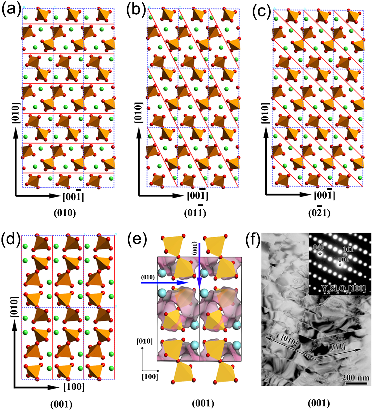
a–d Possible weakly bonded atomic planes in γ-Y2Si2O7, e valence electron density isosurface of γ-Y2Si2O7 projected on the (001) plane, and f microstructure of γ-Y2Si2O7 after deformation 132
Cao et al. 174,175 observed a non-Debye relaxation behaviour different from that of SiO2 when measuring the dielectric properties of γ-Y2Si2O7, which is actually also associated with the crystal structure of γ-Y2Si2O7. With increasing temperature, the Y–O bonds become much weaker, which results in the elongation or rupture of some Y–O bonds, so that the rigid Si2O7 pyrosilicates and Y ions can rotate or move more easily at high temperatures. Since the (100) and (010) planes are the most common weak interfaces, the thermal-excitation atomic groups (rigid Si2O7 pyrosilicates and Y ions) would move easily along the direction of the electric field when either plane is perpendicular to the electric field. The local motions of the thermal-excitation atomic groups, which are actually attributed to the movement of structural defects, would create structural relaxation polarisation in electromagnetic fields.
Sun et al. 59 also observed the same relationship between the crystal structure and mechanical properties in investigating the mechanical properties of X2-Y2SiO5. The crystal structure of Y2SiO5 suggests that the low-energy weakly bonded atomic planes are crossed only by the easily broken Y–O bonds. The weakly bonded Y–O atomic planes as well as the rotationally rigid SiO4 tetrahedra, are the origins of the low shear deformation, good damage tolerance, and easy machinability of Y2SiO5. Transmission electron microscopy observations (Fig. 9) also demonstrate a large number of microcleavages, stacking faults, and twins along these weakly bonded atomic planes, which disperse the strain energy and thus allow ‘ductility’ of Y2SiO5.
Besides the intrinsic crystal structure features, the grain boundaries also exhibit strong influences on the material properties. Up to now, no systematic work has been carried out on the grain boundaries of Y–Si–O oxides. MacLaren et al. 45 carried out TEM observations on hot-pressed Y2Si2O7 ceramic with 3% LiF fluxing additive. They found that the microstructure consisted of large grains of γ-Y2Si2O7 containing rounded glassy Y-doped SiO2 inclusions. At the grain boundaries, excess glassy SiO2-rich material is dominant. The formation of silicon-rich grain boundaries in Y2Si2O7 has a dramatic influence on the performance of this ceramic. Figure 13 shows the Young’s modulus (E) as a function of temperatures in γ-Y2Si2O7, where silicon-rich grain boundaries were detected when excess silica was used for the synthesis. 176 As the temperature increases, the variation of E clearly presents three stages. From room temperature to 600°C (stage I in Fig. 13b ), the elastic modulus is linearly damped owing to the lattice expansion induced change in the atomic bonding force and swelling of the material. From 600 to 800°C (stage II), an abnormal increase in the elastic modulus was observed, which might be caused by the crystallisation of grain boundary silica. When the temperature is above 800°C (stage III), the elastic modulus of Y2Si2O7 dramatically decreases. The fast degradation of stiffness at this stage is likely to be because of the softening of silica grain boundaries. Therefore, the high-temperature mechanical properties of Y2Si2O7 are strongly influenced by the grain boundary silica.
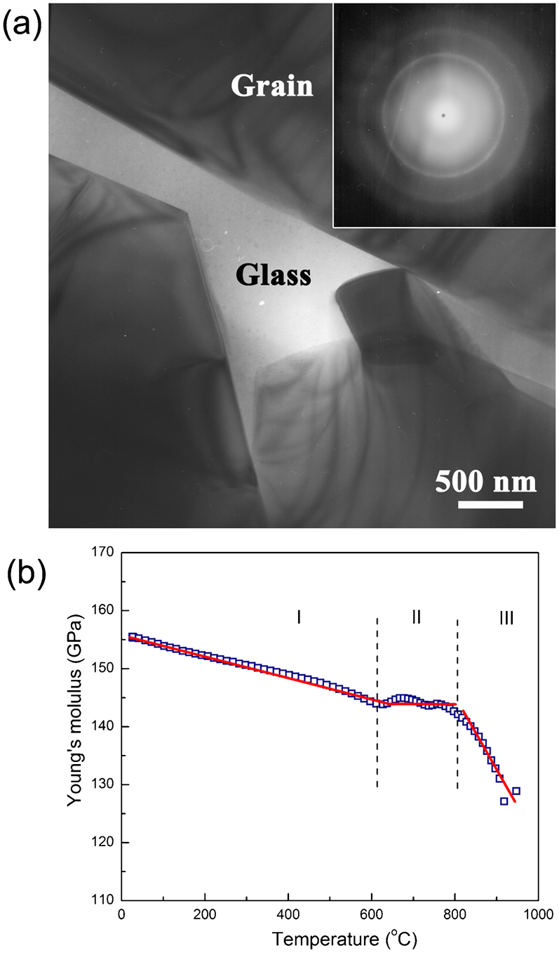
a Transmission electron microscopy (TEM) images of γ-Y2Si2O7 with the inset corresponding selected area electron diffraction (SAED) pattern showing the existence of grain boundary glass phase, and b variation of the Young’s modulus of γ-Y2Si2O7 as a function of temperature 176
During the environmental durability testing of γ-Y2Si2O7, 62,63 the preferential etching of grain boundaries by molten salt was also observed. Without question, the glassy grain boundaries contribute to the rapid corrosion of γ-Y2Si2O7 at the initial stage. In the water vapour corrosion tests, the grain boundaries may also affect the performance, but no related grain boundary characterisation was performed. The optimisation of the grain boundary structure/chemistry of Y–Si–O ceramics may further increase their corrosion resistance.
Potential applications of Y–Si–O oxides
Y–Si–O oxides are refractory with melting points higher than 1775°C. From the mechanical perspective, γ-Y2Si2O7 and Y2SiO5 are readily machinable and can be shaped into complex parts by conventional cemented carbide tools. The low shear deformation resistance implies that γ-Y2Si2O7 and Y2SiO5 are promising materials for complex shape components and weak interfacial phases in fibre-reinforced ceramic-matrix composites. γ-Y2Si2O7 also has good resistance to strong basic Na2CO3 molten salt and weakly acidic Na2SO4 molten salt at temperatures up to 1000°C. Moreover, the critical temperature difference ΔT c of γ-Y2Si2O7 is 300 K, ensuring its tolerance to rapid temperature variations. Recently, Boakye et al. 177 proved the feasibility of using γ-Y2Si2O7 for weakly bonded interfacial phases in SiCf/SiC composites. In their study, Y2Si2O7 was coated on α-SiC and SiC fibre using SiO2/Y(OH)3 sol-gel precursors. The coatings were heat treated at 1400°C for 8 h in argon with 500 ppm oxygen. A mixed γ-Y2Si2O7/β-Y2Si2O7 coating was formed on the SiC fibres demonstrating that it is feasible to coat SiC fibres with oxidation resistant fibre matrix interphases in SiCf/SiC composites (Fig. 14a–d ). Thereafter SiC fibre-reinforced Y2Si2O7 matrix composites were fabricated, and the fibre push-out behaviour was studied. 178 Preliminary results showed that SCS-0 fibres in dense β, γ-Y2Si2O7 matrices debonded and pushed-out with sliding stresses of 15–60 MPa, within the range reported for C, BN, and LaPO4 coatings (Fig. 14e ). Fibres in the α-Y2Si2O7 matrix showed poor and erratic push-out behaviour because of the radial compressive stresses that developed on the fibres as result of the differences in TECs (fibre ∼4 and matrix ∼8).
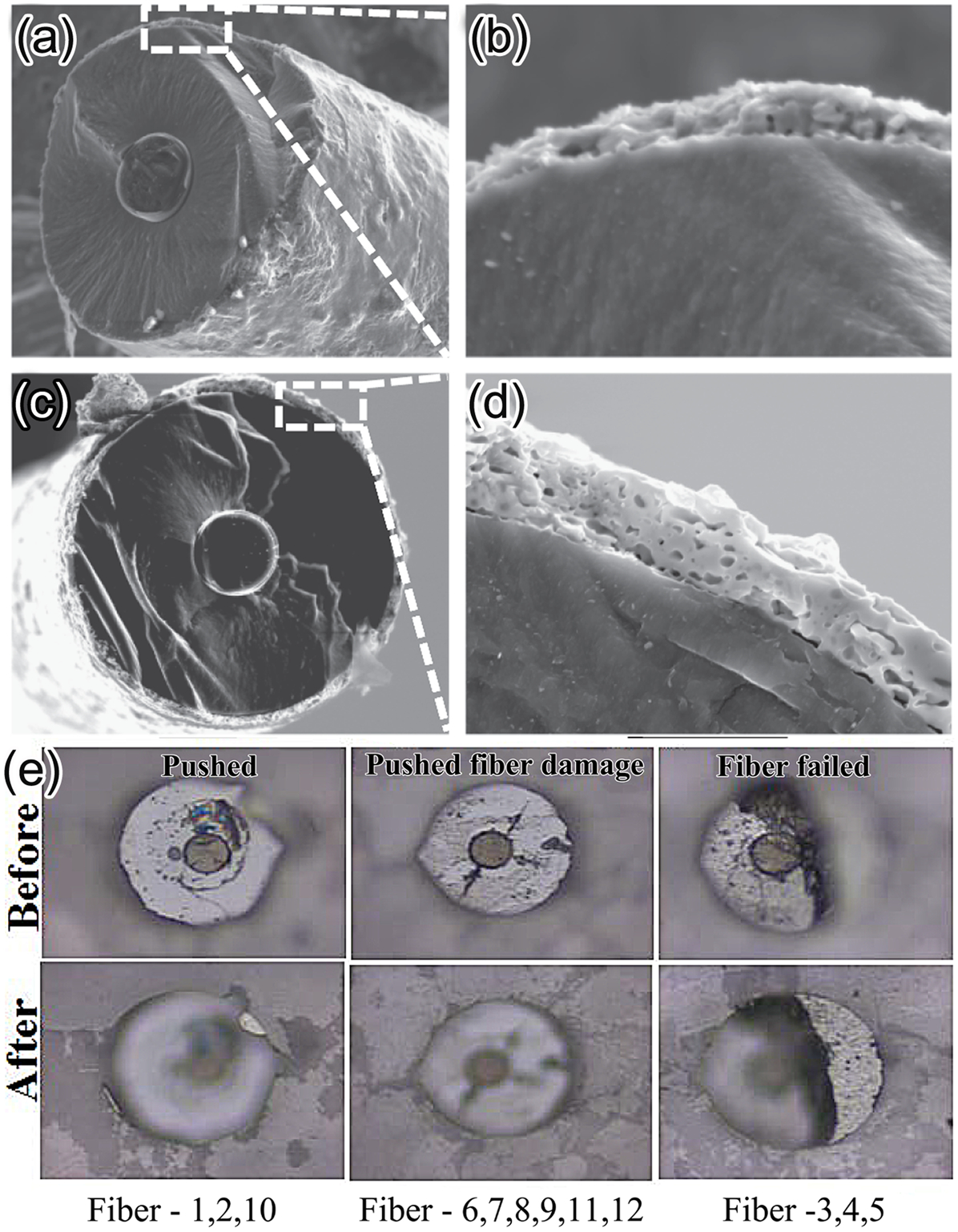
γ-Y2Si2O7 and X2-Y2SiO5 have complementary linear TECs (∼3·9×10−6 K for γ-Y2Si2O7 and 8·36×10−6/K for Y2SiO5) and low thermal conductivity (<3 W m−1 K−1 above 300°C for γ-Y2Si2O7 and ∼1·6 W m−1 K−1 for Y2SiO5). 60,61 The unique thermal properties imply the high competitiveness of γ-Y2Si2O7 and Y2SiO5 used together or separately as candidate materials for environmental/TBC. In particular, γ-Y2Si2O7 can be coated on silicon-based ceramics, owing to its close linear TECs with silicon carbide or silicon nitride. γ-Y2Si2O7 ceramic is also a promising communication window material for the re-entry space shuttles according to Cao et al. 174,175 Therefore, Y–Si–O oxides have promising applications as high-temperature structural ceramics, machinable ceramics, environmental/TBC, and weakly bonded interphases for fibre-reinforced ceramic-matrix composites. Moreover, the defect formation and migration behaviours of Y–Si–O ternary oxides imply the functional potential of yttrium silicates as luminescent materials and solid-state ionic conductors. Y–Si–O oxide with apatite structure might be an especially promising low-cost electrolyte candidate for SOFC.
Conclusions
In this review, the crystal structure, preparation methods, mechanical properties, dielectric properties, and thermal properties, as well as the environmental durability of Y–Si–O ceramics are reviewed from both theoretical and experimental points of view. Some of the polymorphs of Y–Si–O oxides, such as γ-Y2Si2O7 and X2-Y2SiO5, feature high damage tolerance, low shear deformation resistance, good machinability, tunable tribological properties, and excellent environmental durability in hazardous atmospheres. The unique multi-scale structure features ensure promising applications of this family of materials as high-temperature structural components, machinable ceramics, oxidation/thermal/EBCs, and weakly bonded interphases in fibre-reinforced composites, as well as luminescent materials, and solid-state ionic conductors.
Footnotes
Acknowledgements
This work was funded by the National Natural Science Foundation of China (NSFC) under grant Nos. 50802097, 50832008 and the IMR Innovation Research Foundation.