
Abstract
The γ-TiAl alloys are promising high temperature materials for aeroengines due to their low density, high specific strength and low material cost compared with Nickel based superalloys. However, the insufficient ductility at room temperature and the limited oxidation resistance at temperatures above approximately 750°C have limited their applications. Oxidation resistance in the application temperature range of 800 and 1000°C is of particular importance. Remarkable improvement to the environmental resistance by adding ternary and quaternary elements to the γ-TiAl alloys has been reported; however, alloying additions frequently deteriorate their mechanical properties. Surface modifications or coatings, which promote the formation of highly protective alumina scales, are also viable ways to improve the environmental resistance of TiAl alloys. In this article, the research work from the last 30 years on the oxidation behaviour of bare and coated TiAl alloys will be reviewed, with special focus on the γ-TiAl alloys. The review will begin with the oxidation behaviour of TiAl substrate alloys and the oxidation behaviour of γ-TiAl alloys with high temperature coatings such as aluminide, MCrAlY, Ti–Al–X and thermal barrier coating (TBC) system will be followed.
Introduction
Ti-base alloys have played a key role in improving the performance of gas turbine engines since the mid-1950s. 1 However, the upper operating temperature of conventional high-temperature titanium alloys at that time was limited to 600°C 2 and they also suffered from insufficient damage tolerance, creep strength, and fire resistance at high temperatures. Developments of new materials that could overcome those limitations while achieving light weight had been undertaken since the 1980s. The materials most suited to these demands are TiAl-based alloys. 1
In the last few decades, there has been considerable interest in TiAl intermetallics as potential materials for aeroengines, due to their low density, high specific strength compared with nickel-based superalloys. 3 Within the TiAl system, alloys containing 40–50 at.-%Al are called γ-TiAl-based alloys. 4 γ-TiAl alloys are classified into two groups: single-phase (γ) alloys and two-phase (γ+α2) alloys. 1,5 Single-phase alloys are of limited engineering significance because of their poor ductility and fracture toughness. 6 Engineered γ-TiAl alloys are a sub-class of two-phase (γ+α2) alloys, often with some small amounts of dispersed β phase particles. 7 The β phase can be stabilised by the addition of appropriate ternary elements such as Nb and Mo. 8 The volume fractions of the α2 and γ phases depend on the Al content. In the binary phase diagram for Ti and Al, the compositional range of relevant engineering importance is from 45 to 48 at.-%. 9
By using appropriate heat treatment and thermomechanical processing routes, the morphology of the phases can be changed to produce either lamellar or equiaxed microstructures, or a mixture of the two (duplex structure). 1 Four main microstructures are shown in Fig. 1. 10
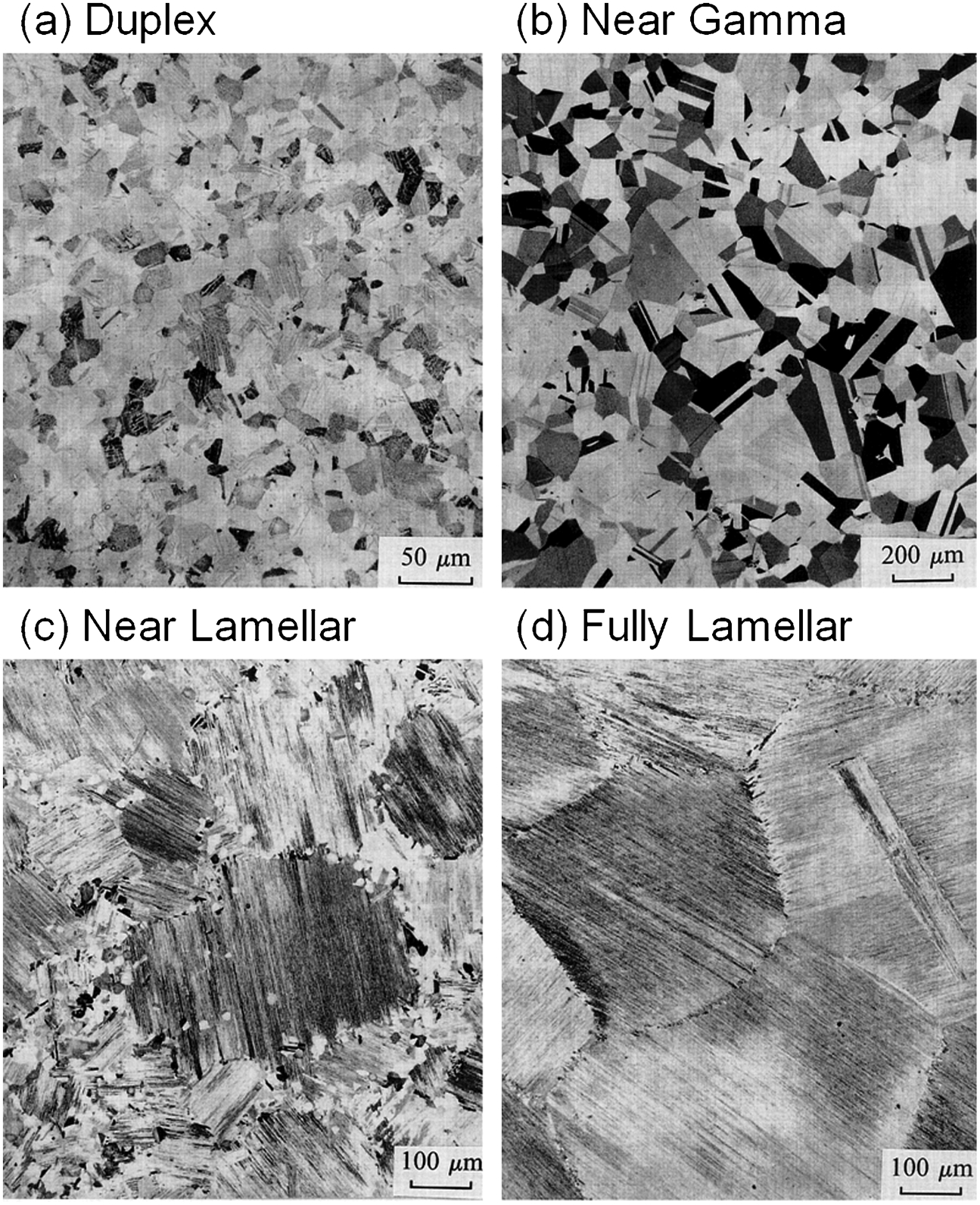
Microstructures of Ti–48 at.-%Al alloy 10
These characteristic microstructures are often termed as duplex (D), near gamma (NG), near lamellar (NL) and fully lamellar (FL). Those microstructures can be developed by heat treatments at specific temperatures 11 illustrated in Fig. 2.
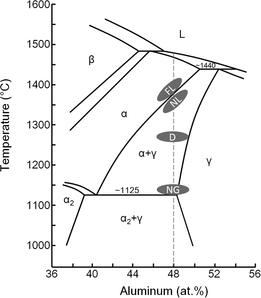
FL: fully lamellar, NL: near lamellar, D: duplex, NG: near gamma 11
The duplex microstructure is composed of equiaxed γ grains mixed with FL grains, roughly of the same volume fraction. 11 The lamellar microstructure consists of alternating α2 and γ lamellae and can be formed by cooling along the path of α→α+γ→α2+γ after heat treating within the single α phase region. 11 The duplex microstructure has good room temperature ductility and strength, but relatively poor creep resistance and fracture toughness. 12 The FL microstructure yields improved creep resistance and fracture toughness compared to the duplex microstructure. 12
Titanium aluminides based on the γ-TiAl phase have proved to be promising high-temperature materials for aeroengine and automotive applications, such as high-pressure compressor blades and vanes, low-pressure turbine blades, turbocharger wheels, and exhaust valves. 13 However, some of their properties still need to be improved, such as insufficient ductility at room temperature and poor oxidation resistance in the envisioned application temperature range between 800 and 1000°C. 14 Activities to enhance the performance of γ-TiAl alloys have focussed on improving room-temperature ductility, strength, and workability, as well as increasing creep and oxidation resistance. γ-TiAl alloy containing 45–46 at.-% aluminium and 5–8 at.-% niobium is one of the most popular alloys which have the properties required for potential applications. 13
Despite the high aluminium content of γ-TiAl alloys, they do not exclusively form protective alumina (Al2O3) scales but build titania (TiO2) as well, which is a fast-growing oxide that does not provide long-term oxidation protection. 15 The poor oxidation resistance at temperatures above approximately 750°C has played a role in preventing these alloys from wider application. 16 A great deal of research has already been conducted to improve oxidation resistance by adding ternary and quaternary elements. 14,17 For example, Nb, Si, W, Cr, or Ta addition to single-phase gamma alloys can provide strength as well as improved oxidation resistance. 1,2,18 Nb, W, Si, Mo, and Ta appeared to improve high-temperature oxidation resistance of TiAl-based alloys, with Nb being the most effective alloying element. 17 Currently, the Nb-containing alloys, Ti–48Al–2(Cr or Mn)–2Nb (at.-%) or TiAl–(Nb, Cr, B, C) (at.-%), exhibit properties required for operating temperatures up to 760°C. 19 Despite the improvement of the oxidation resistance of γ-TiAl alloys by alloying additions, they frequently deteriorate the mechanical properties. 20
Another way to improve the oxidation resistance is by surface modification or addition, which promotes the formation of highly protective alumina scales. It has been reported that pre-oxidation treatment at low oxygen partial pressure, sulphidation pretreatments, pack cementation (PC), ion implantation, as well as protective coatings are effective in improving the oxidation resistance. 20 In general, the protection is accomplished by the formation of a low growth rate oxide on the coating surface, which becomes a diffusion barrier and, in turn, significantly lowers the oxidation kinetics. 14 One major problem of coatings development was that although reasonable oxidation resistance was achieved in many cases, most of these coatings tended to be inherently brittle or formed brittle phases with the substrate material, thus degrading the substrate’s mechanical properties. 2
In this paper, the oxidation behaviour of TiAl alloys with or without protective coatings will be reviewed. Initially, the oxidation behaviour of TiAl alloy itself will be discussed, followed by a discussion of the oxidation behaviour of TiAl alloy with high-temperature coatings such as aluminide, MCrAlY, Ti–Al–X, and thermal barrier coating (TBC) systems.
Oxidation behaviour of TiAl alloy
Oxidation mechanism of TiAl alloy
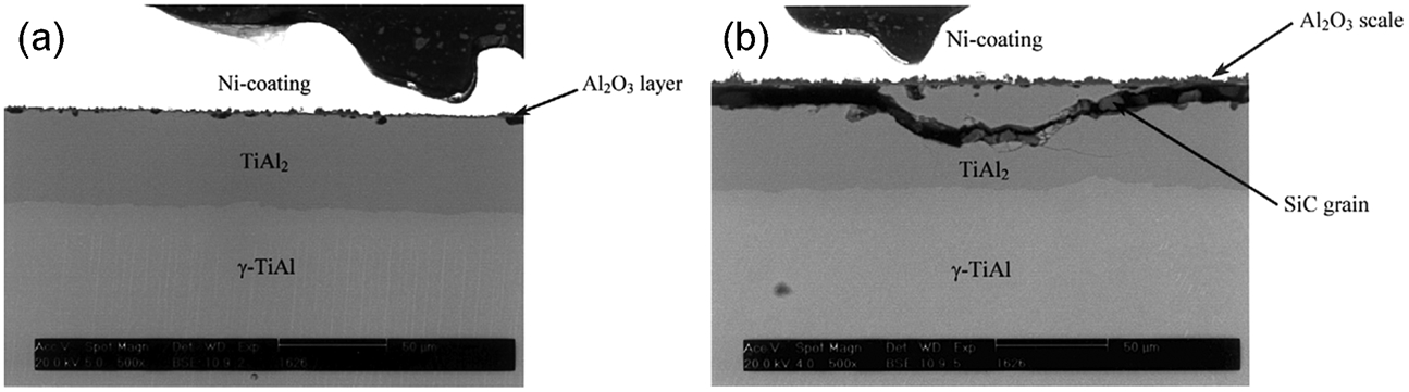
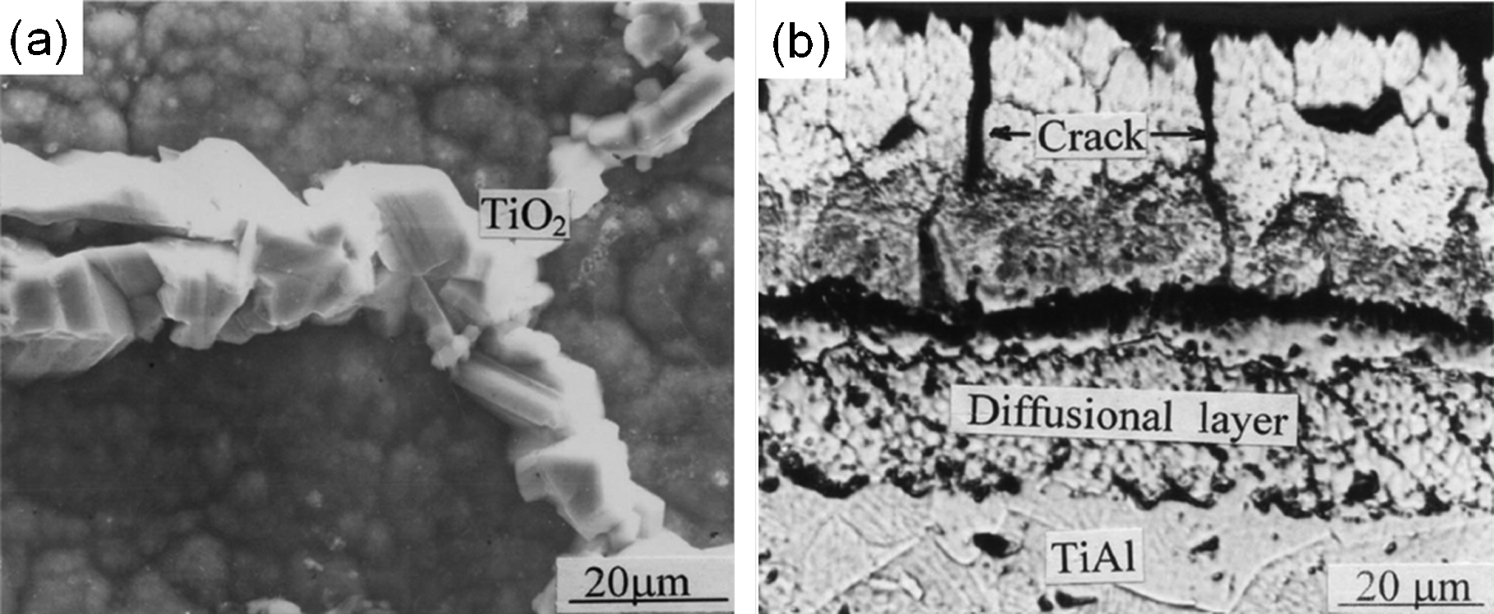
The protection of most materials at elevated service temperature is provided by the formation of Cr2O3, SiO2 or Al2O3 that are slow growing, stable, continuous, and adherent to the substrate. 19,21,22 Unfortunately, it has been reported that protective Al2O3 scales do not form readily when TiAl is exposed to an oxidising atmosphere despite the high aluminium content. 22 For example, the oxidation products of a binary γ-TiAl which was isothermally oxidised in oxygen at 1000°C for 48 h are not only Al2O3 (α-alumina) but also TiO2 (rutile), TiN, Ti2AlN, and α2-Ti3Al. 24 In general, the oxide scale consists of three layers, an outer layer of TiO2 grains, an intermediate layer of Al2O3, and a porous inner layer consisting of TiO2+Al2O3 grains. Figure 3 shows a typical TiO2/Al2O3/Al2O3+TiO2 structure of surface oxides formed on a TiAl–4Nb–3Mn (at.-%) TiAl alloy after isothermal exposure at 900°C for 192 h in air.
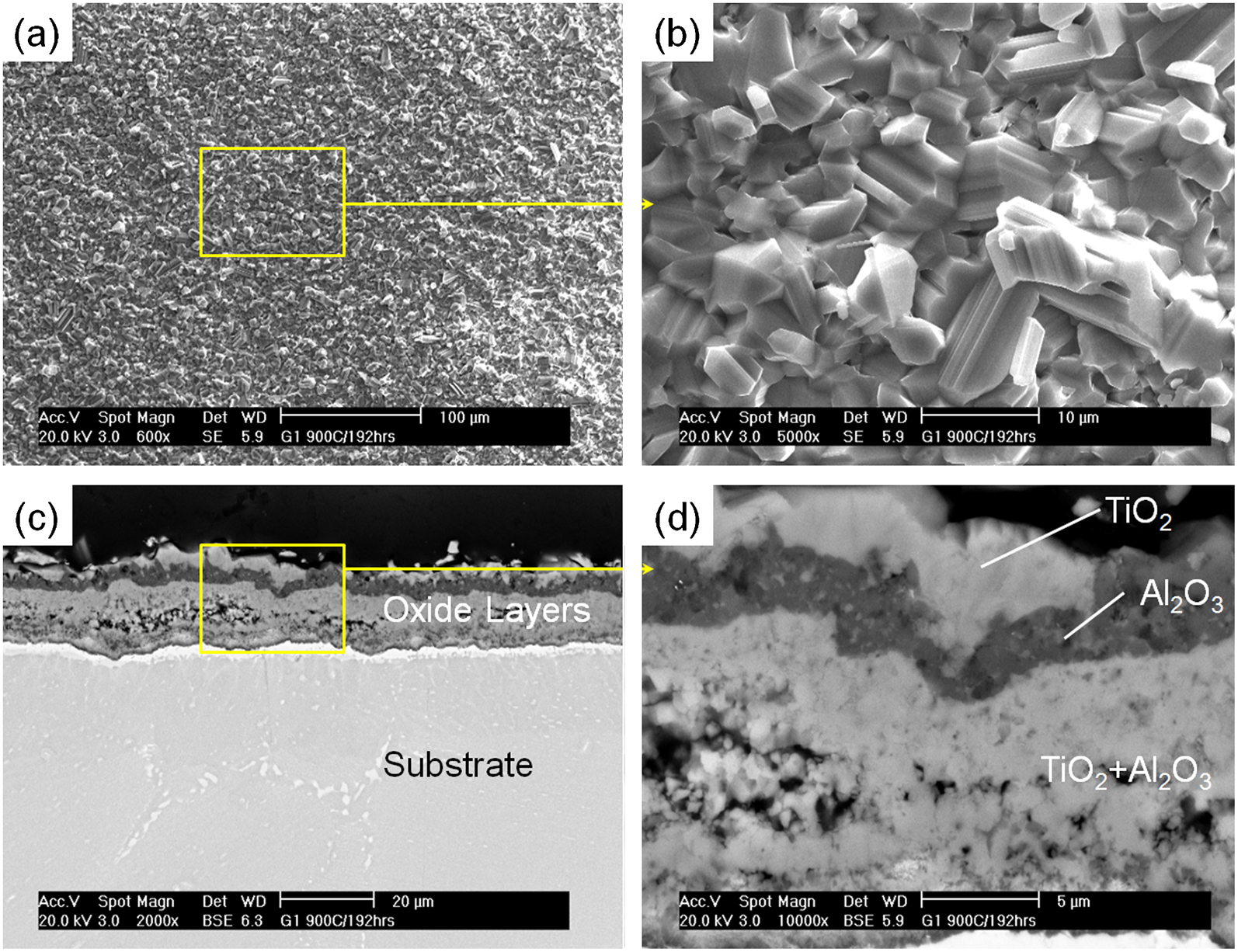
Low and high magnification SEM micrographs of a TiAl–4Nb–3Mn (at.-%) TiAl alloy that was isothermally aged at 900°C for 192 h in air, showing a surface oxides (×600), b TiO2 grains formed on the top of the surface oxides (×5000), c cross-section (×2000) and d close-up view on the oxide layers (×10 000)
The poor oxidation behaviour of γ-TiAl alloys in air, as compared to in pure oxygen, is commonly referred to as the 'nitrogen effect'. 26,27 The inability of binary γ-TiAl alloys to establish a continuous Al2O3 scale in air at 800–900°C is closely related to the formation of titanium nitrides (TiN or Ti2AlN) at the oxide/substrate interface during the early stages of oxidation. 26,27 It is known that the oxide scale is permeable to nitrogen from the atmosphere and the amount of nitrogen detected at the oxide/substrate interface increases with oxidation time. 27 Figure 4 shows cross-sectional microstructures of an experimental TiAl alloy (TiAl–xNb–yW–zSi, at.-%) after a cyclic oxidation test at 900°C in air with corresponding EDS results. In the micrographs, cross marks represent the points at which the element concentrations were measured by point EDS analysis. The EDS results demonstrate the formation of the titanium nitride at the oxide/substrate interface after 192 cycles and their growth with an increase of the exposure time. Approximately, 60–70 at.-%Al was needed for binary Ti–Al alloys to form a continuous Al2O3 scale in air whereas only about 47–49 at.-%Al was needed for binary Ti–Al alloys to form a continuous Al2O3 scale in pure oxygen. 28
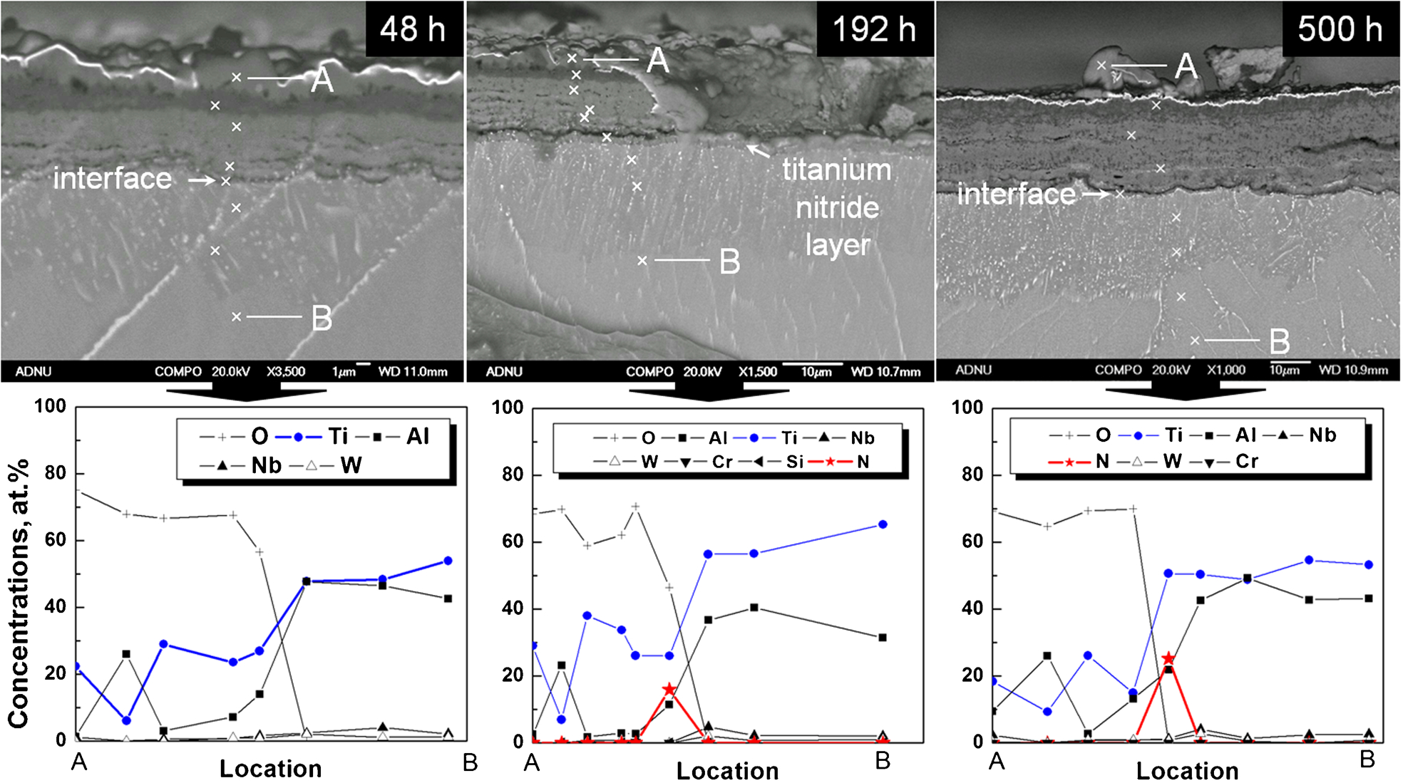
Cross-sectional SEM micrographs of TiAl–xNb–yW–zSi (at.-%) alloy after cyclic oxidation test at 900°C in air and corresponding results of point EDS analyses
Taniguchi 22,23 suggested a model for the progressive development of the oxide scale on TiAl at elevated temperature (Fig. 5). During the initial period, both Ti and Al are oxidised to form TiO2 and Al2O3 grains, respectively (Fig. 5a ). Immediately after this, the TiO2 grains overgrow the Al2O3 grains because of the difference in the growth rates, resulting in an outer TiO2 layer and an inner porous layer (b to d). The sequence of void formation can be explained in terms of the initial growth of the TiO2 grains almost normal to the specimen surface, followed by their lateral growth. 22 The outer TiO2 layer and porous TiO2+Al2O3 layer grow by outward-diffusion of titanium ions and inward-diffusion of oxygen ions. 22
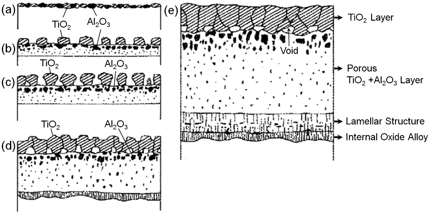
Model for the progressive development of the scale on TiAl at elevated temperatures 22
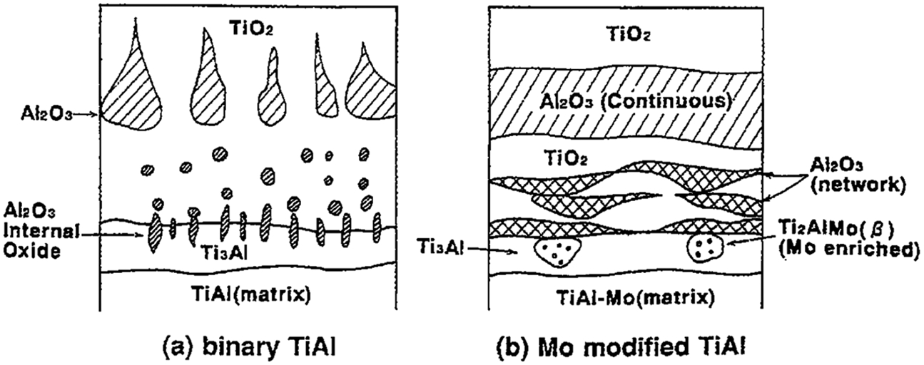
Y. Shida and H. Anada 29 also reported that binary TiAl alloys containing less than 65 at.-%Al had non-protective multi-layered oxide scales composed of the TiO2/Al2O3/TiO2+Al2O3/internal oxide zone (Al2O3 in the Ti3Al matrix) whereas alloys containing 75 at.-%Al (TiAl3) had a uniform protective scale composed of TiO2/Al2O3 without the internal oxide zone. The outer TiO2 and inner mixed layers continued to grow as the TiO2 was permeable for both Ti and oxygen ions. 29 The transport of Ti and oxygen ions by outward- and inward-diffusion, respectively, along the micro-intergranular channels eventually formed continuous TiO2 paths bridging the top TiO2 giving a linear growth rate leading to the Al2O3 layer breaking into islands (termed breakaway stage) in the sea of TiO2. 30 Fig. 6a shows the thickness of the top TiO2 and the inner TiO2 layers increased rapidly after breakaway stage. The oxide thickness reduces drastically as the at.-% of Al increases as shown in Fig. 6b . 29
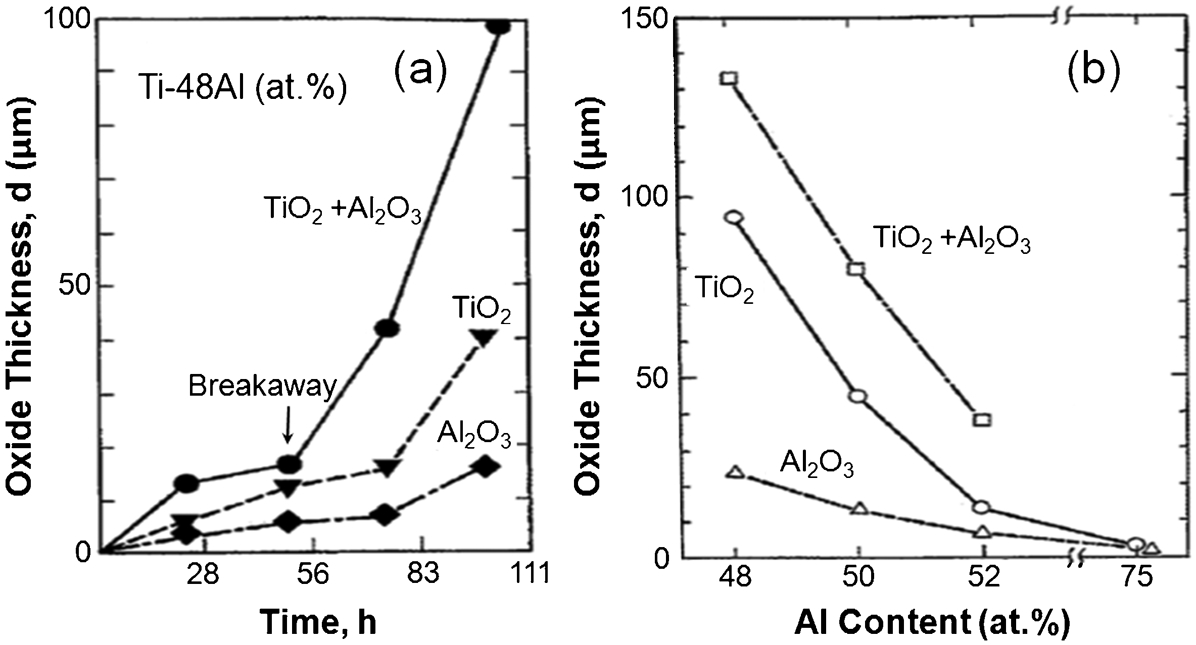
Variation of thickness of each oxide layer a with time and b with Al content, obtained for Ti–48Al (at.-%) oxidised at 900°C for 100 h 29
Oxidation kinetics of TiAl alloy
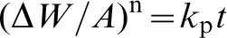
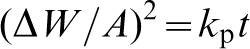
The parabolic rate constant (k
p) represents oxidation kinetics and can be obtained from the weight gain per unit area (ΔW/A) curve fitted to the following equation.
25,31
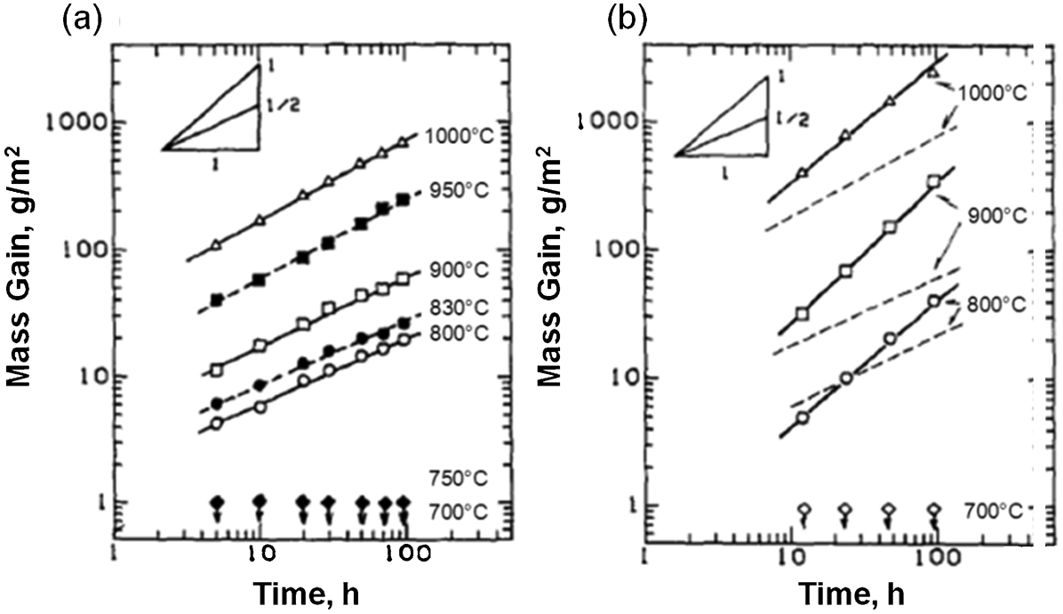
a Isothermal and b cyclic oxidation behaviours of Ti–47Al (at.-%) 32
The oxidation kinetics of the binary γ-TiAl alloy also changed with Al content in the alloys. Y. Shida and H. Anada 29 investigated the oxidation behaviour of binary TiAl alloys with varying Al content (31·7, 48·7, 50·3, 52·1, 65·1, and 75·2 at.-%). As the Al content increased, the mass gain decreased (Fig. 8a ). The oxidation kinetics also changed with time as seen in Fig. 8b . The break in the curve for both the 31·7 and 48·7 at.-% of Al represents a change in the oxidation kinetics, from parabolic to linear (this is commonly termed 'breakaway'). No such breakaway was observed for the high Al containing (75·2 at.-%) TiAl alloys.
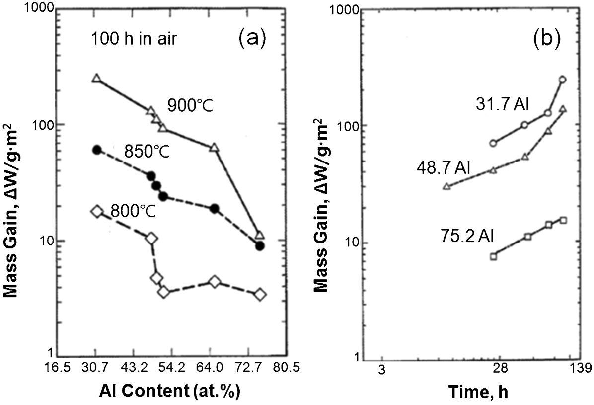
Variation of oxidation mass gain with a Al content in Ti–Al alloys, b time increase for several TiAl alloys at 900°C 29
The parabolic rate constant k
p is a function of temperature and the temperature dependence of k
p can be expressed by the following equation.
A linear regression of the plot of ln (k p) versus 1/T yields an activation energy Q for oxidation. 25 Figure 9 shows a plot of the activation energy Q as a function of Al content in binary TiAl alloys. TiAl alloy with more Al concentration requires more activation energy for oxidation indicating there are different oxidation mechanisms with Al content in TiAl alloys. With increased Al content, the activation energy for oxidation roughly follows an exponential relationship up to Ti–49Al (at.-%). Figure 10 is a plot of oxidation kinetics for TiO2 and Al2O3 with those of TiAl alloys. The k p values fall between that of Al2O3 and TiO2 formation since the products of oxidation of TiAl alloys are two phase mixtures of Al2O3 and TiO2. 30
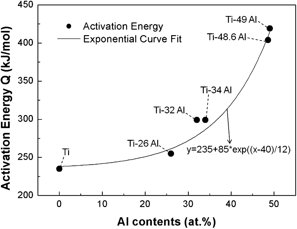
Plot of Q as a function of Al content for Ti and binary TiAl alloys 25
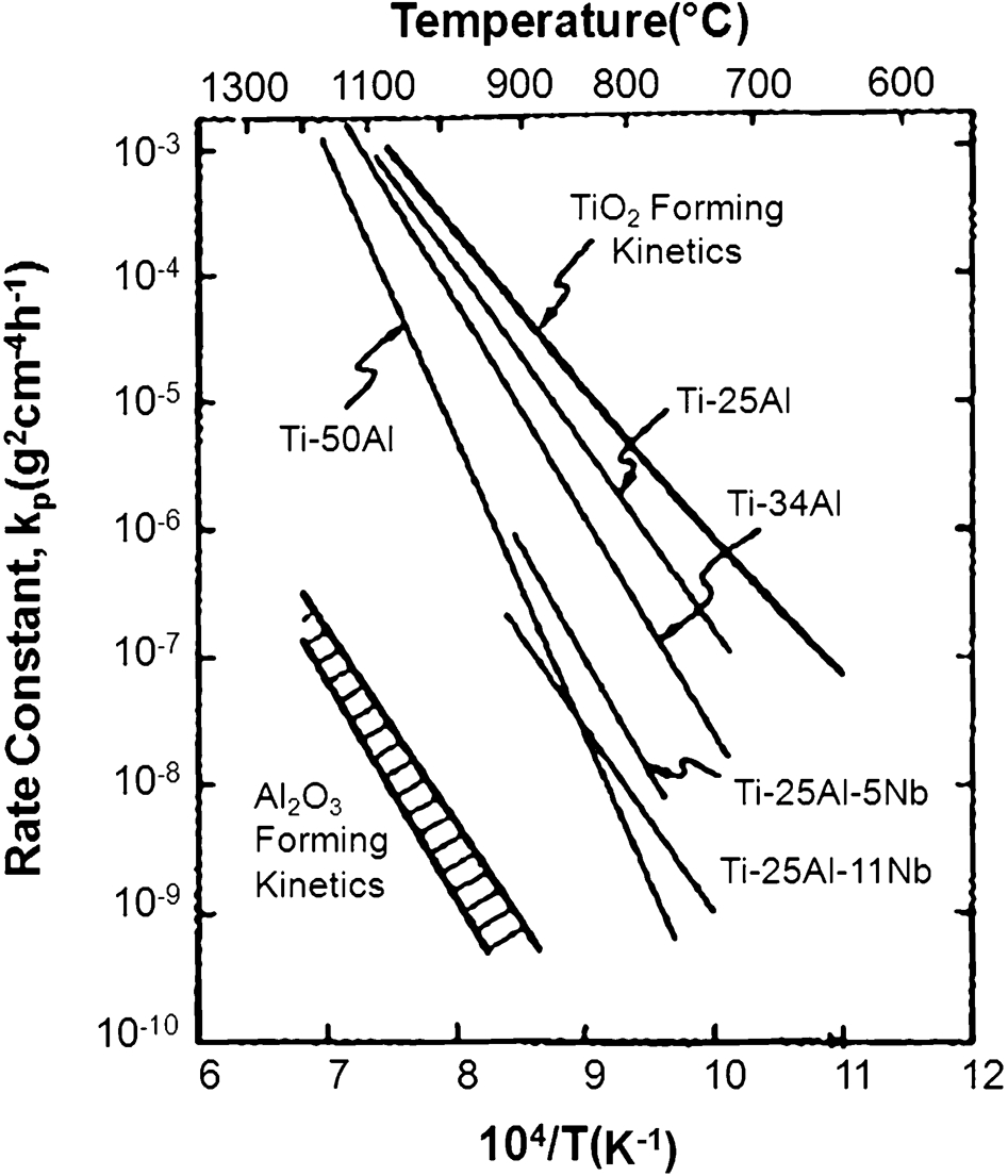
Oxide forming kinetics for TiAl and other TiAl alloys (at.-%) compared with TiO2 and Al2O3 forming kinetics 1
Effect of element addition on the oxidation of TiAl alloy
Although the oxidation resistance of binary TiAl alloys is poor above 750°C, their temperature capability can be increased up to 950°C by alloying ternary or quaternary elements. Y. Shida and H. Anada 33 classified the effect of various elements on the oxidation behaviour of a binary TiAl (Ti–48Al, at.-%) into three groups (Table 1) based on the oxidation tests in air at temperatures between 800 and 1000°C. They also reported that at temperatures above 900°C, the relative effectiveness of the alloying element followed the order: W>Mo>Nb>Si. 34 The effect of different elements on TiAl alloys in terms of oxidation resistance and oxidation behaviour is summarised in Table 1 and elaborated on in the following sections.
Effect of various elements on oxidation resistance 33
Effect of W addition
Among the beneficial elements in Table 1, W is particularly beneficial to oxidation resistance. 33 In the case of Ti–48Al–xW (at.-%, x = 0, 0·4, 0·8, 1·3), the isothermal oxidation resistance of Ti–48Al (at.-%) alloy was significantly improved by the W addition at temperatures between 850 and 1000°C.
Adding W to binary TiAl reduced the solid solubility of oxygen within the bulk alloy, leading to a suppression of the Al2O3 phase within the internal oxide layer. 35 However, increasing W beyond 0·8 at.-% increases mass gain. 35 Figure. 11 shows the effect of 2 at.-%W addition to Ti–48Al (at.-%) alloy on the weight gain curves in isothermal and cyclic oxidation tests at temperatures between 900 and 1050°C. The oxidation resistance of Ti–48Al–2W (at.-%) was better than that of binary Ti–(47, 51)Al (at.-%), and was comparable to or better than that of Ti–48Al–2Cr–2Nb (at.-%), under isothermal and cyclic oxidation tests. 36 The better scale adherence of TiAl–2W (at.-%) over Ti–(47, 51) Al (at.-%) was believed to have originated mainly from reduction in growth stresses, because the TiO2 grains of Ti–48Al–2W (at.-%) were smaller than those of Ti–(47, 51)Al (at.-%). 36
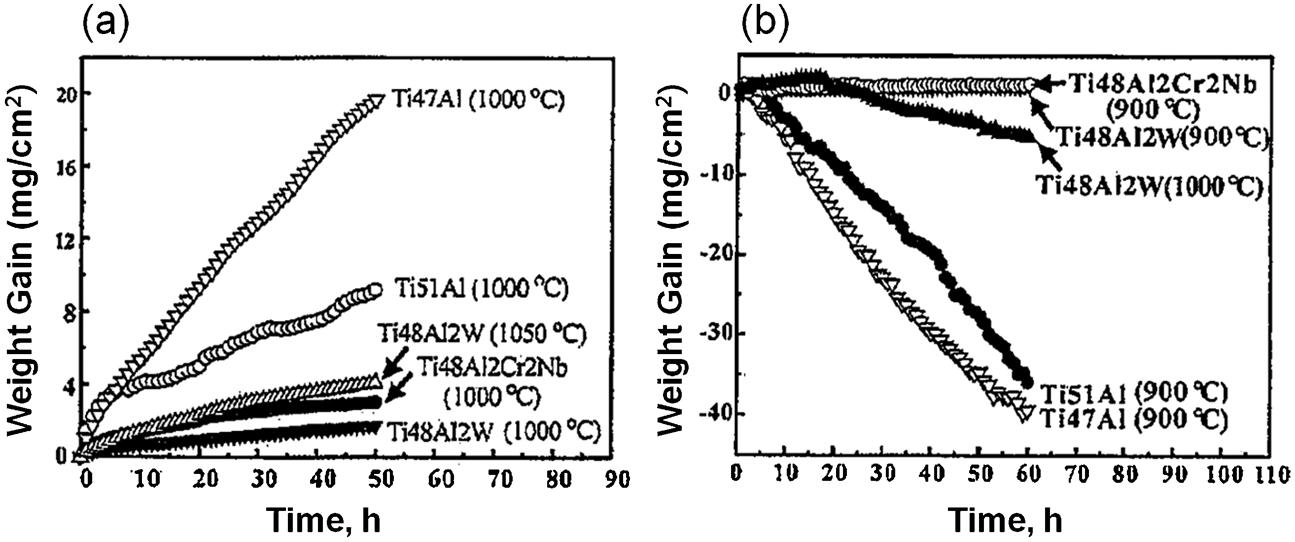
Weight gain curves of Ti–48Al–2W (at.-%) with Ti–47Al, Ti–51Al, Ti–48Al–2Cr–2Nb (at.-%) alloys in a isothermal oxidation test at 1000 and 1050°C in air, b cyclic oxidation test at 900 and 1000°C in air 36
Effect of Mo addition
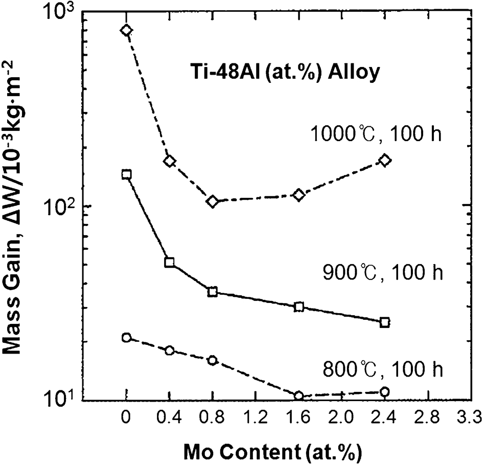
Figure 12 shows the effect of Mo addition on the mass gain of Ti–48Al (at.-%) during isothermal and cyclic oxidation in air at temperatures of 800, 900, and 1000°C. Mass gains decreased with Mo content at 800 and 900°C. At temperatures of 900 and 1000°C, Mo additions up to 0·8 at.-% dramatically reduced the mass gain. However, at 1000°C, alloying Mo beyond 2 at.-% increased mass gain. As shown in Fig. 13, surface oxides that formed on the Mo-modified TiAl alloy have a layered structure of TiO2/Al2O3/TiO2+Al2O3/Ti3Al (Mo-enriched)/TiAl (matrix). The protective Al2O3 is more continuous in the Mo-modified alloy compared to the binary TiAl alloy due to a decrease of the oxygen solid solubility, which leads to external Al2O3 formation. 37
Effect of Mo content in Ti–48Al (at.-%) on mass gain during isothermal oxidation in air at various temperatures for 100 h 37
Schematic illustration for the scale structure of the Mo-modified Ti–48Al (at.-%) comparing with that of the binary TiAl 37
Effect of Cr addition
Based on previous experimental work, 38–41 the addition of small amounts of Cr (<4 at.-%) has a detrimental effect on the cyclic oxidation resistance of TiAl, while the addition of high concentrations (>8 at.-%) has a beneficial effect. For example, the oxidation resistance of Ti–48Al–xCr (at.-%, x = 0·5, 1·0, 2·0) alloys at 900°C was not improved compared to Ti–48Al (at.-%) alloy, 39 and the addition of 1·5 at.-%Cr was detrimental to the oxidation behaviour of Ti–48Al–1·5Cr (at.-%) alloy at the temperatures of 704, 815 and 982°C. 40 Also, the oxidation resistance of the binary TiAl alloys at 900°C was not improved by adding 2–4 at.-%Cr, as shown in Fig. 14. Ti–48Al–(2–4)Cr (at.-%) failed to develop a continuous alumina scale, and the cause of the oxide spallation in Fig. 14 was the embrittlement in the regions beneath the surface oxides to depths of several microns. 41 However, the oxidation rate decreased with increasing Cr content. The additions of more than 8 at.-%Cr to Ti–(44–55)Al (at.-%) alloys has a beneficial effect, as shown in Fig. 14, due to the development of dense protective alumina scales during cyclic oxidation. 41 The 10 at.-%Cr additions (Ti–50Al–10Cr) remarkably improved both the isothermal and cyclic oxidation resistance of TiAl alloys over the temperature ranges of 800–1100°C due to enhanced formation of Al2O3-rich scales. 38 The excellent adhesion of Al2O3 scales resulted from the reduced difference in the thermal expansion coefficients between the Al2O3 scales and the Ti–50Al–10Cr (at.-%) substrate leading to the low thermal stress of Al2O3 scales. 38
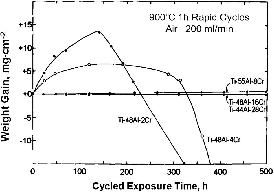
Weight change versus cycled time for Ti–Al–Cr alloys containing 2–28 at.-%Cr during rapid thermal cycle at 900°C in air 41
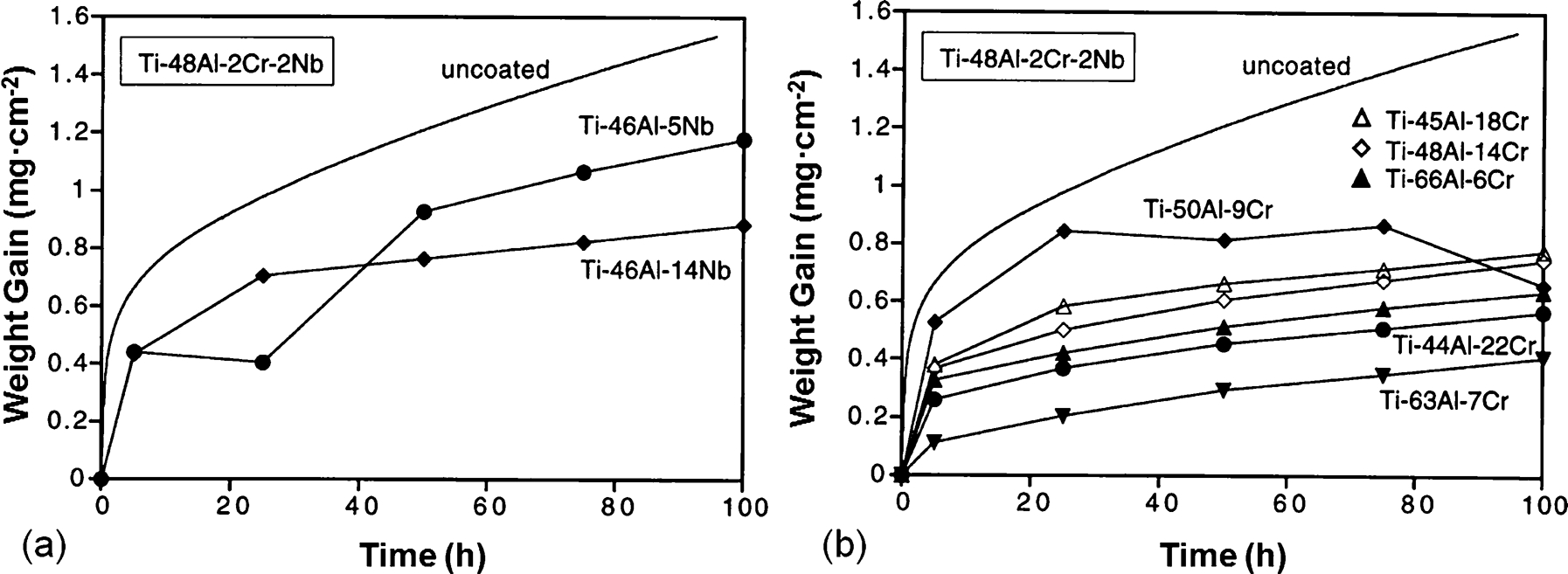
Effect of Nb and Si addition
Niobium is believed to be one of the most effective elements to improve oxidation resistance of TiAl alloys. At temperatures of 850–900°C, the oxidation resistance of Ti–48Al–xNb (at.-%, x = 0, 4, 8, 12) and Ti–48Al–2Cr–xNb (at.-%, x = 2, 4, 12) alloys increased with increasing Nb concentrations in the alloy. 41 Ti–48Al–2Mn–2Nb (at.-%) improved oxidation resistance against isothermal and cyclic oxidation in air at 800 and 900°C. 42
Figure 15 shows a schematic diagram for oxidation mechanisms in Nb/Si-modified TiAl alloys. Nb is known to accelerate the formation of Al2O3. 43,44 H. Jiang et al. 45 reported that the Nb addition could improve the oxidation resistance of Ti–Al alloys by impeding mass transfer in TiO2. W. Lu et al. 46 reported that the doping of Nb in TiO2 grains reduced oxygen vacancy and interstitial Ti cations, which promotes the formation of the Al2O3 enrichment layer (black region in Fig. 15c ), on the top of the mixture layer (white region immediately to the right of the black region in Fig. 15c ). It seems that the oxidation mechanism of the Nb-modified TiAl alloys is not yet clear and needs further investigation.
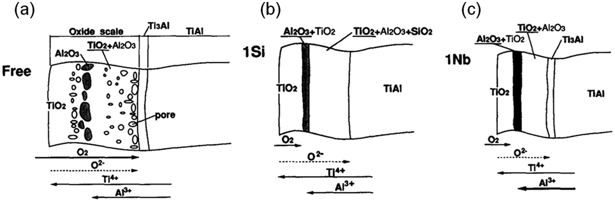
Schematic diagram of the oxide scale and diffusion barrier layer of a binary TiAl, b Si-modified, and c Nb-modified TiAl alloys 43
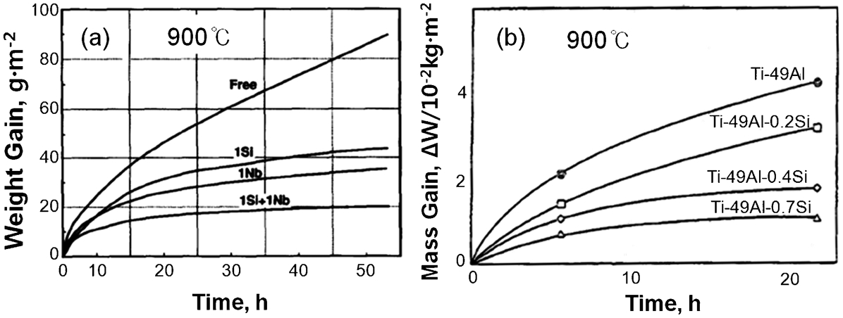
The addition of 0·4 at.-% of Nb or 1·4 at.-%Si to Ti improved the oxidation resistance of Ti–47Al (at.-%) alloy at 900°C as shown in Fig. 16a , and their synergistic effect on the improvement is better than their effects individually. In Ti–49Al–xSi (at.-%, x = 0·2,0·4,0·7,1·3) alloys, the addition of Si decreased the mass gain at 900°C up to 0·7 at.-%Si as shown in Fig. 16b . However, there was no further increase in oxidation resistance when the Si content is greater than 0·7 at.-%. 39 Together with the Al2O3 layer in the oxide scale, Si formed crystalline and/or amorphous SiO2 in the oxide scale and this SiO2 acted as a barrier against oxidation and suppressed oxide spalling. 43 The formation of continuous SiO2 film at the alloy/oxide interface assisted the protective ability of the Al2O3 layer against oxidation by decreasing the diffusion rate of alloying elements and oxygen ions. 39
Effect of Y addition
On the improvement in the oxidation resistance of Y-added TiAl alloys, both beneficial and detrimental effects have been reported depending on the alloy compositions and test conditions. In the case of isothermal oxidation at 900°C, previous reports 39,47,48 indicated a transition from beneficial effect to detrimental effect with increasing concentration of Y. For example, the addition of a large amount of Y (2 at.-%) to Ti–50Al (at.-%) increased the ingression of oxygen, leading to mass gain, while a small amount (0·1, 0·2 and 1·0 at.-%) was effective in reducing spalling and breaking of the oxide scale. 47 Similarly, for Ti–50Al–xY (at.-%, x = 0, 0·1, 0·3, 0·6, 1·0), a small amount of Y addition (0·1 and 0·3 at.-%) improved oxidation resistance while higher Y contents (0·6 and 1·0 at.-%) had a detrimental effect on the oxidation resistance. 48 The Y addition of more than 0·4 at.-% in Ti–50Al–xY (at.-%, x = 0·5, 1·0, 2·0) was not helpful in improving the oxidation resistance in air, although it improved the adherence of the surface oxide. 39 Under cyclic oxidation at 800°C, regardless of the amount of Y, the Y-modified alloys of Ti–50Al–xY (at.-%, x = 0, 0·1, 0·3, 0·6, 1·0) were more oxidation-resistant than binary TiAl alloys, as shown in Fig. 17. Compared to the binary TiAl alloys, the structures of oxide scales formed on the Y-added (0·6, 1·0 at.-%) alloy was very thin, and it had a continuous Al2O3 layer and a unique intermediate Y-rich layer (Al5Y3O12) right above the substrate, as shown in Fig. 18. The improvement of the oxidation resistance in the alloys with Y was mainly due to the outer Al2O3 layer, which inhibited the ingression of oxygen, and also due to the inner Y-rich layers, which were inferred to reduce the thermal stress. 48
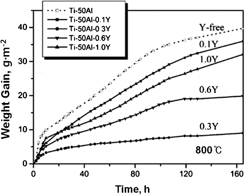
Effect of Y on the oxidation kinetics of Ti–50Al (at.-%) based alloys in synthetic air with a flow of 200–250 ml min−1 at 800°C under cyclic oxidation. Samples were heat treated at 1400°C 1 h−1 AC−1 before oxidation tests 48
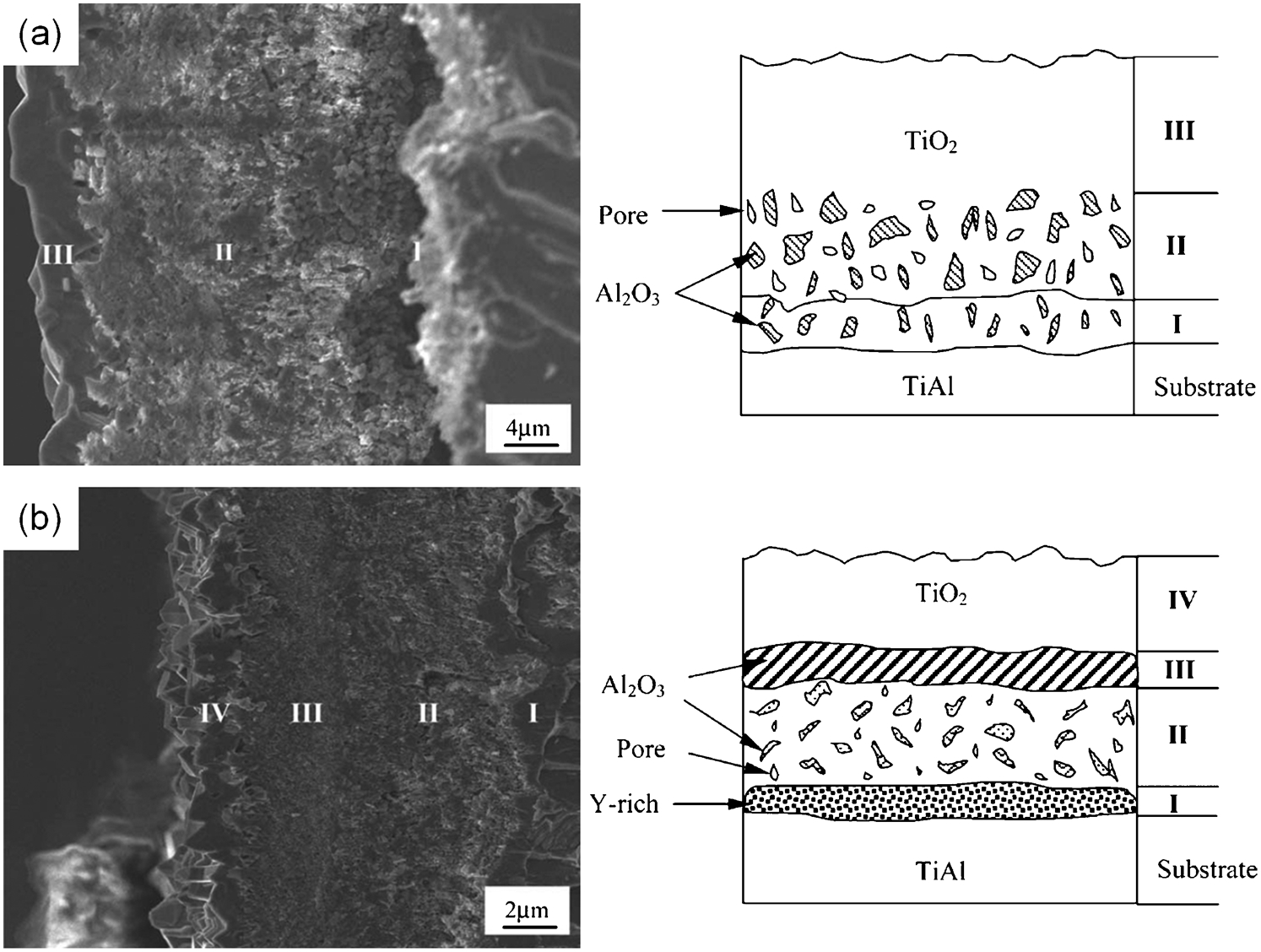
SEM micrograph and schematic of the cross-sectional morphologies of the oxide scales formed at 800°C after 165 h of cyclic oxidation in a Y-free alloy and b 0·6 at.-%Y-added TiAl alloy 48
Effect of Fe, Ta and REM addition
In the isothermal oxidation tests at 800, 900, and 1000°C in air, the overall oxidation kinetics and the scale morphology of Ti–48·73Al–0·4Fe (at.-%) and Ti–49Al–Fe (at.-%) alloys were not affected by Fe addition. 49 Under rapid thermal cycling conditions in air, direct addition of 2 and 4 at.-%Ta to the binary Ti–48 at.-%Al alloy increased the tendency of the alloy to form spalling oxide scales at 850°C. When Ti–48Al–(2–4)Ta (at.-%) alloys were tested at 900°C, marked sub-surface embrittlement was observed. 41 However, when Ta was added with the addition of Cr, the oxidation resistance increased with increasing Ta concentrations in the Ti–48Al–2Cr–xTa (at.-%, x = 2, 4, 6) alloys. 41 The addition of 0·2 at.-% of rare earth materials (REM) such as Ce, Nd, Sm, Tb and Dy to Ti–50Al (at.-%) alloy suppressed breaking and spalling of the oxide scale, thus improving the oxidation resistance during cyclic oxidation in air at 900°C, as shown in Fig. 19. 47
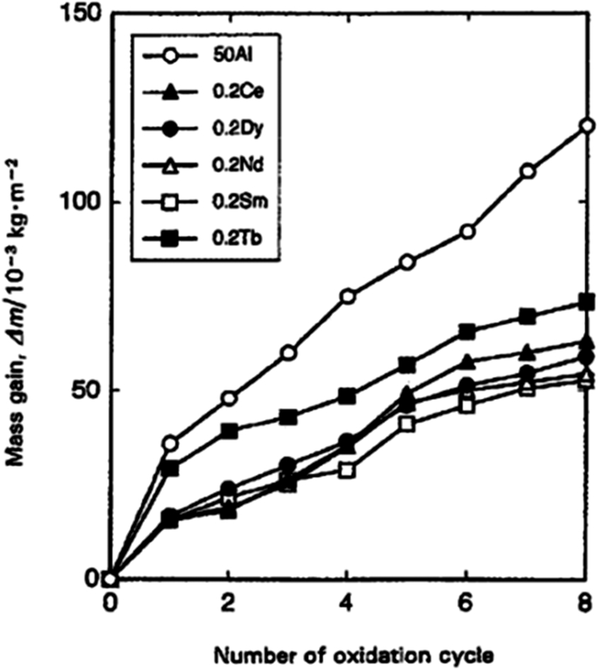
Mass gains including spalled oxide during cyclic oxidation of TiAl alloys doped with various rare earth materials (REM). The samples were oxidised at 900°C for 5 h on each cycle 47
Oxidation behaviour of beta-gamma TiAl alloy
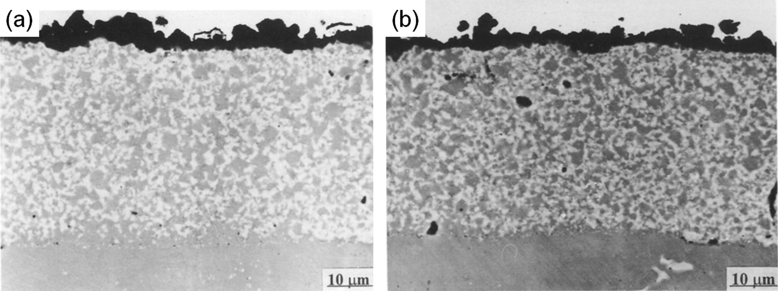
Beta gamma alloys such as TiAl–4Nb–3Mn (at.-%) 50 and TiAl–2Nb–2Mo (at.-%) 51 were isothermally oxidised at 800 and 900°C in air up to 500 h. Figure 20 shows the FL microstructures of the as-fabricated TiAl–4Nb–3Mn (at.-%) and TiAl–2Nb–2Mo (at.-%) alloys and the samples after the oxidation tests. Figure 21 shows typical oxides formed on the TiAl–4Nb–3Mn (at.-%) and TiAl–2Nb–2Mo (at.-%) alloys after oxidation for 192 h at 900°C. The oxide layer consists of an outer TiO2 layer, an intermediate Al2O3 layer, and an inner TiO2+Al2O3 mixed oxide layer. Such oxides structures are typical for oxidised TiAl alloys. The oxidation mechanisms of the alloys were identical between 800 and 900°C. There was a TiN phase formation at the oxide/substrate interface owing to the nitrogen effect 26,27 in both TiAl–4Nb–3Mn (at.-%) and TiAl–2Nb–2Mo (at.-%) alloys.
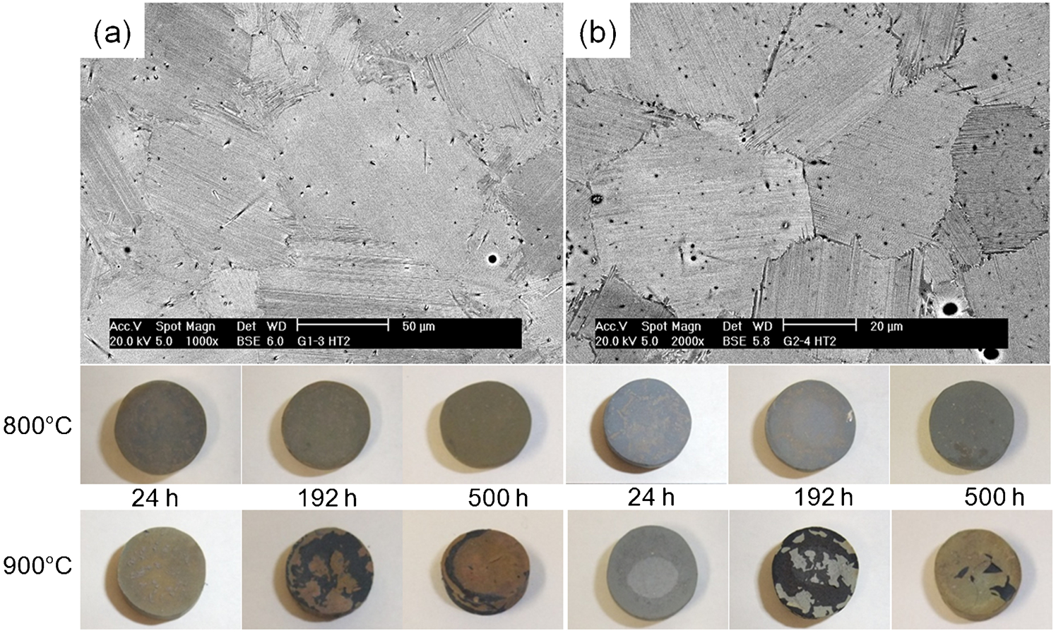
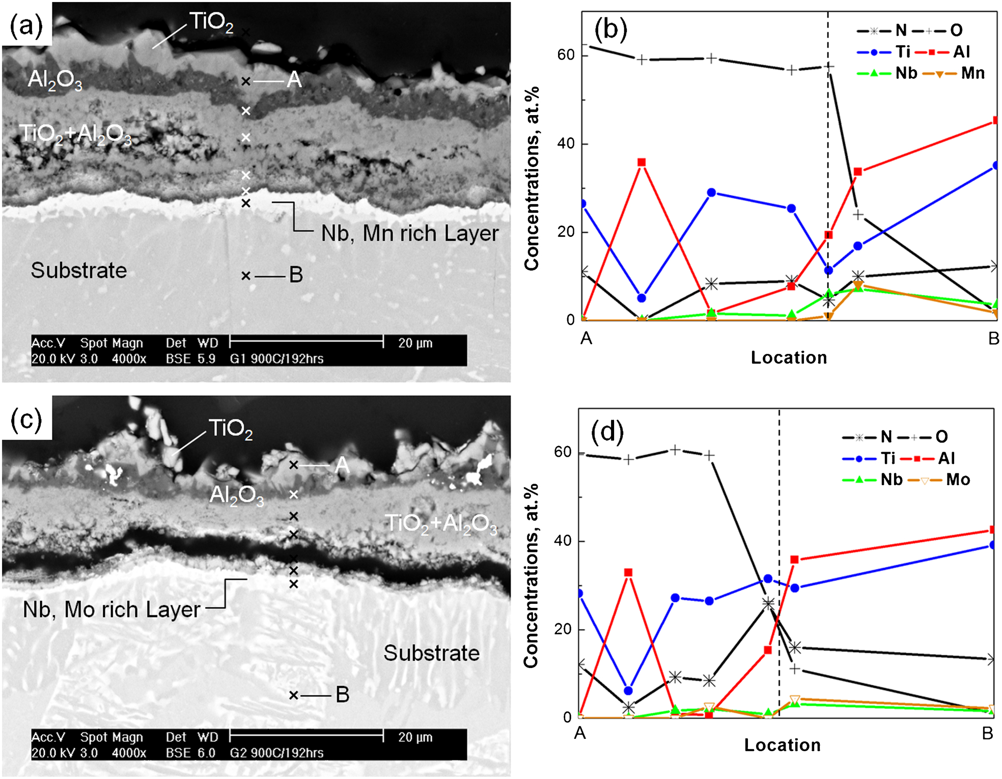
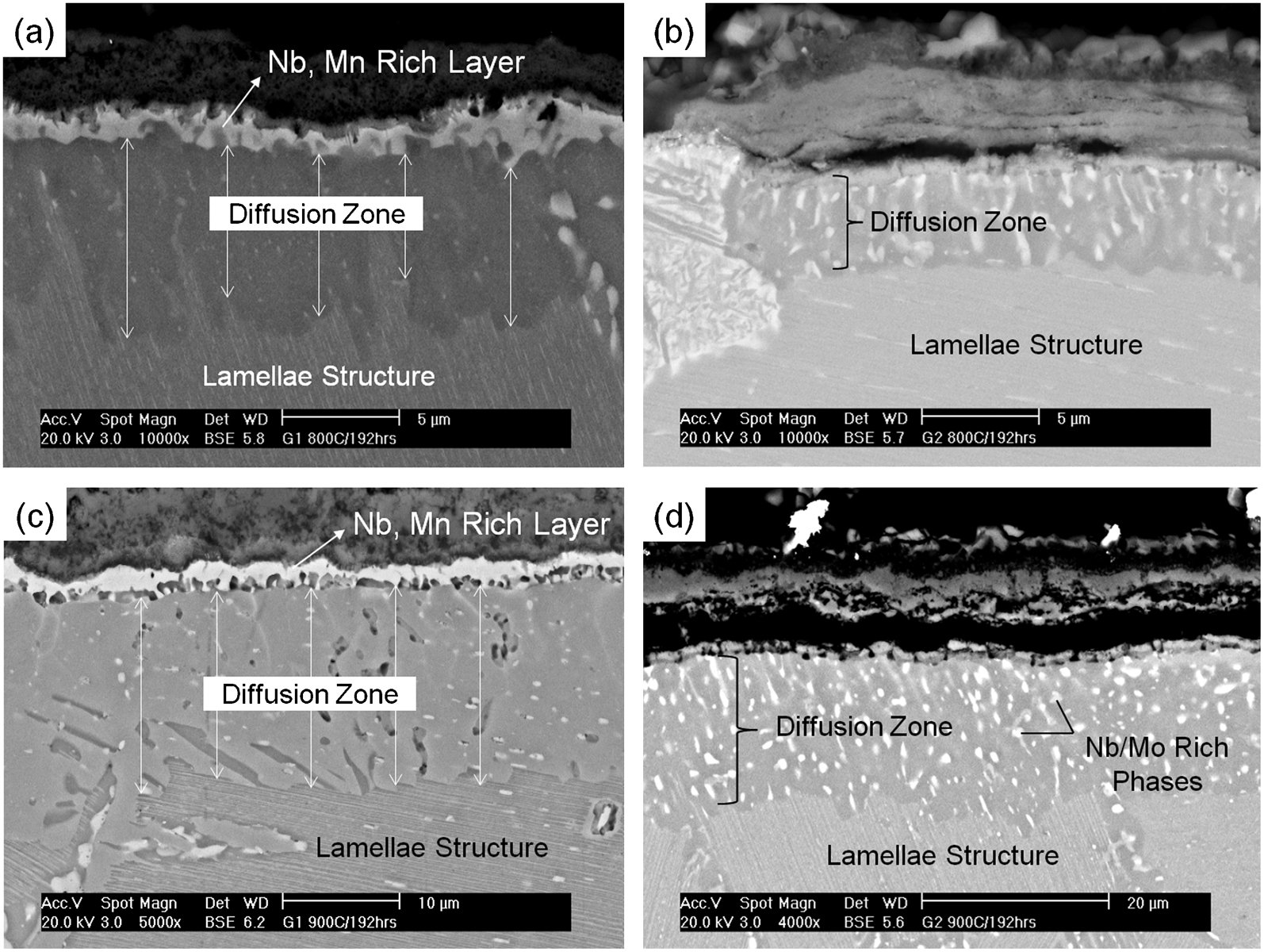
Figure 22 shows the cross-sections of the TiAl–4Nb–3Mn (at.-%) and TiAl–4Nb–3Mn (at.-%) alloys after oxidation for 192 h at 800 and 900°C. The formation of diffusion zones below the interface between the oxides and the substrates can be seen. The substrate is originally a FL structure with γ and α2 lamellae phases as shown in Fig. 20a and b and the α2 phase is known to be rich in beta stabiliser elements such as Nb and Mn. M. Yoshihara and Y-W. Kim 52 reported that the enrichment of Nb in the beta phase could suppress the oxide growth due to the synergistic effect of two mechanisms; (1) high Al diffusion in the beta phase results in the enhanced Al2O3 formation, and (2) the doping effect of Nb suppresses TiO2 growth. However in Fig. 22, the lamellar structure no longer exists in the diffusion zone. Similar phenomenon was found during ageing of a powder metallurgy (PM) Ti–48Al–2W (at.-%) alloy at 950°C where the α2 lamellar became discontinuous with ageing time. 53 In both TiAl–4Nb–3Mn (at.-%) and TiAl–4Nb–3Mn (at.-%) alloys, the discontinuous α2 lamellae were also observed in the area below the diffusion zone, suggesting that the diffusion zone (lamellar depleted zone) has formed by the breakdown of α2 lamellae in the region. The release of the beta phase forming elements from α2 lamellae and subsequent outward-diffusion of those elements led to the formation of white layers in the vicinity of the interface (TiAl–4Nb–3Mn (at.-%), Fig. 22c ) and the formation of the dispersed Nb and Mo beta phases in the diffusion zone (TiAl–4Nb–3Mn (at.-%), Fig. 22d ). The weight gain curves of the two beta gamma alloys obey the parabolic law during oxidation at 800 and 900°C up to 500 h (Fig. 23), confirming that it is a diffusion-controlled process. Additionally, Mn is a favourable alloying element compared to Cr for oxidation resistance at 800°C because the weight gains of TiAl–4Nb–3Mn (at.-%) and Ti–48Al–2Mn–2Nb (at.-%) alloys are significantly lower than Ti–48Al–2Cr–2Nb (at.-%) alloy at 800°C.
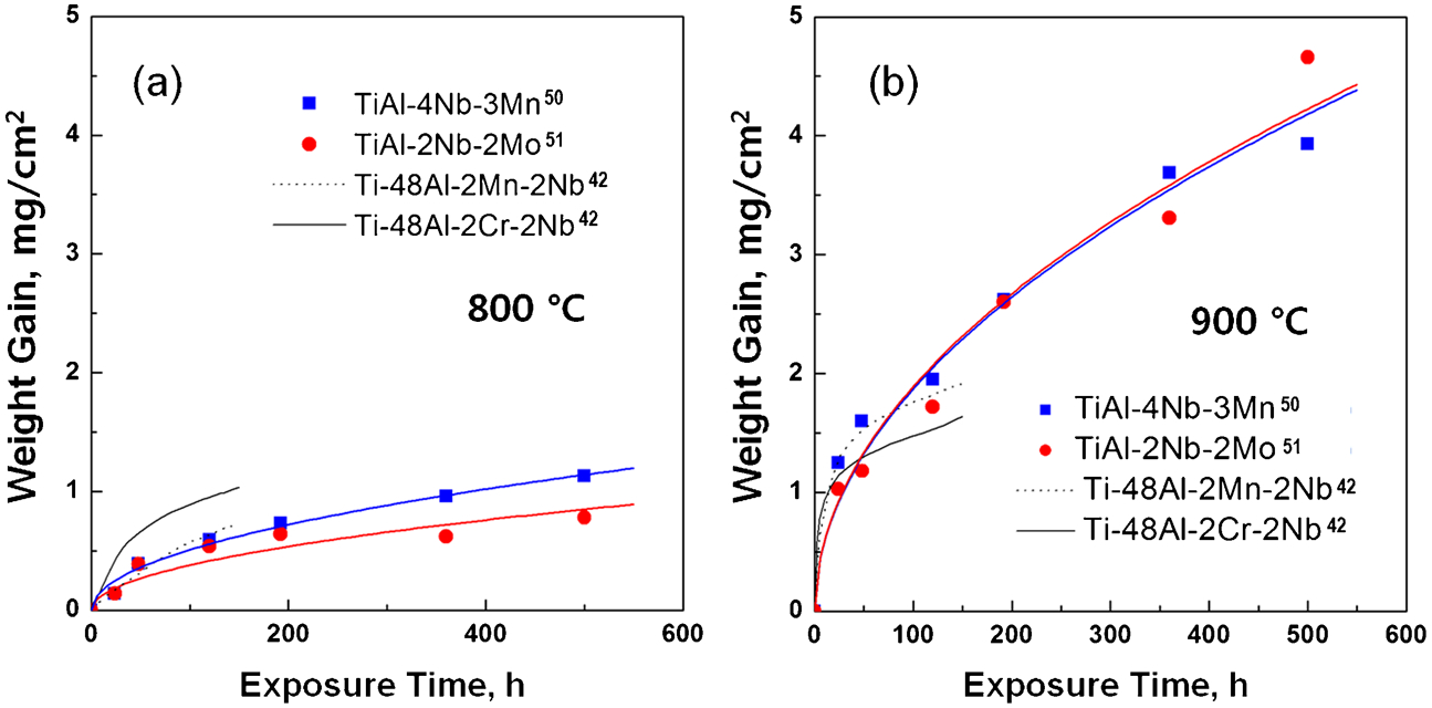
Weight gain curves for the TiAl–4Nb–3Mn (at.-%) and TiAl–2Nb–2Mo (at.-%) beta gamma alloys and other quaternary TiAl alloys at a 800 and b 900°C. Note that each data point represents one independent specimen
Figure 24 shows the oxide forming kinetics for TiAl–4Nb–3Mn (at.-%) and TiAl–2Nb–2Mo (at.-%) alloys compared with those of binary TiAl alloys, 1,54 Ti–48Al–2Cr–2Nb–(0, 0·5, 1)W (at.-%) alloys, 55 Ti alloy, TiO2, and Al2O3. 56 The k p values of TiAl–4Nb–3Mn (at.-%) and TiAl–2Nb–2Mo (at.-%) alloys are similar and both fall between the Al2O3 and TiO2-forming k p values. The slope of the straight line for the TiAl–4Nb–3Mn (at.-%) and TiAl–2Nb–2Mo (at.-%) alloys between 800 and 900°C is steeper than that of Ti–48Al–2Nb–2Cr–xW (at.-%) alloys, which indicates that the oxidation rate of beta gamma alloys are more sensitive to temperature than those of γ-TiAl alloys containing beta stabilisers.
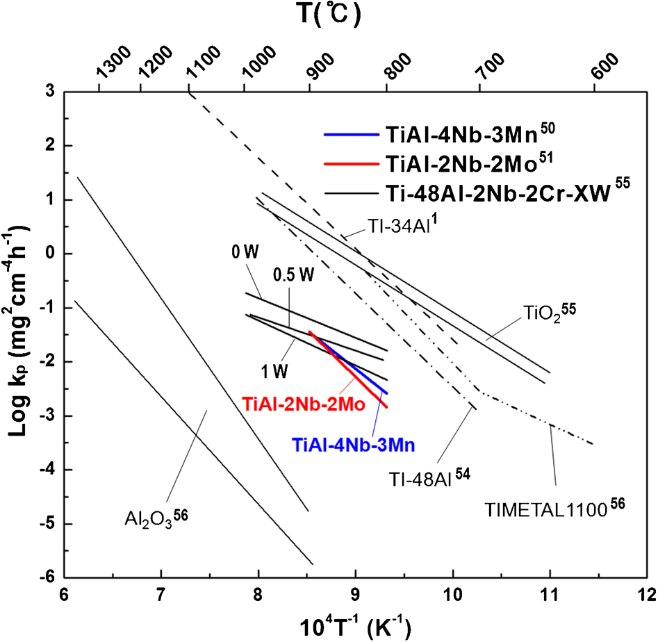
Oxide forming kinetics of TiAl–4Nb–3Mn (at.-%) and TiAl–2Nb–2Mo (at.-%) beta gamma alloys with other publication data
Oxidation behaviour of γ-TiAl alloy with intermetallic coating
There are two main approaches to enhance oxidation resistance of TiAl alloys above 800°C: alloy design, and surface coating. Past research indicates that the improvement to oxidation resistance of TiAl alloys relies on surface coating rather than alloy design. 44,57 Several coatings have been developed and investigated in the past, which include aluminising, MCrAlY (M = Co, Ni) 19 overlay, and Ti–Al–X coatings. All three coating technologies can improve the oxidation resistance of TiAl alloys at 800–900°C by forming a protective Al2O3 scale on the coating surfaces. 19
Oxidation behaviour of aluminised γ-TiAl alloy
Aluminising a γ-TiAl alloy results in the formation of an Al rich TiAl3 layer. The resultant TiAl3 layer can increase the high-temperature oxidation resistance of γ-TiAl. 58 Of the many reported aluminising processes such as aluminium cladding, aluminium deposition by ion-beam-assisted-deposition, and pack cementation (PC), pack-cementation processes show promise for oxidation resistance because of their simple procedure and effectiveness. 59 The pack material consists of pure or alloyed powders, a halide salt as an activator, and an inert filler (normally Al2O3). The coating is formed via decomposition of halide vapours (formed by the reaction between the activator and the metal powder) on the TiAl surface and subsequent solid state diffusion. 19 Coatings based on the TiAl3 phase have been successfully produced on TiAl alloys by pack cementation. 60
Oxidation of TiAl3
In the Ti–Al system, there are four intermetallic compounds: Ti3Al, TiAl, TiAl2 and TiAl3. 24 Among them, TiAl3 is the most oxidation-resistant phase in the Ti–Al system. 62 It is known that the TiAl3 phase with greater Al content forms a protective Al2O3 layer during the oxidation process, 58 and this protective nature becomes more pronounced as temperature increases. 24 TiAl and Ti3Al have been reported to exhibit poor oxidation resistance at temperatures above 800°C due to the formation of a detrimental TiO2 or a mixture of TiO2 and Al2O3 instead of a protective Al2O3 film. 24
Figure 25 shows the superior oxidation resistance of TiAl3 over that of TiAl. The representative surface oxides formed on TiAl and TiAl3 are shown in Fig. 26. The oxides on TiAl3 have a finer microstructure and smoother surface. On the other hand, the external surface of TiAl was covered with a mat of fine crystals of TiO2. The growth of randomly oriented, rod-like grains of TiO2 leads to the formation of numerous voids and pores at the grain boundaries which trigger crack initiation and spallation of oxide films from the substrate. 24
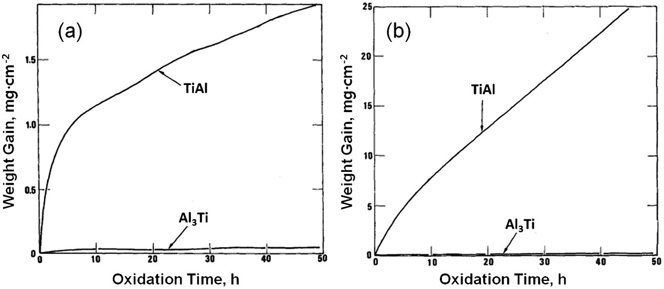
Variation of weight gain per unit area with oxidation time of Al3Ti and TiAl oxidised in oxygen a at 900 and b 1000°C 24
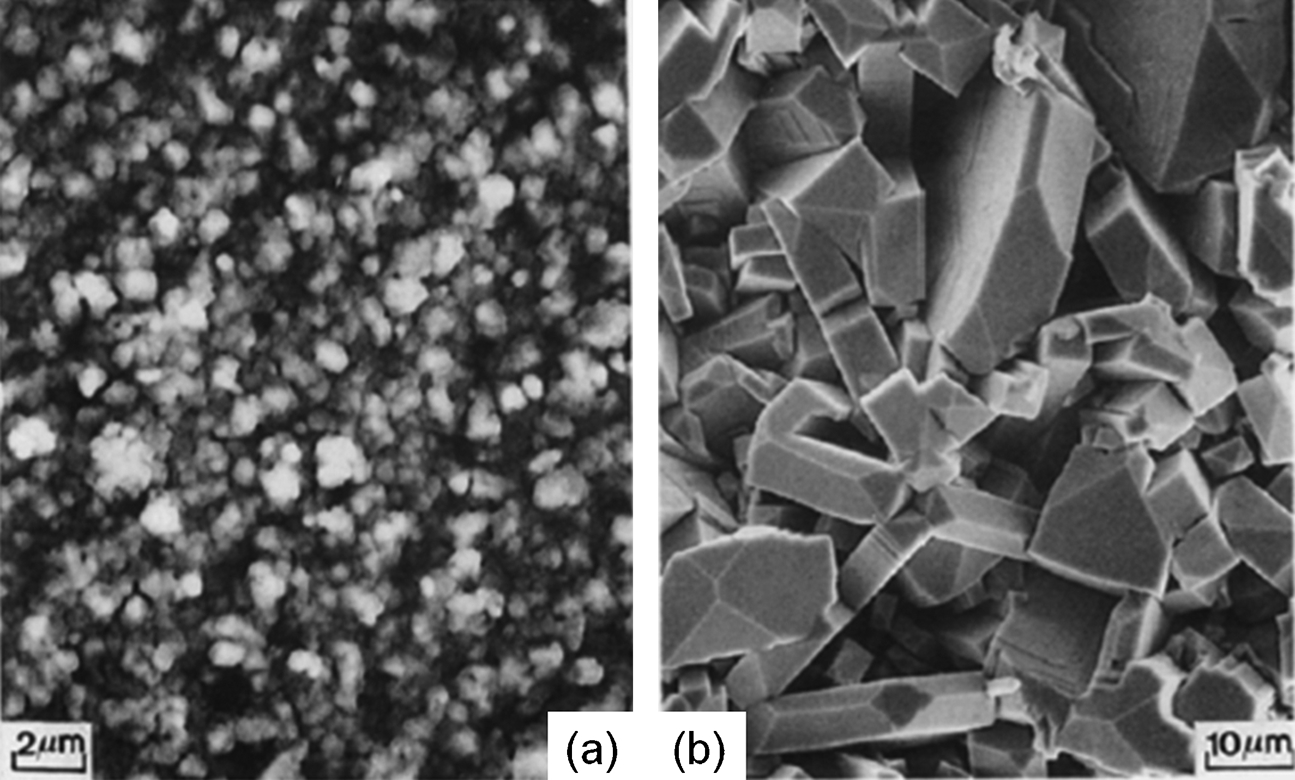
SEM micrographs of the surface oxide scales formed on Al3Ti and TiAl, a α-Al2O3 scale formed on Al3Ti exposed to oxygen at 1000°C for 48 h b TiO2 scale formed on TiAl exposed to oxygen at 1000°C for 48 h 24
Oxidation mechanism of aluminised γ-TiAl alloy
Pack cementation (PC) of γ-TiAl is a promising surface treatment for oxidation resistance. 61 A schematic illustration in Fig. 27a represents the oxidation process for an aluminised γ-TiAl (Ti–44·7Al–1·6Mn, at.-%) in the early stage of oxidation. Diffusion of Al is much faster than that of Ti in the TiAl3 coating layer. 61 As a result, the outward-diffusion of Al from the TiAl3 coating layer formed the Al2O3+(TiO2) and TiAl2 as the first and second layer, respectively (Fig. 27b ). The third and fourth sub-layers from the surface are formed by inward-diffusion of Al from the TiAl3 coating layer and the outward-diffusion of Ti from Ti3Al. Similarly, a four-layer surface structure was also found when tested under oxidation at 1000°C for 200 h. 61
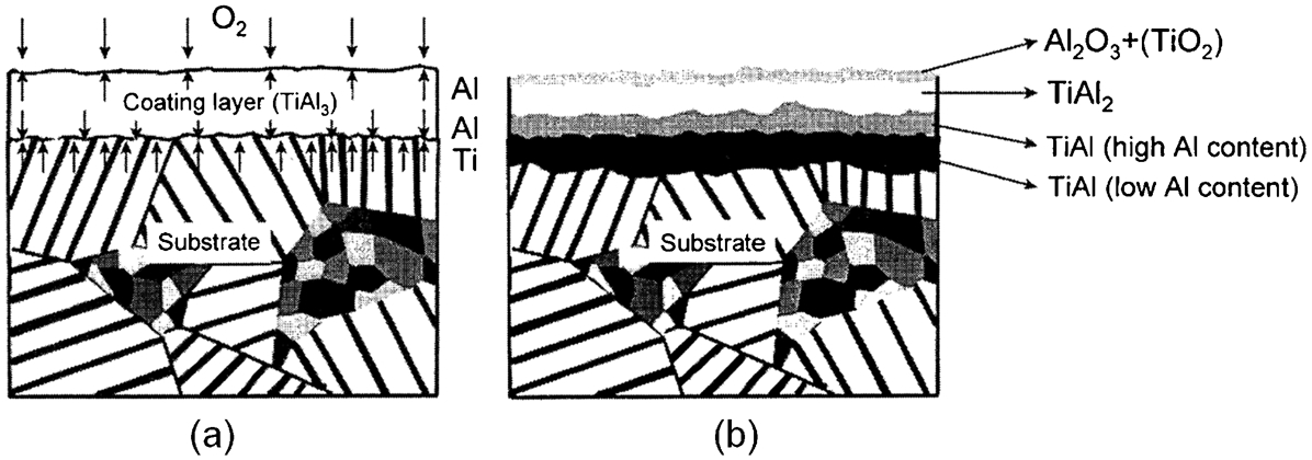
Schematic illustration of oxidation process for γ-TiAl specimen aluminised at 800°C for 3 h, a early stage of oxidation process and b morphology after oxidation 61
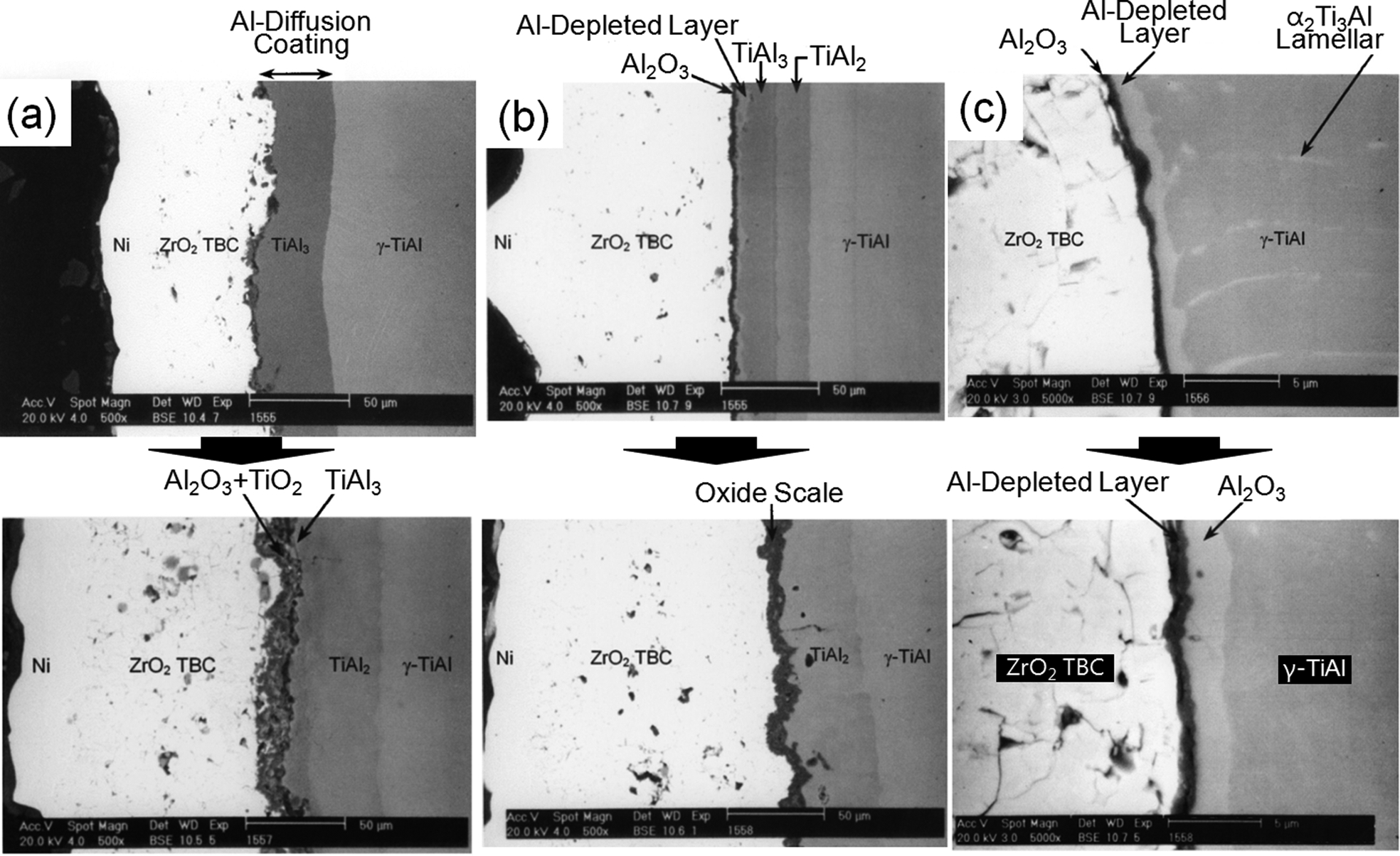
Gauthier et al. 62 reported that the TiAl3 coating on Ti–50Al (at.-%) by the pack-cementation process (5 wt-%Al, 0·5wt-%NH4Cl and the balance of Al2O3 with Ar/H2 carrier gas) showed excellent isothermal oxidation resistance at 900°C in air for up to 100 h, forming a protective and adherent oxide scale composed mostly of Al2O3. Figure 28a shows the cross-sectional microstructure of an aluminised γ-TiAl alloy where a single TiAl3 layer is formed. During isothermal oxidation, the TiAl3 layer interdiffused rapidly with the γ-TiAl substrate and the depletion of Al in the TiAl3 layer resulted in the formation of a TiAl2 layer at the TiAl3–TiAl interface as shown in Fig. 28b and c .
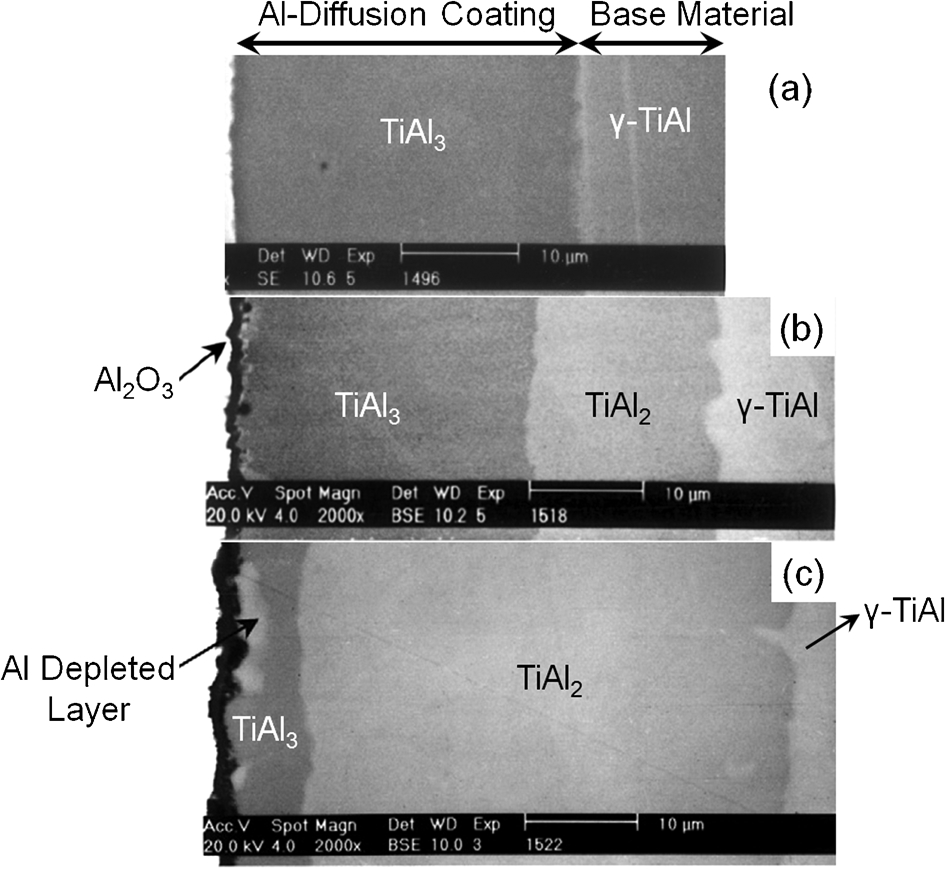
SEM cross-section of a as-aluminised γ-TiAl at 800°C for 5 h in a low Al-activity pack b after 10 h and c after 100 h of isothermal oxidation in air at 900°C 62
Figure 29 shows SEM micrographs of oxides formed on the aluminised γ-TiAl alloy after 300 h of isothermal oxidation tests in air at 900°C. In Fig. 29a , the TiAl3 has completely transformed to TiAl2, and the Al2O3 layer is no longer maintained due to the Al depletion. In Fig. 29b , significant cracking occurred in the brittle TiAl2 and crack propagation induced spallation of the oxide scale from the Al2O3–TiAl2 interface. The TiAl3 coating layer that formed by aluminising is quite brittle and has poor cracking resistance. 62 Thus, the brittle nature of the TiAl3 coating, due to its low-symmetry crystal structure and tetragonal DO22 structure, 59 may preclude its use for improving the oxidation resistance of TiAl alloy under thermal cyclic conditions. 59
Cross-sectional SEM micrographs of the oxide scale formed on the Al diffusion-coated γ-TiAl alloy after 300 h of isothermal oxidation in air at 900°C, a sound coating b cracked TiAl2 layer 62
Effect of ternary element on oxidation behaviour of aluminised γ-TiAl alloy
The properties of the coating layer formed by PC process are influenced by the alloy composition of the substrate because the PC technique is generally based on inter-diffusion between the deposit and the substrate material. 59 This alloy effect on the properties of an aluminised TiAl3 coating on γ-TiAl was studied with the addition of four elements (Nb, Cr, Fe and V). Among the alloying elements evaluated, Nb showed the most positive effects on the thickness, microstructure, and stability of the coating layer. 59 The addition of a small amount of Nb or Cr improved significantly the aluminising kinetics of TiAl alloys by increasing the solid-state diffusion of Al through the formation of a stable TiAl3 layer. 63 The coatings formed on the TiAl alloys with the addition of Nb or Cr had much fewer cracks compared to those formed on the binary TiAl alloy (Fig. 30), indicating that alloying elements could improve the toughness of the coatings. 63
Optical images of the aluminide coating layer after aluminising at 950°C for 6 h 63
Figure 31 represents the cyclic oxidation behaviour of the aluminised Ti–48Al (at.-%) alloys with and without ternary element addition. In Fig. 31a , except for Ti–48Al–2Nb (at.-%), an excessive increase of weight gain was observed in all the aluminised specimens possibly due to the formation of TiO2 protrusions on the surface. 64 The oxidation resistance of aluminised Ti–48Al–xNb (at.-%, x = 1, 2, 4 and 6) alloys increased with increasing amounts of Nb, as shown in Fig. 31b , and there were no TiO2 protrusions or large increases in weight. The coating that formed on all Ti–48Al–xNb (at.-%) alloys was TiAl3 regardless of the Nb content. With an increase in Nb content from 1 at.-% to 6 at.-%, the TiAl3 layer became thicker and had finer grains. The grain refinement of the TiAl3 coating improved its ductility and oxidation resistance under cyclic oxidation environment by preventing spallation. 64
Weight change curves for aluminised TiAl alloys during cyclic oxidation at 1000°C 64
The oxidation resistance of Ti–48Al (at.-%) and Cr-modified Ti–48Al (at.-%) alloys prepared by using two different PC processes was examined. 59 One was a simple aluminide coating and the other was a Cr+Al two-step PC process (pack aluminised after pack chromising). For the simple aluminising process shown in Fig. 32a , the addition of Cr in Ti–48Al (at.-%) alloy improved its oxidation resistance by helping to form a fine layered microstructure of TiAl3. During pack aluminising, the tendency of grain refinement by Cr addition was similar to that by Nb addition. 64 However, the weight change of aluminised Ti–48Al (at.-%) without Cr showed an abnormal increase followed by spallation. Although the oxidation resistance was improved for all the aluminised Ti–48Al–xCr (at.-%, x = 1, 4 and 6) alloys, there was a propensity that the weight increased abnormally at different times with different Cr concentrations, and the time to abnormal weight increase in Fig. 32a coincided with the time for TiO2 protrusion at the surface. 59 The cyclic oxidation resistance of Cr+Al coated Ti–48Al (at.-%) alloy was five times better than that of simple pack aluminised TiAl alloy (Fig. 32b ) in terms of the onset of coating spallation. 59 The improved oxidation resistance resulted from the transformation from the Al4Cr outer layer and TiAl inner layer, to Ti(Al, Cr)3 with an L12 structure with much better ductility and superior oxidation resistance in cyclic oxidation tests. 59
Cyclic oxidation test result of a aluminised TiAl–xCr (at.-%) alloys and b Cr+Al two-step coated TiAl at 1000°C 59
Oxidation behaviour of γ-TiAl alloy with overlay MCrAlY coating
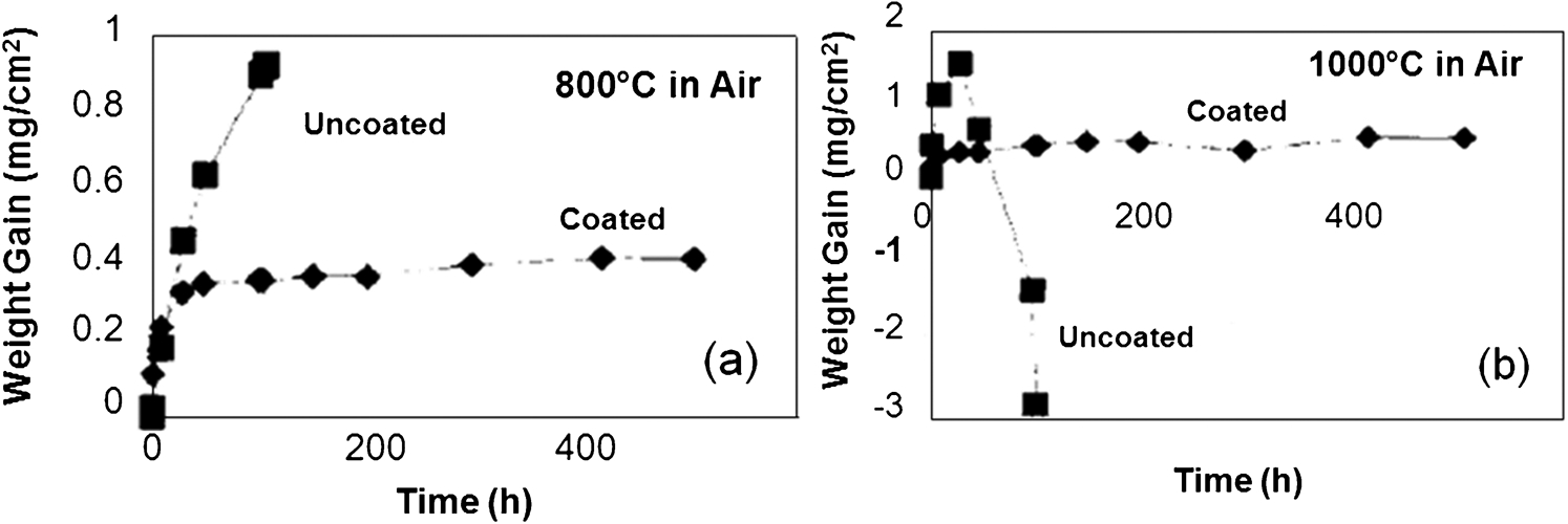
MCrAlY (M = Co, Ni, or both) coating has been used as a corrosion and oxidation resistance coating or a bond coat in TBC systems for superalloy components in gas turbine hot sections. 65,66 The schematic illustration of a TBC system on a first stage turbine blade with temperature profile is shown in Fig. 33. In the layered structure, the bond coat prohibited oxidation of the substrate by forming a thermally grown oxide (TGO) layer 67,68,70 between the bond coat and the top coat. For the same working environment, MCrAlY overlay coatings should also provide protection for the TiAl alloy. 3,71,72 Oxidation resistance of a Ti–47Al (at.-%) alloy coated with a 50–60 μm APS (Air Plasma Spraying) Co–32Ni–21Cr–8Al–0·5Y (wt-%) overlay coating was investigated. 32 The bare Ti–47Al (at.-%) withstood isothermal oxidation up to 800°C in air following a parabolic rate law, but the cyclic oxidation resistance of the bare TiAl was poor due to spalling of the Al2O3 layer. Also the parabolic rate changed into a linear rate above 800°C. The CoNiCrAlY coating was found to be a promising candidate to provide oxidation resistance to TiAl because the APS CoNiCrAlY decreased the weight gain remarkably and converted the oxidation behaviour into a parabolic relationship with a lower rate constant at temperatures over 800°C. Moreover, the coating layers and the oxide scales did not spall under cyclic condition.
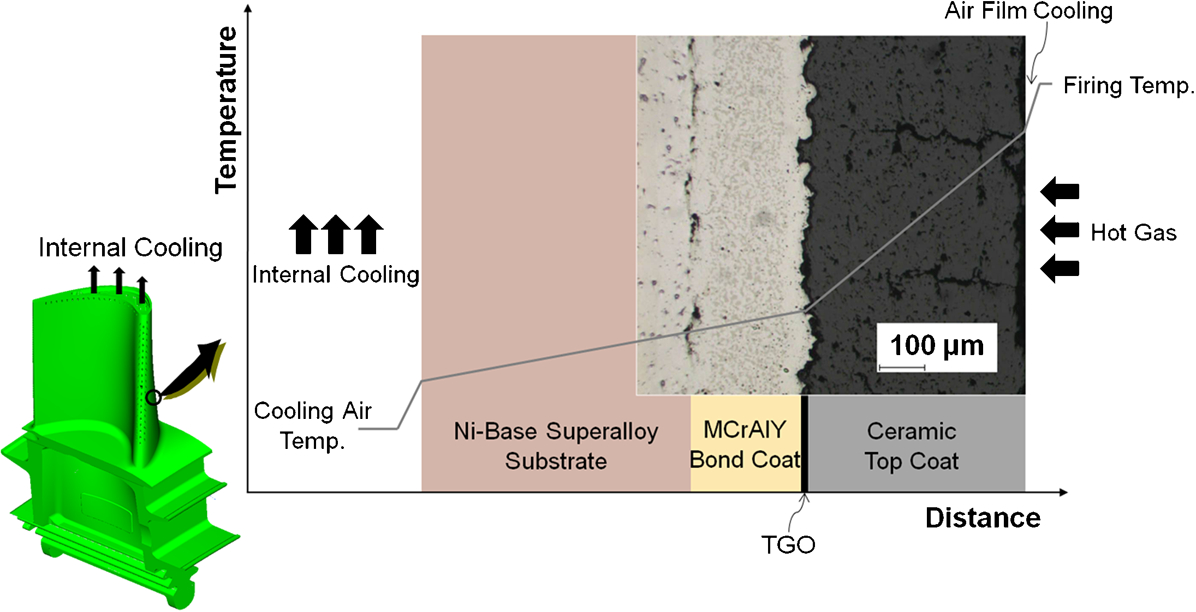
Schematic temperature profile across the thermal barrier coating (TBC) system in a first stage blade 69
Z. Tang et al. 3,71,72 have studied the effect of Co–30Cr–6Al–0·5Y and Ni–30Cr–6Al–0·5Y overlay coatings on oxidation resistance of Ti–50Al (at.-%) at 900–1000°C in air. Figure 34 shows the results of the isothermal oxidation kinetics of Ti–50Al (at.-%) with and without MCrAlY coatings. Both CoCrAlY and NiCrAlY coatings remarkably improve the oxidation resistance of γ-TiAl owing to the formation of a protective Al2O3 scale. 3 (CoCrAlY performed better than NiCrAlY under various conditions). However, negative effects in terms of mechanical properties were also revealed during an examination of cross-sectional microstructures and hardness profiles of the oxidised samples.
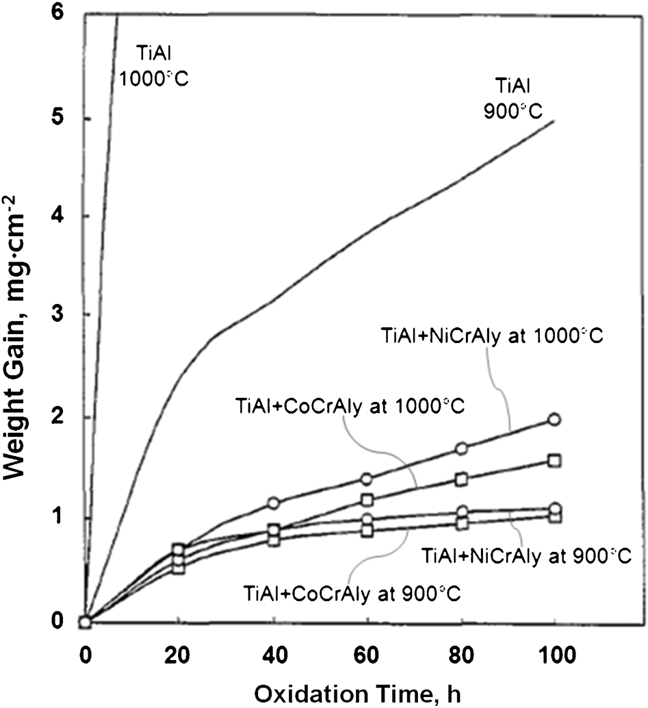
Oxidation kinetics of Ti–50Al (at.-%) with MCrAlY coatings at 900 and 1000°C 3
Figure 35 shows a cross-sectional view of the microstructures of γ-TiAl with CoCrAlY and NiCrAlY overlay coatings after 100 h of oxidation at 900°C in air, while Fig. 36 display the elemental and micro-hardness profiles across the coating–substrate interface of the two coating systems. Owing to outward-diffusion of Ti and Al and inward-diffusion of Ni and Co, 3,72 two new diffusion layers were formed between the MCrAlY coatings and the substrate, one of them being AlNi2Ti or AlCo2Ti ternary intermetallics and the other being unknown Ni–Al–Ti or Co–Al–Ti ternary phases. Also, many Kirkendall voids formed at the coating/substrate interface which would deteriorate the coating adherence to the substrate. 3 The diffusion layers which were very hard as indicated by the microhardness values in Fig. 36 are detrimental to the mechanical properties. 3,72 The formation of TiO2 was still inevitable on both of CoCrAlY and NiCrAlY coatings (Fig. 37a ). 3 Cracks appeared in the CoCrAlY coating after 100 cycles of oxidation at 1000°C and some cracks further extended to the substrate (Fig. 37b ).
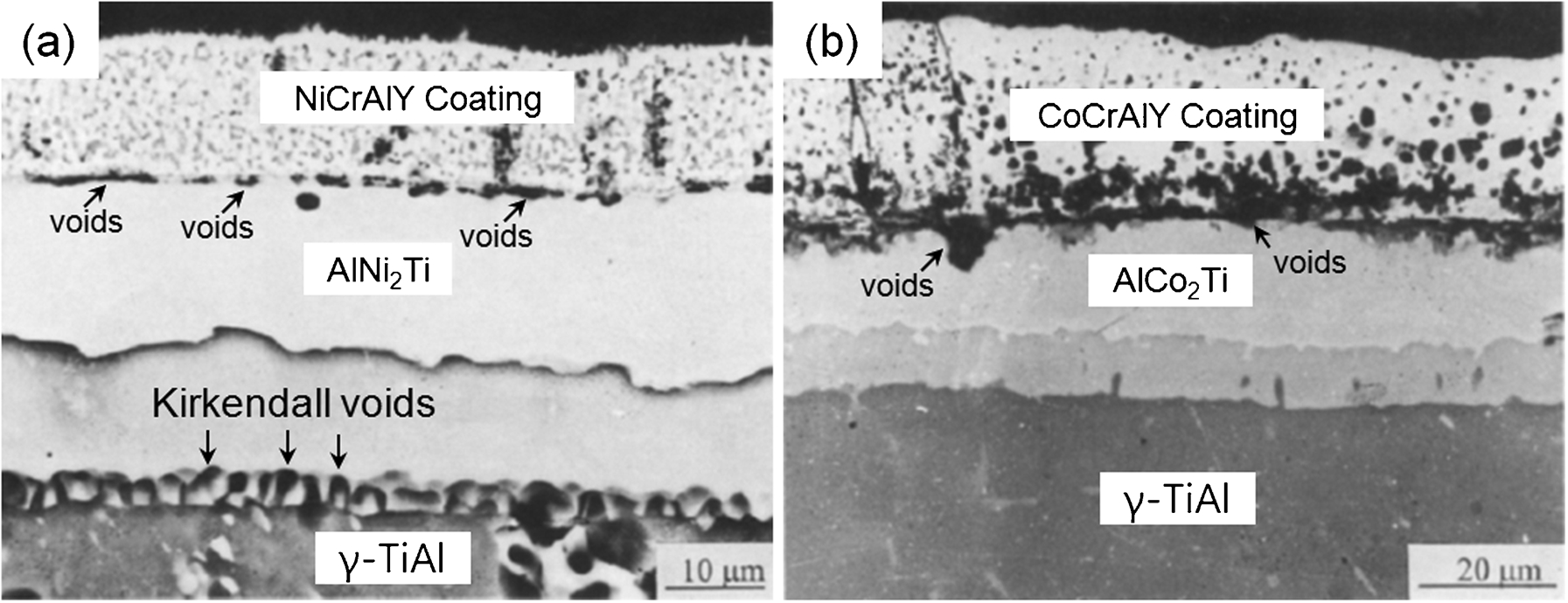
Cross-sectional view of the microstructure of γ-TiAl with a NiCrAlY coating and b CoCrAlY coating after 100 h of oxidation at 900°C in air 71
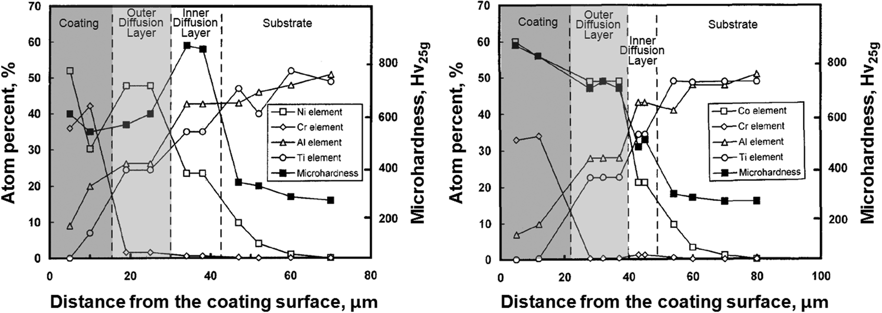
Element and micro-hardness profiles across the coating–substrate interface for TiAl with a NiCrAlY coating and b CoCrAlY coating after 100 h of oxidation at 900°C 71
Surface morphologies a and cross-sectional microstructure b of TiAl with CoCrAlY coating after 100 cycles of oxidation at 1000°C 72
To prevent inter-diffusion between the MCrAlY overlay and the γ-TiAl substrate, an intermediate diffusion barrier has been employed. 73,74 A Ti–48Al–2Cr–2Nb (at.-%) alloy with a Al/Al2O3/NiCoCrAlY coating system provided better oxidation resistance than the alloy with only monolithic NiCoCrAlY (Ni–32Co–20Cr–8Al–0·5Y (wt-%) by arc ion plating) coating under isothermal oxidation at 900°C. With Al/Al2O3 diffusion barriers, both the outward-diffusion of Ti and inward-diffusion of Ni and Co were suppressed. The dense and uniform scale consisting only of Al2O3 was formed on the coating surface. No diffusion zones containing brittle intermetallic phases such as AlCo2Ti and AlNi2Ti were formed. It was also reported that an inward-diffusion of Ni was significantly suppressed between γ-TiAl alloy and NiCrAlY overlay coating by introducing an intermediate layer of an arc ion plated Cr2O3 as a diffusion barrier. 74 In the absence of Cr2O3 interlayer, apparent inward-diffusion of Ni from NiCrAlY coating to the γ-TiAl substrate occurred and at least three inter-diffusion zones were developed. 74
Oxidation behaviour of γ-TiAl alloy with Ti–Al–X coating
Although there have been positive effects on the oxidation resistance with conventional protective coatings such as aluminides and MCrAlY coatings, these coatings still encounter limitations due to compatibility. MCrAlY was successfully used to protect Ni-, Fe-, Co-based superalloys, but it reacted extensively with TiAl alloys and formed brittle coating/substrate reaction zones due to severe inter-diffusion. 26,71,72 Aluminising treatments resulted in the surface formation of the TiAl3 and TiAl2 phases, which were brittle and exhibited mismatch in the coefficient of thermal expansion (CTE) with γ-TiAl alloys. 26 Therefore, coating materials should be selected by considering not only the oxidation resistance, but also the mechanical properties and the chemical compatibility with the substrate. 26,75
Ti–50Al–10Cr coating
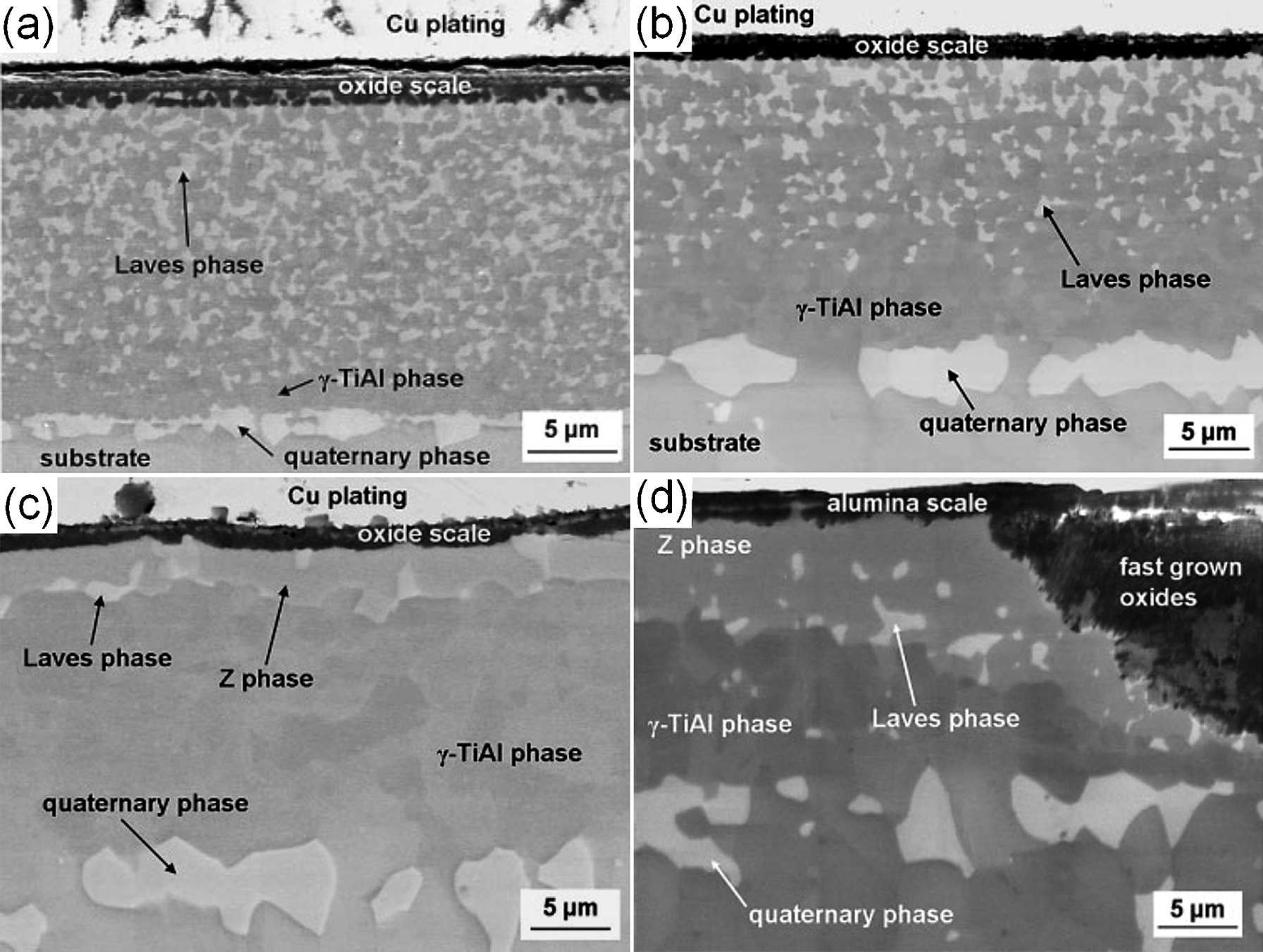
Magnetron sputtered Ti–50Al–10Cr (at.-%) coating consisting of γ-TiAl and TiAlCr Laves phases provided excellent oxidation protection for γ-TiAl (Ti–50Al, at.-%) alloy owing to the formation of an adherent Al2O3 scale. 71,72 Figure 38 shows cross-sectional microstructures of TiAl with TiAlCr coating after isothermal and cyclic oxidation. The dark TiAlCr Laves phase is surrounded by a continuous bright γ-TiAl matrix. Compared to the severe inter-diffusion and the frequent Kirkendall voids in the MCrAlY coated TiAl system (Fig. 35), the inward-diffusion of Cr was limited, and no Kirkendall voids were found at the coating/substrate interface after long-term exposure of Ti–50Al–10Cr (at.-%) coated TiAl. 72
Cross-sectional microstructure of γ-TiAl with Ti–50Al–10Cr (at.-%) coating after a 1000 h of oxidation at 900°C, b 100-cycles of oxidation at 1000°C 72
The oxidation behaviour of Al2O3, aluminide, CoCrAlY, and Ti–50Al–10Cr (at.-%) coatings on the same Ti–50Al (at.-%) alloy was compared during cyclic oxidation tests at 900 and 1000°C. 72 Al2O3 coatings had limited potential to improve the cyclic oxidation resistance of TiAl due to rapid spallation. Although aluminide and CoCrAlY coatings remarkably improved the cyclic oxidation kinetics of TiAl due to the formation of adherent Al2O3 scales, cracks formed in these two coatings after cyclic oxidation. Among the coatings, TiAlCr was found to exhibit the best positive effect owing to the similar CTEs between TiAlCr and TiAl alloy, as well as a relatively slow diffusion of Cr in the TiAl alloy, and a beneficial two-phase microstructure (γ+Laves phase), which was most compatible with TiAl alloy. 72
Ti–51Al–12Cr coating
If a TiAl alloy-based coating could form a continuous Al2O3 scale, it would be an ideal coating material for γ-TiAl alloys because they are most chemically and mechanically compatible with the substrate. 26 Perkins and Meier et al. discovered that Ti–Al–Cr alloys with 8–10 at.-%Cr were alumina formers in air in the temperature range of 800–1300°C. 26 Research by the NASA Lewis Research Center (currently, NASA John H. Glenn Research Center at Lewis Field) revealed that a Ti–Al–Cr composition yielding a microstructure consisting of primarily a γ phase and a Ti (Cr, Al)2 (Laves) phase was capable of forming a continuous Al2O3 scale despite a lower Al content of 37–42 at.-%, and the Laves phase was a key to oxidation resistance. 26 A region of alumina-forming two-phase Ti–Al–Cr compositions was also identified in the same research. In particular, a low-pressure plasma sprayed (LPPS) Ti–51Al–12Cr (at.-%) coating consisting of γ-TiAl+Laves phase demonstrated excellent chemical and thermal compatibility with a Ti–48Al–2Cr–2Nb (at.-%) substrate during oxidation tests at 800 and 1000°C in air (Fig. 39). 26 The improved compatibility was believed to have been due to the similarity in the CTE between the substrate and two-phase coating, and the beneficial effect of ductile γ-TiAl matrix encompassing the extremely brittle yet oxidation resistant Laves phase. 26
Weight-gain oxidation data for low-pressure plasma sprayed (LPPS) Ti–51Al–12Cr (at.-%) coated and uncoated Ti–48Al–2Cr–2Nb (at.-%) at a 800 and b 1000°C in air 26
The oxidation resistance of magnetron sputtered Ti–51Al–12Cr (at.-%) coatings on Ti–45Al–8Nb (at.-%) substrate was also investigated under cyclic oxidation conditions. 26,76–78 Ti–51Al–12Cr (at.-%) coating provided excellent oxidation resistance at temperatures between 750 and 900°C, as shown in Fig. 40. At 950°C, the Ti–Al–Cr coatings provided reasonable protection for up to 350 cycles before breakaway oxidation occurred while the oxide scale on the uncoated sample readily spalled after a few cycles. 15 The degradation of Ti–Al–Cr coating on Ti–45Al–8Nb (at.-%) alloy at 900°C was primarily due to the inward-diffusion of Cr from the coating into the substrate 15 and the depletion of Al in the coatings during long-term exposure. Figure 41 shows degradation process in the Ti–51Al–12Cr (at.-%) coating on Ti–45Al–8Nb (at.-%). As exposure time increased, the Laves phases were dissolved in the coating due to the depletion of chromium. Also, the growth of alumina oxide caused the depletion of Al in the coating adjacent to the oxide scale leading to the transformation of the γ-phases into new cubic Ti–Al–O phases which were commonly referred to as Z-phase 78–82 (Fig. 41c ). The degradation of the Z-phase resulted in rapid oxidation, 78 as shown in Fig. 41d .
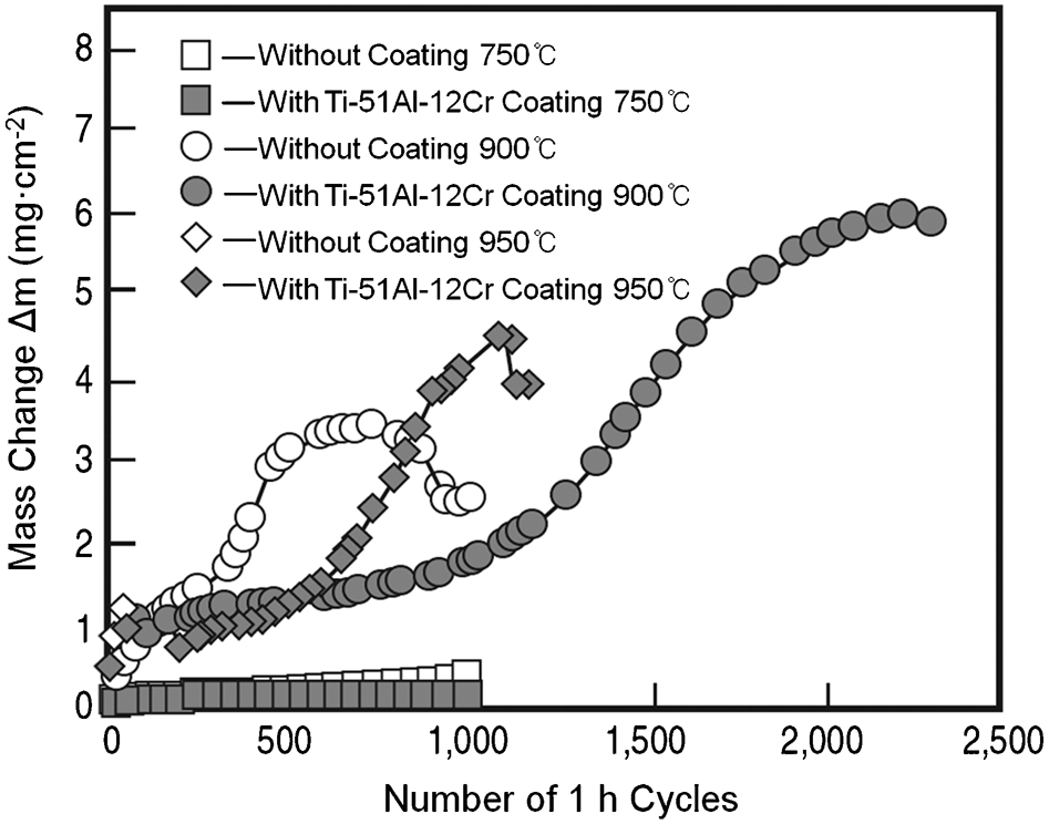
Mass change versus number of 1-h cycles of uncoated and Ti–Al–Cr-coated Ti–45Al–8Nb (at.-%) exposed to air at temperatures between 750 and 950°C 15
SEM micrographs of the Ti–51Al–12Cr (at.-%) coating on Ti–45Al–8Nb (at.-%) exposed to air a at 900°C for 10 cycles, b at 900°C for 120 cycles, c at 950°C for 120 cycles, d at 900°C for 700 cycles 15
Al–21Ti–23Cr coating
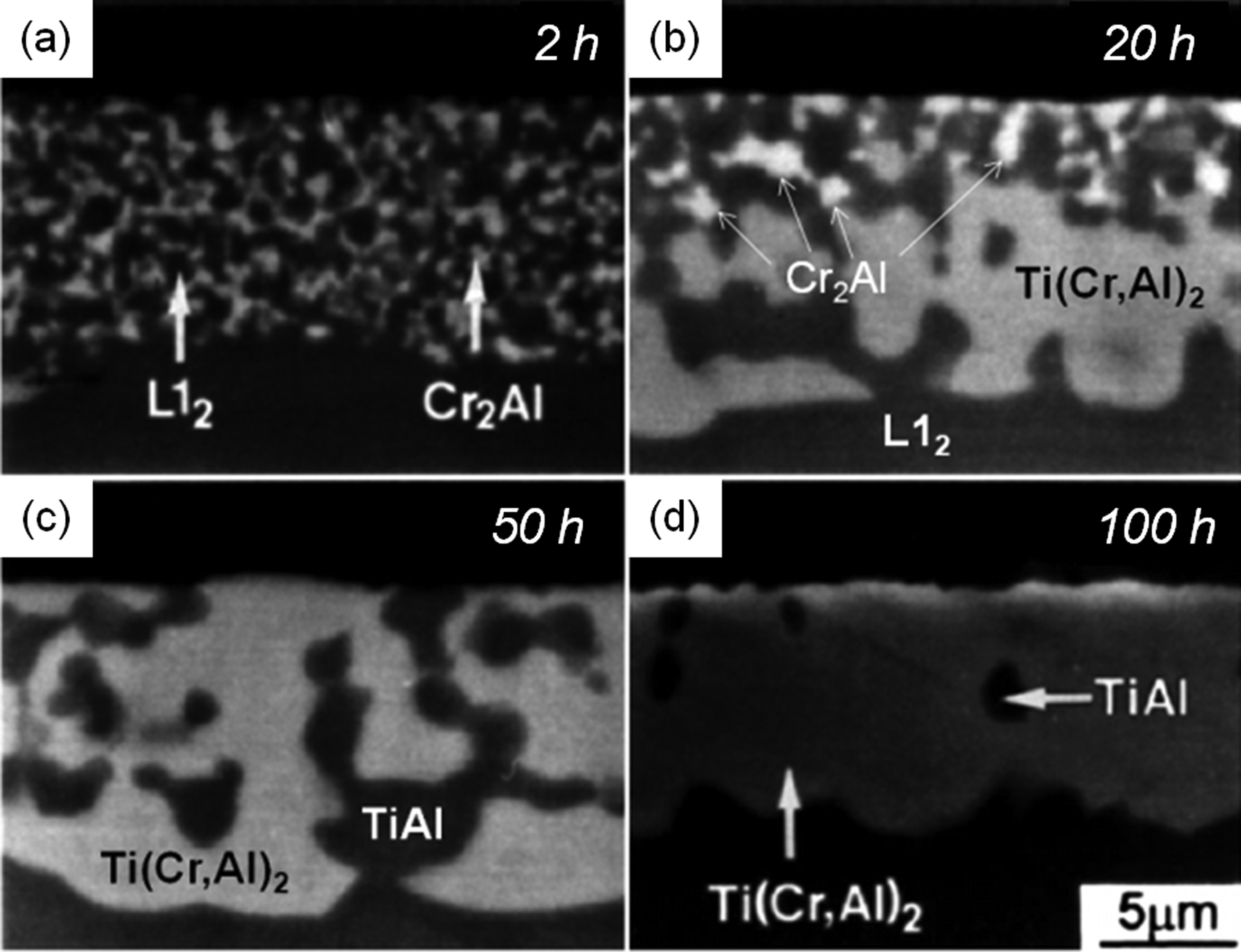
Al–21Ti–23Cr (at.-%), with an L12 (Al, Cr)3 Ti-based two-phase structure, was applied onto Ti–48Al (at.-%) alloy using magnetron sputtering. 75,85 Figure 42 shows the parabolic rate constant k p obtained from isothermal oxidation curves of Ti–48Al (at.-%) coated with Al–21Ti–23Cr (at.-%) and CoCrAlY at 800, 900 and 1000°C for 100 h. The as-deposited amorphous Al–21Ti–23Cr (at.-%) coating transformed to L12 Cr2Al, and Ti (Cr, Al)2 phases after oxidation. Figure 43 shows the microstructural evolution of a coating layer with increasing exposure time at 1000°C. The initial L12+Cr2Al phases (Fig. 43a ) were transformed to γ+Ti (Cr, Al)2 phases after 100 h (Fig. 43d ). The excellent oxidation resistance of Al–21Ti–23Cr (at.-%) was attributed to the Ti (Cr, Al)2 phase which formed a protective Al2O3 layer on the coating surface. 85 Also it was believed that once a protective Al2O3 scale was established on Al–21Ti–23Cr (at.-%), the high Al content in the coating made the scale continuously grow providing longer term oxidation resistance. 85
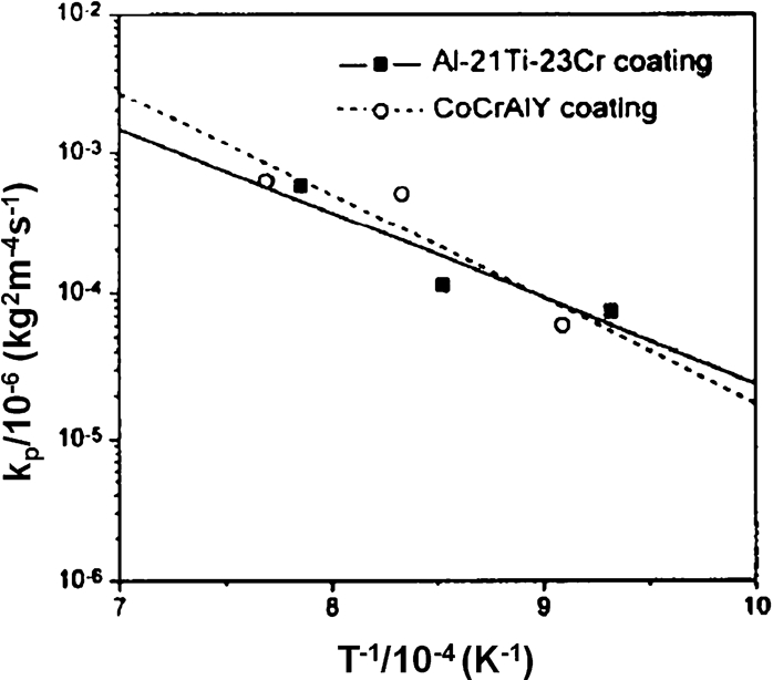
Parabolic rate constants for the oxidation of Ti–48Al (at.-%) coated with Al–21Ti–23Cr (at.-%) film and TiAl with CoCrAlY film 75
Cross-sections of Al–21Ti–23Cr (at.-%) coating oxidised at 1000°C for a 2 b 20 c 50 and d 100 h 75
Ti–Al–X (X = Nb, Cr) coating
The oxidation behaviour of magnetron sputtered Ti–Al–X (X = Cr, Nb) coatings with different compositions (Table 2) was studied. 83 Metastable as-sputtered Ti–Al–Nb and Ti–Al–Cr coatings were transformed to two-phase microstructures of γ-TiAl with Ti–Al–Cr or Ti3Al (Table 2) during high temperature exposure. Figure 44 shows the results of isothermal oxidation weight gain for coated and uncoated Ti–48Al–2Cr–2Nb (at.-%) in air at 900°C. The two Nb-containing γ-TiAl+Ti3Al phase coatings just slightly improved oxidation resistance, and the main failure mechanism was the spallation of the coating during cooling due to CTE mismatch. 83 For the Cr-containing γ-TiAl+Laves phase coatings, oxidation resistance was improved with Cr content (Fig. 44b ). After 100 h of exposure at 900°C, the oxide scales were composed of mixed rutile and alumina, and the morphology of the oxide scale was strongly influenced by the Nb or Cr content of the alloy. 83
Weight gain in the isothermal oxidation at 900°C in air for uncoated Ti–48Al–2Cr–2Nb (at.-%) alloys and coated with a Ti–Al–Nb and b Ti–Al–Cr 83
Metallic phase composition of the Ti–Al–X coatings on Ti–48Al–2Cr–2Nb (at.-%) after 100 h of exposure at 900°C 83
The effect of ternary or quaternary elemental additions on the magnetron sputtered γ-TiAl-based coatings was also investigated. 84 The micro-alloyed γ-TiAl–X (X = Cr, Nb, Ta, Mo, Ag, Si) coatings were found to be promising for oxidation protection at 900°C due to grain size refinement of the oxide scale and preferential nucleation of the Al2O3 on the coating surface. 84 However, the synergistic effect was not observed in the quaternary coatings such as TiAl (Cr, Nb), TiAl (Ta, Nb),TiAl (W, Cr) and TiAl (Ag, Si). 84
Oxidation behaviour of γ-TiAl alloy with other coatings
Ti–Al–Cr–Y–N nitride coatings also exhibited excellent oxidation resistance at 750°C for up to 3000 h. 76,77 However, the nitride coatings were not suitable for TiAl alloys at temperatures above 850°C for long-term applications. 78 This was because the Ti–Al–Cr–Y–N layer would be completely oxidised after very short exposure time. Si-based coatings exhibited excellent oxidation resistance due to the Ti-rich stable Ti5Si3 phase, which was believed to have transformed from Si-rich initial phases, 78 through the inter-diffusion between the substrate and the Si-based coating (Fig. 45). The oxidation mechanism of Si-based coatings was a simultaneous outer TiO2 scale growth and the oxidation of Ti5Si3 phase at grain boundaries forming a porous inner oxide scale (Fig. 45c ) consisting of mainly TiO2 and SiO2 in the subsurface region below a relatively dense TiO2 scale. 78
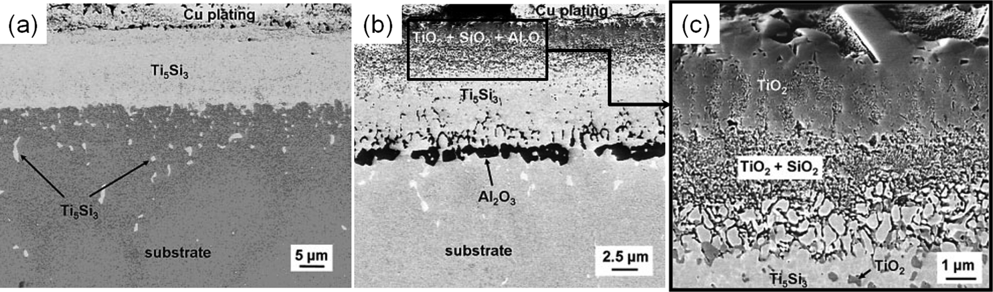
SEM micrograph of Si-coated TiAl a pre-treated at 1000°C for 100 h under high vacuum conditions (10−6 mbar), b and c exposed to air at 950°C for 1000 cycles 78
Oxidation behaviour of beta-gamma TiAl alloy with NiCrAlY coating
D.J. Kim et al. investigated the cyclic oxidation behaviour of NiCrAlY-coated TiAl–4Nb–3Mn (at.-%) 86 and TiAl–2Nb–2Mo (at.-%) 87 beta gamma alloys between room temperature and 1000°C for up to 800 cycles in air. Figure 46 shows cross-sectional microstructures with increasing thermal cycle for the TiAl–4Nb–3Mn (at.-%) alloy. During cyclic oxidation, a TiN layer formed at the interface between NiCrAlY and the TiAl–4Nb–3Mn (at.-%) alloy, and the thickness of the TiN layer increased with the number of cycles by expanding in both the inward and outward directions. The porous structure of the plasma sprayed NiCrAlY coating allows N2 ingression to the interface, and the nitrogen content in the substrate was relatively high even in the as-coated condition, as shown in Fig. 47. Therefore, the TiN formation resulted from the nitrogen effect as well as Ti reacting with the outwardly diffused N from the substrate. The TiN interfacial layer acted as a barrier which blocked inward Ni diffusion as well as outward Ti diffusion once the TiN layer reached a certain thickness. 86,87
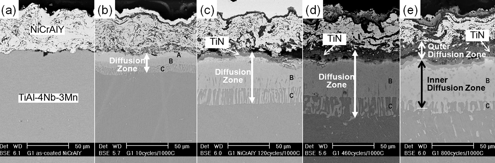
Microstructure of NiCrAlY-coated TiAl–4Nb–3Mn (at.-%) alloy after a as-coated b 10 cycles c 120 cycles d 460 cycles and e 800 cycles at 1000°C 86
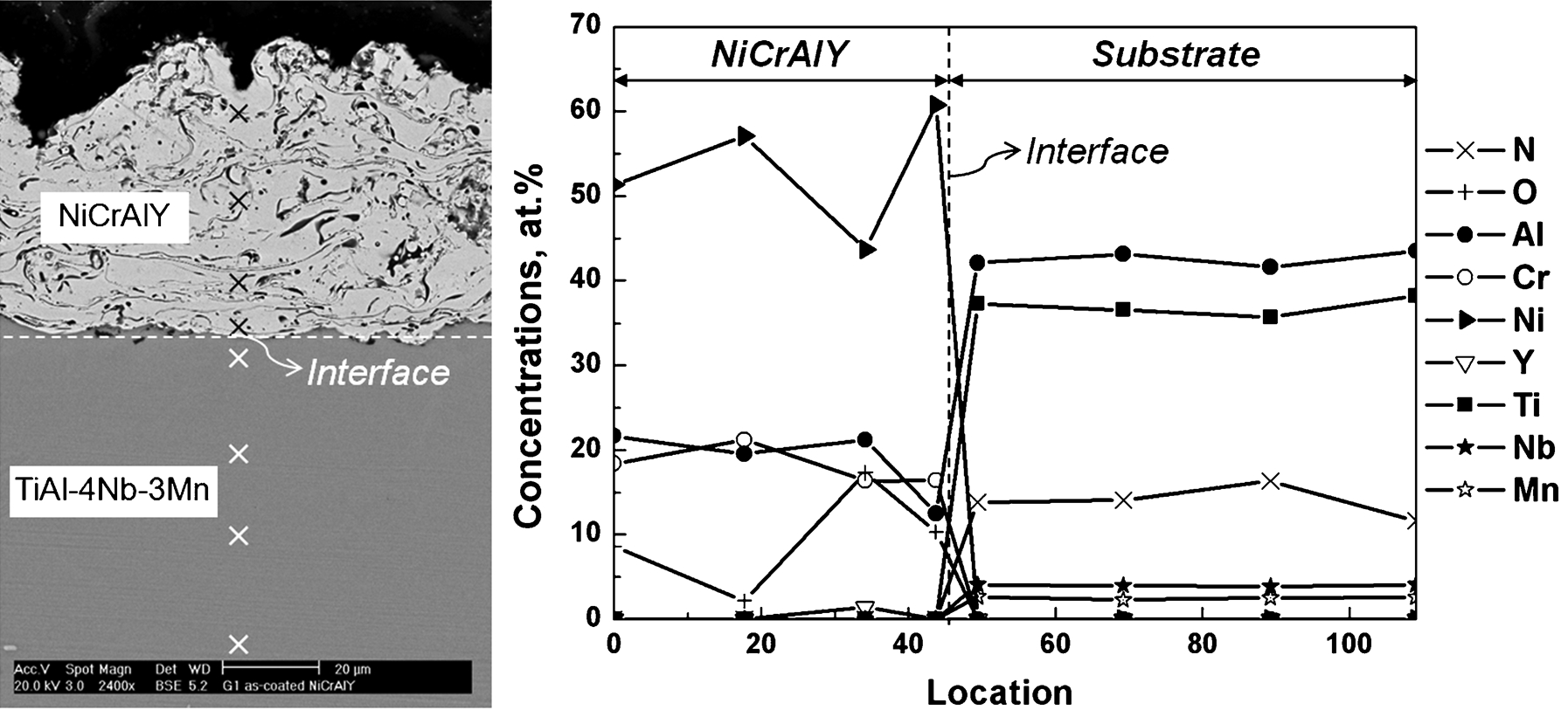
NiCrAlY-coated TiAl–4Nb–3Mn (at.-%) alloy in as-coated condition, a cross-sectional SEM micrograph, b compositional profiles 86
Another feature in cyclic oxidation of the NiCrAlY-coated beta gamma alloys at 1000°C was a severe inward-diffusion of Ni, which led to the formation of an inner-diffusion zone. 86,87 Both the TiAl–4Nb–3Mn (at.-%) and the TiAl–2Nb–2Mo (at.-%) alloys formed Ni2TiAl/NiAlTi/(NiAlTi+TiAl) layers of diffusion zone mainly due to the inward Ni diffusion. In the case of the TiAl–4Nb–3Mn (at.-%) alloy in Fig. 46, the outermost Ni2TiAl layer (A in Fig. 46b ) was gradually converted to TiN phases and the alternating NiAlTi+TiAl (C) layer gradually disappeared with an expansion of NiAlTi (B) as more Ni diffused inwardly. Figure 48 shows a schematic illustration of diffusion process after 800 cycles based on the results of microstructural and compositional analyses using SEM/EDS. 86
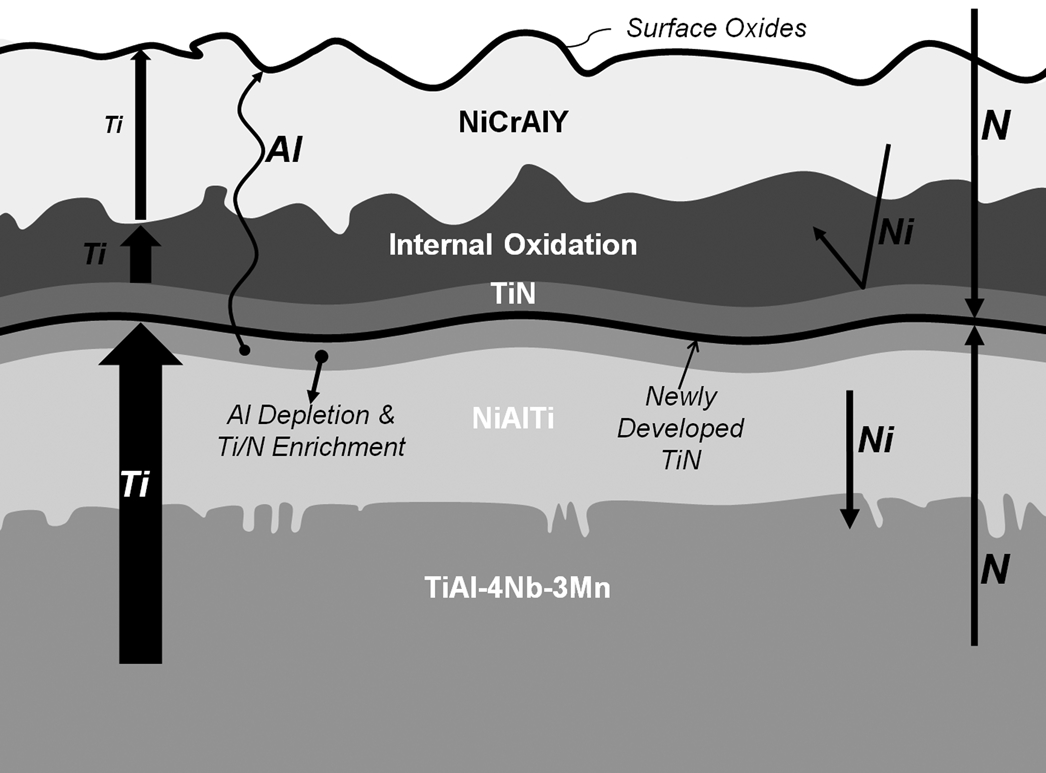
Schematics for the diffusion processes in NiCrAlY-coated TiAl–4Nb–3Mn (at.-%) alloy during cyclic oxidation at 1000°C after 800 cycles 86
Under the same NiCrAlY coating and oxidation test conditions, the TiAl–2Nb–2Mo (at.-%) alloy exhibited very similar oxidation kinetics and mechanism to those of the TiAl–4Nb–3Mn (at.-%) alloy. 87 Severe inter-diffusion also occurred in the TiAl–2Nb–2Mo (at.-%) alloy, as illustrated in Fig. 49, mainly due to the inward-diffusion of Ni. Ni diffused not only inwardly but also outwardly, leading to the formation of blocky NiO phases on top of the surface, as shown in Fig. 50, which was also a common mechanism between the TiAl–4Nb–3Mn (at.-%) and the TiAl–2Nb–2Mo (at.-%) alloys. Diffusion of Mo from dissociated α2 lamellae underneath the diffusion zone led to the formation of bright globular phases in the inner-diffusion zone and the widening of the grain boundary regions in the substrate. 87 The continued outward-diffusion of Al through the TiN layer led to the formation of an Al depleted layer and voids underneath the TiN layer after 460 cycles, as illustrated in Fig. 49. 87
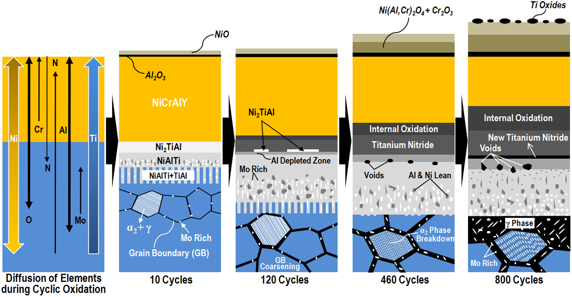
An illustration for the diffusion processes in NiCrAlY-coated TiAl–2Nb–2Mo (at.-%) alloy during cyclic oxidation at 1000°C. 87
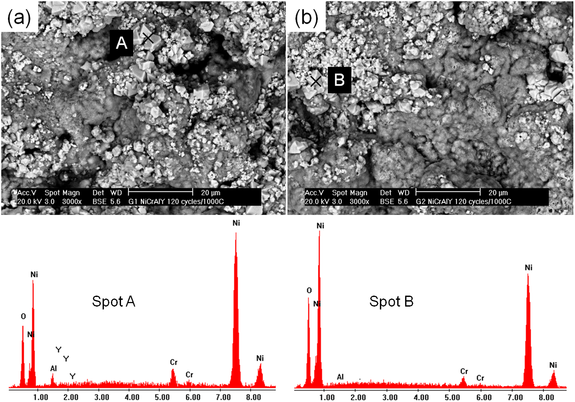
Surface morphologies of the oxidised NiCrAlY coating on a TiAl–4Nb–3Mn (at.-%) and b TiAl–2Nb–2Mo (at.-%) alloys 87 after 120 cycles at 1000°C and corresponding EDS spectra
Figure 51 shows the cyclic oxidation behaviour of NiCrAlY-coated TiAl–4Nb–3Mn (at.-%) and TiAl–2Nb–2Mo (at.-%) alloys at 1000°C in air. The cyclic oxidation kinetics of other TiAl alloys with aluminising 64 and other coatings 72,85,88 tested at the same temperature are plotted together for comparison. It is noted that the duration for each cycle is different for various cases. The weight of NiCrAlY-coated TiAl–4Nb–3Mn (at.-%) and TiAl–2Nb–2Mo (at.-%) alloys began to drop before 10 cycles and decreased rapidly after 200 cycles. At the beginning of oxidation, the increasing rates of the TiAl–4Nb–3Mn (at.-%) and the TiAl–2Nb–2Mo (at.-%) alloys were considerably high compared to the others, as shown in Fig. 51a . The weight drop during cyclic oxidation was generally associated with the spallation of top surface probably due to the thermal stress between the oxides and the coating materials. However, the spallation in both the TiAl–4Nb–3Mn (at.-%) and the TiAl–2Nb–2Mo (at.-%) cases occurred on the circumferential side of the specimen, as shown in Fig. 51b . The spallation after only a few thermal cycles originated from the fact that only the top and bottom sides of the samples were facing the spray gun, and the circumferential side had a relatively thin and less-adherent NiCrAlY layer during the coating process due to lower spray angle. 87 Although there was a continuous weight loss after 120 cycles, both the top and bottom surfaces of the specimens remained in contact with the substrate until 800 cycles, as shown in Fig. 51b . However, the severe inward- and outward-diffusion in both the TiAl–4Nb–3Mn (at.-%) and the TiAl–2Nb–2Mo (at.-%) alloys resulted in the consumption of more than a third of the NiCrAlY coating after 800 cycles, as shown in Fig. 46e , suggesting the need for applying a diffusion barrier coating at the interface between the NiCrAlY coating and the TiAl–4Nb–3Mn (at.-%) or the TiAl–2Nb–2Mo (at.-%) beta gamma alloys.
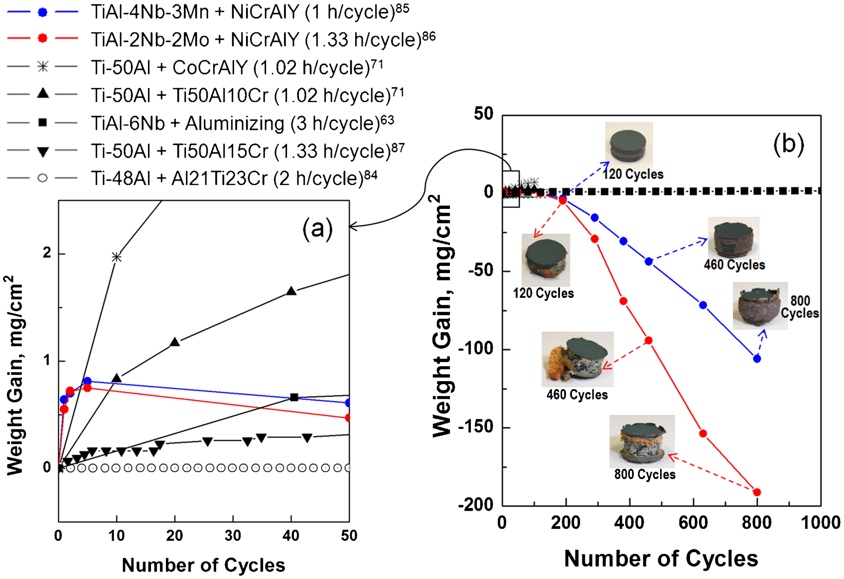
Weight gain curves for the NiCrAlY-coated TiAl–4Nb–3Mn (at.-%) and TiAl–2Nb–2Mo (at.-%) alloys with other published data at 1000°C 86
Oxidation behaviour of γ-TiAl alloy with TBC coating
Thermal barrier coatings have been known to provide surface protection to many components in modern gas turbines. 65 Oxidation resistance of the γ-TiAl alloys/TBC (100–120 μm thick YSZ by APS technique) systems with three different surface modifications (Table 3) was evaluated by isothermal oxidation test at 900°C for 100 h. 14
Three types of surface modification applied before thermal barrier coating (TBC) deposition in Ref. 14
Pre-oxidising in oxygen, or aluminising by PC prevented spallation of the TBC after a 100 h of oxidation tests (Fig. 52). However, the oxidation test for samples without any treatment formed a thick, non-protective Al2O3 and TiO2 mixed oxide layer, and eventually led to failure, as shown in Fig. 53. The aluminising of γ-TiAl without a pre-oxidation treatment produces a less-adherent and mixed (TiO2+Al2O3) oxide layer at the γ-TiAl/TBC interface (Fig. 52a ). In contrast, the aluminising combined with the pre-oxidation treatment in air (Fig. 52b ), or in oxygen (Fig. 52c ), encouraged the formation of a continuous, protective Al2O3 scale. The most beneficial pre-treatment method to improve the oxidation resistance of γ-TiAl was the pre-oxidation in pure oxygen (condition C), followed by TBC application, because it effectively induces the formation of a relatively thin and adherent Al2O3 scale at the γ-TiAl/TBC interface (Fig. 52c ).
SEM cross-section of the thermal barrier coating (TBC)/γ-TiAl alloy systems before (up) and after (down) 100 h of oxidation in air at 900°C a condition A b condition B and c condition C 14
SEM cross-section of the oxide scale formed on the sand-blasted γ-TiAl alloy coated with a zirconia thermal barrier, after 100 h of oxidation in air at 900°C 14
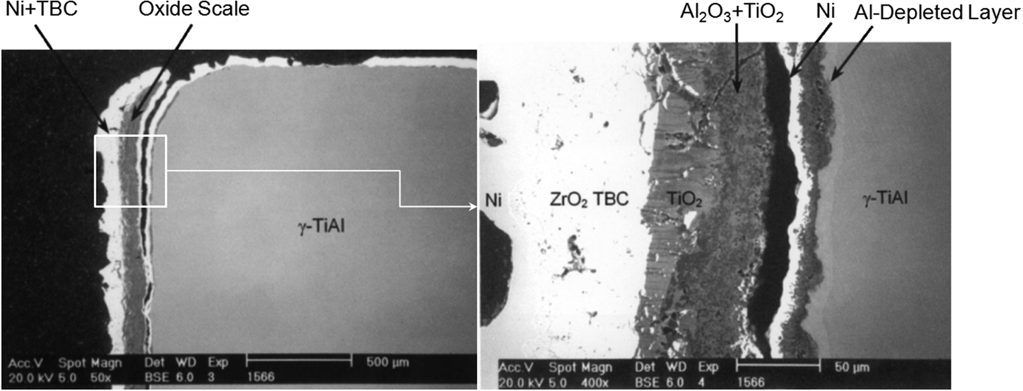
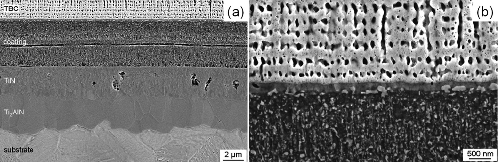
The oxidation behaviour of a Nb-containing γ-TiAl (especially Ti–45Al–8Nb, at.-%) alloy coated with partially yttria stabilised zirconia (PYSZ) TBCs deposited by EB-PVD technique was also examined. 13,74,89,90 Figure 54 shows the effect of the various types of bond coats such as Ti–Al–Cr–Y–N, Ti–Al–Cr and TiAl3 diffusion coating on the oxidation resistance of a Ti–45Al–8Nb (at.-%) topped with EB-PVD TBC. 15 The Ti–45Al–8Nb (at.-%)/TBC (without bond coat) and the Ti–45Al–8Nb (at.-%)/Ti–Al–Cr–Y–N/TBC systems showed rapid oxidation leading to early spallation, while the aluminide bond coatings (in the Ti–45Al–8Nb/Ti3Al/TBC) provided excellent oxidation protection for up to 1000 cycles. The Ti–Al–Cr bond coating also provided reasonable protection to Ti–45Al–8Nb (at.-%) (in Ti–45Al–8Nb/Ti–Al–Cr/TBC).
Mass change of thermal barrier coating (TBC)-coated Ti–45Al–8Nb (at.-%) exposed to air at 900°C 15
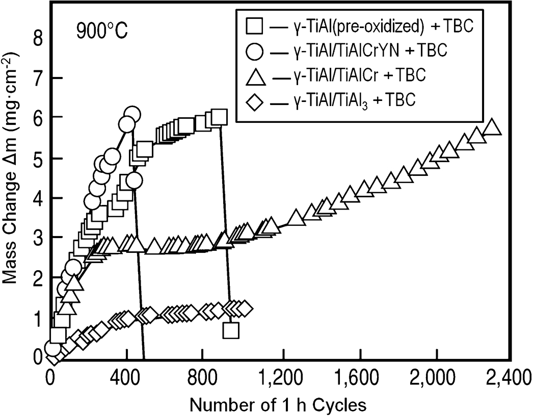
The cyclic oxidation behaviour of TBC-coated Ti–45Al–8Nb (at.-%) samples (Table 4) with and without aluminide coatings as bond coats was also studied under cyclic oxidation tests at 850–950°C. 13 Although no spallation of the TBC occurred for up to 3020 cycles at 850°C, the bare specimen contained cracks in the oxide scale near the scale/substrate at 850°C (Fig. 55) and suffered from spallation at 900°C. The aluminide coating as a bond coat provided effective oxidation protection up to 950°C owing to the formation of a continuous alumina layer between the aluminide coating and the TBC (Fig. 56), whereas the aluminised and annealed specimens exhibited severe spallation of TBC after 520 cycles. The aluminised bond coat consisted of (Nb, Ti) Al3 phase embedded in TiAl2, and the coating gradually transformed into γ-TiAl due to diffusion of Al into the substrate (Fig. 56). In all the cases listed in Table 4, EB-PVD TBCs exhibited very good adhesion to a continuous alumina layer (Fig. 56), and mixed titania and alumina scales (Fig. 55) thermally grown on γ-TiAl. Recently, CrAlN+2 at.-%YN thin films also proved to be a suitable bond coat for EB-PVD TBC on another γ-TiAl based Ti–45Al–8Nb–0·2C (at.-%) alloy. 90 The Ti–45Al–8Nb–0·2C (at.-%)/CrAlN+2 at.-%YN/TBC 90 system provided excellent oxidation protection comparable to the Ti–45Al–8Nb (at.-%)/Ti3Al/TBC 15 system, for up to 1000 1-h cycles at 900°C without spallation (Fig. 57). The zirconia topcoats exhibited excellent adherence to the mixed alumina/chromia scale grown on the degraded coating during thermal exposure.
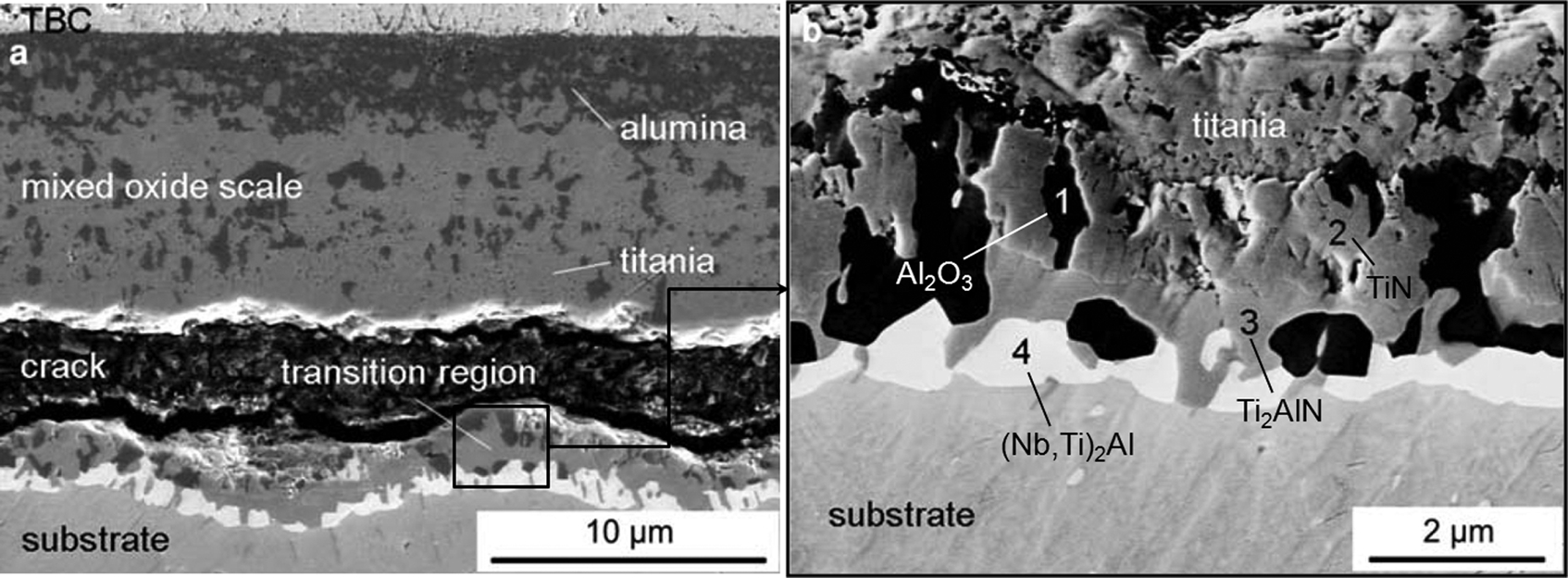
SEM micrograph of thermal barrier coating (TBC)-coated Ti–45Al–8Nb (at.-%) which was exposed to air at 850°C for 3020 cycles, showing a thermally grown oxide (TGO) scale and b transition region between oxide scale and substrate containing different phases 13
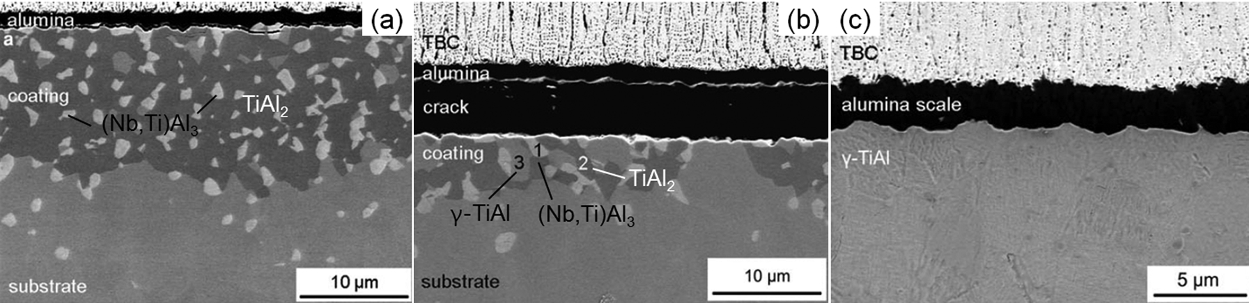
SEM micrograph of thermal barrier coating (TBC)-coated aluminised Ti–45Al–8Nb (at.-%) which was exposed to air a at 850°C for 3020 cycles b at 900°C for 1000 cycles and c at 950°C for 1420 cycles 13
SEM micrographs of a Ti–45Al–8Nb–0·2C (at.-%) coated with CrAlN+2 at.-%YN and thermal barrier coating (TBC) which was exposed to air at 900°C for 1000 cycles, showing a reaction zone between nitride coating and substrate and b TBC/coating interface 90
Thermal barrier coating (TBC) systems on γ-TiAl specimens with and without aluminide coatings 13
Summary
In this review, the oxidation behaviours of uncoated γ-TiAl alloys with and without ternary and quaternary additions were summarised. The inclusion of Nb, W, Si, Mo and Ta appears to improve the high-temperature oxidation resistance of TiAl-based intermetallic alloys with Nb being the most effective alloying element.
In order to further improve the oxidation resistance of TiAl alloy, several intermetallic coatings have been developed and investigated in the past, including aluminising, MCrAlY overlay, and Ti–Al–X coatings. Although reasonable oxidation resistance was achieved, most of these coatings tended to be inherently brittle or formed brittle phases with the substrate material, thus degrading the mechanical properties. Aluminising treatments resulted in the surface formation of TiAl3 and TiAl2 phases, which were found to be brittle and exhibit CTE mismatches with γ-TiAl alloys. MCrAlY is not chemically compatible with TiAl alloys in general, and can form brittle coating/substrate reaction zones due to severe inter-diffusion. Several diffusion barrier layers have been employed to overcome the formation of brittle interlayers and coating premature failure in the MCrAlY/γ-TiAl systems and the effects of diffusion barrier on the oxidation behaviour still need to be investigated. Various compositions of Ti–Al–X coatings such as Ti–51Al–12Cr (at.-%), Ti–50Al–10Cr (at.-%) and Al–21Ti–23Cr (at.-%) were investigated with substrates of Ti–48Al–2Cr–2Nb (at.-%) or Ti–45Al–8Nb (at.-%) or Ti–48Al (at.-%). In the current state, the Ti–Al–Cr–X based coatings have shown better oxidation performance and microstructure compatibility than aluminides or MCrAlY coatings due to the beneficial two-phase microstructure.
Since the discovery of the applicability of TBC to Ti–50Al (at.-%) alloys, the oxidation behaviours of TBC-coated γ-TiAl alloys have been investigated mostly for Ti–45Al–8Nb (at.-%) alloys with bond coat such as Ti–Al–Cr–Y–N, Ti–Al–Cr, and TiAl3 diffusion coatings. Thermal barrier coating was deposited mostly by the EB-PVD technique, and EB-PVD TBCs exhibited very good adhesion to continuous alumina layers and to mixed titania and alumina scales. Investigation of the oxidation behaviour of new TBC/γ-TiAl alloys using other deposition techniques and substrates other than Ti–45Al–8Nb (at.-%) alloys is needed.
The newly developed beta gamma TiAl alloy’s oxidation behaviour was also described. In particular, the two new PM beta gamma alloys TiAl–4Nb–3Mn (at.-%) and TiAl–2Nb–2Mo (at.-%) were found to have moderate oxidation resistance. Their compatibility with NiCrAlY coating was questionable due to the severe inter-diffusion. Further research is needed for the oxidation behaviour of coated beta gamma alloys after applying a diffusion barrier between the beta gamma alloys and coatings.
Although TiAl alloys have great potential as advanced structural materials for gas turbines, their applicability strongly depends on the long-term mechanical properties and compatibility with coatings. Despite the great amount of research carried out worldwide, little attention has been devoted to the fatigue behaviour of TiAl alloy after protective coating deposition. This is a particular area that requires future research.