
Abstract
Mechanical alloying (MA) and mechanical milling (MM) techniques have been widely utilised over the past two decades for synthesis of various alloys and composites with equilibrium or metastable structure at room temperature.
One of the most interesting features of MA/MM is the ability to produce nanocrystalline and amorphous materials. Several mechanisms for formation of nanocrystalline and amorphous structures have been introduced based on experimental findings and similarity of MA/MM to other solid-state processing routes. In this paper, the recent experimental observations reported on development of nanocrystalline and amorphous structures using ball mill technique are selectively examined and critically reviewed to provide further insight into the key issues related to this solid-state technique. The review includes four major parts. It begins with a brief introduction to MA/MM and the principles of ball milling process for synthesis of materials. The second part is devoted to the formation of nanocrystalline structure by ball milling process. The earlier studies are summarised with special emphasis on the minimum grain size obtainable by ball milling, besides the recent progresses on the prediction of minimum grain size based on dislocation models are analysed and discussed in detail. The third part deals with the amorphisation reaction induced by ball milling. This section includes the thermodynamic and kinetic aspects, the criteria developed for amorphisation reaction and microstructural evolution of powders during MA leading to the amorphisation reaction. The last part is devoted to the bulk amorphous/nanocrystalline alloys produced from precursor powder.
Principles of mechanical alloying/milling process
Studies of processing techniques that lead to the far-from equilibrium structures are important for development of novel materials. Some of these processing techniques include rapid solidification, mechanical alloying (MA) and mechanical milling (MM), plasma processing, spray forming, laser processing, physical and chemical vapour deposition techniques and ion mixing. It is through these processes that the range of obtainable microstructures is drastically increased and the improvements in properties are achieved.
Mechanical alloying and mechanical milling are synthesis processing of materials involving continued ball milling of powders. The severe plastic deformation, repeated flattening, cold welding and fracturing of powder particles during MA/MM lead to the significant refinement of microstructure, which is often accompanied with transformation to metastable structures. The final powder produced by MA/MM can be subsequently either consolidated by standard powder metallurgy techniques into bulk materials with desirable properties or deposited on surfaces of engineering parts using various thermal spraying methods. There are lots of papers published on synthesis and processing of various materials by MA/MM during the past decade showing improved microstructures and properties.
The researches have shown that MA can provide microstructures which are impossible or difficult to obtain with other techniques. It can overcome fabrication difficulties in achieving high solid solubility, mixing of elements with a high vapour pressure and/or large difference in melting points. Mechanical alloying provides the advantage of eliminating the need for liquid (or gaseous) phase and high temperature processing. Additionally, it does not require miscibility of the constituents in the liquid state. Thereby, MA offers a greater flexibility in the choice of constituent materials.
Figure 1 presents some of the major applications and attributes of MA and MM in the field of materials processing. A comprehensive list of materials synthesised by MA/MM and further information on the application of ball milling process can be found in the reviews by Koch, 1 Calka 2 and more recently by Sherif El-Eskandarany 3 and Suryanarayana. 4
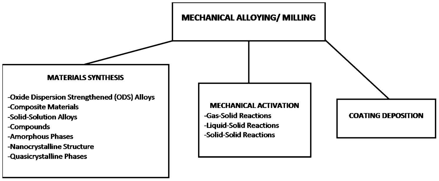
Applications of mechanical alloying (MA)/mechanical milling (MM) to fabrications of various engineering materials
From the viewpoint of mass transfer, the ball milling processes can be divided into two major categories:
Milling processes that involve mass transfer between the components. Such cases can occur during ball milling of multi-component powders (e.g. a mixture of elemental or dissimilar alloy powders) and are associated with compositional changes of powder particles. This category is known as MA.
Milling processes that involve no mass transfer and convert a single-component powder (e.g. elements or intermetallic compounds). These cases have often been termed as MM or mechanical grinding (MG).
During the milling process, powder particles are trapped between colliding balls and undergo severe plastic deformation. Ball-powder-ball collisions lead to the following events:
Repeated cold welding and fracturing of particles. In case of MA, this process results in the mixing of constituents and formation of composites of powders. Changes in particles morphology and microstructure during ball milling of ductile metal powders are produced by simultaneous process of cold welding and fracturing. During the early stages of ball milling, cold welding of powder particles dominates leading to a continuous increase in particle size. After a period of milling, particles deform to the extent that cracks initiate, propagate and ultimately fracture the particles as work hardening limits ductility and further cold welding. This is followed by a third stage; steady-state stage in which there is a balance between the frequencies of cold welding and fracturing processes so that the average particle size remains unchanged. The extent of these two events is determined by mechanical properties of the elemental powders, such as elastic modulus, ductility, yield stress, hardness and work hardening rate as well as the magnitude of the impact provided by colliding balls. When all raw material powders are ductile, MA leads to the development of an alternate layered composite, with a progressively refined layer thickness with increasing milling time. A typical layered structure consisting of cold welded Ni and Nb layers is illustrated in Figs. 2 and 3. For ductile–brittle systems, MA causes an ultrafine particulate composite structure with uniform distribution of brittle phase in ductile matrix. The presence of hard particles can facilitate the fracturing process. Thereby, the time required to attain steady-state condition may reduce. In contrast, when all constituents are brittle only a homogeneous mixture of initial powders is formed during MA. Such a fine microstructure provides extensive interfaces between layers which is suitable for any potential reaction between constituents at longer milling times or during subsequent processing (e.g. hot press, hot extrusion, thermal spray).
Creation of high density of lattice defects (point defects, dislocations, stacking faults, etc.) induced by severe plastic deformation. It has been shown that a dense dislocation network (ρ≈1017 m−2) forms even in nominally brittle intermetallics like Nb3Sn under ball milling conditions. 5
Material transfer by diffusion of components. Diffusion during MA is significantly accelerated by lattice defects and by a momentary increase in temperature of particles trapped between colliding balls. Modelling as well as inferences drawn from the product structure suggest a temperature rising to ∼373–473 K range, resulting from the kinetic energy of the milling balls. However, if a large exothermic reaction is involved, much higher local temperatures can be produced by milling. 6 In a static system, the rate of solid-state reactions is often controlled by diffusion of atoms across the product phase which is developed along the interfaces. Consequently, the reaction rate is significantly reduced with time because the growing intervening product layer hinders further interdiffusion of atoms across the interfaces by acting as a diffusion barrier. In contrast, in dynamic processing techniques, like MA, the fresh interfaces between constituents/reactants are continuously created by repeated deformation, fracture, and cold welding of powder particles during collision of the grinding media. As a result, the product interlayer phase is fragmented and dispersed in the matrix. Thus, they cannot affect the kinetics of solid-state reaction unless a high fraction of product is formed.
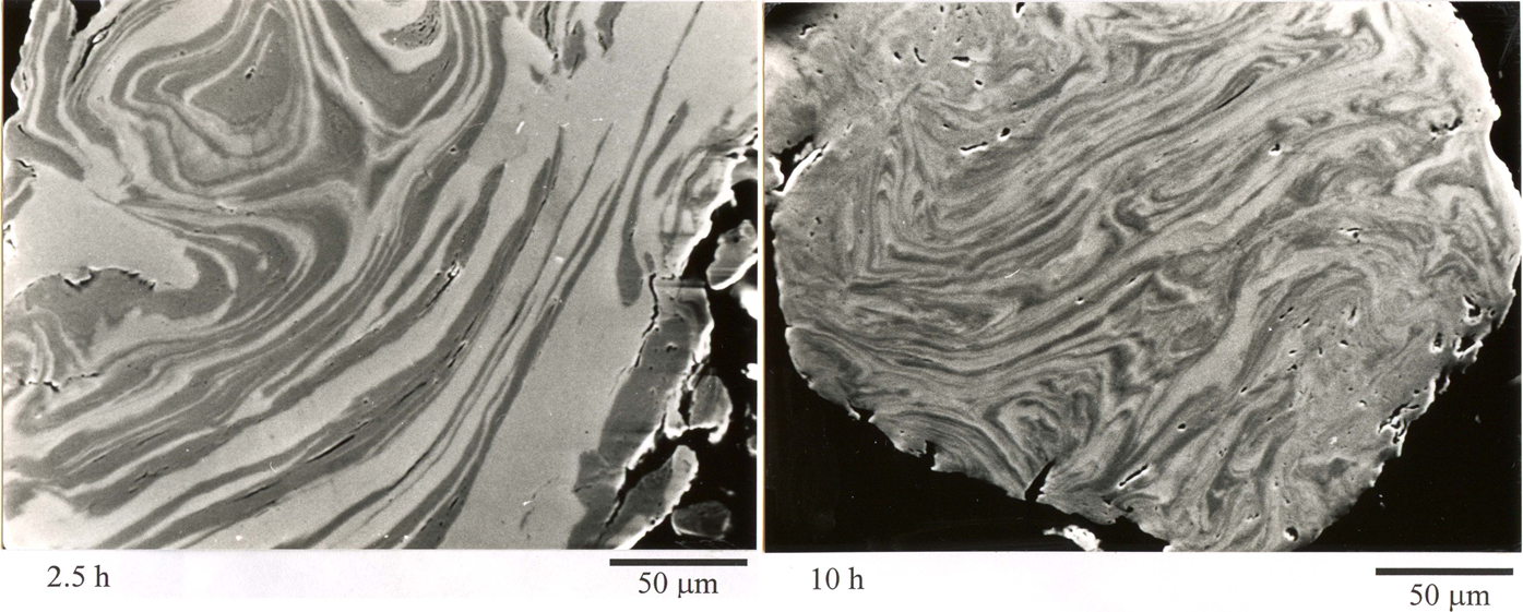
Formation of an alternate layered microstructure during mechanical alloying (MA) of Ni–Nb powders for 2·5 and 5 h 7
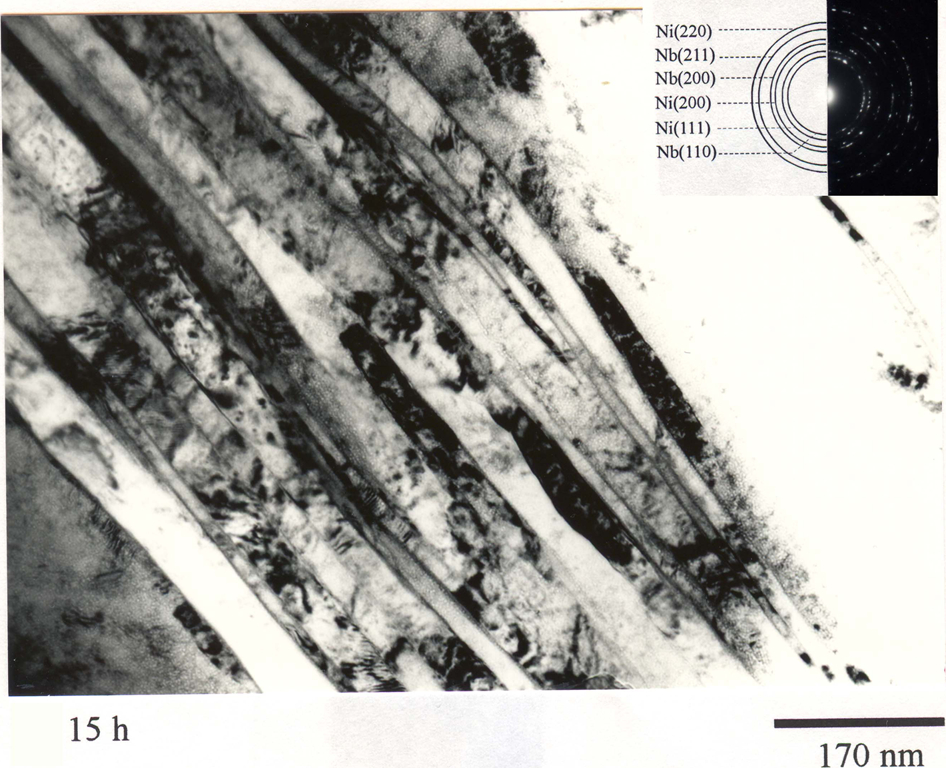
Transmission electron microscopy (TEM) image from the edge of Ni60Nb40 powder particles showing the nano-sized layered microstructure developed during mechanical alloying (MA) of Ni60Nb40 powder for 15 h 7
It has been shown that in MA/MM experiments not only the milling time but also further parameters may have significant influence on the above mentioned phenomena. These parameters include the type of the mill, 8,9 the milling tools material, 10–12 the intensity of milling, 13–16,214–216 the ball-to-powder weight ratio, 14–19 the milling temperature 20–22 and the milling atmosphere. 20,23–25 All these parameters influence the resolved forces at the point of contact between ball and powder under a given ambience (temperature, atmosphere) and material properties. 26 Variation of these parameters can lead to differences regarding the sequence and time required for transformation and the final phase (or phases). Hence, by controlling these parameters a large variety of materials ranging from stable to metastable structures can be synthesised by MA/MM.
Development of nanocrystalline structure
Nanocrystalline materials are generally known as those materials that have a crystallite size less than 100 nm. This upper limit of 100 nm is based on the fact that most properties (mechanical/physical/chemical) of materials start to change significantly at this point. Although there are lots of experimental results showing that the change in properties can occur in crystallite size much smaller or in some cases larger than 100 nm. For example in case of nanocrystalline Fe, the deviation of elastic moduli from the coarse grain value occurs only at a very small grain size, well below 7 nm. 27 Similar results have been found by other researchers 28 and also supported by computer simulation. 27 On the other hand, plastic behaviour (e.g. yield strength, superplasticity) of materials is much more sensitive to the grain size and can vastly change near or even well above 100 nm, as is the case for ultrafine grained materials (UFGM). 29
In nanocrystalline materials there is a significant fraction of atoms in the grain boundaries compared to inside the grains. In conventional polycrystals that have a grain size of 10 μm, the volume fraction of atoms located in grain boundaries is about 10−4. If the grain size is reduced to 10 nm or less, the density of the grain boundaries increases to 1018–1021 cm−3. This means that about fifty per cent of the atoms are located in grain boundaries. 30 Therefore, the properties of this group of materials are greatly influenced by the structure and properties of the grain boundaries.
It is anticipated that nanocrystallinity could lead to a change of physical and mechanical properties. By decreasing the grain size, it is possible to enhance both hardness and strength. The high volume fraction of grain boundaries increases the diffusion rate and solid solubilities. It also permits sintering of compacted powders at much lower temperature. Nanocrystalline materials have been shown to have higher electrical resistivity, superior soft magnetic properties, higher chemical activity and higher thermal expansion coefficients in comparison with the corresponding coarse-grained materials. Another interesting feature associated with development of nanocrystalline structure in alloys or pure elements is polymorphic/allotropic phase transition below a critical grain size at room temperature. The allotropic transition in pure elements has been reported for Ti (HCP→FCC), 31,32 Nb (BCC→FCC), 33 Zr (HCP→FCC) 34 and Hf (HCP→FCC). 35 This phenomenon was claimed to be caused by structural instability as a consequence of negative hydrostatic pressure (from crystal-core to surface) and/or high strain rate deformation in MA/MM. 31–34 In contrast Seelam et al. 36 reported that the hcp→fcc phase transformation in mechanically milled Group IVB elements are, at least partially, due to pick-up of interstitial impurities by the powder during milling of these powders to the nanocrystalline state. These characteristics along with the possibility to obtain different properties by controlling grain size have made nanocrystalline materials very attractive for potential engineering applications. Reviews of properties of nanocrystalline materials can be found in Lu, 37 Suryanarayana, 38 Suryanarayana and Koch, 39 Kumar et al., 40 and Meyers et al. 41
Vapour deposition, plasma processing, gas-condensation, chemical precipitation and crystallisation from the amorphous phase are well established processing routes for obtaining nanocrystalline materials. However, it is well known that MA and MM as solid synthesis routes can also be applied for production of a nanocrystalline structure. Comparison of different preparation methods in terms of cost and productivity demonstrates that MA/MM is the most cost effective route capable of producing nanocrystalline materials in large quantity. Nanocrystalline structures have been developed in single-component powders, in compounds and in multi-component powders. Peak broadening in X-ray diffraction and in some cases transmission electron microscopy (TEM) were used to study the grain refinement and evolution of nanocrystalline structures. It is worth mentioning that powder particles prepared by MA/MM are rarely monocrystals. Instead, MA/MM powders have micrometre dimensions with interior nanometre microstructure. The structure of each particle can be described as a poly-nanocrystalline.
Full explanations of several phenomena associated with formation of nanocrystalline structure are still lacking, but the following information has been reported.
Development of nanocrystalline structure
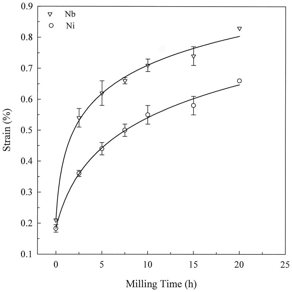
Grain refinement of powders to the nanometre size is governed by the plastic deformation induced during milling. In general, the grain size decreases continuously with milling time until a minimum (saturation) size is approached. 7,42–45 A typical variation of grain size with milling time is presented in Fig. 4.
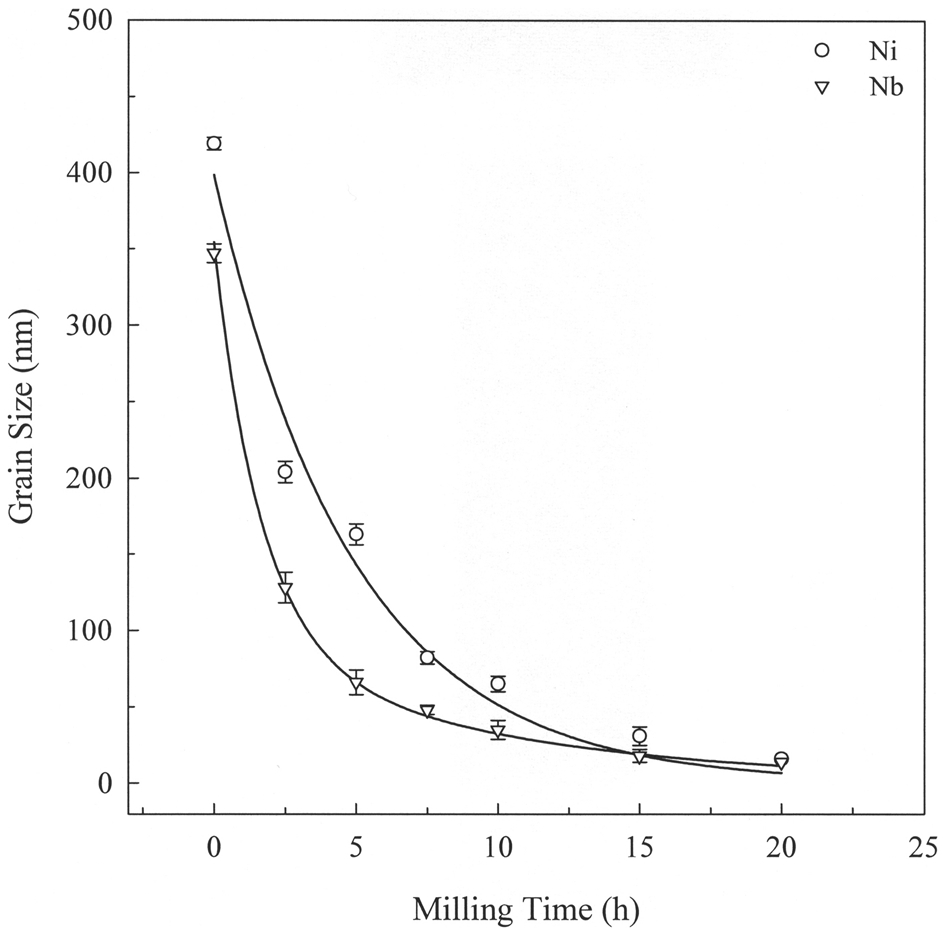
Variation of Ni and Nb grain sizes as a function of milling time 7
Further refinement seems to be difficult to achieve for a fixed set of experimental conditions. Transmission electron microscopy observations have revealed that at the early stages of milling, a very fine microstructure is obtained which contains some shear bands and many dislocations. 42,43 The latter are converted into a dislocation cell structure which subsequently creates low-angle grain boundaries. With prolonged processing and absorption of more dislocations into the boundaries, this structure is transformed to a fully nanocrystalline structure with completely random orientation of neighbouring grains which are separated by high-angle grain boundaries. 43,46 The grain refinement process during ball milling is schematically illustrated in Fig. 5.
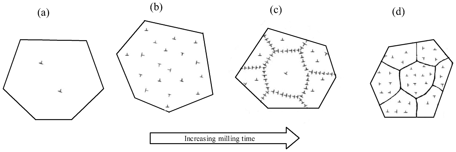
Schematic representation of development of nanocrystalline structure in a single grain during ball milling: a original grain with a low dislocation density, b a high dislocation density created by severe plastic deformation of grain, c dislocation alignment and formation of low-angle grain boundaries and d transformation to high-angle (true) grain boundaries
Minimum grain size
Experimental findings have revealed that the minimum grain size for a given material is a constant value independent of milling conditions. In fact, the minimum grain size is determined by intrinsic properties of materials such as melting temperature, crystal structure and deformation behaviour. The milling conditions can only affect the rate at which the grains refine and approach the minimum size. Eckert et al.
43
observed that the minimum grain size d
min in a series of FCC metals including Al, Cu, Ni, Pd, Rh and Ir scales inversely with the melting point T
m or the bulk modulus B of the respective metals. As shown in Fig. 6, the higher the T
m or B, the smaller the d
min is obtained. Eckert et al.
43
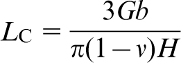
have also shown that for pure FCC metals there is a linear relationship between the minimum grain size d
min and the critical equilibrium distance between two edge dislocations L
c in a pileup. L
c is given by equation (1)
47
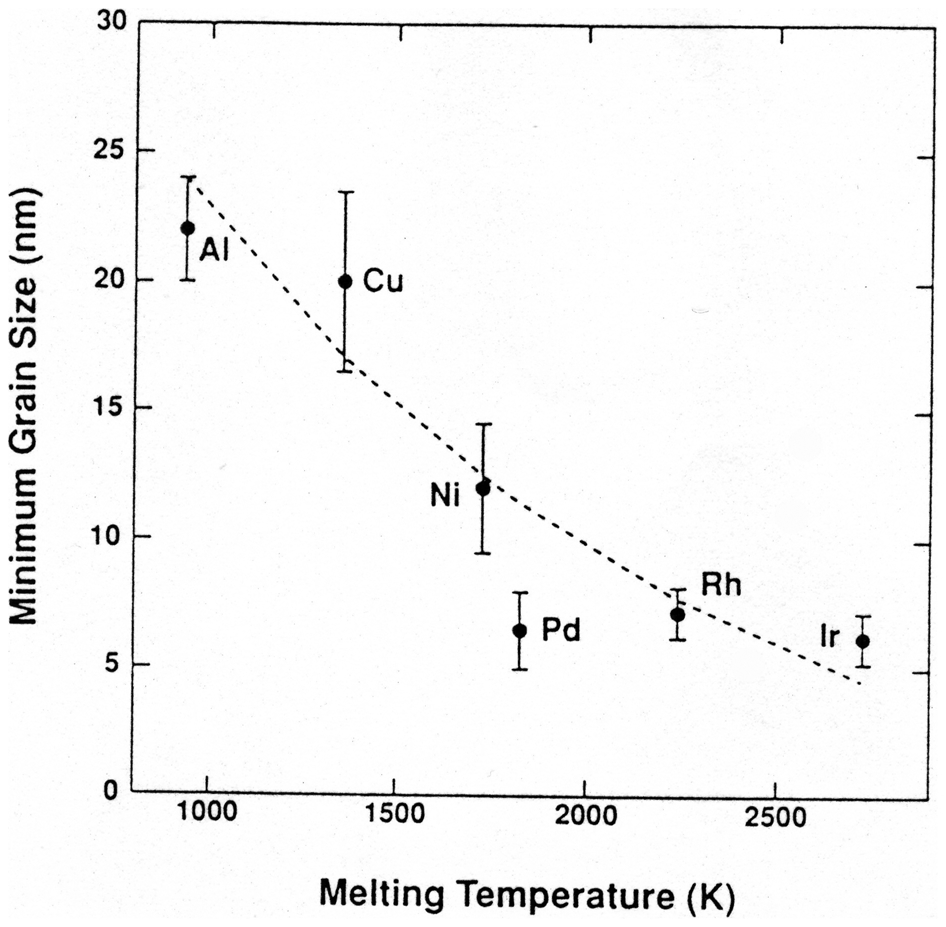
Minimum grain size obtained by ball milling for several FCC metals versus melting temperature 43
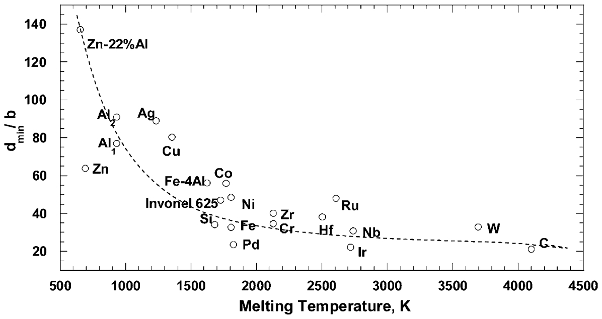
However, no clear inverse correlation between the minimum grain size and melting temperature was obtained for BCC metals Cr, Fe, Nb, W as well as for HCP metals Hf, Zr, Co, Ru. As shown in Fig. 7, the minimum grain size of these series of BCC and HCP metals suggested a constant size (9 and 13 nm respectively) independent of melting temperature. Koch 1 observed that only the lower melting temperature FCC metals (≤T m for Pd) exhibit an inverse dependence of d min on T m.
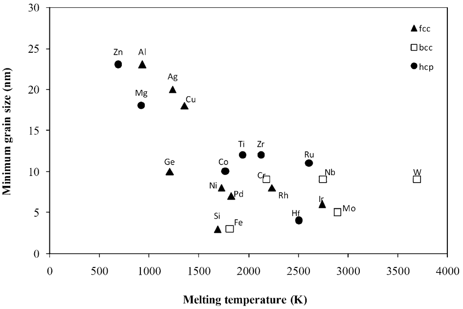
Minimum grain size of ball milled FCC, BCC and HCP metals versus melting temperature
The dependence of minimum grain size versus melting temperature has been discussed with respect to the competing rates of creating dislocations due to work hardening and recovery phenomena which scale with the melting point. 43,48 Thereby, the minimum grain size achieved by ball milling is determined by the balance between creation and annihilation of dislocations during processing. This correlation explains why the minimum grain size for Al (T m = 933 K) is about 22 nm while it can be reduced to 7 nm for Pd (T m = 1825 K) as seen in Fig. 6.
Mohamed et al.
49–51
analysed the minimum grain size that was obtained by ball milling by plotting the normalised minimum grain size d
min/
Normalised minimum grain size (d
min/
The normalisation of the grain size by dividing it by the Burgers vector 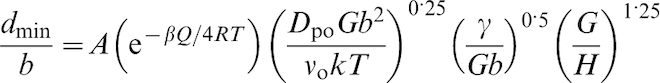
Normalised minimum grain size d
min
/
It is worth noting that the data for Ag, Cu, Co, and Zn–22% Al with stacking fault energies γ of <60 mJ m−2 was fitted with a separate straight line. 52 Since the metals with lower stacking fault energy present larger separation of two partial dislocations, it is quite possible that, due to the severe deformation and high internal stresses developed during milling, the separation between the two partial dislocations may significantly decrease, leading to an ‘effective’ stacking fault energy, which is much higher than that obtained in the absence of external forces. 52
As mentioned earlier, the dependence of minimum grain size d min and melting temperature (Fig. 9) can be understood by the fact that the self-diffusion activation energy Q scales with melting temperature T m.
Eckert et al.
43
and Mohamed
50
observed that the minimum grain size d
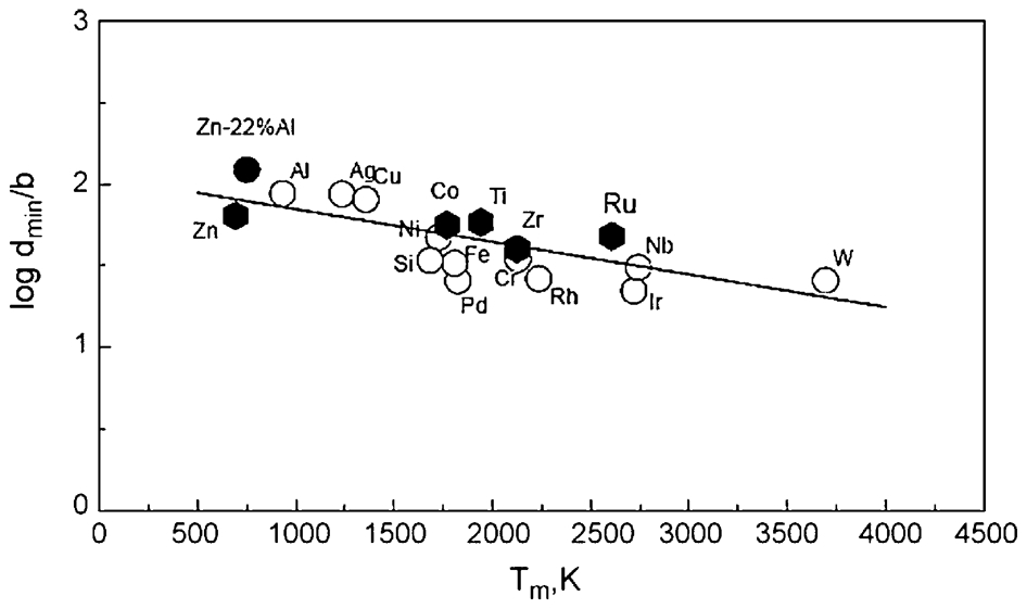
min for FCC and BCC metals scales with the bulk modulus B. In order to examine whether the behaviour of HCP metals is consistent with the above trend, Mohamed
52
plotted the available Q value of all metals against B
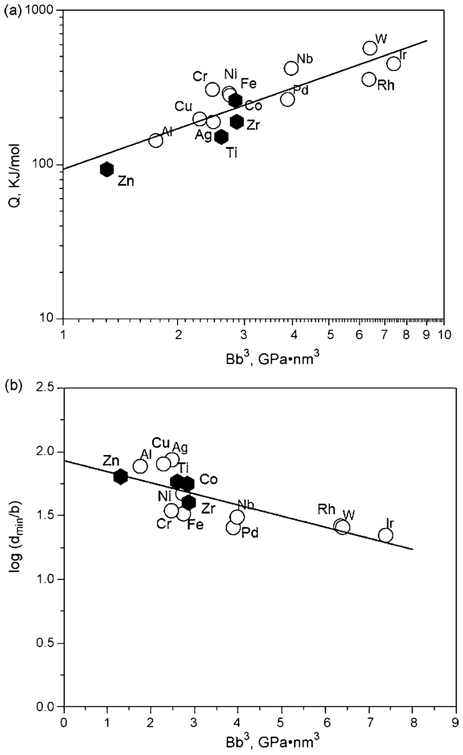
a The activation energy for the self-diffusion Q versus the bulk modulus multiplied by the cube of the Burgers vector B b 3. b The logarithm of the normalised minimum grain size d min / b obtained by milling versus the bulk modulus multiplied by the cube of the Burgers vector B b 3. HCP metals are represented by solid hexagon 52
Koch has argued that a different grain size can be obtained by altering the rate of work hardening (e.g. by changing the ball-to-powder weight ratio or the type of mill) and/or rate of dislocation recovery (e.g. by changing milling temperature). 53 Hence, the grain size in final material can be controlled by changing the equilibrium rate of dislocation creation and recovery.
Experiments show that lowering milling temperature leads to a finer grain size. 54 This behaviour is also predicted by the dislocation model of Mohamed. Furthermore, it should be noted that the magnitude of the decrease in d min with decreasing milling temperature is predicted to be significant when the activation energy for recovery is high. In this case, the rate of recovery is very low and the minimum grain size is essentially governed by the rate of hardening. For example, the model predicts that: (a) when the milling temperature is decreased from 300 to 90 K, d min in Al does not decrease appreciably, and (b) the amount of decrease assumes significance in the following order: Al, Cu, Ni, and Ir. These predictions are in agreement with experimental trends. First, Zhou et al. 55 reported that d min in Al is not very sensitive to milling temperature; the difference between d min produced at 300 K and that produced at 90 K is within the range of experimental error. Second, when milling temperature was changed from 303 to 188 K, d min in Cu decreased from 26 to 17 nm. 54
The dependence of d min on milling temperature has directed researchers to another version of ball milling process known as ‘cryomilling’. This process benefits from ball milling at cryogenic temperatures. Two different methods have been applied for cryomilling. In most cases, a cryogenic liquid (e.g. liquid N2) flows continuously inside the mill vessel. The raw materials are ball milled with the cryogenic liquid forming a slurry. In some set-ups the cryogenic temperature during ball milling has been achieved by circulation of cryogenic liquid around the outside surfaces of milling vessel. Basically, cryomilling experiments can be carried out in any type of milling apparatus although the attrition ball mill is often preferred. This type of mill comprises of a static cylindrical vessel with a rotating impeller with which a rather large quantity of powders (several kilograms) can be processed making it potentially suitable for commercial exploitation. The cryogenic liquid can be readily flowed inside/outside of milling vessel.
The grain refinement mechanism during cryomilling was found to be similar to that observed during conventional room-temperature ball milling. 56 With increasing interior strain, the dislocation density increases gradually. At a certain strain level, these dislocations will form sub-boundaries by aligning, annihilating, and recombining with each other. Upon further deformation, the low-angle sub-boundaries are changed to high-angle boundaries (true boundaries) by the absorption of more dislocations into the boundaries or accompanying grain rotation. Eventually, the initial large grains decompose into small grains separated by true boundaries. Finally, the grain size reaches a given constant size. Once this size is reached, further refinement ceases.
Cryomilling process includes several advantages over room temperature ball milling. A benefit of cryomilling is that the rate of diffusional process like annihilation of dislocation is extremely limited at cryogenic temperature. As discussed earlier, under this condition the grain refines with a much higher rate. Hence the milling time required to attain a certain grain size is significantly reduced. Shorter milling time in case of cryomilling implies that a large quantity of powder can be processed in large-scale low-energy ball mills within a reasonable milling time. It appears that the cryomilling does not significantly affect the minimum grain size. The experimental results show that the minimum Al grain size obtainable by ball milling falls in the range of 20–26 nm. 43,57 These values were obtained by processing of Al powders in high-energy ball mills such as SPEX8000 as well as in low-energy ball mills. Consistently, cryomilling of Al powder resulted in a nanocrystalline structure with an average grain size of about 26 nm. 58,59
For those cryomilling processes in which the powders are mixed with liquid N2, the reaction of constituents with N2 must be considered. This reaction seems to proceed to a great extent during ball milling as plastic deformation; flattening and fracturing of powder particles repeatedly produce fresh, clean and highly reactive surfaces. The powder-N2 reaction can be more serious in case of reactive elements such as Al and Ti. However, experimental results do not support this prediction. For example, during cryomilling of 5083 Al powder the nitrogen picked up was found to be 0·16 wt-%. 59,60 Nitrogen dissolved interstitially in Al lattice forming a supersaturated solid solution. It should be noted that because of low temperature, formation of nitrogen-containing dispersoids such as AlN are kinetically improbable, although there is a large driving force for the formation of such compounds (e.g. ΔG AlN = −287·1 kJ mol−1). However, subsequent heating during differential scanning calorimetry (DSC) run or upon powder consolidation of cryomilled 5083 Al led to the formation of various secondary phases including AlN and Al2O3. The presence of these precipitates was confirmed by atom probe field-ion microscopy (FIM) and high-resolution transmission electron microscopy (HRTEM) observations but the volume fraction of precipitates were not determined. Furthermore, the XRD patterns of cryomilled powder after heat treatment showed no traces of secondary phases suggesting that the amount of the dispersoids are virtually very small <1 vol.-%. 58 It is worth noting that the dispersion particles formed during cryomilling acquired nanoscale size ranging from 1 to 30 nm, with majority of 3–10 nm. The average spacing between the dispersoids was measured to be less than 10 nm. In another study, it was found that cryomilled pure Al contains fine particles of aluminiumoxynitride with a diameter of 2–10 nm and spacing of 50–100 nm. 61 Later, it was observed on HRTEM that in this material the dispersoids are 10–15 nm in two dimensions but their thickness is only a few atomic layers. 62 These dispersions were found to be incoherent in nature, highly stable at high temperature and insoluble in matrix. 63 As will be discussed later in the ‘Bulk nanocrystalline/amorphous alloys prepared by consolidation of mechanical alloying/mechanical milling powders’ section, the presence of these finely dispersed particles can play a critical role in retarding grain growth in the nanocrystalline materials through the so-called Zener mechanism even though their volume fraction is low. Furthermore, they could effectively obstruct dislocation motion and therefore reduce the minimum grain size.
It has been shown that the minimum grain size is also affected by the alloy composition. For example, Eckert et al. 43 demonstrated the influence of composition on the minimum grain size in Fe–Cu nanocrystalline alloys. Also, Rafiei et al. 64 performed MA of Fe–Al–Ti ternary system to study the effect of Ti addition on alloying and formation of nanocrystalline structure in Fe–Al system. It was found that (Fe,Ti)3Al intermetallic compound achieves a smaller crystallite size compared with Fe3Al phase. Xun et al. 56 studied the development of nanocrystalline structure in Zn–22 wt-% Al using cryomilling. They reported that the final structure after 16 h of ball milling consisted of two phases: Al(Zn) and Zn(Al) solid solutions. The minimum grain size d min was measured to be 33 nm for the Al(Zn) and 41 nm for Zn(Al) phases. The d min of Zn(Al) phase is much larger than that reported for pure Zn (17 nm). In contrast, the d min of Al(Zn) phase is higher than that of pure Al (26 nm). The presence of alloying elements can significantly affect the rate of lattice defects generation, dislocations mobility and the rate of defects annihilation during ball milling process by changing the value of several parameters such as work hardening rate, stacking fault energy, melting temperature and diffusivity. Besides, the intrinsic properties such as melting temperature and crystal structure, the history of the as-received material and the level of contamination introduced during the deformation process (e.g. oxygen and nitrogen) can also affect the accumulation and annihilation of dislocations by, for example, blocking the dislocations slip by grain boundaries (pile-up) or pinning of dislocations by foreign atoms. Owing to these complexities and since the relative effect of each factor is not well-understood, especially for ball milling process in which an intensive plastic deformation at high strain rate is involved, the rate of grain size reduction in metals and alloys cannot be easily explained and compared with each other in terms of their physical, crystallograpical and mechanical characteristics.
Finally, the finely dispersed particles, second phase precipitates and solute segregation can lock dislocations as well as grain boundaries, reducing the minimum grain size. 53 For instance, Chung et al. 65 found that cryomilled pure Ni attained a grain size of 132 nm after milling for 8 h. Addition of 0·5 and 2·0 wt-% AlN powder with an initial particle size of 2 μm reduced the Ni grain size down to 65 and 37 nm, respectively. In this case, AlN particles drastically decreased in size during cryomilling leading to a nanoscale size of 20–300 nm. It is worth noting that if the initial microscaled reinforcements do not fracture to nanoscaled particles during milling process, they have no significant effect on the grain refinement of the matrix. 66,67
Enhancement of lattice strain
Owing to the generation of lattice defects, especially dislocations, the grain refinement to nanoscale size during MA/MM is accompanied with an increase in internal strain. The internal strain eventually approaches a saturated value (Fig. 11). In some cases like MM of AlRu, 42 however, the internal strain reached first a maximum and decreased subsequently at longer milling times when dislocations were consumed by increasing the number of grain boundaries. Like the minimum grain, it has been observed that the amount of internal strain is influenced by such factors as composition, melting temperature, crystal structure and strain rate (low/high intensity milling). 43,53
Enhancement of internal strain in Ni and Nb during mechanical alloying of Ni60Nb40 powder 7
Amorphisation
Amorphous metallic alloys have unique and useful properties which are not found when the alloy is in the crystalline state. To some extent, the properties of amorphous materials are influenced mainly by lack of long-range periodicity in amorphous state as well as free volume density and distribution. Amorphous materials exhibit high strength and hardness, low magnetic losses, high corrosion resistance, low degradation of mechanical properties in irradiation environments and improved catalytic properties. 68–70 This combination of physical and mechanical properties in amorphous materials has led to commercial applications especially in the field of magnetic materials. General reviews of properties and applications of amorphous alloys can be found in the study of Cahn, 71 Kimura and Masumoto, 72 Inoue and Hashimoto, 73 and Suryanarayana and Inoue. 74
Several methods have been introduced for obtaining amorphous structures. These methods can be categorised in three major groups:
Amorphisation from the vapour state in which the vapour of materials obtained by physical (e.g. electron beam, plasma sputtering) or chemical techniques is quenched onto a cold substrate. This is a process that gives an extremely high effective quench rate, of the order of 1013 K s−1, since deposition occurs atom by atom and the heat of condensation is rapidly removed through the thin film.
Amorphisation from the liquid state in which a melt is quenched in contact with a cool and efficient heat sink. Thereby, any nucleation and growth of crystalline phases is kinetically bypassed and a frozen liquid configuration is yielded. The formation of the first metallic glass of Au75Si25 was reported by Duwez at Caltech, USA, in 1960 75 by rapid quenching of liquid at very high rates of 105–106 K s−1. This metallic glass was in the thickness of a few micrometres. During the last two decades, several families of metal alloys that exhibit outstanding resistance to crystallisation in the undercooled liquid state have been developed. Upon cooling, these alloys readily form glass or vitrify to form bulk amorphous alloys or bulk metallic glasses (BMGs) with the thickness range of millimetres to centimetres at a very low cooling rate of the order 0·01 K s−1. Three key empirical criteria have been adopted for development of BMG:
Multi-component alloys of three or more elements,
Atomic radius mismatch between main elements for at least 12%,
Negative heat of mixing between the main elements.
Typical bulk glassy alloy systems along with critical diameter, preparation methods and application examples of bulk glassy alloys can be found in a number of reviews. 76–85
Several parameters have been introduced for prediction of glass-forming ability (GFA) of metallic alloys. Most of them consider only the thermal features of amorphous alloys such as: T rg = T g/T l, 86 ΔT x = (T x−T g), 87 α = T x/T l, 88 β = T x T g/(T l−T x)2, 89 γ = T x/(T l+T g), 90 δ = T x/(T l−T g) 91 and, γc = (3T x–2T g)/T l 92 where T g, T x and T l are glass transition, onset of crystallisation and liquidus temperatures, respectively. A critical analysis of the existing data in terms of the different glass-forming criteria was conducted by Suryanarayana et al. 93 They concluded that none of these criteria are reliable as a general parameter in prediction of GFA of different alloys.
Amorphisation from the solid state, such as irradiation with energetic particles (neutron, ions, etc.), thermal interdiffusion between two elements in a system of alternate layers (diffusion-induced amorphisation), dissolution of hydrogen gas and ball milling, i.e. MA and MM.
The crystalline-to-amorphous phase transformation induced by ball milling was first reported by Yermakov et al. 94 for MM of Co–Y system and by Koch et al. 95 for MA of Ni–Nb system. Since then, there has been a growing interest in this solid-state route and a wide variety of binary and ternary systems have been processed. The details for various systems are given in the reviews of Weeber and Bakker, 96 Gaffet et al. 97 and Suryanarayana. 4,98
A large number of alloy systems in a wide composition range have been successfully amorphised by MA/MM; as well, and the effects of milling variables such as mill energy, milling temperature and atmosphere on amorphisation ability have been studied. The understanding of the amorphisation reaction during ball milling has been the subject of many investigations, nevertheless there is still some uncertainty regarding amorphisation mechanisms.
Amorphisation by MA
Amorphisation by MA has been suggested to be the same as that of solid-state amorphisation in alternate layered structures, where the amorphisation reaction is governed by interdiffusion of constituents during annealing. The application of this mechanism to MA is based on the observation that a similar layered structure, although the layers are not perfectly planar and uniform, develops during MA in which a solid-state amorphisation reaction could occur.
Thermodynamic and kinetic aspects
Johnson, 99,100 Schultz 101 and Bakker et al. 102 have reviewed the thermodynamics and kinetics of different solid-state amorphisation methods.
Based on experimental evidence, Johnson 99 proposed the following two criteria for the solid-state amorphisation reaction by annealing of an alternate layered structure:
A negative heat of mixing in the amorphous state which provides a low enough free energy of amorphous phase necessary to attain the thermodynamic driving force for a crystal-to-amorphous reaction.
An anomalously fast diffusion of one element into the host matrix of the other and into the amorphous phase to be formed at a temperature below the crystallisation temperature, which favours the formation of the amorphous phase with respect to the competing crystalline equilibrium phase.
A fine multilayered structure, providing an extensive interface area, is needed for this kind of interdiffusion reaction. Furthermore, it has been suggested that the formation of the amorphous phase requires suitable nucleation sites (e.g. grain boundaries). This possibility is supported by the experiments of Vredenberg et al. 103 and Meng et al., 104 which showed the lack of amorphisation reaction at Ni/Zr interface in the absence of high-angle Zr grain boundaries.
Solid-state amorphisation by annealing has been observed in a large number of elemental pairs such as Ni–Zr, Cu–Zr, Fe–Zr, Cu–Ti, Ni–Ti, Co–Zr as reviewed by Suryanarayana and Inoue 74 and Johnson. 99 All investigated pairs exhibit a large negative heat of mixing and a large atomic size mismatch. The large difference in diffusivity of the two species has been experimentally confirmed in some cases including Fe–Zr, Co–Zr and Ni–Zr systems where Fe, Co and Ni diffuse several powers of ten faster than Zr (for more detail see Cahn 105 and Greer et al. 106 ). For the detailed experimental observations and interpretation for solid-state amorphisation in the binary metal systems, the readers are referred to the review articles. 98–104
Mechanical alloying leads to the development of an ultrafine composite of constituents in which a solid-state amorphisation reaction can occur. It is therefore reasonable to extend the model for solid-state amorphisation by annealing to amorphisation by MA. However, MA additionally involves a high density of lattice defects such as vacancies, interstitials, dislocations and grain boundaries which can influence both the thermodynamics and the kinetics of the amorphisation reaction by MA. They raise the free energy of the crystalline system and thus destabilise it with respect to the amorphous state. At extremely small crystallite or particle size, specific surface area and hence interfacial Gibbs energy component of overall Gibbs energy of the system can increase to such an extent that amorphous state may turn out to be energetically favourable than its crystalline form. This thermodynamic aspect of solid-state amorphisation has been explained by Manna et al. 107 On the other hand, the diffusion processes are assisted by the high defect density.
Enayati 7 studied MA amorphisation in Ni–Nb (20, 40 and 60 at-% Nb) system using a laboratory Fritsch Pulverisette 6 centrifugal ball mill. Pulverisette 6 is a low-energy type mill, capable of achieving up to eight times gravitational acceleration. Higher energy ball mill systems, as exemplified by a planetary ball mill, are capable of producing a higher acceleration (e.g. 45 times gravitational acceleration). This allowed slower processing and easier progressive observation of structure at intermediate milling times. The evolution of powder morphology and structure during MA of multi-component powders are schematised in Fig. 12. There is a tendency to form a finer microstructure at the edges of particles which is consistent with the non-uniform deformation occurring in MA at extremely high strain rates. This causes the particle edges to amorphise before the centres. However, the amorphous edges provide a strong and resilient layer, preventing further fracture. Even though the impact force is not high enough to rupture the amorphous layer at the edges, the regions underneath can be plastically deformed and then transform to the amorphous phase. The amorphous layer at the edges of particles grows progressively towards the centres with increasing milling time until the structure becomes completely amorphous. The gradual progress of the amorphisation reaction from the edges towards the centre of particles is not often observed in high-energy milling where a much higher force is imposed on particles. This leads to continuous fracturing of amorphous phase and thus a random distribution of the amorphous phase throughout the whole of the particle volumes.
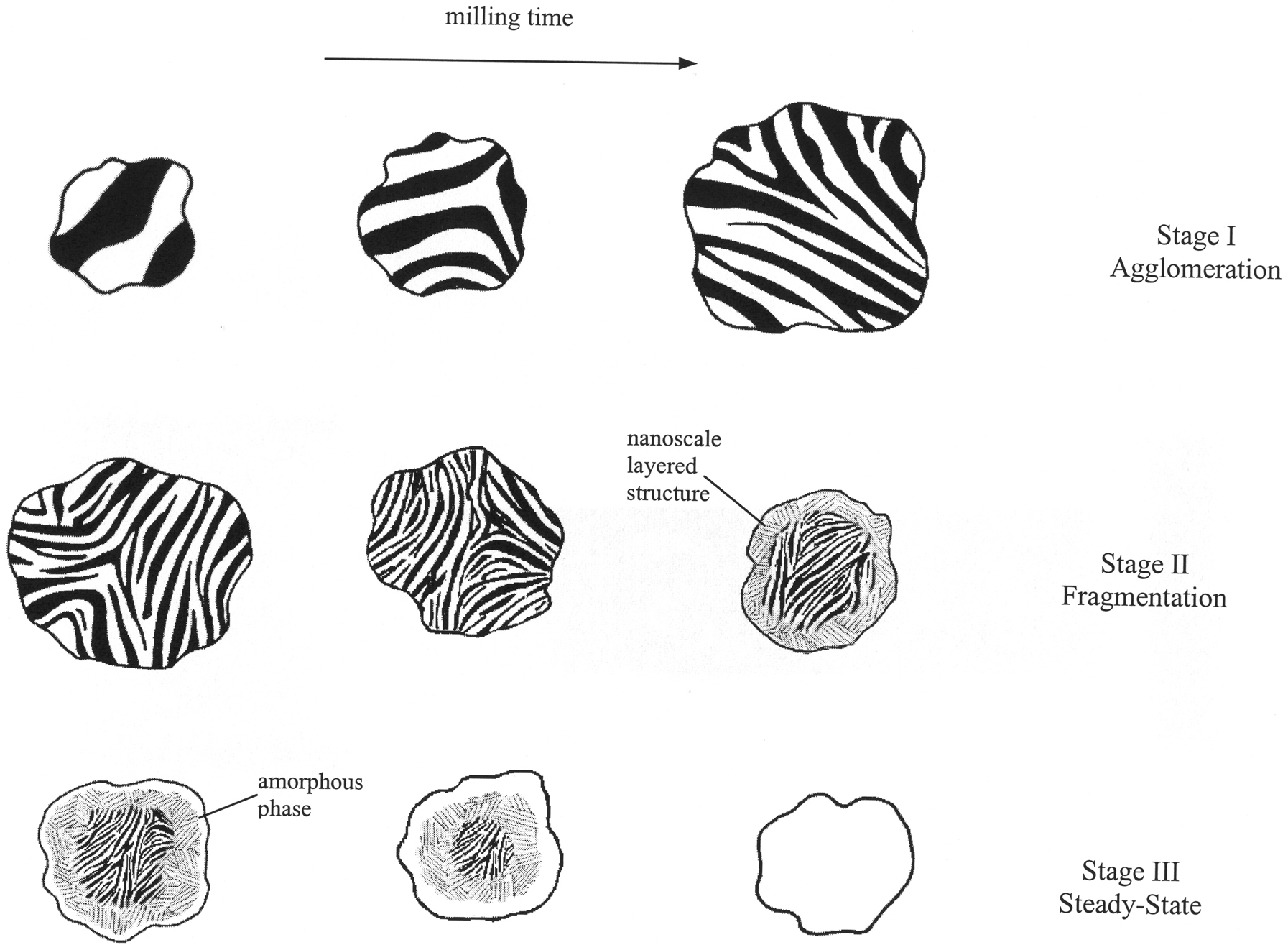
Schematic representation of evolution of powder morphology and structure during MA. Three stages are observed. stage I (agglomeration): Successive cold welding of Ni and Nb powder particles leads to a continuous increase in particle size. A layered structure is formed, with a progressively refined layer thickness with increasing milling time. Stage II (fragmentation): Fracturing process dominates. Powder particles and layers thickness refine. Owing to non-uniform plastic deformation a nanoscale layered structure develops at edges of particles late in this stage while centres exhibit a significant coarser layer. Stage III (steady-state): Powder particle size remains nearly constant. The strong and resilient amorphous layer formed at edges of particles prevents powder particles from further fracturing. However under impact force of colliding balls the region underneath can be plastically deformed and then transform to amorphous phase
Experimental observations suggest that MA amorphisation can occur through different paths. Most cases involve direct transformation of constituents to the amorphous structure after sufficient milling and no intermediate crystalline phase forms as a precursor to the amorphous phase. Whereas in some alloy systems a crystalline phase (i.e. solid solution, intermetallic phase) forms initially as an intermediate phase and then transforms to the amorphous structure on further milling.
Role of heat of mixing and atomic size mismatch
In contrast to solid-state amorphisation via annealing, a negative heat of mixing (ΔH mix) appears not to be a necessary requirement for amorphisation by MA. Solid-state amorphisation by MA is found in some alloy systems such as Fe–W (0 kJ mol−1), 108 Cu–W (33 kJ mol−1) 109 and Cu–Ta (3 kJ mol−1) 110 where the heat of mixing is almost zero or even slightly positive. In contrast, amorphous structures have not been obtained by annealing of the corresponding multilayer system. 111
The MA amorphisation mechanism in the absence of a negative heat of mixing is not well-understood yet. Chakk et al.
111
have proposed a theoretical model based on the atomic size ratio criterion. This model suggests that during ball milling process, under impact of colliding balls, the atoms with smaller size A can penetrate into the interstitial positions of the B lattice and thereby introduce local distortion of the lattice. When for a certain atom fraction of A in B this distortion reaches a critical value, the long-range order of the lattice is destroyed and the amorphous state is obtained. Based on the heat of mixing and the atomic size ratio, Chakk et al. constructed a diagram (Fig. 13) to analyse amorphisation in binary systems. Chakk et al. argued that pure elements and systems with low negative heat of mixing and small difference in atomic radii cannot be amorphised by MA and annealing whereas those systems which exhibit a large negative heat of mixing together with a large atomic size mismatch can be successfully amorphised by both methods. Alloy systems with a small negative heat of mixing, however, can be amorphised only by MA. Chakk et al. concluded that the negative heat of mixing can only facilitate the amorphisation reaction. In other words, a small negative or even slightly positive heat of mixing makes the amorphisation process more energy and time consuming but does not prevent it. One indication for this model is the work of Cocco et al.
112
who studied the glass formation of Ni50Mo50. With a combination of X-ray diffraction and X-ray absorption spectroscopy, they observed that the amorphous NiMo nucleated after an insertion of Mo into the FCC Ni lattice, until a critical internal stress was reached. This was followed by the fragmentation of crystallites and loss of long-range order. However, the authors pointed out that Mo atoms occupied substitutional position in the Ni lattice which is in contrast to model proposed by Chakk et al.
111
Furthermore it was suggested that the minimum solute concentration 

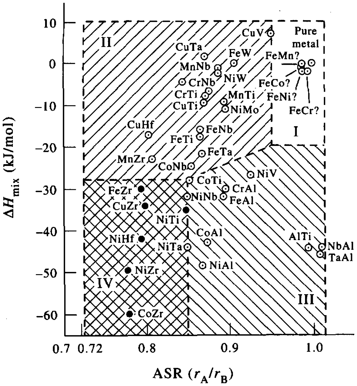
Heat of mixing (ΔH mix) versus atomic size ratio (r A/r B) map for prediction of the amorphisation tendency in binary alloy systems by MA. 111 Presence of either a large heat of mixing (regions III and IV) or a large atomic size mismatch (regions II and IV) is necessary for amorphisation by MA. Therefore the cases which fall into region I cannot be amorphised by MA
Amorphisation by MM (defects-induced amorphisation)
In MM, the starting material all has a single composition. Although no thermodynamic driving force for diffusion is available, still an amorphisation reaction can occur. Further in some MA cases, a crystalline intermetallic compound forms as a precursor to the amorphous phase during initial stages of MA of a multi-component system. In second stage this chemically homogeneous crystalline phase transforms to the amorphous structure on further milling. The subsequent transition from chemically homogeneous intermediate phase to the amorphous phase in second stage cannot be easily explained by the diffusion-induced destabilisation model as proposed by Johnson 100 and Schultz. 101
Johnson, 99 Schwarz and Koch 114 and Bakker et al. 102 proposed that the lattice defects produced by deformation during milling are responsible for MM amorphisation in a similar way as irradiation-induced amorphisation. The accumulation of lattice defects raises the free energy of the system from the equilibrium crystalline state G x to amorphous state G a. The thermodynamic condition for amorphisation can be defined as G x+ΔG d>G a where ΔG d is the free energy increase due to defects.
Energy can be stored in a deformed material in the form of defects such as vacancies, interstitials, dislocations, grain boundaries and atomic disorder. There is still much uncertainty regarding which defects play a major role in raising the free energy of the crystalline state. Dislocations have not been observed to be a significant contribution. Atomic chemical disordering and/or nanocrystalline grain boundaries are more likely sources of energy storage to induce amorphisation as suggested by Seki and Johnson 115 for MM of CuTi2, and by Cho and Koch 5,116 for MM of CoZr and Nb3Sn.
Considering only pure defects accumulation mechanism, it should be possible to amorphise pure elements. However, the amorphisation of pure Si, as a metalloid, is the only available case. 45 Partially amorphised Si powder has been obtained by ball milling of polycrystalline elemental Si with a purity of 99·9%. The volume fraction of amorphous phase was about 15%. The authors have suggested a pressure-induced amorphisation mechanism to describe the amorphisation of Si by MM. In case of Si, cubic diamond crystal structure (Si-I) transforms to β-Sn metallic phase (Si-II) at pressure of 11·3 GPa under hydrostatic compression at room temperature 117 and at stresses between 10 and 12 GPa in uniaxial shock-wave experiments. 118 Owing to the ball-powder-ball compression force, this polymorphic transformation can occur during MM process. Owing to the rapid unloading rate, it is possible that the high-pressure crystalline form of Si cannot transform back fast enough to the equilibrium structure so that the amorphous phase is formed. This mechanism is supported by recent finding of Gamero-Castano et al. 119 who reported amorphisation of single-crystal Si bombarded by nanodroplets.
Polymorphic (irreversible) or allotropic (reversible) phase transition below a critical grain size at room temperature has been also reported for several early transition metals (Ti, Nb, Zr). This phenomenon was attributed to the structural instability caused by negative hydrostatic pressure (from crystal-core to surface) due to formation of nanocrystalline structure and/or high strain rate deformation in MA/MM. 31–34
The crystal-to-amorphous transition in Si can be also explained by the defects-induced destabilisation. Partial amorphisation may be related to the presence of a non-uniform nanocrystalline grain size distribution. Only those regions that reach the critical grain size satisfy the thermodynamics condition and can transform. The critical grain size for amorphisation has been estimated to be about 3 nm for Si which is consistent with high resolution electron microscopy observations. 45
Solid-state amorphisation in both MM and MA processes is proposed to be aided by pumping in free volume (vacancies) and/or creating new atomic coordination (or short-range order) that renders long-range periodicity untenable. These two aspects have been extensively studied and explained by positron annihilation spectroscopy and nuclear magnetic resonance in case of solid-state amorphisation of Al–Ti–Si system. 120–122
To conclude, although the MM and MA amorphisation are not understood completely yet, it is clear that the high density of lattice defects such as vacancies, interstitials, dislocations, grain boundaries and specific surface area play an important role for the thermodynamics and the kinetics of the amorphisation reaction. They raise the free energy of crystalline system and destabilise it with respect to the amorphous state. On the other hand, the high defects density produced during milling aids the diffusion processes and therefore the amorphisation reaction. It has been suggested that for both MM and MA the rate-limiting step is the production of lattice defects by milling. 114
Amorphisation criteria
Mechanical alloying and rapid solidification are two different approaches for producing amorphous structures.
In rapid solidification process, if the cooling rate of the melt exceeds a critical value R c the crystallisation is precluded and amorphous structure is obtained. This implies that the alloys with lower critical cooling rate are better glass former and can be obtained in fully amorphous structure with a higher thickness. In other words, slower crystallisation allows a decreased critical cooling rate and enables stable BMG formation and fabrication by conventional casting techniques.
While rapid solidification starts with a homogeneous alloy melt and relies on preventing the nucleation and growth of crystalline phases, MA starts with elemental crystalline powders mixture and involves diffusion processes in the solid state. For ball milling process, the times required for amorphisation can be considered as a measure to compare the GFA of alloys. 123 Suryanarayana et al. studied the start time of MA amorphisation of Fe42X28Zr10B20 (X = Al, Co, Ge, Mn, Ni, Sn) powder mixtures based on XRD results. 124 They observed that the amorphisation are easier (shorter time) in alloys in which the number of intermetallics in the constituent Zr–X binary phase diagrams is higher. It was also concluded that the MA amorphisation is possible for those systems which include a large number of intermetallic phases in the corresponding equilibrium phase diagrams. In contrast, if there is a room temperature solid solution phase over a wide composition range in the phase diagrams, then the amorphisation is not easy. Comparison of MA amorphisation kinetics in different alloy systems basically relies on two parameters; the onset time (t o) and end time (t e the required MA time to form a fully amorphous structure) of amorphisation reaction. While t o shows the ease of nucleation of an amorphous phase across the layers interfaces in a particular system, the difference between the onset time and end time of amorphisation Δt = t e−t o is an indication of the growth rate of amorphous phase and implies how fast the amorphisation reaction proceeds. It is important to remember that the determination of start time of amorphisation, nucleation of amorphous phase, based on only XRD method limits the accuracy of data to the XRD resolution. To overcome this limitation Enayati 7 applied DSC in order to determine the onset time of MA amorphisation in Ni60Zr40 and Ni60Nb40 alloys. Differential scanning calorimetry is beneficial for determination of the onset time of the amorphisation reaction, since the presence of a small fraction of amorphous phase results in an exothermic peak corresponding to the subsequent crystallisation of the amorphous phase. Both Ni–Zr and Ni–Nb systems are known as easy glass formers and are therefore suitable systems for studying the amorphisation reaction during ball milling. The kinetics of the amorphisation reaction for Ni60Zr40 alloy were observed to be faster than that for Ni–Nb alloys. 7 The start time of the MA amorphisation reaction (t o) for the Ni60Zr40 alloy was after 10 h which is half the 20 h for Ni–Nb alloys. This observation is consistent with the criterion suggested by Suryanarayana et al. 124 as there exists much more intermetallic phases in Ni–Zr system compared to Ni–Nb system. Ni–Nb and Ni–Zr exhibit different thermodynamic properties, atomic size mismatch and plasticity behaviour. All of these parameters can influence the amorphisation reactions during MA. The start time of the amorphisation reaction is mainly determined by the rate at which the smaller atom Ni can diffuse in the lattice of Zr (or Nb). Since the atomic radius of Zr (1·60 Å ) is bigger than that of Nb (1·47 Å), it is predicted that Ni has a higher diffusivity in Zr than Nb. Furthermore the heat of mixing for the Ni–Zr system is −51 kJ mol−1 which is more negative than −32 kJ mol−1 for Ni–Nb system. This implies that a higher thermodynamic driving force is available for intermixing and thus amorphisation in the Ni–Zr system which favours the reaction kinetics by increasing the chemical diffusivity. Moreover, Zr attains a grain size of 21 nm during MA of Ni60Zr40, while Nb exhibits a larger grain size of 35 nm during MA of Ni60Nb40 after the same milling time of 10 h. 7 The higher volume fraction of grain boundaries in Zr aids the kinetics of the amorphisation reaction by accelerating the diffusion of Ni in Zr. The lower diffusion rate of Ni in Nb compared with Zr means that the amorphisation reaction in Ni–Nb alloys is postponed until an adequate density of lattice defects (i.e dislocations, grain boundaries) is created by continued milling. It is worth noting that the time for completion of amorphisation (t e) was 50 h for Ni60Zr40 and 85 h for Ni60Nb40 compositions. 7
Effect of milling conditions on amorphisation
Several variables of the milling process can be critical in controlling amorphisation, including milling energy, weight of powder, milling temperature and time.
There are several examples of systems in which the fraction of amorphous phase for a given composition is a function of milling energy and/or temperature. For example, Eckert et al. 13,43,125 demonstrated that if the milling energy was too high, Ni–Zr alloys which were amorphised at a low milling energy would exhibit crystalline structure. The effect of milling temperature and energy on amorphisation of some Ni–Zr compounds was also studied by Chen et al. 126 They concluded that the ultimate fraction of the amorphous phase decreases as the milling temperature increases. Moreover, the final fraction of amorphous phase increases with increasing milling energy. Those compounds with a higher hardness exhibited a greater fraction of the amorphous phase for the same milling conditions. Similar results have also been reported by Padella et al. 127 for Pd–Si, Suryanarayana et al. 128 for Ti–Al, Yamada and Koch 8 for TiNi, Takeuchi et al. 20 for Ni–Zr and Murty et al. 17 for Ti–Ni and Ti–Cu alloy systems.
These observations have been explained in terms of two competing processes occurring during the cyclic deformation introduced by ball milling, 8,129 namely: (i) the creation of lattice defects which increases the free energy of system and (ii) recovery which reduces the density of defects and therefore, the free energy of the system. The milling time for attaining a certain fraction of amorphous phase is determined by the balance between the relative rates of these two processes. Increasing milling energy and/or ball-to-powder weight ratio causes a higher rate of creation of defects, whereas higher milling temperature increases the rate of recovery and removal of defects. Consequently, different equilibrium rates and different end products can be obtained. The greater fraction of the amorphous phase for harder materials is related to the higher rate of work hardening in these materials which enhances the rate of creation of defects. 126 If the milling energy and/or ball-to-powder weight ratio is chosen to be too high, either a partially amorphised or a crystalline structure is obtained. Eckert et al., 13 Suryanarayana et al. 128 and Takeuchi et al. 20 argued that this is probably due to the generation of more heat during milling, which promotes the recovery processes or causes subsequent crystallisation of the amorphous phase.
Various attempts have been made to understand the crystalline-to-amorphous transition during MA in terms of milling energy. Abdellaoui and Gaffet 130 and Magini et al. 131 showed that neither the impact energy nor the frequency of impacts govern the amorphisation process in a planetary ball mill if taken separately, but the shock power (the product of impact energy and the frequency of impacts) determines the outcome of milling process. In several researches, it has been shown, for different materials, that the total energy imparted during milling is responsible for the amorphisation and formation of intermetallics during MA rather than the impact energy of the individual balls. 17,132–134
It should be noted that the total energy of milling proposed by Murty et al. 17 additionally includes further parameters such as the total number of balls, time of milling and weight of powder, in addition to the parameters contributing to shock power.
Various attempts have been also made to construct 3D or 2D milling maps for prediction of MA amorphisation in terms of milling parameters and thus identify the conditions required for amorphisation during MA. These maps involve different parameters such as impact energy and cumulative kinetic energy, 135,136 power absorption and degree of filling, 131 ball-to-powder weight ratio and milling time, 128 and the impact energy of the ball and the total energy. 17,133
Bhatt and Murty 137 recently reported an attempt to synthesise amorphous phase by MA in a number of BMG forming compositions in Zr, Ti, Fe, Cu and Ni based systems to develop milling maps/energy maps for the formation of amorphous phase. Milling parameters such as milling speed, ball-to-powder weight ratio have been varied over wide ranges in order to have a wide range of milling energies. The milling maps in Fig. 14 show the energy domains for amorphisation from the elemental blends. The results indicate that total energy of milling has a more decisive role than the impact energy of the balls in the formation of the amorphous phase by planetary ball mill. Milling energies in excessive of that required (shown as second dashed line on the right) for the formation of amorphous phase will lead to in situ crystallisation of the amorphous phase. This is caused by either the raise in temperature during milling, or due to large number of defects generated, which can enhance the diffusivity. Thus, there is definitely an energy window in which amorphous phase forms during MA. The energy required for amorphisation falls in a range of 500–600 J g−1 for all the compositions studied. Further amorphisation in all the compositions has been observed to occur below a critical crystallite size of about 20 nm as observed in Fig. 15. 137
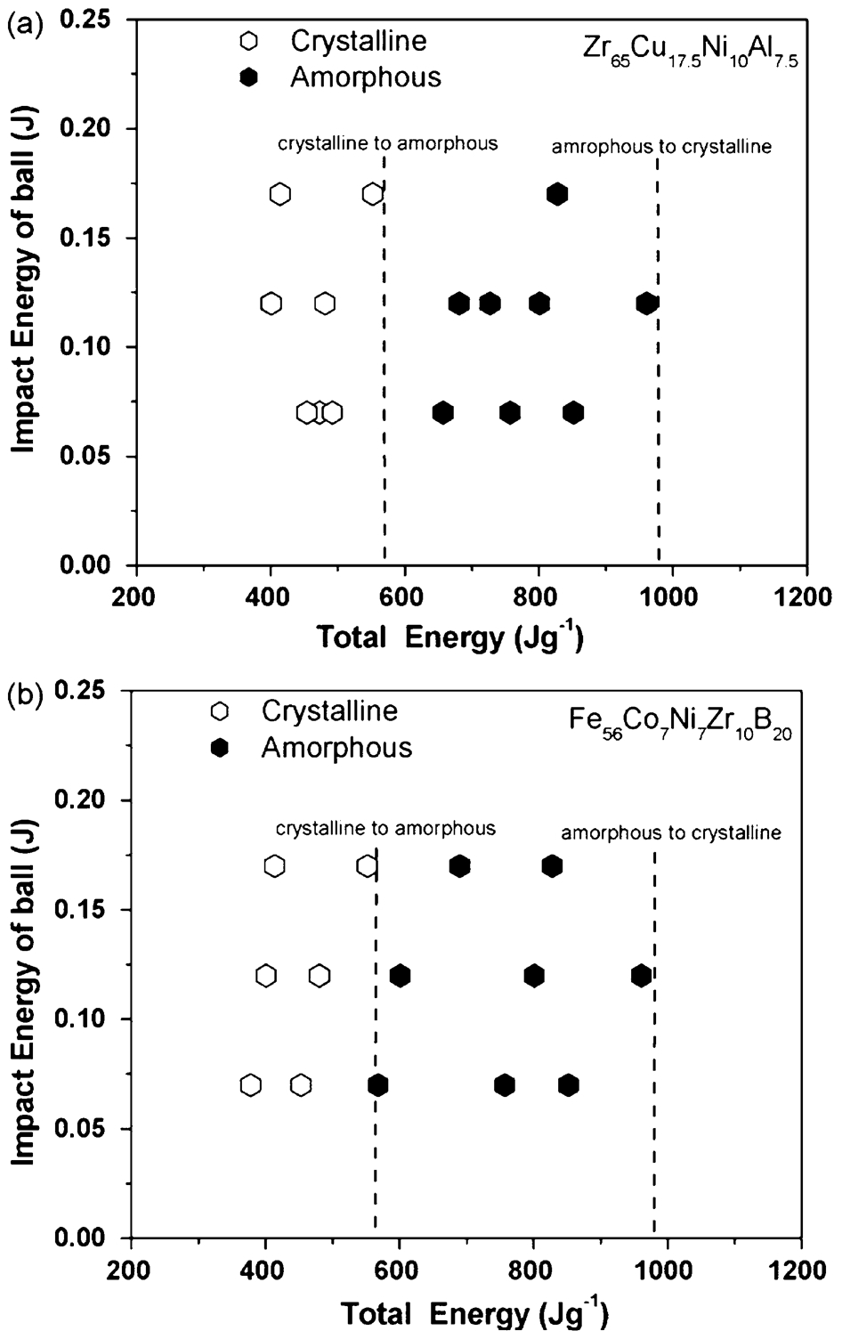
Milling maps indicating the energy required for amorphisation in a Zr65Al7·5Cu17·5Ni10 and b Fe56Co7Ni7Zr10B20 137
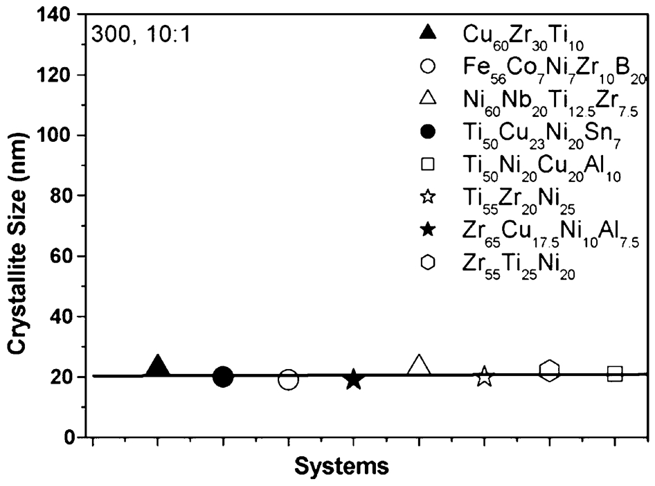
Crystallite size of various systems showing nano-formation as prerequisite of amorphisation 137
Amorphous alloy-based composite materials
In addition to the use of amorphous alloys as a single-phase material, there exists a broad range of composite materials that can be obtained by introducing crystalline phase(s) in the amorphous structures. The amorphous alloys exhibit useful properties such as high strength, high hardness, large elastic limit, good corrosion resistance, and superplasticity at high temperature. However, deformation of amorphous alloys by shear bands and their sudden failure similar to a brittle material is a barrier for using these materials in load-bearing applications. 138 Earlier studies demonstrated that preparation of amorphous nanocomposite, a microstructure consisting of nanocrystalline phases in amorphous matrix, is promising for improving the ductility of amorphous alloys. 139 Basically, such a structure can be readily achieved by (i) partial crystallisation either directly by quenching from the melt or through annealing of amorphous precursor structures, (ii) partial amorphisation during ball milling, and (iii) blending a metallic glass with insoluble metallic (W particles 140,141 ) or ceramic particles (oxide 140,142 carbide 143 or nitride 144 ). The crystallisation process can be executed by thermal treatment or alternatively by plastic deformation. Both options can be applied during a separate subsequent process or during consolidation of amorphous powder to produce bulk materials.
The mechanical properties of amorphous-based nanocomposite have been found to be very promising as they possess both outstanding tensile strength and good ductility at room temperature. Hence, this class of materials seems to be superior to single-phase nanocrystalline materials which typically exhibit little ductility in tension for grain sizes smaller than about 25 nm.
For example, Kim et al. 145 and Inoue et al. 146 developed amorphous Al88Ni9Ce2Fe1 based nanocomposite by partial crystallisation of the melt-spun amorphous ribbon. The microstructure of partially crystallised alloy consists of 25 per cent volume fraction of fcc-Al particles with a size of 3–5 nm and a mean distance of 10 nm dispersed within an amorphous matrix. While the tensile fracture strength of Al–Ni–Ln (Ln = Y, La or Ce) amorphous has been reported to exhibit levels up to 1000 MPa, by partially crystallising A188Ni9Ce2Fe1 amorphous alloys the tensile strength reaches as high as 1560 MPa which is about three times more than that of conventional high-strength Al alloys. Nano-sized fcc-Al particles are yielded by controlled primary crystallisation of amorphous aluminium alloys. Similar microstructure are possible when using mechanically alloyed amorphous powders as starting materials. 147 Inoue and Kimura 148 showed that five types of non-equilibrium structures can be obtained by controlled crystallisation of Al-based amorphous alloys including; (1) nanostructure consisting of crystalline Al and compounds, (2) partially crystallised structure of nanoscale fcc-Al particles embedded in an amorphous matrix, (3) nano-quasi-crystalline structure consisting of nanoscale quasi-crystalline particles surrounded by Al phase without grain boundary, (4) coexistent nanogranular amorphous and Al phases, and (5) nanogranular Al phase surrounded by an amorphous network. It is notable that the density of nanocrystal in amorphous matrix can attain high levels of 1021–1025 m−3 to yield ultra-high strength. These non-equilibrium Al-based alloys exhibit much better mechanical properties as compared to conventional crystalline alloys developed up to date. Figure 16 schematically illustrates the microstructure and the mechanical strengths of these structures. 148
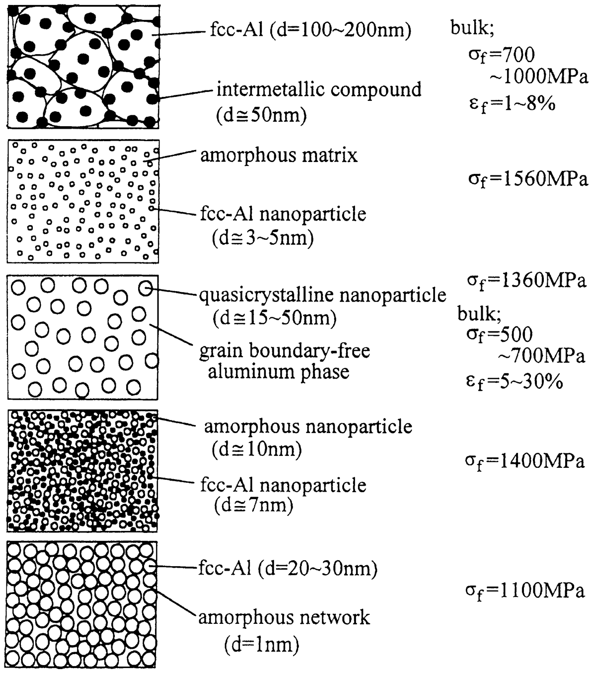
Schematic illustration of microstructure and mechanical strengths of five types of non-equilibrium structures obtainable by crystallisation of Al-based amorphous alloys. 148
Similar microstructures have been developed in other amorphous alloys. For example, in partially crystallised Mg-rich alloys with more than 80 at-% Mg, nanoscale hcp particles (5–10 nm) are dispersed homogeneously in the amorphous matrix with a typical interparticle spacing of about 3–10 nm. 149,217 This structure provides higher tensile strength, hardness, Young’s modulus and better room temperature ductility compared to the fully amorphous alloy. For Mg–Zn–La alloys the ultimate room temperature tensile strength increases from about 600 MPa for the amorphous phase to about 700 MPa for nanocomposite structure containing nanoscale hcp Mg particles. 149,217 Higher room temperature ductility is attributed to the homogeneous dispersion of ultrafine (5–10 nm) hcp particles embedded in the amorphous matrix which act as effective barriers for local shear deformation and assist homogeneous plastic deformation as long as the amorphous matrix phase exhibits some ductility. Similar results have been reported in case of Zr-based amorphous nanocomposite prepared by partial crystallisation of amorphous structure. 150–157
To obtain a high density of ultrafine crystalline particles, the crystallisation process should occur with a high nucleation rate while the growth rate being kept at a low level. Generally, it is also possible to produce a nanocrystalline structure directly by proper cooling of a melt in which the solidification proceeds by homogeneous nucleation. However, the released latent heat during solidification reduces the extent of supercooling and therefore the nucleation rate. The key strategy in achieving the nanocrystalline structure by crystallisation route is to provide a high nucleation rate, while the latent heat of crystallisation releases with low rate. These conditions can be readily accomplished during crystallisation of a solid amorphous structure where the crystallisation occurs at low temperature around T g at which the growth rate is quite small. 158
The amorphous-based nanocomposite by ball milling route can be achieved via several approaches as summarised in Fig. 17. Incomplete ball milling is the most straightforward approach. This leaves ultrafine crystalline phase(s) of constituents in the amorphous matrix. Figure 18 shows a typical microstructure obtained by incomplete amorphisation reaction in case of MA of Ni60Nb40 alloy. In this approach, the extent of amorphisation is either thermodynamically or kinetically limited by proper choosing the composition or milling parameters. Crystalline phase(s) can be also introduced in amorphous matrix by ball milling of amorphous phase constitutes with insoluble metallic or ceramic particles as reinforcement phase. The insoluble particles are repeatedly broken to smaller size and dispersed in the matrix simultaneously with development of amorphous structure. Yet another way for making amorphous-based nanocomposites by ball milling is to utilise the reaction of constituents with milling atmosphere or the reaction between constituents themselves (MX+R→RX+M) to obtain the reinforcing phase (RX). For example, MA of Mg–Y–Cu powders led to in situ development of amorphous-Y2O3 nanocomposites during processing. 143 XRD and TEM investigations revealed that the structure of powders contains nanoscale unreacted elemental material and traces of 10–20 nm Y2O3 crystals homogeneously embedded in the amorphous matrix. Oxide phases are introduced mainly because of a reaction between constituents and milling atmosphere; also, they might have resulted from fracturing and dispersion of pre-existing oxide layer on surface of powder particles. 143 It was found that the thermal stability of the amorphous matrix alloy is not markedly affected by the presence of the nanoscale Y2O3 dispersoids. The powders exhibit a supercooled liquid region of about 40–50 K, similar to that of melt-spun ribbons, 143,159,160 allowing an easy consolidation of these powders by hot pressing or extrusion in the viscous state above T g. The Vickers hardness and fracture strength of consolidated samples were reported to be about 345–385 HV and 1150–1280 MPa depending on composition. 141,159,161 These values are significantly higher than those for as-quenched amorphous or partially crystallised ribbons or cast bulk specimens. 162,163 Mg-based amorphous nanocomposite has been also synthesised by ex situ addition of MgO, CeO2, Cr2O3, or Y2O3 oxide particles. 164 In this way, the addition of oxide particles is not limited to a small volume fraction as is the case with in situ processing. Zr-based amorphous nanocomposites were also prepared directly via MA, by blending the metallic constituents of the amorphous phase with insoluble oxide, 140,142 carbide 143 or nitride 144 particles. The high density of nanoscale metallic or oxide particles, i.e., a small interparticle spacing, provides superior mechanical strength after MA and also after consolidation. Dastanpoor et al. utilised mechanochemical reaction between CuO and Al powders to obtain Cu–Zr–Al/Al2O3 amorphous nanocomposite. 165 Cu60Zr40 intermetallic compound was first synthesised by melting of Cu and Zr. The Cu60Zr40 intermetallic compound was then ball milled with Al and CuO powders. The MA of Cu60Zr40, Al and CuO powder mixture for 10 h led to the reaction of CuO with Al, forming Al2O3 particulate, and concurrent formation of Cu62Zr32Al4 amorphous matrix. Nanoindentation tests showed that Cu62Zr32Al4–10 vol.-% Al2O3 amorphous nanocomposite had a hardness value of 837 HV and an elastic modulus of 90 GPa which are higher than those for Cu60Zr40 and Cu50Zr43Al7 amorphous alloys. In another work, nanocomposite structure containing amorphous matrix surrounding nanocrystals was synthesised by MA of (Ti69·7Nb23·7Zr4·9Ta1·7)100−x Fe x for x = 2 and 6 whereas for x = 0 and 10 full nanocrystalline and full amorphous structures were achieved, respectively. 166 Kumaran et al. 167 developed TiAl–Nb2Al nanocomposite powders by high-energy ball milling from a mixture of prealloyed TiAl, niobium, aluminium and SiC powders. The final microstructure included nanocrystalline TiAl, amorphous phase and TiAl–Nb2Al intermetallic nanocomposite powders with varying Nb and Al concentrations. Amorphous-based nanocomposite containing Mg2Ni phase, some residual Ni and an amorphous phase was prepared by MA of a mixture of Mg and Ni with an atomic ratio of 2 : 1 at a certain milling intensities. 168 This structure had improved hydrogen storage characteristics. Rodríguez and Botta 169 performed high-energy milling on Al90Fe5Nb5, Al90Fe7Nb3, Al90Fe5Cr5 and Al90Fe7Zr3 alloys to produce Al-based amorphous alloys. Milling of all composition resulted in partially amorphised structure containing intermetallic compound. These results clearly demonstrate that nanocomposites with an amorphous matrix and metallic/non-metallic nanocrystals can be directly obtained during ball milling process by careful adjusting of powder compositions as well as milling parameters (i.e. intensity, time, temperature and atmosphere of milling). On the other hand, amorphous powders prepared by ball milling can be used as a precursor for producing nanocomposites through controlled devitrification.
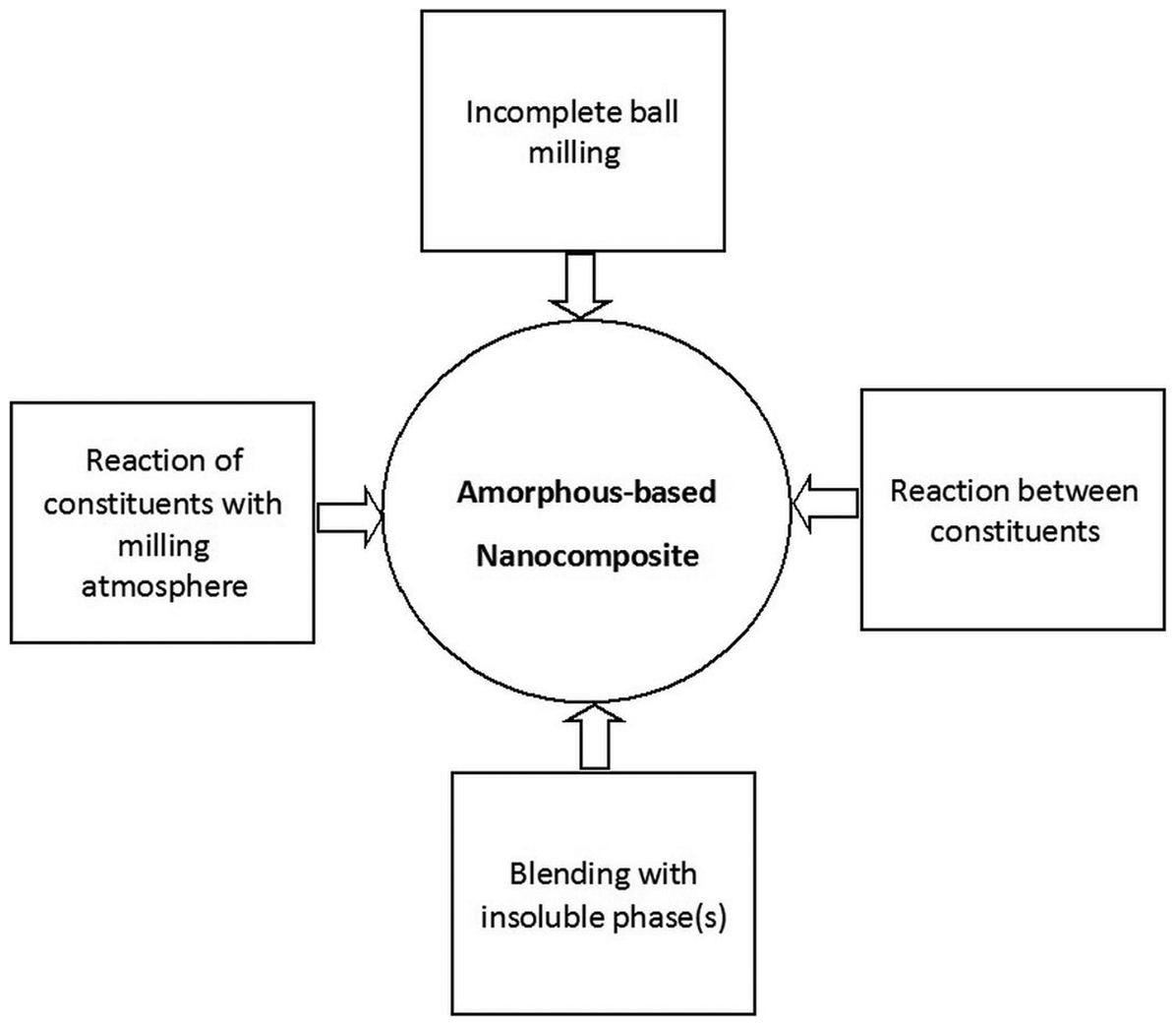
Different possible routes for synthesis of amorphous-based nanocomposite by ball milling process
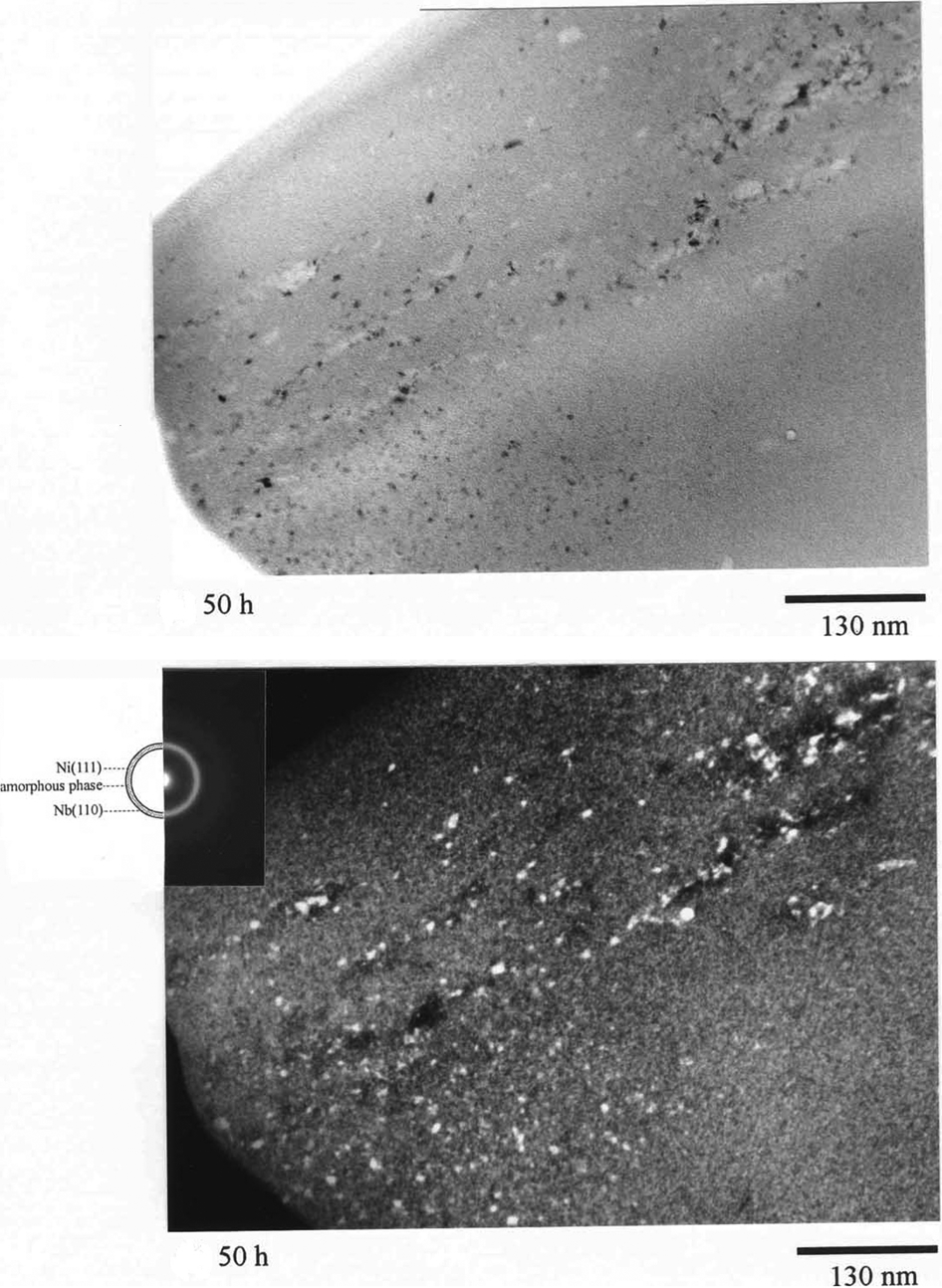
Transmission electron microscopy (TEM) images and corresponding selected are diffraction patterns of Ni60Nb40 powder particles after 50 h of milling time 7
Bulk nanocrystalline/amorphous alloys prepared by consolidation of mechanical alloying/mechanical milling powders
Mechanical alloying/mechanical milling products are in the form of powder. Application of amorphous/nanocrystalline powders prepared by MA/MM requires efficient methods of consolidation. Several requirements should be fulfiled during consolidation to produce bulk components with desirable structure, shapes and sizes including:
suppressing undesirable phase transformations (crystallisation, grain growth, phase coarsening, etc.) during consolidation;
achieving full density by removing all porosity;
achieving strong particulate bonding.
Both porosity removal and interparticle bonding occur by diffusional process which is accelerated at high temperature. On the other hand, the diffusional transformations like crystallisation of amorphous phases or grain growth of nanocrystalline structures must be also avoided during consolidation, suggesting that the consolidation time and/or temperature should be selected as low as possible. Conventional techniques often involve two steps of cold compaction, to obtain crack free green bodies, followed by sintering at high temperature. Mechanical alloying/mechanical milling powders are severely work hardened and thus have low compressibility making it difficult to form the green compact with high density. Therefore, high temperature and long time must be applied during sintering to produce dense components with good interparticle bonding. As a result, enhancement of the densification rate and concomitant restriction of crystallisation or grain growth during consolidation have been found to be difficult using conventional pressureless sintering techniques.
To fulfil the requirements in processing of bulk nanocrystalline/amorphous materials, i.e. enhancing densification while suppressing undesirable microstructural transformations and coarsening various approaches have been developed in which the densification is activated by applying an external factor in order to reduce temperature and/or time.
Application of a high external pressure during sintering aids pore shrinkage and densification of powder particles. Sintering assisted with pressure has been found to be an effective technique for obtaining fully dense bulk nanocrystalline/amorphous components. In this way, closure of the porosity occurs by plastic deformation and material flow into the pore which increases the number of particle contacts. This is particularly important for elimination of very large pores which are not normally removed by diffusion in any reasonable length of time. Under applied stress, another sintering mechanism known as stress-assisted diffusion mechanism is also activated. 170 Furthermore, applied pressure can change the phase transformation products during consolidation. For example, it is reported that application of high pressure affects crystallisation of Al85Fe15 amorphous alloy prepared by MA. 171 Al13Fe4 phase and fcc-Al are the crystallisation products after heating of Al85Fe15 amorphous alloy in the calorimetre (under atmospheric pressure). While consolidation of Al85Fe15 amorphous powder at high pressure (7·7 GPa) yields metastable phases different from those obtained during calorimetry experiments.
Numerous pressure-assisted consolidation techniques have been successfully utilised for full densification of ball milled powder with minimal microstructural coarsening and/or undesirable microstructural transformations. This includes hot pressing, vacuum hot pressing, hot isostatic pressing (HIP), hot extrusion, sinter forging, spark plasma sintering (SPS) and shock-wave consolidation. Generally, the extent of shear stress component induced by external pressure determines the capability to collapse the pores. The shear stress is minimal in HIP and increases gradually from quasi-isostatic pressing to uniaxial pressing in a die (hot pressing), to uniaxial pressing without a die (sinter-forging) and finally to extrusion. 172 Further the shear stress breaks the surface oxide layers on particles improving interparticle bonding.
Another method of activated sintering is SPS which simultaneously utilises the effects of two activating phenomena during sintering; a pulsed current discharge along with an applied pressure. This technique is sometimes referred to in the literature as field-assisted sintering, plasma pressure consolidation, plasma-activated sintering, pulse electro-discharge consolidation and pulsed electric current sintering. In SPS, powders are placed in a die (typically graphite) and heated by passing an electric current (often pulsed DC) through the die and the sample (if sample is conductive) while a pressure is applied on the powder. The main benefit of SPS process compared to other pressure-assisted sintering techniques is related to the effect of the pulsed electric current. A current, up to 20 000 A, is sent through the graphite die and for conductive powder through the sample itself which heats the sample to high temperatures with a rate as high as 1000°C min−1. For conductive sample, the pulsed electric current is believed to have several additional effects on sintering process. Formation of sparks at the initial of each pulse between the gaps of compacted powder particles can create high temperature plasma (spark plasma). The spark and/or plasma discharges clean the surfaces of the powders from adsorbed species such as CO2 and H2O and create various types of surface defects. The cleaned and activated surfaces are expected to enhance the diffusion and densification process. 173 Furthermore, it is likely that the pulsed current promotes the mass transfer thus facilitates densification due to a change in defect concentration 174 or enhanced mobility of the defects. 175 The use of extremely high heating and cooling rates, very short holding times along with high pressure allow rapid consolidation while retaining the amorphous or nanocrystalline structure. Microwave sintering benefits from volumetric heating of green compact caused by microwaves coupling with individual powder particle. This leads to the uniform rapid heating of sample with reduced thermal stresses. The structural transitions can be suppressed by rapid heating and cooling rates and short holding times. Further, there are some evidences which indicate that an alternating microwave electromagnetic field may have some non-thermal effects such as improved densification by promoting atomic diffusion. 176,177
Mula et al. 178 compared three consolidation processes, SPS, hot-pressing and pressureless sintering, for preparation of high strength bulk Al-based nanocomposite consisting of nano-intermetallic particles and amorphous phase by consolidating mechanically alloyed amorphous Al88Ni6Ti6 powder. They reported that SPS technique was the most effective process in terms of homogeneity of microstructure, densification and mechanical properties due to lower sintering temperature and time which limit excessive crystallisation of amorphous phase and grain growth of formed nanocrystals.
As mentioned, to avoid undesirable structural change during consolidation the densification time and/or temperature should be selected as low as possible. In shock-wave or dynamic consolidation, the powdered materials are packed in a capsule which is then subjected to explosives or high velocity impact. This produces a shock wave with a high pressure, in the order of several GPa, for a very short duration, in the order of a microsecond. This causes powder particles to be plastically deformed with an extremely high strain rates (usually greater than 103 s−1). Rapid deformation and packing of powders rise the particles surface temperature rapidly while their interior temperature remains almost unchanged. The densification occurs in a very short time by localised melting at the interfaces between the powder particles. In this technique, application of a prompt high pressure and consolidation at low temperatures in a very short time allow full densification of powders without any significant coarsening or phase transitions. Examples of dense materials that have retained nanocrystalline structure by pressure-assisted sintering are provided in Table 1.
Examples of dense nanostructured materials prepared by mechanical alloying/mechanical milling followed by a consolidation step
Nanocrystalline structure can be stabilised against excessive grain growth during consolidation or subsequent high temperature treatment by use of grain growth inhibitors. Residual pores,
192
impurity/solute atoms,
193
and second phase particles (Zener drag)
194
have been shown to influence the grain boundary mobility in nanocrystalline materials, and in turn may strongly affect kinetics of grain growth involved. Pinning of grain boundary by suitable second phase particles has been found to be the most efficient method of retarding grain growth. Based on Zener drag mechanism the drag pressure (P) on a boundary of energy γ per unit area due to particles of radius r and volume fraction of f is expressed as
This expression anticipates that there exists a significant pressure if fine insoluble particles with high volume fraction are incorporated in the matrix. In fact, added thermal stability for cryomilled nanostructures was attributed to the pinning of grain boundaries by an inherent dispersion of second-phase Al2O3, AlN, and Al4C3 particles that results naturally from the cryomilling process. 58,195,196 For instance, cryomilled nanocrystalline Zn–22 wt-% Al showed excellent stability during annealing at 543 K (0·77T m) so that the grains remained in nanometre range (<100 nm) even after annealing for 72 h. 56 In a related study, Zhou et al. 58 reported a high degree of grain size stability for cryomilled nanocrystalline Al even after long annealing at temperatures as high as 0·78T m. Cryomilling seems to be a promising technique for synthesis of nanocrystalline powder with high thermal stability which can be subsequently formed to bulk materials by proper conventional consolidation methods without losing the nanocrystalline structure. In this regard, it is worth mentioning the work of Tellkamp et al. 60 who produced bulk nanostructured 5083 Al material with 99·6% theoretical density using several processing steps; cryomilling of spray-atomised 5083 Al powders, hot-vacuum degassing at 573 K and then hot pressing (523 K) and extrusion (523 K). By this procedure, they were able to fabricate nanostructure 5083 Al alloy which was stable up to 0·61T m. The average grain size was 24 nm for as-milled powder which increased only slightly to 34 nm after extrusion. The excellent thermal stability was attributed to Zener pinning of grain boundaries by AlN and Al2O3, introduced by breakup and distribution of powder surface oxide layer during deformation in ball milling, as well as solute drag. The consolidated samples additionally exhibited excellent tensile properties with a yield and ultimate strengths of 334 and 462 MPa respectively. These values are 30% greater than those for strongest commercially available form of 5083 Al, with no corresponding decrease in elongation/ductility.
More recently, Maung et al. 197 evaluated the effect of diamantane on stability of Al nanocrystalline structure. Diamantane is a diamondoid molecule consisting of 14 carbon atoms in a diamond cubic structure that is terminated by hydrogen atoms. It has a size of ∼2 nm with fascinating properties, such as high hardness and stability, which make it a potential candidate as grain growth inhibitor. Commercially pure aluminium powders were cryomilled with 1 wt-% diamantane for 8 h producing powders with an average grain size of 22 nm. This material exhibited greater thermal stability than cryomilled pure Al in the temperature range of 423–773 K (0·45–0·83T m). Specifically, the grain size of cryomilled Al+1% diamantane was consistently found to be less than half of that for cryomilled pure Al under the same thermal exposure conditions. The grain size remained nanocrystalline (<100 nm) for Al+1% diamantane, even after 10 h at the highest temperature of 773 K. 197
It is to be noted that following primary consolidation, secondary processing is sometimes performed to remove any remaining porosity and improve mechanical properties. For example, Sadeghian et al. 198,199 produced Al–20 wt-% TiB2 metal matrix nanocomposite powder by MA of pure Ti, B and Al powder mixture. The resultant powder was consolidated by SPS followed by hot extrusion. The results showed that the prepared Al–20 wt-% TiB2 nanocomposite has good thermal stability against grain growth and particle coarsening. Extruded Al–20 wt-% TiB2 showed a hardness value of 180 HV and yield and tensile strengths of 480 and 540 MPa, respectively, which are much higher than those reported for similar composites made by other processes.
Crystallisation is a predominating problem that has to be overcome during consolidation of amorphous powder. To avoid crystallisation while achieving full densification, the amorphous powders should be consolidated in the temperature range between the glass transition temperature (T g) and crystallisation temperature (T x), where the viscosity of the amorphous phase drop by several orders of magnitude. Thus, the amorphous powder can be readily consolidated in the supercooled liquid region without the need for high temperature sintering. This is practically possible only if the amorphous structure exhibits a wide supercooled liquid range (ΔT x = T x−T g). Consolidation in the supercooled liquid region has been successful in most amorphous systems using techniques such as SPS, 200,201 HIP, 202 vacuum hot pressing, 203–205 and hot extrusion. 206 For example, Al75Ni10Ti10Zr5 bulk amorphous alloy (T x = 790 K and ΔT x = 49 K) with a diameter of 10 mm and thickness of 2 mm was obtained by MA followed by vacuum hot pressing at 733 K for 20 min under a pressure of 3 GPa. 205 In another attempt, cylindrical fully amorphous samples of Ni59Zr20Ti16Sn5 alloys with diameter of 8 mm and height of 10 mm were fabricated by consolidation of mechanically alloyed amorphous powder using HIP under a pressure of 1·5 GPa at 843 K for 0·5 h. 202 More examples on amorphous bulk materials prepared by consolidation of amorphous MA/MM powders are given in Table 2.
Bulk amorphous materials prepared by consolidation of amorphous mechanical alloying/mechanical milling powders
The results reported on consolidation of amorphous powder prepared by either pulverising of amorphous melt-spun ribbons or by MA/MM of powders show that by proper adjusting consolidation parameters (time, pressure, temperature) fully dense bulk metallic amorphous alloys could be obtained by compaction of amorphous powders within their supercooled liquid range. Therefore, powder consolidation can be considered as an alternative route for the preparation of bulk amorphous materials in alloy systems which are difficult to be prepared by casting methods because of their low GFA.
As mentioned in the previous section another synthesis option of bulk nanocrystalline/nanocomposite materials is based on controlled crystallisation of amorphous bulk materials.
Summary
Mechanical alloying/mechanical milling is a solid-state process which involves ball milling of powders in a high-energy mill. Severe plastic deformation, intensive work hardening, repeated cold welding and fracturing of powder particles during milling provide the means to synthesise novel materials with very fine microstructure and even non-equilibrium phase. While some aspects of the process, in particular the mechanisms behinds the accompanied phase transformations, are not well-understood, it has been clear that by controlling processing parameters, various classes of materials can be obtained. This has made MA/MM useful for producing nanostructured and amorphous materials.
Mechanical alloying/mechanical milling offers a non-equilibrium processing route of materials with large quantities and at low-cost relative to some other fabrication techniques. Materials production can take place at room temperature which can have advantages over high temperature synthesis. Additionally, the range of obtainable microstructures is much wider in case of ball milling process. However, several issues have restricted the potential application fields of powders processed by MA/MM. These include the contamination, arising from the milling media and atmosphere, and adhesion of powder particles on milling surfaces. Furthermore, the final material resulting from ball milling is in the powder form with a highly unstable structure (e.g. nanocrystalline, amorphous). Thus, significant structural changes can occur in the ball milled powder upon thermal treatment such as sintering and consolidation processes. In spite of introduction of several advanced techniques, such as SPS, at present consolidation of ball milled powders into bulk, full-density material with useful shapes and sufficient size without significant structural changes is still a critical challenge.