
Abstract
Inkjet printing offers controlled placement of both biological and synthetic materials. The precision, control and small working volumes associated with inkjet printing are advantageous where biological materials such as proteins, enzymes and cells can incur high costs. This review is primarily technology focused and divides bioprinting into three categories of interest: proteins, cells and scaffolds and demonstrates that the logistical hurdles and material formulation requirements remain a common denominator to the advancement of the field into commercial applications and three-dimensional (3-D) constructs. A variety of cell types printed using thermal, piezoelectric and electrostatic actuation mechanisms yield 80–95% cell viability. Transient membrane damage is reported for cells printed using a thermal printer. Protein deposition by thermal and piezoelectric printing results in reversible deformation leading to an increased need for the addition of ink modifiers. The fluid characteristics and the drop substrate interactions are identified as crucial with regards to future applications. The current approaches to scaffold matrix selection with regards to the complex criterion require fluid and solid phases and a controlled phase change while maintaining the criterion for printing vary from chemical gelation, physical gelation mechanisms (e.g. thermo reversible gels) and tandem gelation.
Introduction
There are a number of applications of biotechnology where either the precise placement of very small volumes of defined material or a high resolution patterning/decoration of a substrate is necessary. These include sensors (based on enzymes, antibodies or whole cells), microarrays (of proteins/peptides, DNA/RNA), patterns of biochemicals for cell guidance, tissue engineering scaffolds and hybrid cell-containing hydrogel structures. One technology that can achieve these desired structures is inkjet printing. 1,2 Inkjet printing for biological applications is still in its infancy and as such this review is primarily technology focused.
Inkjet printing was originally developed as a graphics and text printing method. It is a digital printing technology in that the image is constructed by the presence or absence of discrete drops of ink on the printed substrate. The printing process can be considered as two distinct processes: (1) the formation of individual drops that are directed to a specific location on the target substrate and (2) the interaction of the drop with the substrate during and following impact. There are two different methods used to form the drops of ink used in printing. These are continuous inkjet (CIJ) printing and drop-on-demand (DOD) inkjet printing. The mechanisms that lead to drop formation in these cases have been reviewed in detail elsewhere 3 but are described briefly here. Continuous inkjet printing exploits the natural tendency for a stream of liquid to undergo a morphological transformation to a train of discrete drops (the Rayleigh-plateau instability). With CIJ the ink is electrically conductive and the drops are charged as they form, these drops can then be steered to their desired location by electric or magnetic fields. Drops not required for the image are captured and re-circulated. Drop-on-demand printing, in contrast, produces a drop when required and drop placement is achieved by positioning the drop generator above the desired location before a drop is ejected. Both printing mechanisms are used in commercial printing devices with CIJ operating at higher drop generating frequencies (>>10) and DOD inkjet printer working at lower frequencies but achieving smaller drop volumes and hence greater image resolution. Continuous inkjet printed drops are typically twice the size of the orifice whereas DOD inkjet printed drops are comparable to the orifice diameter. 4 The resolution of any printed drop is linked to its surface interactions which in turn dictate the degree of spreading and the final drop footprint. 5 Typical inkjet printers generate drops with volumes in the range 1–100 pL and with typical contact angles these spread to a footprint of radius 10–50 μm, which is approximately the achievable resolution.
Drop-on-demand printers have been favoured for most applications where inkjet printing is used for material deposition because of their precision and the conservation of ink. 6 In biological applications, CIJ would lead to issues of sterility with ink recirculation and waste if the unwanted ink was discarded, hence to the best of our knowledge, all prior work using inkjet printing for applications in the biological and medical sciences have used DOD technology.
Drop-on-demand printers generate drops through a mechanical actuation of the fluid generating a pressure pulse. On reaching the printing orifice, a drop is generated if the pulse has sufficient energy to overcome viscous and surface tension forces. 3,6,7 The desired mechanical actuation can be achieved in a number of ways, with the most widespread being thermal, piezoelectric and electrostatic actuation. The actuation methods for thermal and piezoelectric DOD printing are shown schematically in Fig. 1. In thermal printing (Fig 1a ), a compact thin film resistive heater is used to form a small vapour pocket or bubble; on removing the heat the bubble collapses. The rapid expansion and collapse of the vapour pocket provides the necessary pressure pulse in the fluid for droplet ejection, Fig. 1b illustrates the method for pulse formation in piezoelectric printing; this is achieved by direct displacement of the fluid filled chamber wall through the use of a piezoelectric crystal. Electrostatic printing uses the same displacement mechanism but this is now achieved using a micro-electromechanical system (MEMS) actuator. Thermal printers are cheaper to manufacture than piezoelectric or electrostatic actuated devices, hence small ‘desktop’ printers used for general small scale graphics output tend to be thermal printers. However, a wider range of inks can be deposited by piezoelectric and electrostatic DOD printers; because there is no need for a low boiling temperature solvent, thus most largest scale industrial and laboratory based printers use this technology.
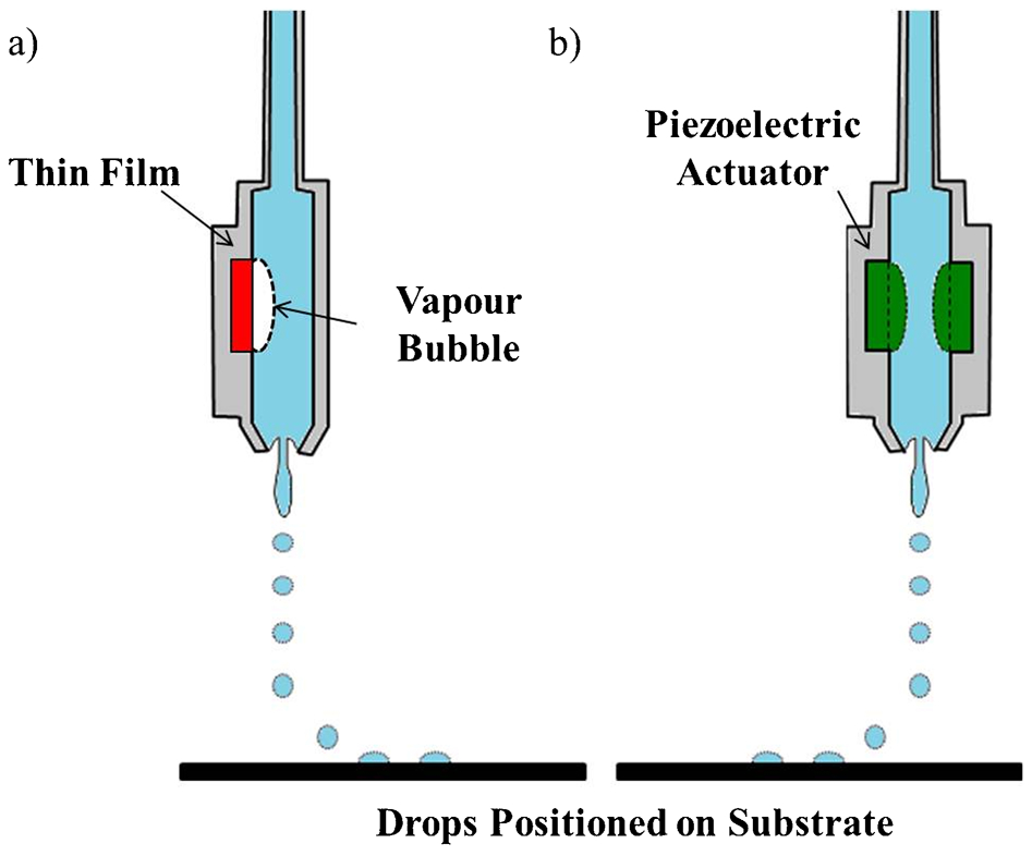
Schematic representation of drop formation in drop-on-demand (DOD) inkjet printing: a thermal printing and b piezoelectric printing. Republished with permission from Ref. 6
Drop-on-demand inkjet printing as a means of patterning or dispensing biological materials holds several advantages over conventional methods. The drop-on-demand nature of this technology means that drops are only dispensed when required, hence eliminating unnecessary wastage of potentially expensive fluids. The drops can be dispensed in controlled locations and, by utilising overprinting, in controlled surface concentrations.
Printing for biomedical applications can be separated into tiers of complexity. The simplest of which, is surface patterning using biological molecules such as proteins and enzymes to form sensor or array structures. The most complex is the full three-dimensional (3-D) construction of a tissue analogue structure. This article presents a review of the inkjet printing of biological components and discusses the challenges currently faced in the field.
Fundamental aspects of inkjet printing
Authors are confining this review to applications of DOD printing. As with all inkjet technologies, this is a liquid dispensing method and thus the source material must be a fluid ink or ‘bioink’ with its physical properties within a defined range of properties. Fromm suggested the following grouping of physical properties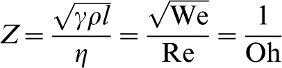
The upper image is a high speed photograph of a drop emerging from a drop-on-demand nozzle. Optimised printing parameters result in the ligament catching up with the leading edge forming a complete drop. The lower image shows a high speed photograph of a drop following detachment from the nozzle. Here, the ligament is breaking up to form satellite drops. Reproduced with permission of IOP Publishing. All rights reserved from Ref. 3
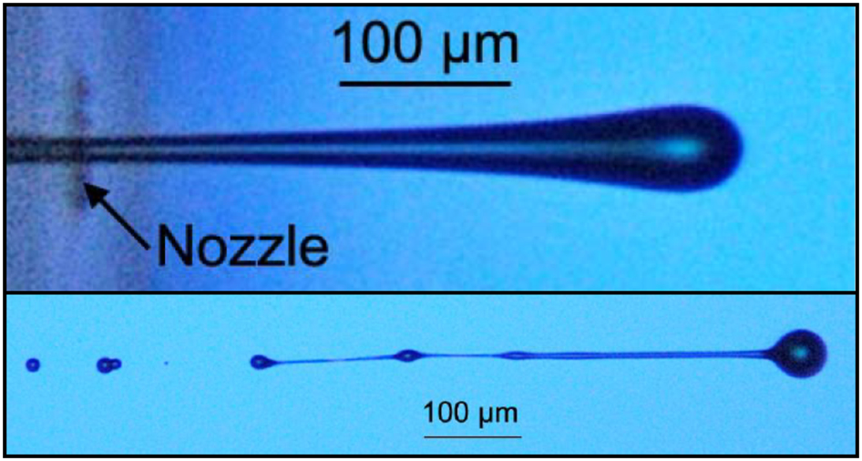
There are two further limits that must be considered in defining the properties of a printable fluid. Duineveld proposed a minimum drop velocity to overcome the surface tension at the aperture and there will also be a maximum drop velocity above which an impacting drop will splash on a flat substrate. These conditions can be conveniently illustrated in a parameter space defined by the Weber and Reynolds numbers and are shown in Fig. 3. 12
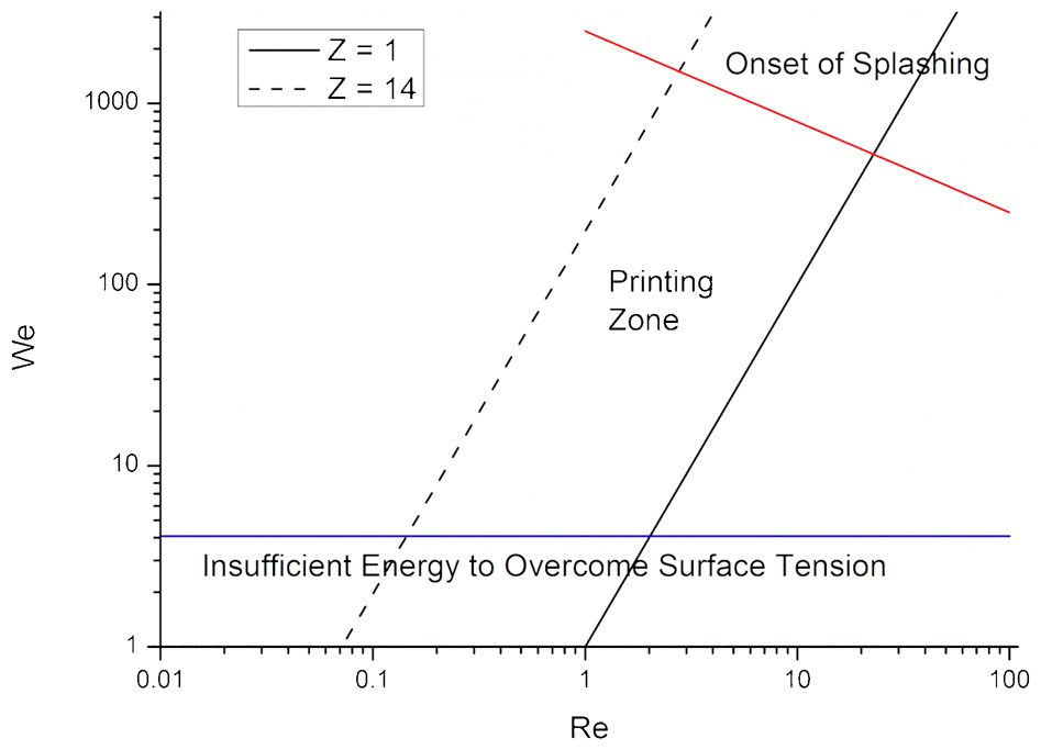
Although Fig. 3 presents a formal dimensionless analysis to determine whether a given fluid is printable, in practice the critical fluid parameter is normally the dynamic viscosity. This is because for most biological fluid the surface tension is in a relatively small range with its upper limit defined by that of pure water. The density of electrolytes and buffers does not deviate more than a few per cent from that of water. Hence the only physical parameter in equation (1) that shows significant variation between biological fluids is the viscosity. Past experience has indicated that a fluid viscosity of about 30 mPa s is a practical upper limit for printability. 12
The current generation of commercial DOD printers generates drops with the following range of properties:
drop volume, 1–100 pL
drop diameter, 10–60 μm
drop generation rate, up to 30 kHz
drop velocity at generation, 1–10 ms−1
distance from printer to substrate, 1–3 mm.
On impact with the substrate, the initial drop deformation occurs in a dynamic regime but after a few microseconds, viscous dissipation slows the process to the timescale where capillary forces dominate and the drop will subsequently spread to an equilibrium shape with the contact angle defined by the Young equation. For many applications in bioprinting, the desired pattern may be a series of discrete drops on a substrate; this structure is identical to that used in graphics printing where discrete image pixels are desired. However, when 3-D structures or continuous 2-D features are required, adjacent drops must overlap to form continuous features. When fabricating patterns or structures from materials for non-biological applications, the overlap can occur either through the contact of sequentially printed drops, which have not dried or solidified (wet-on-wet), or by sequential printing strategies that ensure individual drops are dry before any overlap (wet-on-dry). For many applications in tissue engineering and bioprinting in general, materials must remain in liquid form or else retain large quantities of water (e.g. hydrogels); in which case the most important deposition sequence will be wet-on-wet drop interaction. The interaction of sessile liquid drops on surfaces is controlled by surface tension forces and whether or not the contact line is pinned (Fig. 4), this imposes limits to the scale and stability of printed lines. 5,13–21
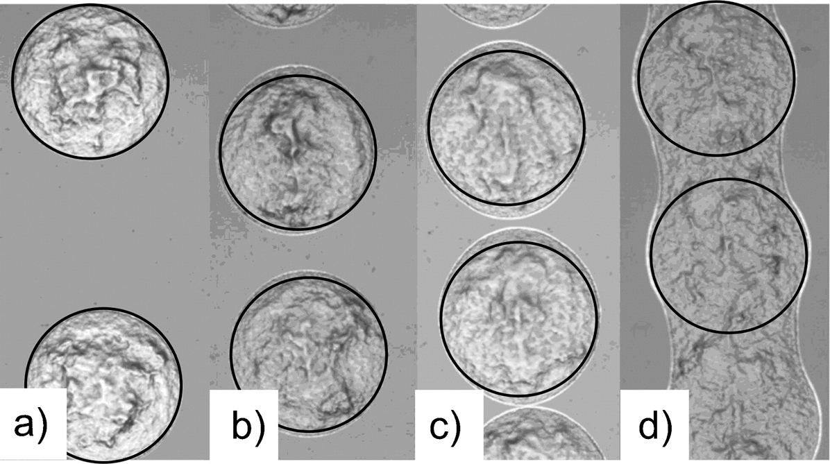
Inkjet-printed droplets of the organometallic ink on glass showing an interaction between neighbouring droplets with drop spacings of a p = 300 μm, b p = 195 μm, c p = 180 μm, and d p = 165 μm. The solid outline shows the position of the contact line with an identical isolated drop volume. In image d, drop coalescence has occurred even though isolated drops would not touch at that spacing. Reprinted with permission from Ref. 20. Copyright (2010) American Chemical Society
The next stage in the printing process depends on whether we wish the drop to dry or remain in a liquid state (e.g. if they contain cells in culture media). For many applications in sensor structures and scaffold fabrication, it is desirable that the drops dry or solidify to form a solid material. If solidification occurs by solvent loss there can be significant redistribution of solute during drying leading to non-uniform deposition of solute. Often this results in a characteristic ring deposit marking the initial contact line of a sessile drop. Such ring deposits are known as ‘coffee rings’ or ‘coffee stains’ and their presence was first explained by Deegan et al. 22 When a sessile drop dries the thin region close to the contact line loses solvent rapidly and solute precipitating here can pin the contact line preventing it retracting as fluid is lost by evaporation. This pinned contact line ensures that the region near the edge of the drop remains thin and loses solvent rapidly. Thus a concentration gradient is set up with relative solvent loss being much lower in the thicker regions near the sessile drop centre. Hence a fluid flow is generated from the centre of the drop to the contact line in order to maintain the contact line at its pinned position. This fluid flow transports fresh solution to the region of greatest precipitation rate, allowing further solute deposition. In the extreme, all deposition occurs in a ring close to the contact line and little deposition occurs in the drop centre. This is illustrated in Fig. 5, which shows both a top view of a coffee stained drop and the height difference between the deposited edge material and the centre. Coffee staining is a ubiquitous problem that has been observed in many applications of inkjet printing 6 and can be a barrier to many applications in sensors and arrays which must be stored in a dried state. The most promising route used in the literature to control coffee staining is to use mixtures of solvents with different vapour pressures. 23
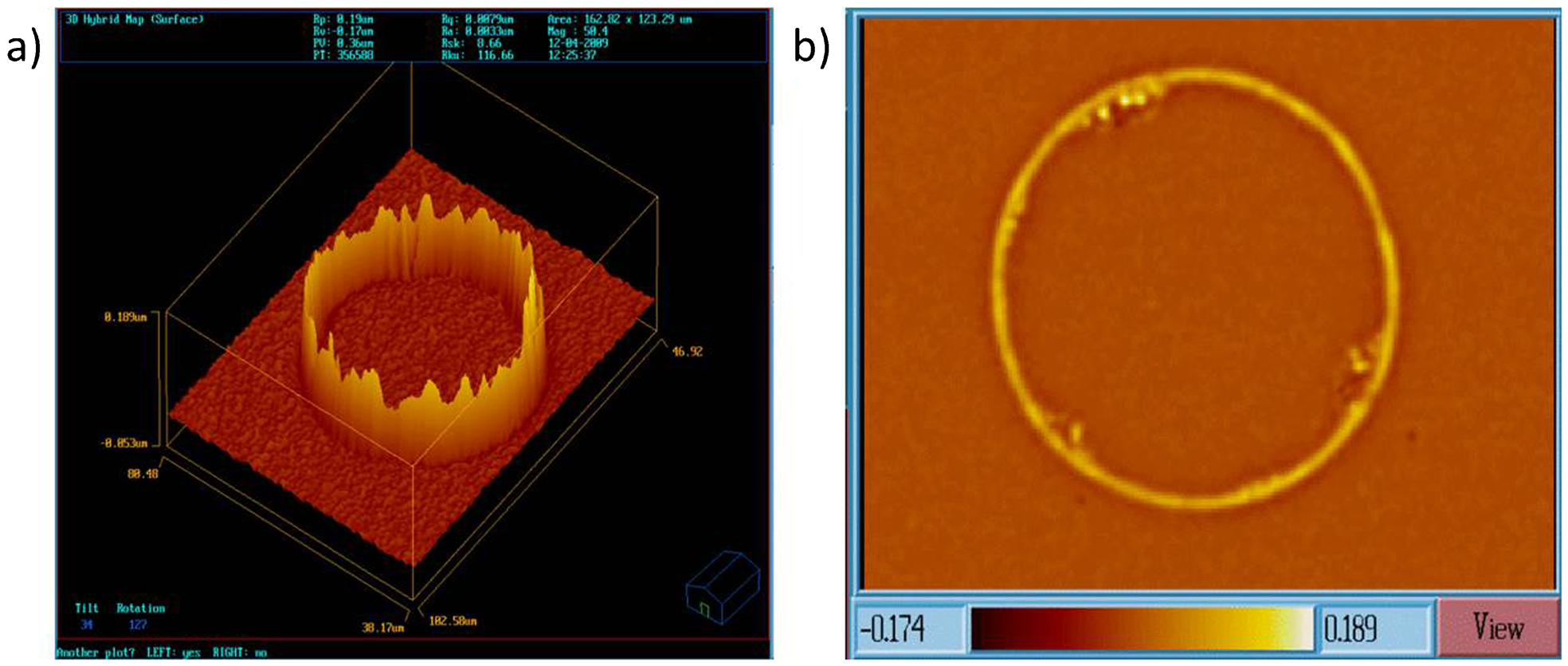
White light interferometer image of a drop exhibiting coffee staining. Material is deposited in a ring close to the contact line: a side view of a coffee stained drop and b top view of a coffee stained drop demonstrating the deposition of material at the contact line
The choice of solvent composition is a key factor in dictating the formation of coffee staining during the drying of printed droplets. de Gans et al. use solvent mixtures, to generate Marangoni flows through differential evaporation rates that oppose the coffee staining flow. 24 Fig. 6 demonstrates how the addition of acetophenone to a mixture of polystyrene in ethyl acetate can alter the drying pattern of the printed drop. The difference in evaporation rates results in a drop that remains domed in appearance and has a much smaller footprint than the printed drop without acetophenone. The smaller footprint yields an improved resolution and droplet height. However, for many applications in tissue engineering, the choice of solvents is severely constrained to water; thus strategies to control coffee ring formation that are biologically compatible still need to be explored and new strategies should be identified. One such approach is to suppress coffee staining through increasing the viscosity of the fluid by adding small quantities of soluble polymers [e.g. poly(ethylene glycol)] that are not believed to be cytotoxic at low concentrations. 25,26
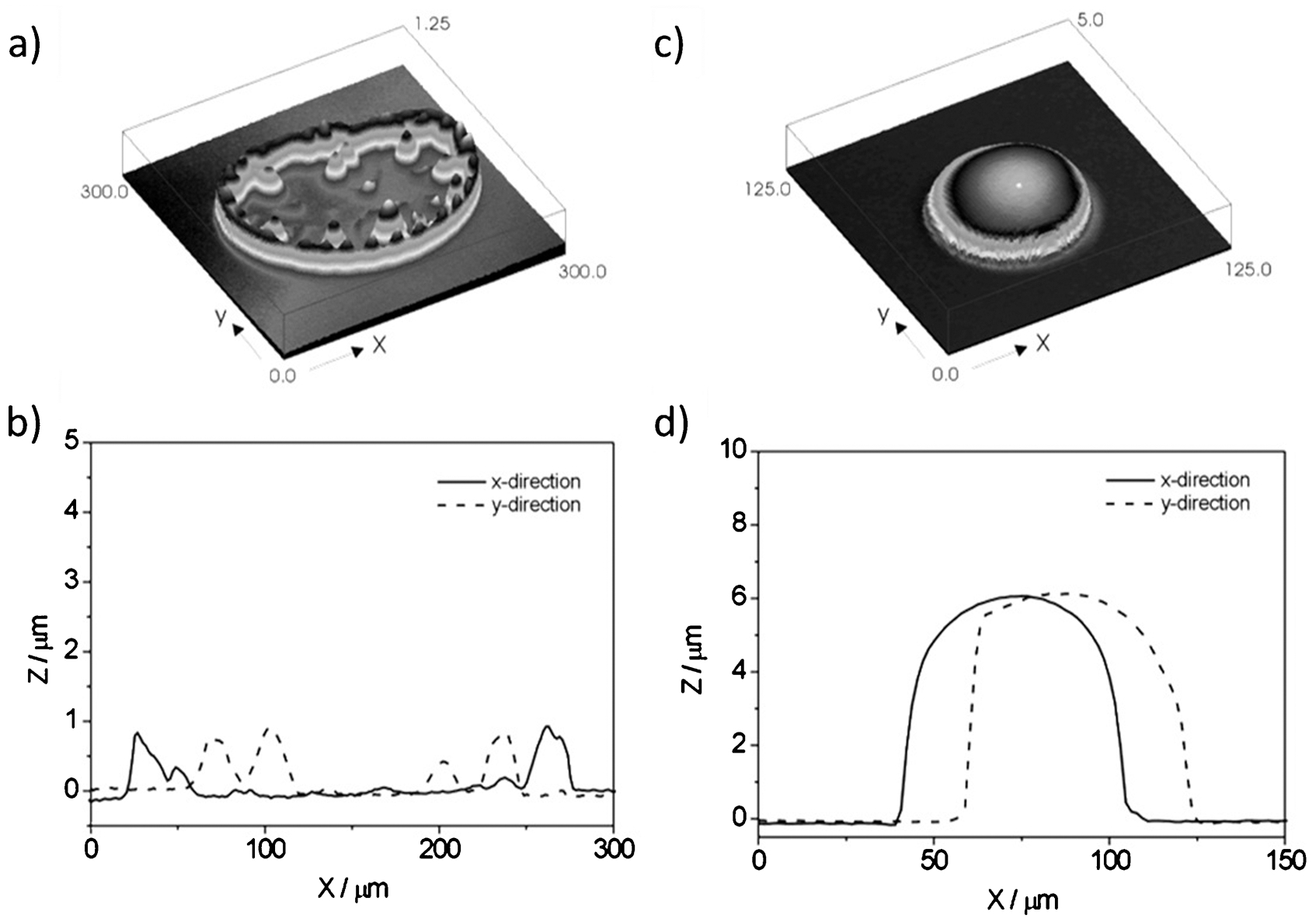
Printed drops demonstrating the effect of differential evaporation rates: a 1 wt-% solution of polystyrene in ethyl acetate on perfluorinated glass; b cross-section of a in the x- and y-directions; c 1 wt-% solution of polystyrene in an 80 : 20 wt-% ethyl acetate/acetophenone mixture on perfluorinated glass; d cross-section of c in the x- and y-directions. Reprinted with permission from Ref. 24
Any application of inkjet printing in the biological sciences must pay attention to the above limits to fluid properties and fluid/substrate interactions.
Proteins and biomacromolecules
The applications associated with protein deposition are primarily those geared towards analysis and can be divided into broad categories: paper-based biosensing and protein microarrays. Kodadek et al. proposed two further subcategories for protein microarrays based on function or detection. The difference lies in the order in which the bioreagents are deposited; proteins arrayed into a specific substrate location (protein function array) or specific ligands that interact with the protein of interest are patterned (protein detection array). 27
Protein arrays can be used to detect a required target in sera and to provide information regarding the molecular interactions of proteins advancing our knowledge in the field of proteomics. Likewise, an array of several proteins can be used in conjunction with cell culture to provide information as to the cues required for cell differentiation. 28 Protein arrays have been identified as a potential application for DOD inkjet technology. 29 Indeed there is at present at least one commercial inkjet printing system (Arrayjet; Roslin, Scotland, UK) that is specifically designed for biological array fabrication.
The manufacturing of low cost disposable biosensors is a developing area of commercial interest. The ability to provide accurate and portable testing on low cost polymer or paper substrates, for a variety of diseases and reagents, would be of benefit to general healthcare. 30,31 Typically a biosensor will consist of a target (what is being looked for) and a sample. However, such simplicity is hard to obtain with so few reagents directly available for the target of interest often necessitating several other reagents. Enzymes and other electrically active proteins can be patterned onto electrically conductive circuits forming biosensors to aid medical monitoring and diagnoses. 32
Several approaches to patterning proteins onto surfaces have been tried with screen printing and surface patterning using lithographic techniques being the most prevalent. Screen printing has been used for the manufacture of biosensors since 1980s with lithographic techniques offering a method of industrial scale fabrication for biosensors. 33 This has been followed by the use of lithographic techniques to achieve finer resolutions and smaller features in the final pattern (typically 1–5 μm). Inkjet printing offers a resolution lower than that of lithographic process (20–250 μm), however, it can offer several commercial advantages. Inkjet printing is a non-contact, mask-less, direct patterning tool. Small deposition (2–10 pL), with reduced contamination because of the non-contact nature of the technique combined with less processing steps and improved liquid management, promises a manufacturing technique that is flexible, low cost and amenable to scaling. 30,31,33 Delaney et al. identified a trend whereby proteins patterned through screen printing would be later followed by inkjet printing in an effort to reduce waste, costs and contamination. 30
Drop-on-demand printing can be distinguished through actuation mechanisms; thermal, electrostatic or piezoelectric. 6 Each actuation method has advantages and disadvantages and their impact on the retained activity of the printed biomolecules should be carefully considered. The printers and applications discussed in the following section have been summarised in Table 1.
Summary of printers and application for bioprinting. T: thermal, P: piezoelectric, E: electrostatic; D: direct fabrication, I: indirect fabrication
Thermal inkjet printing
Several research groups have shown that the thermal printing of biomolecules, such as DNA, horseradish peroxidase and glucose oxidase (GOD), has a minimal impact (up to 15% activity loss) on the final enzyme activity. 34,35,37
The prime concern of thermal printing is the high operating temperatures close to the thin film heating element which may reach 200–300°C. Setti et al. investigated the use of thermal printing for the deposition of β-galactosidase (GAL). The exposure time regarding the heat in a thermal printer is small with temperatures of 200–300°C achieved in 2 μs generating a shear stress of 10 ms−1. 34,35 Setti et al. reported the timescales for the bubble cycle (formation and collapse) and the subsequent fluid flow into the nozzle as 10 and 80–200 μs, respectively. The short cycle time between drop formation and the flash heating of the liquid is thought to lead to little heating of the fluid remote from the heater and thus a wide thermal gradient occurs within the fluid and this results in a negligible influence over the viability of the enzymes creating a wide thermal gradient within the bulk fluid (Fig. 7).
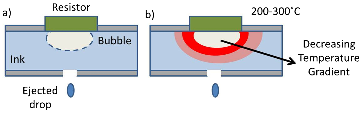
a Schematic of a thermal inkjet printer: The resistor superheats the fluid creating a bubble which expands expelling a drop; b a schematic of the temperature gradient in a thermal inkjet described by Setti et al., 35 the bulk fluid experiences lower temperatures than the fluid localised at the resistor
Setti et al. report a 15% activity loss with printed GAL which is attributed to the localisation of the actuation temperatures whereby fluid around the reservoir is flash heated with little effect to the overall bulk temperature. The modification of the ink with glycerol may also have contributed to the maintenance of the proteins activity by insulating the biomolecules from the thermal shock of actuation and increasing the stability of the jetted solution. 35 Glycerol has also been used to successfully modify a GOD solution. In both cases, the glycerol had no impact on the enzyme activity as compared to a control buffered sample. The outcome of the work by Setti et al. has resulted in a printed working glucose sensor demonstrating a minimum of 90% retained activity. 34 Khan et al. utilised a modified Canon desktop printer to deposit both alkaline phosphatase and horseradish peroxidase to create a patterned paper which retained its bioactivity (Fig. 8). The bioactivity level of the printed enzyme in this case is not quantified. 36,37
Magnified text printed using albumin-FITC on paper. Reprinted from Ref. 36. Copyright (2010), with permission from Elsevier
The literature on the effects of thermal printing on printed DNA and proteins is sparse and for the most part not directly comparable. A loss in enzyme activity, where reported, is attributed to the heat generated by the actuation though no analysis of the type or reversibility of the protein denaturation is undertaken.
Piezoelectric protein printing
Several groups have investigated the viability of piezoelectric DOD printing for the deposition of proteins. Unlike the thermal printers, extreme heat is not an issue, however, the protein ‘ink’ will still be subjected to high shear strain rates during the printing process. Okamoto found that the shear incurred in printing caused no damage to DNA, however, other studies have established a link between printing and loss of activity. 56 Nishioka et al. characterised the activity of horseradish peroxidase in relation to varied printer compression rates identifying a threshold of 2·5×104 μm−3 μs−1 below which no damage was observed. 38
In any DOD printer, the fluid experiences a strain close to 1 during drop formation, if drops form at a rate of 1 kHz (a typical drop generation rate), the fluid shear rate will be approximately 103 s−1. Further features characteristic of the inkjet process, such as tail elongation and droplet impact, splashing and spreading, all contribute similar strain rates which will lead to significant fluid stresses during the printing of biomolecules. 1,39 The fluid dynamics of a printed drop have been described by Feng et al. in which the Reynolds number is linked to the flowrate and actuation pulse. 57 A larger value of Re produces more unstable droplets with rounded droplets obtained as Re approaches 1. Cook et al. investigated a range of printing parameters including actuation voltage and pulse rise and fall times which demonstrated a 30% reduction in GOD activity using a commercial sugar based stabilising solution. 39 This activity decrease could not be attributed to a change in enzyme molecular weight or structure (both general and secondary) after printing. This may suggest a more subtle alteration of the protein structure induced by printing than can be identified by the light scattering techniques used. 39 Unlike Setti and Nishioka, no increase in enzyme activity over time was reported so it is unclear as to whether this damage is reversible or permanent. Mechanical stresses, both compressive and shear, exerted on the printed biomolecules originate with the pressure exerted by the actuator, the shear strain through the nozzle and also the impact on the final substrate and a variety of velocity gradients. 34,35,38,39 Therefore, with consideration of the forces on the biomolecule additives need to be selected to stabilise the biomolecular structure and cushion the influence of the drop generation and substrate impact forces. 38–40,58
As with commercial inks, ‘bioinks’ need to be formulated to meet the fluid property requirements of the chosen printer, while the influence of any additive, used to modify the physical properties of the ink, on the biomolecule of interest must be evaluated and understood. Printing parameters, where possible, also need to be optimised to achieve both jetting stability and performance with the maximum retained activity post-printing. As discussed earlier, the rheological properties of any ink are crucial to good printing performance. For graphics applications, a range of additives can be used to modify fluid characteristics, such as the viscosity and surface tension, enabling stable and reliable printing. However, with complex biomolecules, such as proteins, care must be taken to ensure that none of the additives interfere with either protein conformation or active sites.
In all forms of DOD printing, there is a concern that the propagation of a pressure wave through the fluid could lead to mechanical damage of the protein, in addition the small size of the drops and the high rate of drop generation lead to local strain rates in the range of 104–106 s−1. In piezoelectric inkjet printing, it is possible to vary the rate of actuation and explore how this influences damage to biomacromolecules; these studies found enzyme damage to increase with compression rate and also with actuation amplitude. 38,39 Similar issues of mechanical damage and life limitation of enzymes are a concern with all methods of dispensation. The addition of relatively small molecules, such as sugars and short chain polyalcohols, are known to stabilise protein suspensions. Nishioka et al. identified trehalose sugar as a protein stabiliser that can help to limit potential conformational changes caused by printing through hydrogen bonding. Glycerol is also a popular additive, which has the added benefit of increasing ink viscosity leading to a more stable jet. Glycerol modification of ink can improve droplet shape and printing performance (30–40% addition), however, as highlighted in Fig. 9, the addition of modifiers such as glycerol should be done with care to achieve the best compromise between printing stability and detrimental additive effects. 32,40,59
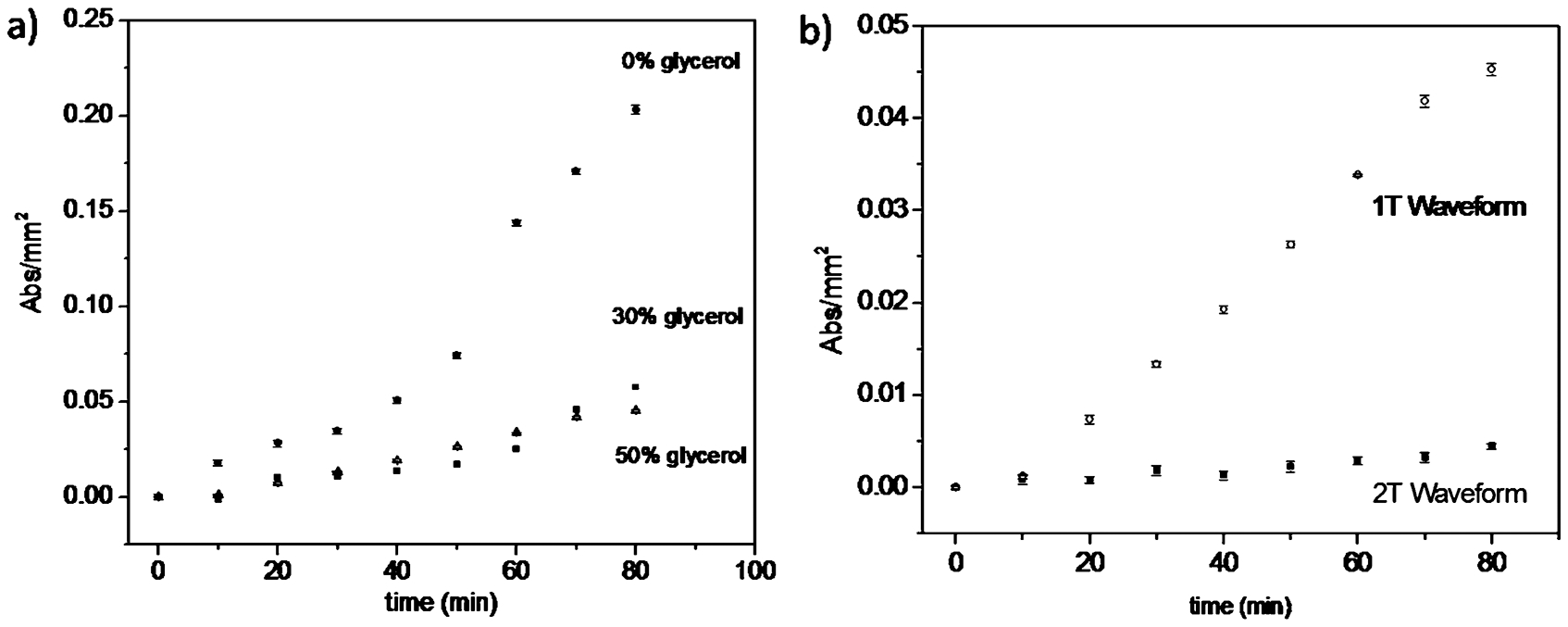
Glucose oxidase (GOD) activity in relation to glycerol content. Reprinted with permission from Ref. 40. Copyright (2009) American Chemical Society
Arrabito et al. found that piezoelectric DOD printing at higher voltages caused a delay in enzymatic activity suggesting that a reversible deformation occurred, proteins printed at 40 V showed activity but with a time delay of 60 min. The pulse duration also had an impact on protein activity with the longest pulse (23 μs) resulting in a significant decrease. 40 It is difficult to interpret these data without precise knowledge of the design of the inkjet printer fluid channel design. Reis et al. have shown that drop generation in a piezoelectric DOD printer is controlled by acoustic resonances within the fluid channels behind the printing aperture and the precise details of the actuation pulse control printing behaviour. Indeed it is known that the design of the actuating waveform used in commercial DOD printers is crucial in controlling performance and that the waveform must be tuned to each individual fluid. 7 Thus it is reasonable to expect that precise details of the actuating waveform may influence the behaviour of biomacromolecules after printing. It is worth noting that thermal DOD offers less control over the actuation pulse than is available to piezoelectric or electrostatic printing. As with printing cells, the printing parameters require careful study and optimisation to provide the minimum post-printing damage. 40,58
Allain et al. compared both commercially available piezoelectric and thermally actuated printers which were subsequently modified for bioprinting. 41 The modifications depended on the initial printer design and influenced factors such as the total sample volume required, e.g. the Epson piezoelectric printer required a higher operating volume and utilised the same cartridge resulting in contamination concerns. Allain et al. also determined that a thermal printer operated most reliably when high ethanol concentrations were added to the ink whereas the piezoelectric resulted in a poorer pattern but could utilise water based inks. 41 This research demonstrates the advantages and disadvantages of each printing method from a practical modification route. However, if bioprinting becomes a true clinical fabrication method then it will be necessary to collate and evaluate all quantified research to determine the optimum actuation mechanisms and printing parameters resulting in a custom build incorporating a suitable sterile environment.
Cell patterning
The first reported use of inkjet printing to position and pattern cells using printing and plotting technology was by Klebe 42 who used a thermal DOD printer to deposit patterns of fibronectin to control the local adhesive state of a substrate. During subsequent cell culture, cells selectively adhered to the patterned region of the substrate. Control of cell behaviour through local patterning has been developed further by a number of workers. Watanabe 60 successfully printed patterns of insulin related growth factors onto the substrates using a desktop thermal DOD printer and observed enhanced cell proliferation on the patterned regions. Roth et al. printed collagen suspensions to control local cell adhesion and achieved a spatial resolution of about 350 μm. Smooth muscle cells and neuronal cells were grown successfully on these patterned regions and their behaviour was observed, Fig. 10.
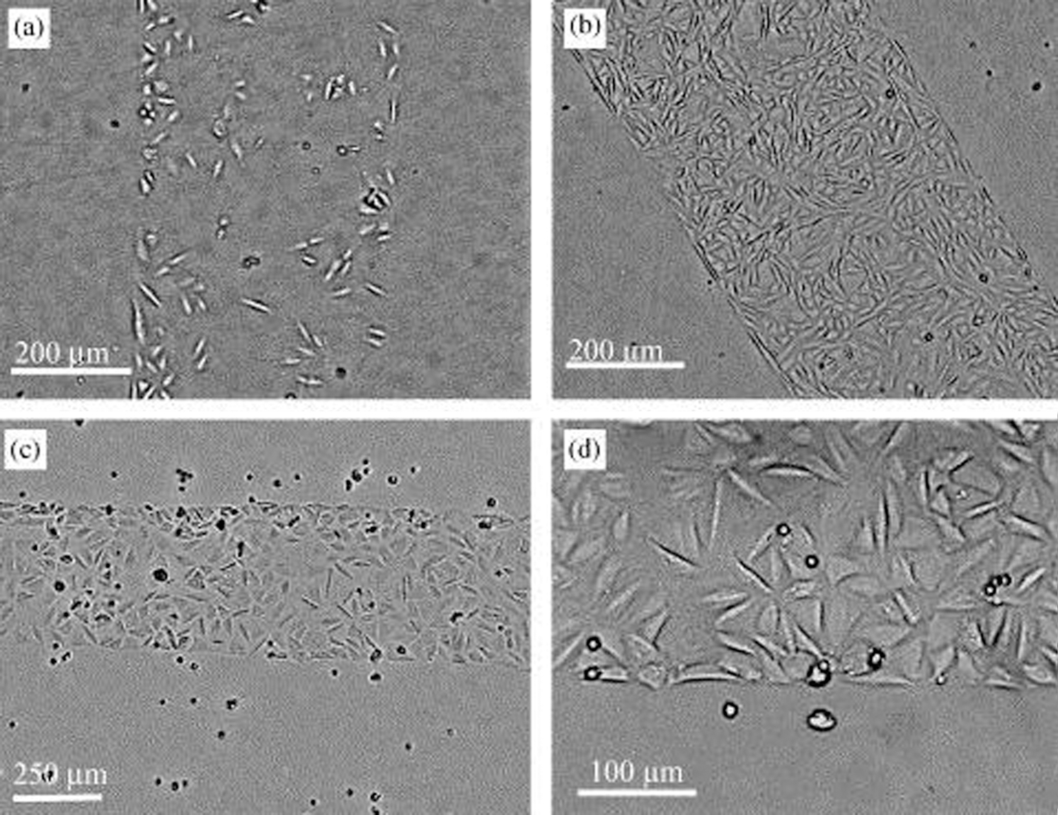
Light micrographs of a printed collagen line pattern seeded with SMCs after culture times of a 1 day, b 4 days, c and d a 500 μm wide line, 4 h after high-density seeding, but prior media rinse to remove unattached cells. 43 Reprinted from Ref. 43. © (2004), with permission from Elsevier
Sanjana et al. carried out similar experiments printing polylysine/collagen suspensions onto poly(ethylene glycol) coated slides to provide cell adhesive regions but using piezoelectric DOD printing. Neurons were cultured on these patterned substrates and electrophysiology experiments reported to show that their behaviour was similar to cells grown on unpatterned substrates. 44 Miller et al. extended this methodology through printing patterns of growth factors with varying amounts of surface concentration and demonstrating that the rate of cell proliferation depended on this concentration. 45 Gustavsson et al. used similar DOD technology to guide neurite growth along laminin patterns. 61 The latest developments of this technology have been used to control stem cell fate through the specific surface patterning of biochemicals. 62
Cell printing
An alternative route to cell patterning by the printing of adhesion or growth promoters is to directly position the cells in their desired location by printing. Drop-on-demand inkjet printing is particularly suited for this application because it can be used to selectively position cells in a drop of culture media. One advantage this method has over substrate patterning is that it is relatively easy to print heterogeneous structures with different cell types in different locations on a substrate. Many of the considerations that are important for the printing of functional biomolecules are also important for the printing of cells. In particular, it is important to consider whether the stresses induced by printing and substrate impact will damage or adversely affect cell behaviour. Second, the conditions of cell survival limit the range of fluid properties accessible and how the cells must be maintained in a hydrated condition after printing.
Following on from the work of Klebe, 42 Boland et al. looked at the selective deposition of cells and cell aggregates. This work initially used piezoelectric micropippetting valves mounted on an inkjet printer carriage rather than direct inkjet printing (Fig. 11). 46,63 This system used apertures >150 μm and thus the available resolution, which will be controlled by the contact angle of the resulting sessile drop, was considerably lower than that available from inkjet printing.
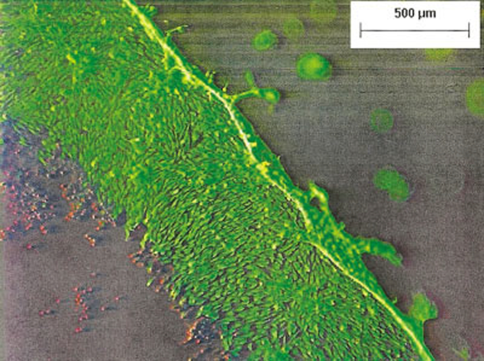
Cell aggregate fusion on a printed collagen gel ring. The image obtained on an epifluorescent microscope shows fused aggregates and cells that migrated across the gel. Cells that migrated towards the centre of the ring (in red) proved non-viable, possibly because they became dry outside the gel. 46 Copyright © 2003 Wiley-Liss, Inc.
Boland and co-workers subsequently investigated the viability of cells printed with a thermal DOD printer and found a viability rate of 80% after printing. This cell death cannot be attributed directly to the heat exposure as the printing medium of 3× Dulbecco's phosphate buffered saline solution (DPBS) contributed a 15% loss in viability demonstrated by the viability of the unprinted control. 64 The subsequent loss in viability because of the suspending media is detrimental to the overall procedure and has a significant impact when comparing viability results from this study with those using alternative actuation methods. The study acknowledged the effect of the hypertonic solution as a compromise between a decrease in cell size preventing nozzle clogging and overall cell viability. Subsequent work by Boland et al. utilised a 1× DPBS solution more commonly used in cell culture.
Cell viability after thermal DOD printing Chinese hamster ovary (CHO) cells was quantified in a more recent study using live-dead staining and assessed for multiple cell concentrations varying from 2 to 16m cells mL−1. 48 The average viability, regardless of cell concentration, is reported as 89%. Apoptosis studies demonstrated no significant difference between the numbers of apoptotic cells in printed and unprinted controls. The viscosity of the highly concentrated cell solutions is not reported in the literature. Cui et al. also report no adverse issues with the use of such highly concentrated cell suspensions such as increased cell sedimentation, aggregation or nozzle blockages during thermal printing. 48 This study looked at cell damage and reported the number of post-printing apoptotic cells as 3·5±1·3%, which was comparable to the un-printed control samples (3·2±1·6%). Evidence of transient membrane damage to the cells after printing was established with pores forming with an estimated diameter of 105 Å. 48 The transient nature of this membrane damage is assumed because of the long term survival of the cells and no time dependant study has been conducted.
Xu et al. investigated the transient pore damage after thermal printing as a means for transfecting cells with a success rate of 10% transfection and a higher viability (90%) as compared to electroporation where transfection was 70% successful but with a 60% cell death resulting in a 32% yield of transfected cells. It is suggested that the low transfection rate of the printer is because of a low energy pulse, originally employed to maximise cell viability resulting in pores, which may be too small to allow for bulk transfection. An increase in the power of the applied pulse could result in a higher transfection rate although the overall cell viability may be compromised. 48,49
Cui et al. have utilised thermal printing to directly deposit mouse myoblasts onto a silicon based cantilever biosensor device. They demonstrated aligned myotube formation along the printed substrate which outperformed the control samples. The lack of information regarding the preparation of the control sample hinders the conclusion that the bioprinting offers any additional benefits other than precise cell seeding. The experimental states that the control was prepared in a Petri dish and the printed samples were transferred to a low attachment wellplate. This could be seen as a minor difference but if the initial cell attachment is compromised then the resulting lack of cell density would impact on cell alignment and myotube formation. Cui et al. have, however, shown that the precise placement of cells onto sensors is viable leading to a functioning biological micro-mechanical device that shows some potential for re-use. 50
The main concern with thermal printing cells is the temperatures involved and a possible concern regarding piezoelectric printing lies in its similarity with sonication. Piezoelectrics running at high frequencies, 15–20 kHz, can result in sonication of the cells leading to cell death. 65 However, most printing studies using piezoelectric DOD printers use a lower frequency range of 8–10 kHz and much lower power densities than in sonicators. Following initial cell viability observations, Saunders et al. conducted a statistical study on the post-printing viability of mammalian cells with regards to the influence of the waveform parameters. 51,52,66 The average viability of HT1080 fibrosarcoma, human osteoblasts and bovine chondrocytes post-printing is reported as greater than 95%. 52,67 Saunders et al. used a near square wave for the application of the pulse voltage allowing for additional parameters such as the voltage used (pulse amplitude) and the rise and fall times to be altered. An increase in pulse amplitude combined with a short rise/fall time generates harsher shear conditions in the fluid than those with lower amplitudes and longer rise and fall times. In this way, the effect of printing parameters on cell viability could be assessed. Saunders et al. showed that the pulse amplitude has a significant effect on cell survival with more cell death observed at 80 V than 40 V. However, despite the harsher conditions the cell viability remained above 95%. Although no studies have been done to investigate the possibility of cell membrane damage or induced apoptosis, the results reported by Saunders et al. show a higher viability than that reported for thermal printing studies 52,64
Nakamura et al. have demonstrated some success in using electrostatic DOD printing with a number of cell types; human umbilical vein endothelial cells (HUVECs), human cervical carcinoma cell line (HeLa) and bovine vascular endothelial cells. 53,55,68,69 Nakamura et al. observed cell attachment post-printing. However, there is no quantitative analysis of cell survival in the literature for the electrostatically actuated printing. Despite this lack of direct evidence, the fluid mechanical environment of the ink during electrostatic printing is expected to be very similar to that experienced during piezoelectric inkjet printing because both printing methods actuate the fluid through direct wall displacement, hence the authors anticipate the data in the literature for piezoelectric printing indicate that electrostatic printing should be equally successful.
Careful choice and consideration must be given to the application of a cell printed structure. The resolution of an inkjet printed pattern is determined by the spread of the printed drop on the surface, which is in turn controlled by the equilibrium contact angle. 9 Typical drop volumes are in the range 1–100 pL and the resulting contact radius of the drop is in the range of 10–100 μm. Thus, if inkjet printing is to be used to deposit a single cell, the footprint of an individual drop is larger than that of an adhered cell. Single cell deposition is achievable as shown in Fig. 12. This image was obtained printing bovine chondrocytes at a concentration of 1×10⁶ cells mL−1 using a 60 μm microfab nozzle (piezoelectric). Analysis of the printed chondrocytes showed that the number of cells per drop conformed to a Poisson distribution indicating that cell deposition was random. This can be influenced by external factors including cell concentration, sedimentation, droplet size, and cell aggregation. These factors impact on all cell patterning applications from precision cell placement to the printing of a defined area.
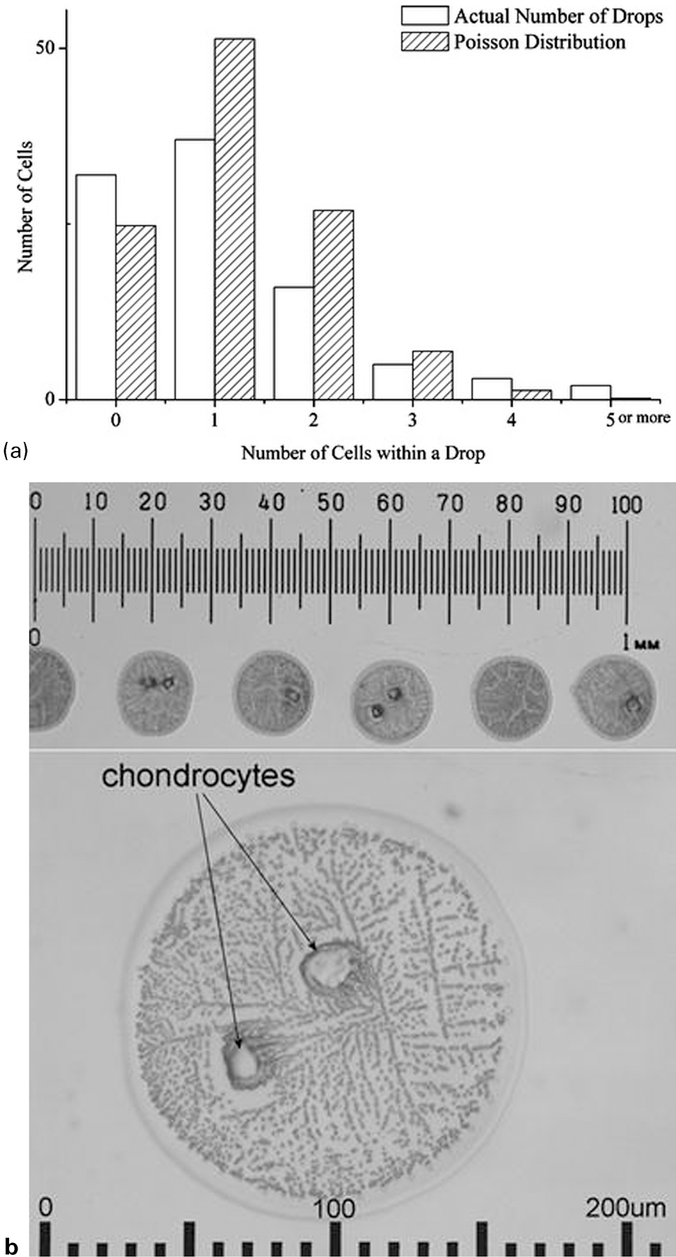
a Frequency analysis of the distribution of cells per drop in a series of isolated printed cell suspensions: data from 95 printed drops of a chondrocyte suspension. b Isolated drops of chondrocyte suspension printed for cell distribution statistical analysis. Lower image is of a dried drop showing precipitation from the media around two cells. Original copyright notice is given to the publication of Figs. 3 and 4 in Ref. 67
To generate a reliable and reproducible patterning method, it is necessary for the inkjet design to evolve alongside an increased understanding of the printing dynamics. Figure 13 highlights a selection of areas where further research and printer development is required. Characterisation is a recurrent and important theme and the research field would benefit from information arising from the standardised analysis of cell damage and attachment as well as the more logistical issues of sedimentation, cell distribution and cell/drop delivery. Current literature represents snapshot data of successful cell and protein printing across a multitude of printer types which makes a specific comparison and therefore, a subsequently informed choice as to the best printer for a particular application difficult.
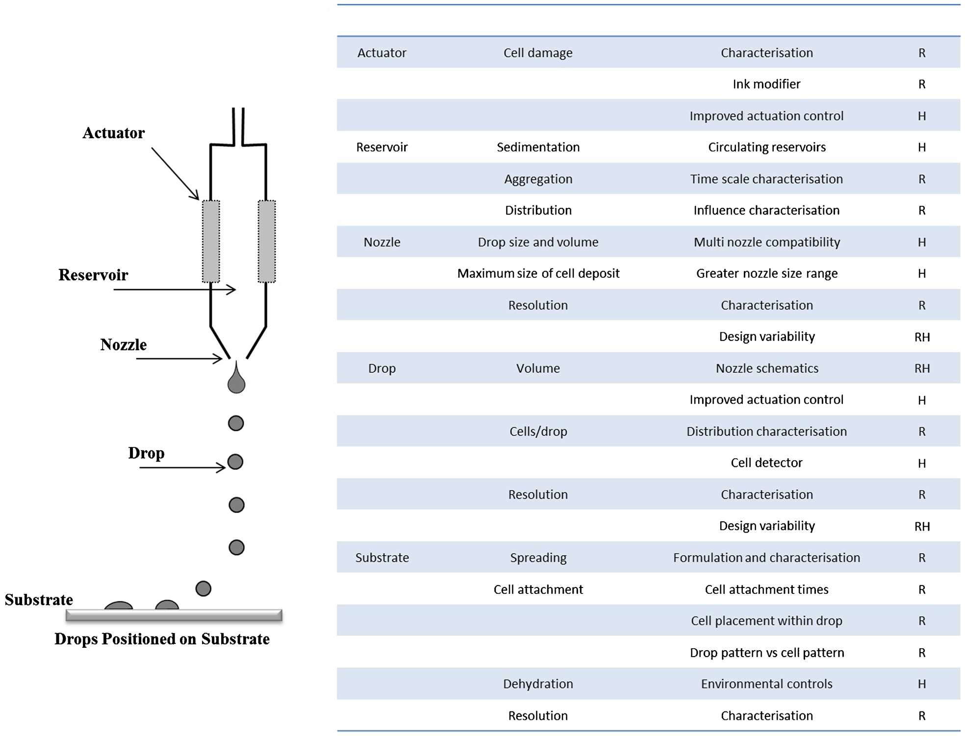
Schematic of a printing assembly with associated hurdles for advancement. R indicates an area where future research is required; H indicates where hardware improvements could be accommodated
Technological advances could aid in single cell delivery if it were possible to develop a detection mechanism, such as that used in flow cytometry, to identify when a cell has been deposited and tie this into the actuation control. This technology could then be utilised to tailor the number of cells delivered to a specific spot if issues such as cell aggregation and distribution within the reservoir were also controlled to yield one cell per drop.
Scaffold printing
Traditional techniques for tissue engineering seed cells onto material scaffolds post-fabrication. Cell seeding in this manner is non-uniform and often fails to penetrate into the scaffold centre. Tissue engineered constructs require a scaffold to provide support, stability and mechanical cues to the cells. Scaffolds can be fabricated to be inert or have a direct effect on cell response. Rapid prototyping techniques can fabricate scaffolds with increasing design complexity to either mimic natural structures or confer a specific architecture. The intricacies of the tissue engineering scaffold, however, are irrelevant if efficient cell seeding cannot be attained. These rapid prototyping techniques such as bioplotting and inkjet printing are moving towards hybrid scaffolds whereby cells are deposited alongside or within the scaffold material. Inkjet printing already accommodates the use of multiple colours and the exchange of coloured ink for materials, including biologicals; offers a multi-deposition technology, which has yet to be fully exploited. In order for inkjet printing to be a profitable means of fabricating a tissue engineering scaffold either directly or indirectly, the material selection is critical. The criterion for materials selection is complex and is outlined as follows.
Printability and substrate interactions
The scaffold material must initially be a printable liquid and therefore comply with the fluid physical property requirements of the printer. These parameters were discussed earlier in terms of fluid density, viscosity and surface tension. Typical graphics printing inks for use in DOD printers have viscosity values in the range 3–30 mPa s, and surface tension 20–70 mJ m−2 and density close to 1000 kg m−3. In addition to this, printability is found to be strongly influenced by the presence of polymers in solution. 70,71 Thus the use of Newtonian fluid characteristics in determining whether a particular ink is printable acts as a lower bound guide.
The main points of material selection for printing have already been previously discussed. Tissue engineering applications demand the printing of connected patterns rather than the discrete drops utilised both in the traditional graphics arts applications and the dosing of biosensors. This necessitates the interaction and coalescence of drops on the surface; hence an important issue is the stability liquid lines or sheets formed by the interaction of adjacent drops spread on a surface. Given that single drops of fluid spread to a radially symmetrical sessile configuration to minimise surface energy, all surface features constructed from fluid drops would be expected to be unstable and reshape to minimise surface energy. However, the behaviour of moving liquid drops is controlled by dynamic processes and thus metastable shapes and states may exist.
The interaction of a liquid drop on a substrate is often characterised by the equilibrium contact angle, θeqm, which for an equilibrium sessile drop can be described by Young's equation
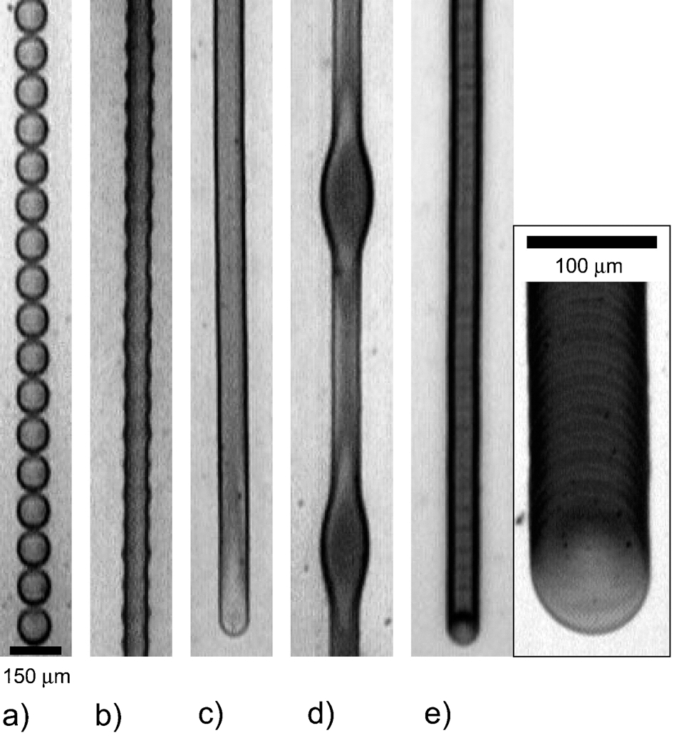
Examples of principal printed line behaviours: a individual drops; b scalloped; c uniform; d bulging and; e stacked coins. Drop spacing decreases from left to right. Reprinted with permission from Ref. 19. Copyright (2008) American Chemical Society
Phase change
The matrix materials must undergo a controlled phase change after printing to ensure stability. In order to produce 3-D objects, second and subsequent layers are printed on top of the solidified prior layer. The phase change should ideally be triggered on demand to allow for the printed drop to reach the substrate and be gelled in situ without interfering with the printhead. Gelation inside the printhead creates blockages resulting in a failure to print. Gelation can be through loss of a solvent by evaporation, an environmental change such as temperature and pH or through the addition of a chemical cross-linker. If the target is simply the fabrication of a 2- or 3-D structure containing no biological species, there are many routes through which the phase change can occur. Indeed it is possible to produce a mould by inkjet printing using solidification from the molten state at temperatures incompatible with biology and then utilise the mould to fabricate a scaffold from a biological material. 74 Fig. 15 demonstrates the artificial vasculature fabrication by Sachlos et al. This indirect fabrication route utilised printing to create a sacrificial mould which was then cast with collagen. Nonetheless, one of the attractions of inkjet printing scaffolds directly is the possibility of seeding the scaffold with controlled cell numbers and placement as part of the fabrication process, in which case the phase change must be cyto- and biocompatible.
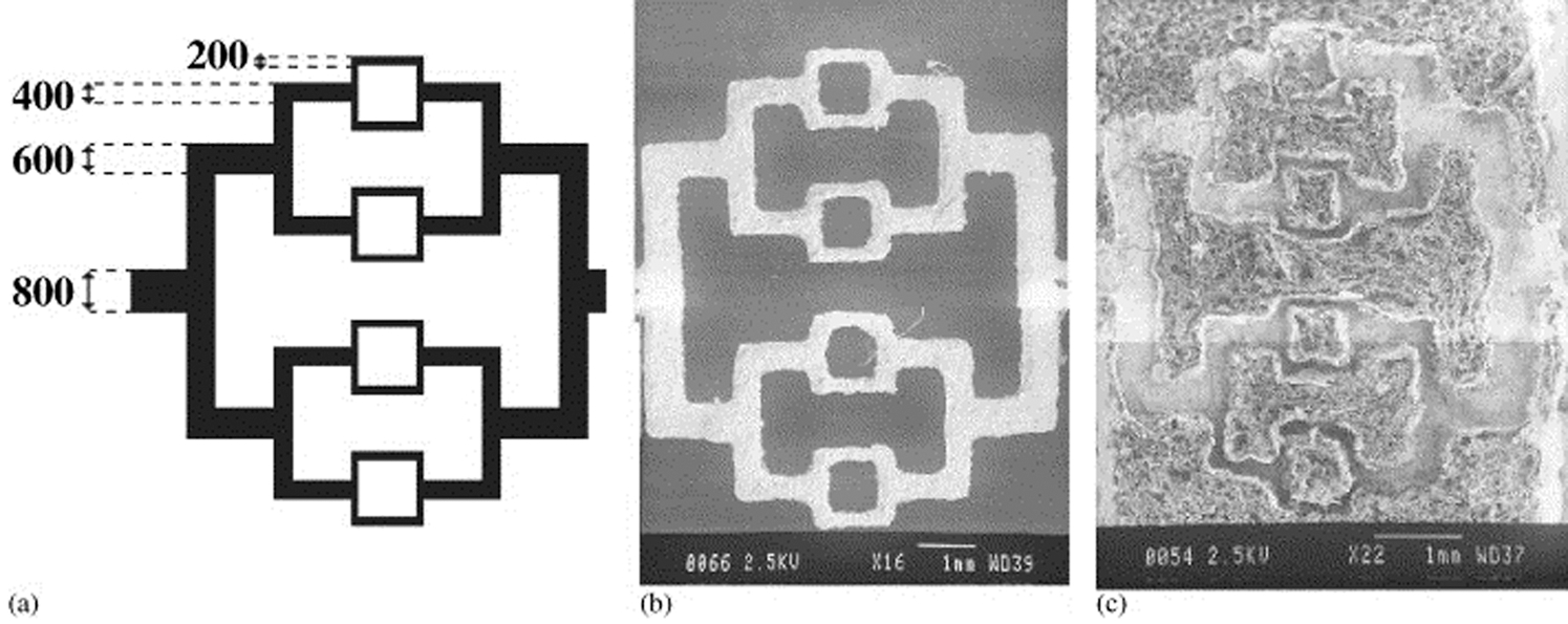
Artificial vasculature created by a designing the CAD model to possess a series of branched shafts with decreasing dimensions (dimensions are in micrometres), b SEM image of the printed mould; the shafts designed to be 200 μm are approximately 220 μm, c SEM image showing collagen scaffold with predefined internal channels. The smallest channels in the collagen scaffold are approximately 135 μm. Reprinted from Ref. 74. Copyright (2003), with permission from Elsevier 6
Biocompatibility
The matrix material acts both as a carrier fluid, when in liquid form, and as a scaffold once solidified. It therefore needs to be non-toxic and compatible with the cells and biological materials. Solidification of the matrix material should not incur cell death and provide a suitable environment for cell encapsulation or adhesion (according to the application). The gelled/solidified matrix should be sufficiently stable to allow cell adhesion and withstand standard cell culture conditions for a sufficient time period enabling the cells to adhere and produce extracellular matrix. Degradation products should be non-toxic and ultimately have a natural elimination or excretion pathway. Tailoring the initial fluid formulation to meet both the biocompatibility requirements and the previously discussed fluid criteria is challenging. The materials and gelation mechanisms discussed in the following section are summarised in Table 2.
Summary of materials and gelation mechanisms T: thermal, P: piezoelectric, E: electrostatic; D: direct fabrication, I: indirect fabrication
Gel printing
Boland et al. demonstrated that thermoreversible gels such as poly[N-isopropylacrylamide-co-2-(N,N-dimethylamino)-ethyl acrylate] could be deposited with cell aggregates to form a layered structure. 46 Reversible gelation can be useful for the initial fabrication of a scaffold, however, secondary methods would need to be addressed to maintain the scaffold structure in the absence of a trigger. An example of this would be a thermoreversible gelation followed by a chemical or photopolymerisation reaction. 80
Photopolymerisation has provided a route for generating stable hydrogel structures for tissue engineering. Three essential components for photopolymerisation are a monomer, photoinitiator and a light source. UV light can be damaging to cells, so photoinitiators can be carefully chosen to operate in the visible light or near UV spectrum. The toxicity of the monomers used will also have an impact as for injectable polymers or applications involving cell encapsulation, the cells are initially suspended in the monomer/photoinitiator solution before polymerisation. There is also potential for the un-reacted monomer to leach from the polymerised gel. Component toxicity has a greater role in printed systems when considered alongside the findings of Xu et al. discussed earlier. 49 Transient damage of the cell membrane during thermal printing may be reversible but it increases the exposure of the cells to toxicity. De Groot et al. proposed that incorporation of photoinitiators into the polymer could ensure maximum polymerisation. 86
Elisseeff et al. focused on the formulation of an injectable polymer that can be photopolymerised in situ through the skin using the photoinitiator 1-hydroxycylcohexyl phenyl ketone (HPK), which operates in the visible light spectrum. Low initiator concentrations were found to be sufficient for polymerisation without causing cell damage. Increasing the initiator concentrations above 0·04 wt-% resulted in decreasing cell metabolism. 81,82 Pilkenton et al. found that the atmospheric oxygen absorbed by HDDA during printing hindered the curing of the films leading to a need for an inert gas to be flowed across. 83 This work highlights the need to take into consideration not only the materials used and the reaction process but also the surrounding printing atmosphere and its control. The main types of scaffold gelation and some of their considerations are discussed in this section and summarised in Fig. 16.
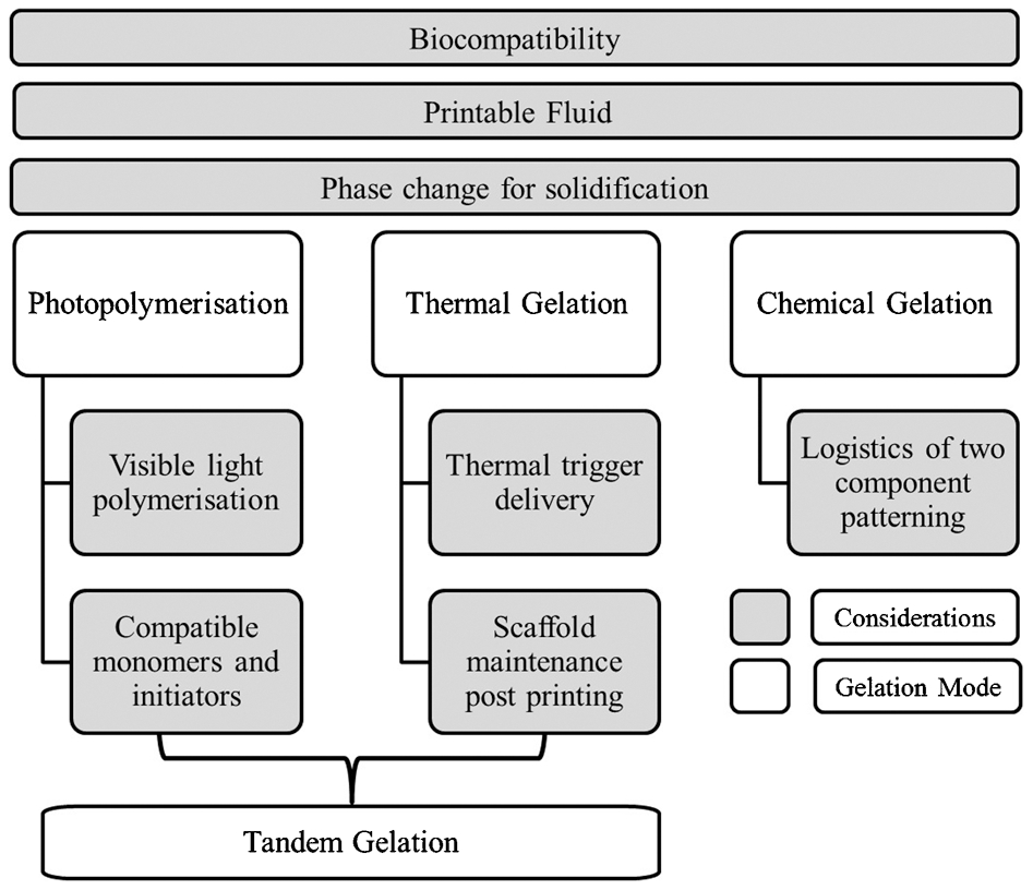
Image highlighting gelation modes and their main considerations
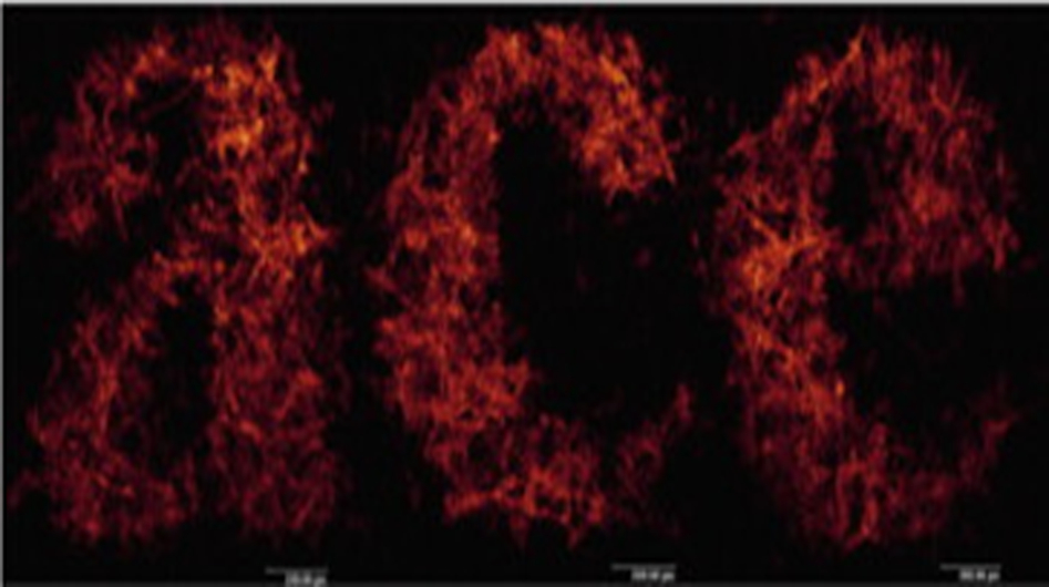
The use of photopolymerisation for inkjet printing has been briefly explored and is usually approached as a tandem gelation technique. Tandem gelation employs dual gelation to create a stable gel with controllable characteristics in the fluid state. An example of tandem gelation is where photopolymerisation follows a previous physical gelation, which is often reversible such as a thermoresponse. Cellessi et al. developed a hydrogel to exploit the cell encapsulation technology associated with the physical gelation mechanisms of alginate. The pluronic-based gel showed negligible cytotoxicity and gelled through a physical temperature change, which was followed by chemical gelation. 84,85 Di Biase et al. further explored the use of the polymer developed by Cellessi et al. with regards to printing. The thermoreversible Pluronic F127 gel was tailored to fit the printing criteria while containing sufficient material to form a photosensitive gel. 79,80 The viscosity was affected both by the concentration of the pluronic and the solution temperature resulting in a printable fluid at 5°C which gelled on contact with a room temperature substrate. The 3-D gel was then exposed to visible light (460 nm) to initiate the polymerisation reaction yielding a stable multi-layered construct. 80 Di Biase used this method to create a layered grid structure (Fig. 17), which demonstrated enough stability to survive liquid immersion. The main application of this work was intended as a construct for analysing cells and cells were not included in the printed layers but printed onto the layers following polymerisation
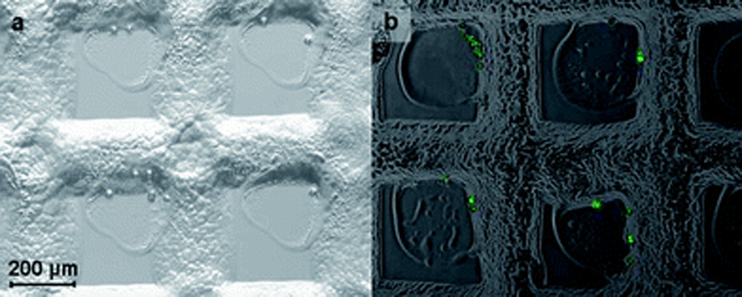
Multi-chamber patterns printed on a 500×500 μm grid, photocured and subsequently cell-seeded by inkjet printing, showing the presence of printed droplets contained by the scaffold walls using a optical microscopy and b fluorescent and optical microscopy 80 . Reproduced with permission of The Royal Society of Chemistry
Cui et al. report printing chondrocytes directly into a cartilage defect. 78 This is where the printing application is focused on demonstrating the ability to spatially position cells without the hindrance of three dimensions. Although Cui et al. polymerised the layers as they were printed it is unclear as to what role the defect plays in the gross shape maintenance of the final printed gel. The use of a poly(ethylene glycol) dimethacrylate (PEGDMA) gel provides a stable gel known to be compatible with chondrocyte cells with the benefits of photopolymerisation to provide stability. The study demonstrated the feasibility of depositing cells in a controlled manner to mimic the zonal layers present in cartilage tissue. It could be argued that the osteochondral defect acts as a mould with the printing technique supplying a more precise casting option, however, it is an important step towards rapid prototyping hybrid scaffolds aim to provide precisely positioned cells combined with a designed 3-D matrix. It would be interesting to see how the simultaneous polymerisation of layers fare outside of the osteochondral defect environment as an example of a directly fabricated hybrid scaffold free structure.
Logistical challenges
There are several approaches to gel printing, which are represented in the literature through the use of sodium (Na) alginate. Na alginate is a good example of the logistical challenges of utilising chemical cross-linking polymers as the printed scaffold matrix. Sodium alginate is a polysaccharide, which can be cross-linked through the replacement of the single charge Na ion with doubly charged calcium ions. How the calcium ions are provided is a key logistical step in the fabrication of a chemically cross-linked gel. A single layer printed alginate pattern has no mechanical or chemical adhesion to the glass substrate, therefore, if the cross-linker is added in bulk after printing the alginate drops will be washed away. A solution to this may be to use a drop on drop delivery mechanism whereby a pattern of the gel material is printed and then a cross-linker is printed on top of that pattern. This would need the use of two printheads working together with precision. The nature of the layered approach where an alginate drop is printed onto a cross-linker drop might yield gelled structures that are not fully bonded. The secondary gelation pattern would also have to be printed while the previous printed drops were still hydrated and the total deposition volumes optimised to prevent spreading and loss of resolution.
Printing into a liquid does offer a way around the hydration issues and is employed by two of the main printing research groups. The principle of this approach is where one material is printed onto a movable stage, which can be lowered down into the liquid as the scaffold gains height. Boland et al. print calcium chloride into a container filled with an alginate solution. The printing of calcium chloride into an alginate solution offers an easy method of fabrication as the viscosity of the alginate solution is not an issue. However, the diffusion of the calcium chloride ions deposited in this manner yields a porous structure with poor mechanical properties (Fig. 18a ). Once deposited the calcium ions diffuse out of the drop into the surrounding alginate creating a gelled structure containing voids of calcium depleted liquid. The voids are in the order of 25 μm in size and results in a scaffold structure which is mechanically weaker than that of a conventionally mixed alginate gel. 75
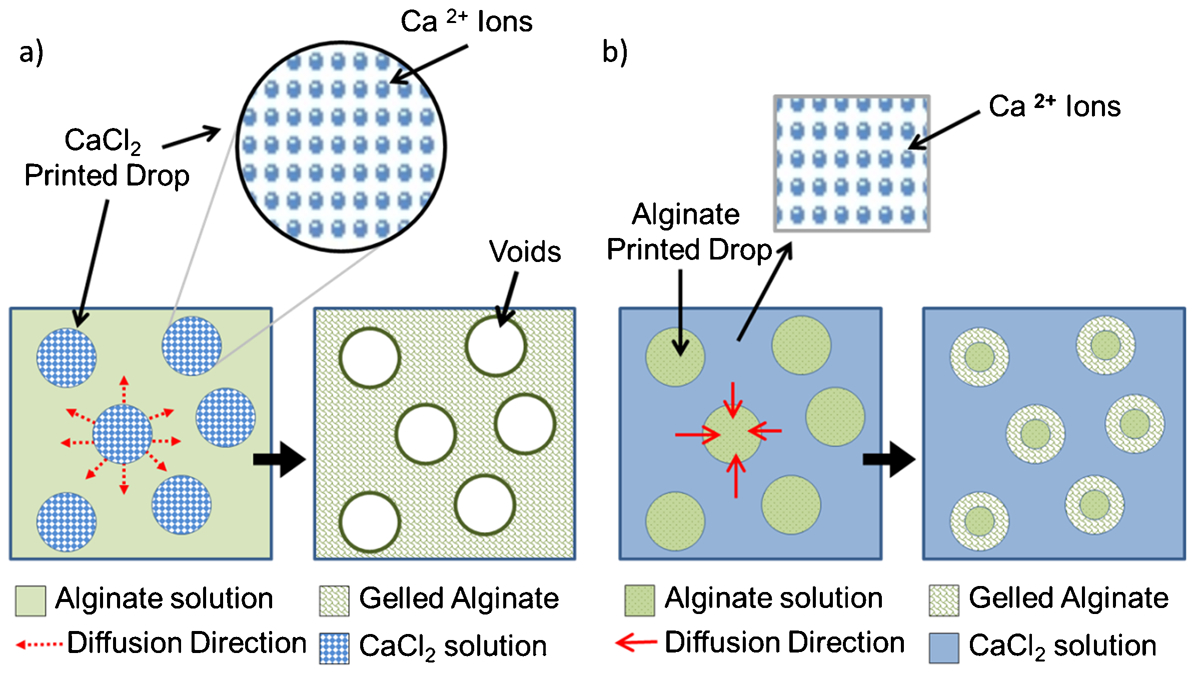
Schematic showing a calcium chloride solution printed into an alginate solution The calcium ion diffuse out from the drop leaving voids of calcium depleted liquid; b alginate solution printed into a calcium chloride solution. The calcium ions diffuse into the drop leaving a gelled shell with a region of un-gelled alginate at the centre
This approach has also been used with a collagen–alginate solution to generate a heterogeneous structure containing three different cell types. 76 Xu et al. printed bovine aortic endothelial cells (bECs), human amniotic fluid derived stem cells (hAFSCs) and smooth muscle cells (dSMCs) in a pie shape Fig. 19. The cells maintained their viability and phenotype following printing. Figure 19c shows the void structure formed during the gelation process with cells localised along the void borders.
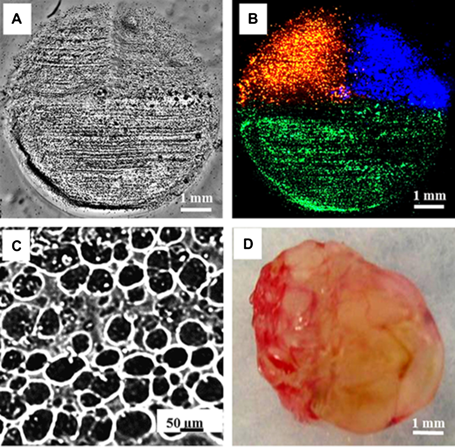
Light a and fluorescence b microscopic top views of a complete 3D multi-cell ‘pie’ construct before implantation. bECs (green), hAFSCs (blue) and dSMCs (red). Different cells were located on their predetermined locations after printing. c Microscopic image of the microstructure of the printed ‘pie’ scaffold. d Gross view of the retrieved ‘pie’ 2 week post-implantation. Reprinted from Ref. 76. Copyright (2013), with permission from Elsevier
The second approach is the reverse where an alginate solution is printed into calcium chloride. 68 In this case, the drop is gelled from the outside as shown in Fig. 18b . This means that calcium ions may not diffuse right into the centre of the drop once gelation has begun on the outside resulting in a variation of gel strength throughout the structure. Figure 20 demonstrates the structure of a hypothetical alginate bead where the calcium ions are introduced from the surrounding solution. The calcium ions gel the outer edge of the bead first and then diffuse in towards the centre. The exterior wall has ready access to calcium ions resulting in the formation of a superficial crust and concentric zones of varying gel strength the core of which is the least gelled. Smidsrod et al. predicted that the bead will contain discrete cavities, fractures and shafts. 87,88
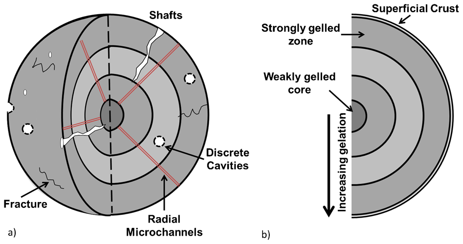
Schematic showing the hypothetical structure of an alginate bead gelled from the outside a 3-D schematic illustrating defect types and b a zonal representation of the gelation. Calcium ions gel the exterior of the drop first and then diffuse slowly through to the centre resulting in layers of varying gelation 87–89
Nakamura et al. have successfully printed alginate into calcium chloride to yield beads that can encapsulate cells reporting no gelation difficulties. Complete gelation of the beads is possible because of the small drop size (the beads are reported to be within the range of 20–40 μm 54,68 ) in relation to the calcium ions available. It would be expected that a superficial crust will form and that a gradient of gel strength will be present throughout the structure which could be attributed solely to the calcium exposure time. The concentration of the alginate is limited by the surface tensions and the viscosity requirements of the printer. Concentrations of up to 1% have been printed using the mechanically actuated printers. While both these methods overcome the initial obstacle of sample hydration there are compromises to be made throughout with regards to the mechanical properties, gel structure and the strength of the final construct, which are dictated by the diffusion mechanisms of the calcium ions and the printing limitations on the alginate concentrations which can be used. Both techniques result in the gelation of the printed matrix and maintain sample hydration; however, it limits the potential of combining a chemical cross-linker with another gel with a different trigger mechanism and also has an impact on the final gelled structure.
Pataky et al. found that blending collagen and alginate to form a bioink provided the stability of fast alginate gelation and the cell adhesive properties of the collagen. The alginate–collagen blend was printed, using a piezoelectrically driven microdrop system, onto a calcium loaded surface which gelled the alginate and held the collagen in place until its slower thermal-based gelation was completed. The alginate was then removed like a sacrificial scaffold to leave a collagen scaffold behind. Pataky et al. report that the scaffold resolution is affected and can therefore be primarily controlled through the surface interaction of the alginate as the spreading speed was far greater than that of the gelation. 77
Alginate is a good test material for the optimisation of gelation systems, however, as it has no RGD binding sites, cells find it hard to remodel, degrade and attach to this gel. As such alternative gels need to be chosen for any applications, which require the cells to have more freedom and adhesion beyond simple encapsulation. Such gels could be fibrin/fibrinogen or any other suitable chemically gelled substrate.
Conclusion
The literature has demonstrated that a wide variety of cells both human being and mammalian have been successfully deposited through DOD inkjet printing using thermal, piezoelectric and electrostatic actuation. The shear stresses involved in the mechanical actuators do have an impact on the viability of the cells with greater amplitude of actuation leading to greater cell death after printing. However, cell survival rates are still high with 95% survival reported in one study. 52 Thermal printing has also demonstrated success in depositing viable mammalian cells, however, the best reported viability which can be attributed to the printing mechanism is in the region of 89% viable cells post-printing. 48 These results confirm that the printing process is a feasible technique for the patterning of cells and highlight the difficulties presented in comparing work in the available literature and the analytical constraints imposed.
Direct comparison of the three actuation mechanisms is difficult because of the wide variations in the experimental approach. Saunders et al. conducted a statistical analysis of the impact of printing parameters for the piezoelectric DOD printer. This primarily concentrated on live–dead assays and metabolic proliferation assays. The literature shows no evidence of a similar statistical analysis for the effect of parameters of thermal or electrostatically actuation, however, viability studies for the thermal DOD actuation look in more detail at the method of cell damage. 48,52,64 A statistical analysis with regards to cell damage v the power of the pulse supplied to the printhead, which in turn impacts the temperature the ink is heated to, would be advantageous in understanding the limits of power v cell viability. Such a study could also help identify optimum parameters for the transfection application: ‘jetoporation’. 49 While this opens up another commercial avenue with regards to gene transfection, further research into the mechanisms of cell damage caused through printing should be undertaken to establish if this membrane damage is confined to thermal printing and to further establish the post-printing health of the cell.
The main benefit of inkjet printing for cell deposition is the ability to ‘precisely position a cell’ which would help eliminate many of the problems associated with conventional cell seeding. In order to be confident in this accuracy, the issue of cell sedimentation needs to be addressed. Saunders et al. reported significant cell sedimentation during the printing process with a static reservoir. Xu et al. have incorporated a gentle shake procedure before printing and then rely on the printer motion to keep the cells in suspension. The development of a recirculating reservoir might help enable a consistent cell distribution in the printing fluid which would then have a direct impact on the cell concentrations printed and also generate a more stable cell per drop predictor. Cell sedimentation has an influence on the number of cells printed for any given sample, which can then interfere with analytical results if a normalisation process or alternative post-printing cell count is not undertaken. 67 In order for printing to advance into useful tissue engineering applications, a suitable delivery matrix needs to be identified to enable easy fabrication of biocompatible 3-D models.
The potential of inkjet printing as a tissue engineering technique is governed by several factors: fluid criteria, biocompatibility and gelation mechanisms. Each of these concerns should be addressed for individual materials and applications, which will lead to greater control over the morphology, cell viability and overall success of the printed construct. Tandem gelation utilising both physical and chemical gelation is a promising approach to generate robust 3-D scaffolds.