
Abstract
When polycrystalline metals and their alloys are used at high temperature, creep deformation leads to changes in their internal state. The change in internal state manifests itself in many ways, but the two ways that concern us in this review are (i) the creation of internal stress arising from the strain incompatibility between grains and/or the formation of cell/sub-grain structures and (ii) a change in the material resistance. This review aims to provide a clear separation of these two concepts by exploring the origin of each term and how it is associated with the creep deformation mechanism. Experimental techniques used to measure the internal stress and internal resistance over different length-scales are critically reviewed. It is demonstrated that the interpretation of the measured values requires knowledge of the dominant creep deformation mechanism. Finally, the concluding comments provide a summary of the key messages delivered in this review and highlight the challenges that remain to be addressed.
Nomenclature
constant used in the power-law creep equation
constant used in the creep rate equation proposed by Lagneborg
length of the Burgers vector
lattice spacing
reference diffusivity
diffusion coefficient of impurities which pin dislocation glide
lattice self-diffusion coefficient
diffraction elastic constant for a specific crystallographic plane {hkl}
area fraction of cell interiors
area fraction of cell walls

rate of the area fraction change of cell interiors

rate of the area fraction change of cell walls
shear modulus
normalised intensity of diffraction peaks
deconvoluted diffraction peaks representing contributions from cell interiors and cell walls
the Boltzmann constant
TEM measured projected dislocation link length
Taylor factor (which is 3 for a texture-free polycrystalline material)
creep stress exponent used in the power-law creep equation
diffraction vector, q = 2π/d
activation energy for creep
activation energy for creep after taking into account the presence of internal resistance
dislocation core radius
radius of curvature of the bowed dislocation
TEM foil thickness
absolute temperature
constant describing the strength of the dislocation node
angle between the Burgers vector and the dislocation direction
peak position of the measured diffraction peak
shift of the two sub-peaks relative to the centre of gravity of the measured diffraction peak, representing contributions from cell interiors and cell walls
peak positions of diffraction peaks representing contributions from cell interiors and cell walls
stacking fault energy
dislocation link length
critical length of a dislocation link
number distribution of dislocation link length
dislocation glide velocity
angle of a unit length of bowed dislocation link
strain
strain used to define the permanent softening
inelastic strain
strain in the cell interiors in the Mughrabi's composite model
strain in the cell walls in the Mughrabi's composite model
total strain in the Mughrabi's composite model

inelastic strain in the cell interiors

inelastic strain in the cell walls

steady state creep rate

inelastic strain rate

inelastic strain rate in the cell interiors

inelastic strain rate in the cell walls
dislocation density
applied stress
creep pre-strain stress
saturation stress in cyclic deformation
operative stress
internal stress
a sum of the internal stress and the applied stress
internal resistance
internal resistance associated with dislocation link length
flow stress along forward deformation direction and reversed direction
yield strength
permanent softening stress


internal stress in grain A and grain B of a body


internal resistance in grain A and grain B of a body

internal stress for a {hkl} grain family

a sum of internal stress at cell interiors and the applied stress

a sum of internal stress at cell walls and the applied stress

internal stress at cell interiors

internal stress at cell walls

the rate of internal stress change at cell interiors

the rate of internal stress change at cell walls
additional contribution to the internal resistance due to the presence of the other sources
applied shear stress (τa is obtained by multiplying the applied stress, σa, by Schmidt factor of 0·3 for a polycrystal)
effective shear stress acting on the dislocation to hold the radius of curvature of bowed dislocation
shear flow stress along forward deformation direction and reversed direction
internal shear stress
internal shear resistance
permanent softening shear stress

internal shear stress for a {hkl} grain family
mean dislocation spacing
General introduction
Modern technological progress, for example, electrical power generation, demands the use of materials at increasingly higher temperatures. As a consequence of high temperature exposure, the creep behaviour of materials is perhaps one of the most critical factors in considering such applications. 1,2 This concern has driven a considerable amount of work on the development of creep-resistant alloys. 2,3 In addition, a greater confidence is required in predicting the overall creep life of engineering components. This applies to the extension of the life for existing power generation plants as well as prediction of the life for future designs.
There are two significant interactive contributions to the creep lifetime of engineering materials, i.e. creep deformation and creep fracture. 4 Materials may deform by several different mechanisms when subjected to an applied stress at high temperature, and it is convenient to present these mechanisms in the form of a deformation mechanism map. 5,6 Similarly, materials may fracture by several possible mechanisms, and these can be described by a fracture mechanism map. 7,8 More importantly, over the operational service life, typically ≧200 000 h, there is a potential to change the initial microstructure of a material, which can affect both the controlling deformation and fracture mechanisms. In the present review the authors focus on creep deformation.
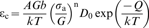
As an example, Type 316 austenitic stainless steel is widely used in nuclear power generation plant such as the UK Advanced Gas Cooled reactors (AGRs). A typical deformation mechanism map for the steady state creep response of this type of steel has been established by Frost and Ashby. 6 The deformation mechanism map was generated by fitting generic models to creep data. 6 Figure 1 shows the deformation mechanism map for this material with a typical grain size of 50 μm in the solution treated condition. Power law creep, dominated by dislocation movement, and diffusional creep are the two main high temperature deformation mechanisms (Fig. 1). The former dominates at a relatively high stress and the latter at a relatively low stress. Two widely accepted physically based models that describe diffusional creep deformation were proposed by Nabarro–Herring 9,10 and Coble. 11
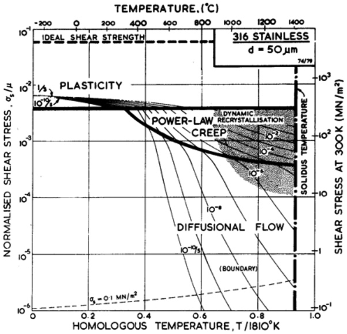
A deformation mechanism map for Type 316 austenitic stainless steel, with a typical grain size of 50 μm 6
Data to support the diffusional creep mechanism are limited, and most designs are assumed to fall within the regime where dislocation mechanisms dominate the material response. Many different forms of constitutive equations have been proposed to describe dislocation dominated creep deformation. 12–18 These include the power-law relationships employed by Frost and Ashby 6 and exponential and hyperbolic sine relationships. 17 However, to date no unified mechanistic models have been proposed and most of the equations simply provide a functional form of constitutive model that can be fitted to data. Thus the resulting models can be used to predict creep behaviour only within the bounds of test data. 19 There are at least two obvious drawbacks associated with the development of constitutive equations in this way: (i) the difficulty of transferring the model from one tested material to another and (ii) the limitation of predicting material behaviour beyond the test data range. This leads to the requirement of an expensive creep test programme to develop long-term creep lifetime predictions.
Because of the incomplete understanding of the dislocation creep deformation mechanisms, most mechanistic models can provide only a good prediction for nominally pure metals and simple solid solution alloys. 1,15,18,20 Nevertheless, there has been some success recently in the development of mechanistic models for the behaviour of nickel based superalloys. 21,22 Therefore, the development of physically based creep deformation models is required and remains a significant challenge, particularly if there is a wish to determine the creep behaviour of many engineering alloys for long durations.
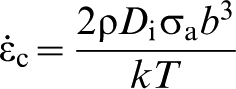
A useful method for describing the creep deformation of polycrystalline materials, i.e. creep deformation rate 
There has been a widespread acceptance of the idea that creep deformation is not driven by the applied stress but rather by an operative stress. Sometimes this operative stress is seen as the difference between the applied stress and the so-called ‘internal stress’, often considered to be representative of the material internal state. 29,30 Many different terms have been used to describe this internal stress concept, such as back stress, 29 friction stress, 31,32 threshold stress 33 and residual stress. 34 By incorporating a certain value of ‘internal stress’, attempts to reconcile differences between the theoretically derived creep stress exponents of the steady state creep rate and the experimental observations have been considered. 30 To validate the value of stress, which has been incorporated into a creep deformation model, many experimental techniques have been developed to measure the internal stress. 26,35–38 However, different measurement techniques seem to provide different magnitudes of the internal stress in the same material under very similar creep test conditions. For example, Blum and Finkel 38 creep tested an Al–11 wt.-%Zn alloy at 300°C for a range of applied stresses from 5·5 to 18·4 MPa. Both conventional and modified strain transient dip test techniques were used to measure the ‘internal stress’. Different magnitudes of internal stress were obtained depending on the technique adopted and the model employed to interpret the measured values. Therefore, data from measurements of internal stress do not necessarily permit a critical comparison with the theoretical derivations of the internal stress. Ambiguous definitions of internal stress and the inability to separate the internal stress from the internal resistance at different length-scales are two potential reasons leading to the contradictions.
In “Dislocation mechanisms in creep” section of this review, creep mechanisms associated with the dislocation structures in different classes of materials are briefly reviewed. In “Internal stress and internal resistance” section, the concepts of internal stress and internal resistance are established. The mechanistic creep deformation models incorporating internal stress and internal resistance terms are critically assessed in “Creep deformation models” section. In “Measurement of internal stress and internal resistance” section, the techniques available to measure both at different length-scales are critically assessed. Finally, concluding comments are given in “Concluding comments” section.
Dislocation mechanisms in creep
Introduction
When a polycrystalline material is subjected to applied stress at elevated temperatures, dislocation associated deformation requires the dislocations to overcome the intrinsic lattice resistance (Peierls force) and obstacles such as other dislocations, solute elements and second-phase particles/precipitates. 39 Thus, the magnitude of the resistance to dislocation motion is determined by the overall dislocation structure and density and the distribution and types of solute elements and particles/precipitates.
For a range of materials, including pure metals,
13,40,41
solid solution alloys
13,20,42–44
and engineering materials,
42,45,46
the most widely used form of the power-law creep equation is that originally proposed by Mukherjee et al.
47
and subsequently referred by several workers
13,48,49


Following Mukherjee et al.,
47
it is instructive to examine creep data in terms of a normalised steady state creep rate 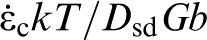
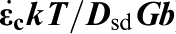
The diffusion coefficient compensated steady state creep rate (
Authors will now consider the contribution of different dislocation mechanisms to the creep deformation. These include the role of three-dimensional dislocation networks; heterogeneous dislocation cell/sub-grain structures; and the presence of solute elements and particles/precipitates. The authors examine these different mechanisms within the context of the power-law relationship of equation (1).
Three-dimensional dislocation network arrangement
Dislocations usually build up a randomly distributed three-dimensional dislocation network, with dislocations linked at nodes. 39 The detailed form of the dislocation network depends on both the internal and external factors. The most important internal factor is the stacking fault energy γ. 65,66 External factors include the stress and the temperature applied to a material. A low value of γ is associated with a random dislocation structure, which could be due to the difficulty for extended dislocations to cross-slip 65,67 or climb. 68 Such a dislocation arrangement is observed in austenitic stainless steels at relatively low temperatures 69 and α-brasses. 70
Several transmission electron microscopy (TEM) observations 71–73 have revealed that the three-dimensional network generated during creep consists of dislocation links connected at attractive and repulsive nodes. Figure 3 shows a TEM micrograph for a creep deformed 20%Cr–35%Ni stainless steel, where a dislocation node has just broken. Based on the observations of this type, Lagneborg 70 and McLean 32 have described a creep process in which creep strain occurs when a dislocation link breaks away from the network and glides on an active slip system, before eventually being arrested by other dislocations in the network. The distribution of link lengths in the dislocation network is determined by two processes: (i) hardening, arising from the increase in dislocation density as a result of the expansion of the released dislocation, and (ii) recovery, where longer links grow at the expense of smaller ones in a process akin to grain growth. It has been suggested by Suzuki and Imura 74 that smaller dislocation networks are unstable and grow rapidly by diffusion at high temperatures under the action of their line tension. Both Lagneborg 70 and McLean 32 argued that a dislocation link can break away from the network if it is longer than a critical value λth. Under steady state creep conditions there is a balance between the rates of hardening and recovery that continually supplies dislocations of the critical length required for permanent deformation to occur. Following a stress change, transient behaviour occurs as the dislocation structure evolves towards the steady state structure associated with the new stress level. The authors discuss this further in “Creep deformation models” and “Measurement of internal stress and internal resistance” sections.
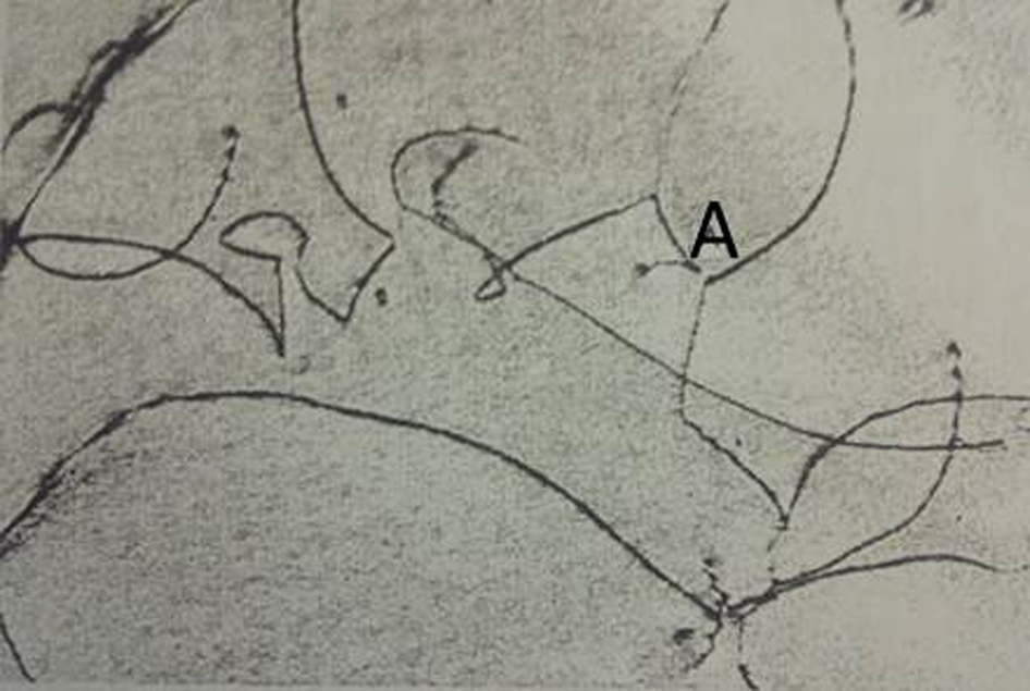
Dislocation structure during creep of a 20%Cr–35%Ni stainless steel, tested at 700°C and 343 MPa, showing the presence of dislocation node which has just broken at position A. Adapted from Refs. 1 and 70
Heterogeneous dislocation cell/sub-grain structure
For pure metals, such as Al 13 and other FCC metals, 40 BCC metals 40 and HCP metals, 41 a creep stress exponent of n close to 5 is often obtained. Creep data for pure Al with n = 4·6 are shown in Fig. 2a . It is well established that a stress exponent, n, close to 5 is typical of pure metals which develop dislocation sub-structures, i.e. a cell or sub-grain structure. 12 Sub-grain formation requires both dislocation cross-slip and climb to enable rapid rearrangement of dislocations. 65,67,75 A model which describes the creep response of the resulting dislocation sub-structure was developed by Blum and his co-workers 76–79 based on the earlier model of Mughrabi 37,80 for time-independent plastic deformation. In this model, each grain includes two distinct areas: the rectangular cells with thin walls containing dense arrays of dislocations and the cell interiors containing a low density of dislocations. The dislocations in the cell walls produce a large resistance to the motion of dislocations through the walls. 37,80 As a result, some dislocations in the cell interiors are held up at the interface between cell walls and cell interiors. At the cell interiors, the dislocations are arranged randomly as a three-dimensional network structure, which has been confirmed by TEM observations. 1,81,82 The authors consider this model further in “Creep deformation models” and “Measurement of internal stress and internal resistance” sections.
Solid solution
For solid solution alloys, Al–Mg, 13,20 Al–Zn 43 and Al–Cu 44 alloys are three typical examples where a creep stress exponent, n, close to three was obtained in the intermediate normalised stress region. Creep data of the Al–2·2 at.-% Mg and Al–3·3 at.-%Mg alloys are shown in Fig. 2a , where the creep mechanism is viscous glide of dislocations. 50 The intermediate normalised stress region for the Al–2·2 at.-%Mg is between σa/G = 3×10⁻⁴ and σa/G = 2×10⁻³, where the creep stress exponent n = 3·0 was obtained (Fig. 2a ). Both TEM and etch pit observations of creep deformed materials with n close to three have shown either a complete absence of the dislocation cell structure or a sluggish tendency to form a cell structure. 50,83 Dislocations interact in several possible ways with the solute elements, and as a result dislocation climb is impeded. 14,84 Cottrell and Jaswon 51 proposed that the drag process arises from the segregation of solute atmospheres to moving dislocations. The dislocation velocity ν is then limited by the rate of migration of the solute elements. Fisher 52 proposed that dislocation motion destroys the short range order in solid solution alloys and creates an interface. Suzuki 85 proposed a drag mechanism due to the segregation of solute elements to stacking faults. Furthermore, Mohamed 84 concluded that the Suzuki and the Fisher dislocation interactions with solute elements are necessary to predict the creep stress exponent of n = 3.
Creep data of Al–3·3 at.-%Mg (Fig. 2a ) show a deviation from n = 3·2 at σa/G>3×10−3. This indicates an increase in the value of n with the increasing applied stress. In fact, creep experiments on both Al–3·3 at.-%Mg and Al–5·6 at.-%Mg conducted by Yavari et al. 50,86 showed that the stress exponent n increased from 3 to 4·6 with the increase in the applied stress. When n was close to 3, there was essentially a random distribution of dislocations in the material, but a dislocation sub-structure formed when n was close to five. This indicates that rate controlling process changes to dislocation climb in the region where n = 5. It is generally agreed that this is because of the breakaway of dislocations from the solute atmospheres enabling them to glide much faster. The large difference in dislocation velocity between dislocations with and without the presence of the solute atmospheres was measured experimentally. 19 The gradual change from n close to 5 in pure metals to n close to 3 in solid solution alloys with increasing concentration of solid solution element (Fig. 2a ) has confirmed a physical relationship between the dislocation arrangement and the value of n. It is clear that dislocation climb and viscous glide represent two competing creep mechanisms in solid solution alloys, where the slower one becomes the rate controlling process.
Second-phase particles/precipitates
Dispersion strengthening is an efficient mechanism for improving the material strength at relatively low temperatures. 87 Orowan 88 was first to attribute this effect to the resistance of dislocations against bowing between impenetrable obstacles. The magnitude of the bowing stress is determined by the spacing between the obstacles. At elevated temperatures, it has been suggested that the stress required to move dislocations is only a fraction of the Orowan bowing stress. 29,89 This is because dislocation bowing between particles is an athermal process and depends little on temperature. 90 The experimentally observed critical stress to operate creep deformation in a Ni–20Cr–2ThO2 single crystal is below the measured Orowan bowing stress. 89
A kinked dislocation configuration, where the presence of local climb facilitates dislocation movement, was proposed by Lagneborg. 91 Reppich 92 suggested that the magnitude of the stress required for local dislocation climb over the particles is within 13–45% of the Orowan bowing stress. Dislocation climb models of this type implicitly assume that a dislocation is repelled by a particle. TEM observations of creep deformed oxide dispersion strengthened (ODS) alloys suggest that the detachment of dislocations from the departure side of particles is the rate controlling process, rather than local climb. 87,92–94 The calculation of the stress required for this process also gave a value smaller than that predicted by Orowan bowing.
Čadek et al. 95 analysed several sets of creep data obtained from aluminium alloy matrix composites reinforced by silicon carbide particulates, silicon carbide whiskers or alumina short fibres. High values of the creep stress exponent, n>5, were observed over a range of temperatures from 200 to 450°C. 95 In addition, a high value of creep stress exponent (n>5) was obtained by Lund and Nix 89 in creep tests on an ODS alloy Ni–20Cr–2ThO2. A schematic of the creep rate as a function of applied stress in dispersion strengthened and dispersion free materials has been produced by Arzt et al. 87 to illustrate three distinct creep regions with their characteristic creep stress exponents (Fig. 4). At high strain rates the material approximates the behaviour of the dispersion free materials, with n = 5 and self-diffusion activation energy. At intermediate strain rates, high values of stress exponent and apparent activation energy are often observed. At low strain rates, the stress dependence may decrease again to n = 5.
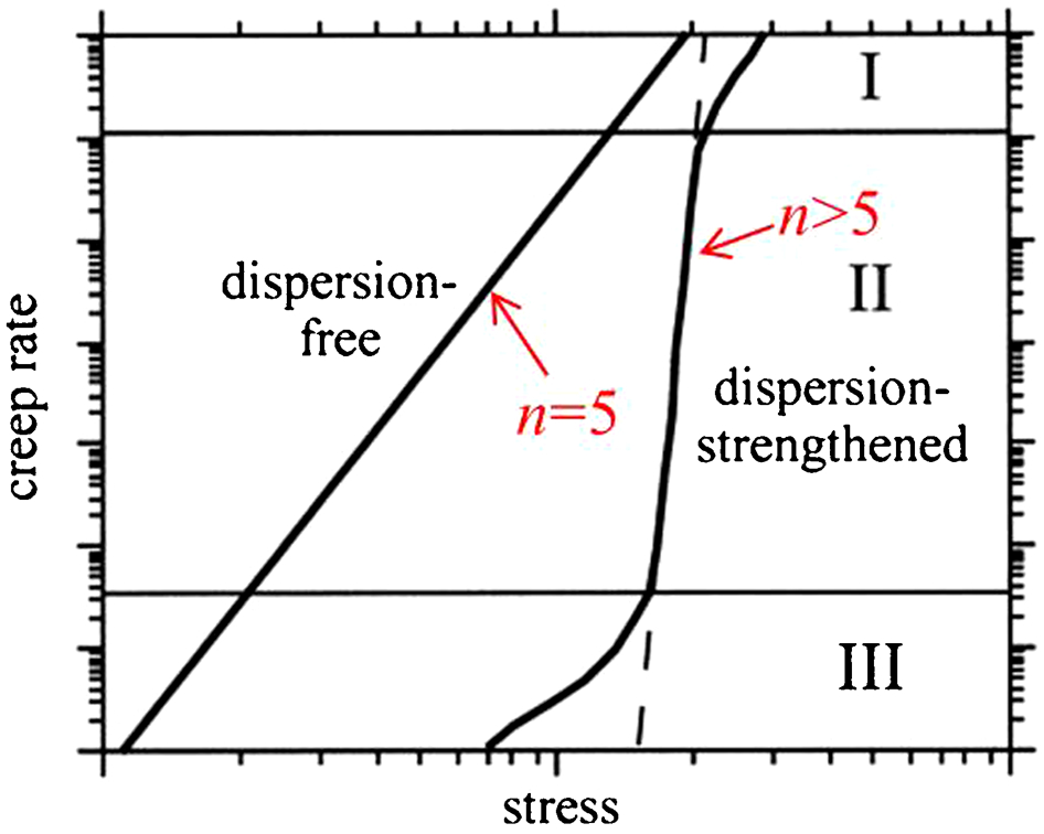
A schematic diagram of the creep rate as a function of stress in dispersion strengthened and dispersion free materials. Adapted from Ref. 87
The dislocation mechanisms responsible for the deformation of ferritic ODS alloys were studied using TEM, to examine the dislocation structure of creep deformed specimens up to a temperature of 1050°C. 96 At temperatures below 950°C, there was no evidence of sub-grain structure in the creep deformed ODS alloy. At relatively low temperatures from 650 to 750°C, dislocation motion was observed to be viscous glide controlled by solute drag. At an intermediate temperature range from 750 to 900°C, a thermally activated detachment of dislocations from oxide particles was judged to be the deformation mechanism. 96 A change in the mode of dislocation interactions with obstacles, i.e. the solute elements and the particles, was used to explain the change in the value of n observed in the different creep regimes (Fig. 4).
However, it has been demonstrated by Morris 69 that application of the same arguments regarding the dislocation interaction with M23C6 precipitates did not provide a completely satisfactory interpretation of the creep behaviour observed in Type 316H stainless steel. The presence of the M23C6 precipitates was a consequence of high temperature exposure of this material. Morris 69 claimed that the distribution of the precipitates defined the distribution of dislocation link length. When this link length was used for the calculation, a good prediction of the creep strain rate was obtained. 69
Creep of a complex engineering alloy
Having examined simple pure metals and their alloys as well as dispersion strengthened alloys, the authors now move to a complex engineering alloy, Type 316H stainless steel. The development of dislocation sub-structure in an austenitic stainless steel is shown in Fig. 5. The generation of a typical creep curve (Fig. 5a and b ) includes five steps: heating, loading, creep deformation, cooling and unloading. In laboratory creep tests, significant plastic deformation generally occurs on initial loading. During this loading step, the dislocation density increases dramatically 73 and the dislocations remain randomly distributed in a three-dimensional network (Fig. 5c ). This kind of three-dimensional dislocation network may be retained until the end of steady state creep (Fig. 5d ). However, if the temperature of a creep test is high enough, this dislocation structure can re-arrange gradually to form a cell structure (Fig. 5e ) or a sub-grain structure (Fig. 5f ). Both processes allow the material to minimise the overall energy by forming low energy boundaries. 25,39 The extent of this process depends on stress and temperature and it has been shown to vary grain-to-grain. 81,82 The grain-to-grain variation is because of the relative orientations of the slip systems to the loading direction, which determines the extent of the local plastic deformation and the evolution of the local dislocation density during deformation.
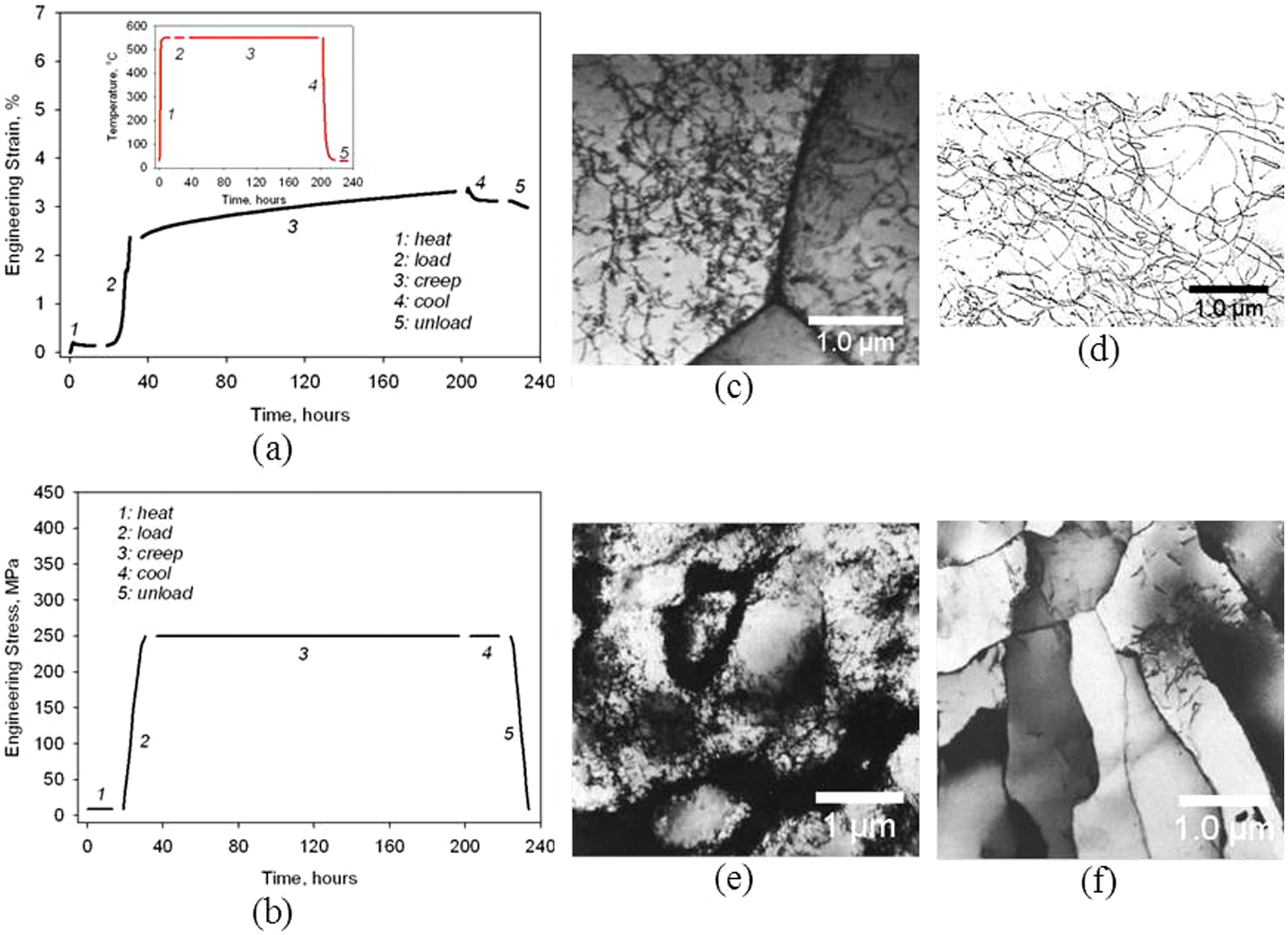
A typical creep test curve for austenitic stainless steel at 550°C and 250 MPa, together with the dislocation structures observed at different steps of high temperature tests: a and b five different steps of a creep test; c TEM micrograph 73 showing the dislocation structure produced during the loading step at high temperature (T = 400°C and ϵ = 2%); d TEM micrograph 1,70 showing a three-dimensional dislocation network in secondary steady state creep (T = 700°C and σ a = 107 MPa); e and f TEM micrographs 81 showing the dislocation cell structure (T = 700°C, σ a = 300 MPa, ϵ = 23%) and sub-grain structure (T = 750°C, σ a = 100 MPa) in secondary steady state creep
Creep data of Type 316H stainless steel obtained by Morris and Harries 45 showed various creep stress exponents, up to n = 22·3 for the test temperature of 525°C in Fig. 2b . The presence of a three-dimensional dislocation network was observed in the temperature range from 525 to 625°C. 45,69 Stress exponents from about n = 7 at low stresses to about n = 16 at high stresses, generated from several creep tests undertaken at 625°C, were also obtained by Morris. 69 The dislocation structure was characterised as a three-dimensional dislocation network for all tests. The high values of creep stress exponents (n>5) seem to indicate a change in the mechanism for dislocation creep deformation, since the theoretical predictions of the creep stress exponent based on the dislocation mechanisms are always less than five. 18,30,69,70 Creep data at temperatures from 625 to 900°C are shown in Fig. 2b . The creep stress exponent n decreases with the increasing temperatures as shown in Fig. 2b . At test temperatures of 750 and 900°C, values of creep stress exponent n = 5·8 and 5·5 are obtained. These values are consistent with the typical value of creep stress exponent in pure metals which develop sub-grain dislocation structures. When the creep tests were undertaken at a relatively high temperature of >625°C, 45,81,82,97 sub-grain dislocation structures were obtained for stainless steels.
Creep data of ex-service Type 316H stainless steel were collected by Chen 64 (500–600°C); a creep stress exponent of n = 6·4 was obtained, as shown in Fig. 2b . The dislocation structure in these specimens was likely to be dominated by the three-dimensional dislocation network, because of the relatively low test temperatures. 45,69 In fact, Bhargava et al. 98 observed that the presence of M23C6 precipitates in a Type 304 stainless steel inhibited the formation of sub-grain dislocation structures. A value of n = 5·6 is found based on the creep data of Fe–21Cr–37Ni stainless steel 30 (Fig. 2b ). Creep tests were undertaken within a temperature range from 600 to 750°C, where cell or sub-grain structures formed. 99 This value of n is similar to those derived from the creep data of ex-service Type 316H stainless steel (500–600°C) obtained by Chen 64 and the creep data of the same type of steel (>625°C) obtained by Morris and Harries 45 (Fig. 2b ). Thus it is likely that there is no difference in sub-grain structured and three-dimensional dislocation structured stainless steels in terms of their creep stress exponents. The authors explain this in “Origins of internal resistance” and “Model for a heterogeneous dislocation sub-structure” sections.
Summary
Different classes of polycrystalline materials have been considered in terms of the dislocation mechanisms operating during creep. In dislocation based creep deformation, dislocation glide and climb are two possible rate controlling mechanisms. Creep in pure metals reveals that the presence of a dislocation sub-structure normally gives a creep stress exponent of n = 5, whereas the presence of a three-dimensional dislocation network in solid solution alloys gives a creep stress exponent of n = 3. Dislocation climb is judged to be the rate controlling mechanism for the former and dislocation glide is the rate controlling mechanism for the latter. For the creep deformation behaviour of engineering alloys, such as Type 316H stainless steel and dispersion strengthened alloys, a higher value of n is often obtained for tests undertaken over a particular range of temperatures and stresses. Both dislocation cell structures and three-dimensional dislocation networks are possible in these creep tests. Dislocation interactions with other obstacles are the main reason for high values of creep stress exponent in dispersion strengthened alloys. At a certain range of temperatures, the activation energy for dislocation climb from obstacles becomes the rate controlling factor rather than the dislocation–dislocation interactions.
Internal stress and internal resistance
Concept
The term ‘internal stress’ has been used ambiguously in creep to describe the internal resistance of the material to creep deformation. 29 Here, the operative stress, defined as a difference between the applied stress and the ‘internal stress’, is the driving force for material deformation. Accordingly, the creep stress exponent describes the dependence of the creep strain rate on the operative stress. Different terms have been used in the literature, including threshold stress, 33 back stress, 29 internal stress, 26 friction stress 31,32 and residual stress. 34 These terms were introduced in the context of specific dislocation creep mechanisms.
The term threshold stress is often used to describe the dislocation based creep deformation of dispersion strengthened materials, where a certain value of threshold stress must be overcome in order for dislocations to bypass particles/precipitates. 29,90,100,101 Thus, the threshold stress is the lower limiting stress below which no measurable creep strain can be achieved. 102 It is envisaged that the mobile dislocations are arrested or slowed down at the particles/precipitates, by one of four possible mechanisms: 90 (a) particle shearing, (b) Orowan bowing, (c) global/local climb, and (d) drag of particles/precipitates. Both (a) and (b) are athermal processes. Global and/or local climb allows creep to occur at lower stresses than predicted by the athermal processes, because the activation energy for creep becomes lower for dislocation climb. 90,100 Particle drag requires diffusional rearrangement of the particles under the action of the forces exerted by the mobile dislocations. The diffusion coefficients for the particulate material are generally much smaller than those for the matrix and this process occurs only at large values of the homologous temperature. Therefore, particle drag is rarely observed under test conditions of practical importance. In general, the global and/or local climb of dislocations around particles is an important mechanism for particle strengthened materials. Hence, it is more appropriate to classify the threshold stress as an internal resistance term, reflecting the ease of the dislocation climb limited by the addition of the particles/precipitates.
The term back stress suggests the existence of an opposing stress to resist creep deformation when the material is subjected to an applied stress at high temperature. The occurrence of anelastic strain recovery (backflow) after removing part or all of the applied stresses from the creep deformed material has been judged to be an appropriate example for supporting the back stress concept. 103 The backflow is defined as the anelastic strain recovery, opposite to the straining direction at the maximum applied stress. It was claimed by Čadek 30 that the anelastic strain recovery in a material with a heterogeneous dislocation sub-structure could be attributed to two processes:
straightening of the bowed dislocation links under the applied stress and
reverse motion of dislocations in the cell interiors towards cell walls. The first process is associated with the disappearance of the equilibrium curvature of dislocation link under an applied stress. Thus this partly reflects the magnitude of the resistance that dislocations must overcome before moving.
The second process is associated with the localised internal stress field, such as that described by the heterogeneous dislocation sub-structure models developed by Dobeš and Blum
76
and Mughrabi
37,80
(Fig. 6). In this model, compatibility requires dislocations to flow within the cell interiors and through the cell walls. It is more difficult for the dislocations to break through the cell walls and thus a higher shear stress is generated in these regions than within the cell interiors. This is illustrated in Fig. 6 for both the stress at cell walls 


An illustration of the soft and hard regions of a dislocation sub-structure model with a representation of the local stress distribution across the cell where the cell wall has a finite width. Under an applied stress σ
a the cell wall has an internal stress


The term internal stress in the creep community is used to emphasise that the origin of this stress is from the material internal state. Internal stress and back stress are often used interchangeably by researchers;
30,38
both are widely used to describe the dislocation related material internal state. The difference between these two terms may occur when describing a stress state because of the presence of creep induced heterogeneous dislocation sub-structure. An internal forward stress 

The term friction stress was used by Wilshire and his co-workers 31,104,105 to rationalise large values of creep stress exponents. The friction stress appears to characterise the back stress associated with the heterogeneous dislocation cell structure developed during creep of polycrystalline Cu. 31 Thus, the friction stress takes the meaning of an internal stress term. However, Burt et al. 104 measured the friction stress for dislocation interaction with precipitates in a Nimonic alloy. Thus the measured friction stress takes the meaning of an internal resistance term. McLean 32 used the term friction stress to interpret the resistance to dislocation glide, which was controlled by the growth of the three-dimensional dislocation network. Therefore, it is unclear whether friction stress is a measure of internal stress or internal resistance. The existence of a period of zero creep after a sudden stress reduction during a creep test, which is the basis of the friction stress concept, has been questioned by Gibeling and Nix. 106
The term residual stress is used to describe those stresses that exist in the material in the absence of externally applied stresses. The classification of the residual stresses, i.e. Type I, Type II and Type III, is generally based on the length-scale over which they vary. 107,108 Type I (macro-) residual stress varies continuously over a length-scale, which is comparable to the macroscopic dimension of a component. Type II (meso-) residual stress self-equilibrates over the length-scale of grains. As a consequence, it is recognised that Type II residual stress is related to heterogeneity in polycrystalline materials at the grain and sub-grain length-scale. The grain-to-grain misfit stress is created by the orientation dependent elastic and plastic deformation within a polycrystalline material. 108–110 Rao et al. 34,111 attributed the presence of anelastic strain recovery in creep to Type II residual stress. Here, the residual stress clearly takes the meaning of an internal stress term. Type III (micro-) residual stress varies over a length-scale of dislocations. 107,108,112 This type of residual stress arises from the stress fields of dislocations and discrete dislocation/dislocation interactions. In terms of the individual dislocations, it proves more convenient in the current context to include the effect of the rapidly changing (both spatially and temporally) residual stress in the definition of internal resistance as discussed in “Origins of internal resistance” section.
After re-visiting different terms used for the so-called ‘internal stress’ in creep, it is clear that there is confusion about the meaning of the internal stress and internal resistance. There is a need to consider different terms in the context of the dislocation structure associated with creep deformation mechanisms, i.e. internal stress and internal resistance. In the following two sections, the authors will consider their origins and the characteristics of the length-scales for these two terms.
Origins of internal stress
The length-scale of internal stress is similar to the definition of Type II and Type III residual stress. 107,108 During deformation, different grain families deform to different levels, because of the elastic–plastic anisotropy of the grains. Both room temperature 109,113 and high temperature tensile tests 110 have shown the presence of internal elastic strains at a grain-to-grain length-scale following unloading. These strains are representative of the internal residual stress state. Using a self-consistent model, Clausen et al. 109 predicted the magnitude of Type II internal stress in different grain families.
As described before, the presence of the heterogeneous dislocation sub-structure, proposed initially by Mughrabi,
37,80
produces an inhomogeneous residual stress state, see 

In a stress free material, dislocation links are straight. They bow in response to the shear stress acting on the glide plane, with the radius of curvature R proportional to the magnitude of that stress acting on the dislocation τa (Fig. 7a ). Thus, measurements of the radius of curvature of bowed dislocations can be used to determine the Type III internal stress. The authors consider this further in “Measurement of internal stress and internal resistance” section.
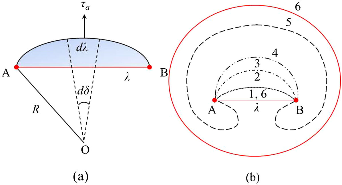
Schematic diagrams of a dislocation link under an applied stress: a curvature of a dislocation with a link length of λ, under a shear stress τ a; b development of a Frank–Read source from the initial step 1 to the final step 6
Origins of internal resistance
The internal resistance of a material depends on the dislocation density and arrangement as well as the distribution of solute elements and particles/precipitates when present. This provides barriers to both dislocation glide and climb. 1,96 The yield strength also depends on these features and can be used to provide a measure of the material internal resistance. This is consistent with the work undertaken in 2008 by Wilshire and Scharning, 3 where the yield strength of the material has been used to analyse creep deformation data.
Many mechanisms have been proposed to describe the change in internal resistance associated with dislocation creep processes.
32,70,81,114,115
These involve a range of processes which lead to changes in dislocation density and arrangement as well as variations in the mode of dislocation interaction with obstacles. In a material that forms a three-dimensional dislocation network, as illustrated in Fig. 3, the nodes at the end of a dislocation link must be broken to allow a dislocation to glide. Thus the interaction energy associated with the formation of a node is a measure of the internal resistance. Alternatively, the internal resistance can be viewed as the stress required to break a link from the dislocation network. For a regular repeating dislocation network, the critical resolved shear stress or the internal shear resistance of the network is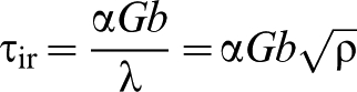
Lagneborg and Forsen
117
proposed that the internal resistance is determined by the longest dislocation link length λth that is immobile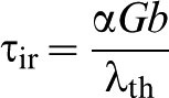
Thus, the applied stress has to be larger than this critical value to initiate permanent deformation. In this analysis, the dislocation structure is assumed to be the only source of the internal resistance. This is likely to be the case for pure metals. However, the presence of the other sources, such as the solute elements and second-phase particles/precipitates, may affect the overall material internal resistance. Accordingly, equation (3) needs to be modified
Although the curvature of a bowed dislocation is a measure of Type III internal stress, as described in “Origins of internal stress” section and Fig. 7a , the critical configuration is a measure of the maximum stress required before the dislocation becomes unstable, as shown schematically by step 4 in Fig. 7b . Thus the maximum curvature of the bowed dislocation is another manifestation of internal resistance. 39,118 Figure 7b shows a schematic diagram for the development of a Frank–Read source. 39 A new dislocation loop is generated after the dislocation becomes unstable, step 5 in Fig. 7b . However, it is clear that the experimentally observed dislocation structure with a bowed-out structure provides only a value of Type III internal stress which should be below the internal resistance. This is because the observed bowed-out dislocation structure is an equilibrium state rather than the stage that completes a new loop. After the development of the new loop, the dislocation link will be restored to its original length, step 6 in Fig. 7b .
For material, which forms a cell or sub-grain structure, the internal resistance to initiate permanent deformation could be attributed to the dislocation configuration within the cell walls, cell interiors or a combination of these two. Cell walls containing a high dislocation density might be treated as another obstacle to the dislocation movement and therefore another source of internal resistance. 37,80 Morris and Martin 58 claimed that the presence of a high value of internal stress is required in the sub-grain boundaries to ensure dislocation emission from the boundaries. This contributes to a permanent deformation.
Summary
It is now clear that the misfit strain creates internal stress, where a Type II internal stress varies over a length-scale comparable with the grain size and a sub-class of Type II internal stress reflects the difference of stress between the cell walls and cell interiors. They are revealed as genuine measures of internal stresses after the material is unloaded. In parallel, the density and structure of dislocations vary with creep deformation, leading to a change in the internal resistance of the material, as illustrated in Fig. 5c–f . In addition, the presence of other obstacles to dislocation motion may modify the internal resistance, as demonstrated by the creep response of dispersion strengthened alloys. Here, the authors emphasise the fundamental difference between these two terms: internal stress and internal resistance.
These two terms are readily understood by comparing the mechanical behaviour with respect to stress–strain diagrams for a bi-crystal. A schematic diagram is illustrated in Fig. 8, where no strain hardening is considered for simplicity, i.e. perfectly plastic strain and creep strain. Creep is a time-dependent plasticity and the authors describe the plastic strain and creep strain in a similar way in Fig. 8. The different stress–strain behaviours in grain A and grain B within the bi-crystal are shown in Fig. 8a
, while the externally applied stress–strain macroscopic behaviour of the bi-crystal is illustrated in Fig. 8b
. When the bi-crystal (Fig. 8c
) is loaded under an applied stress σa grain B yields first, followed by the yielding of grain A. The preferential yield of grain B leads to a change in the slope of the macroscopic stress–strain curve (Fig. 8b
). The slope determined from the line XY in Fig. 8b
is no longer a measure of the macroscopic elastic response of the bi-crystal because of the yield of grain B. Grain A still supports an increasing stress until it reaches yield (Fig. 8a
). The different yield points in each grain can be envisaged as a consequence of the different Schmid factors on the slip systems, as illustrated in Fig. 8c
. The indicated magnitudes of 


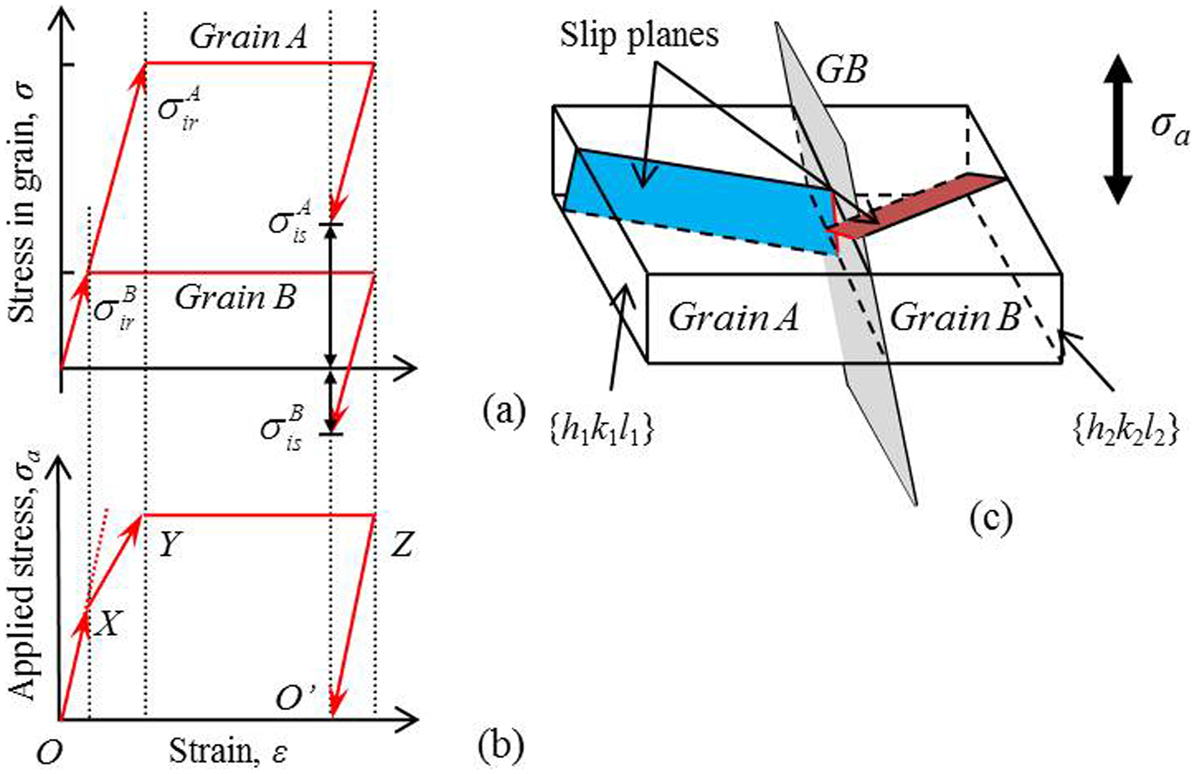
A simplified model illustrating the concept of internal stress and internal resistance in a bi-crystal, subject to an elastic, perfectly plastic and creep deformation, under applied stress σ a: a and b showing the stress–strain relationship in both individual grains and the whole bi-crystal; c showing the orientation of grain A and grain B, relative to the applied stress axis
If the bi-crystal given in Fig. 8 contains a pre-existing internal stress in the grains, determination of the internal resistance becomes difficult without prior knowledge of the internal stress in each grain of the bi-crystal. For example, the external stress was applied to this bi-crystal from point O′ in Fig. 8b
. As a consequence of the presence of a tensile internal stress in grain A and compressive internal stress in grain B after the first loading history, the applied stress required to create the preferential yield in the bi-crystal is then equal to the difference between the magnitude of 


Creep deformation models
Introduction
In “Dislocation mechanisms in creep” section the authors described the material response within the framework of a power-law constitutive model for the creep deformation rate (equation (1)). The authors now seek modifications to this relationship by taking into account the roles of internal stress and internal resistance as defined in “Internal stress and internal resistance” section. The authors start by examining in more detail the recovery creep model proposed by Lagneborg 70 associated with the development of dislocation networks within a material. The authors then evaluate models for particle (dispersion) and solute strengthened materials, which identify the roles of internal stress and internal resistance. Finally, the authors consider the individual role of cell walls and cell interiors in steady state creep and transient creep when either a part or all of the applied stress is removed using the composite model described by Blum and his co-workers. 76–79
Recovery creep model
Recovery creep models are based on the observation that materials harden with strain and soften with time.
1
The formulations of recovery creep models proposed by McLean
119
and Lagneborg
70
consider the dislocations to be arranged in a three-dimensional network. Based on detailed TEM examinations of dislocation link length distributions and the calculation of the fraction of mobile dislocations, Morris
69
provided a satisfactory interpretation of creep deformation in Type 316H stainless steel, tested at a temperature of 625°C and under stresses in the range from 200 to 395 MPa. The creep rate was described as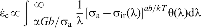
This equation was initially proposed by Lagneborg et al. 70,117 The value of ab/kT may be taken as approximately 4 and that of α close to 1. 69 σir(λ) is the internal resistance associated with dislocation link length and σa is the applied stress. The internal resistance σir(λ) is related to the length of a dislocation link through an equation of the form described in equation (2). θ(λ) is the number density of dislocation links with a characteristic length λ. The lower bound of the integration αGb/σa describes the separation of mobile and immobile dislocation links. The condition for a dislocation link to be mobile is λ>αGb/σir. It is only when the applied stress σa exceeds the internal resistance σir(λ) that a dislocation becomes mobile and contributes to strain accumulation. 117 Glide occurs when the nodes formed by dislocation links are broken.
The existence of an athermal component of the applied stress has been considered in Lagneborg's model.
70
When this athermal component originates entirely from the dislocation structure, the creep rate is then expressed by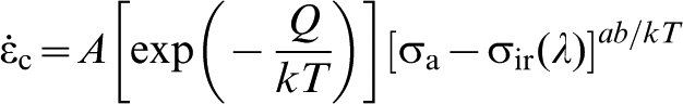
Creep model for particle strengthened material
Generally, the dependences of the steady state creep rate on applied stress and temperature for a material can be described by equation (1). The value of creep stress exponent n close to 5 or 3 has been observed experimentally, as illustrated in Fig. 2b
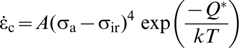
. However, a much higher stress exponent n has been obtained in particle strengthened materials within the intermediate levels of applied stresses, as shown in Fig. 4. This is accompanied with the presence of a high value of activation energy Q. Creep tests in a Nimonic alloy were undertaken by Williams and Wilshire.
120
Q = 460 kJ mol−1 and n = 8·3 have been obtained by them. The nickel self-diffusion activation energy was reported to be 280 kJ mol−6 and the activation energy for creep was much higher than this self-diffusion activation energy. Williams and Wilshire
120
proposed that the high values of Q and n could be accounted for in terms of the stress and temperature dependences of the internal resistance. The steady state creep rate 
Viscous glide model for solid solution material
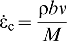
The creep rate because of dislocation glide has been described by Orowan
121
Model for a heterogeneous dislocation sub-structure
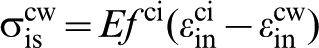
In “Heterogeneous dislocation cell/sub-grain structure” section, the effect of a heterogeneous dislocation sub-structure on creep deformation has been described, i.e. the rectangular cells with thin walls containing dense arrays of dislocations and the cell interiors containing a low density of dislocations. 37,80 Furthermore, the development of a sub-class of Type II internal stresses associated with this dislocation structure has been discussed in “Origins of internal stress” section, see Fig. 6. It is evident that both internal stress and internal resistance are associated with the heterogeneous dislocation sub-structure. The internal resistance associated with the dislocation density, dislocation link length as well as the distribution of solute elements and/or secondary-phase particles/precipitates when present have been discussed in “Origins of internal resistance” section. A composite model that accounts for the mechanical interaction between the cell walls and cell interiors has been developed by Blum and his co-workers. 76,78,79 In this model, it is assumed that the cell walls and cell interiors experience the same total strain (elastic plus inelastic). In their original model, they also consider the contribution to the total inelastic strain arising from migration of the cell walls. They acknowledge that this contribution is related to the deformation of the cell walls, but simply add it to the prediction of the composite model. The migration process results in a local incompatible strain and this should strictly be incorporated within the composite model rather than simply added as an additional term. In this section, the authors limit our discussion to the composite model, omitting any contribution from cell wall migration. The resulting description is consistent with the model described by Sedlacek and Blum. 77
The requirement of strain compatibility between the cell walls and cell interiors gives


Combining equations (10)–(12) gives the internal stresses in the cell interiors and cell walls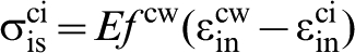
The important term in these equations is 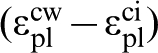
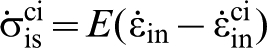
The inelastic strain rate and evolution of the internal stresses are obtained by differentiating equations (10)–(13) with respect to time

The inelastic strain rates in the cell walls and cell interiors can be expressed in terms of the local stresses using constitutive models such as those described in “Recovery creep model” section. The model is completed by providing an evolution law for the area fraction of cell walls f
cw.
76–79
In the steady state, 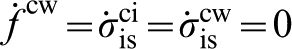
When part or all of the applied stress is removed from the specimen in a transient creep experiment, the internal resistance associated with the density and arrangement of dislocations in the cell walls decreases more rapidly than in the cell interiors as a consequence of recovery, because of the higher local dislocation density. It is instructive to argue that the relative change of the internal resistance to the internal stress in the cell walls determines the transient creep behaviour.
Measurement of internal stress and internal resistance
Introduction
Different types of internal stresses have been described in “Internal stress and internal resistance” section with respect to their characteristic length-scales over which they vary. For example, a Type II internal stress arises from the mismatch between a grain and its neighbours. Thus the magnitude of the internal stress is determined by the relative strength and orientation of its neighbours. Measurement techniques sample a variety of length-scales, thus they may record different stress values. Internal resistance originates from the dislocation arrangement and dislocation density as well as the interaction with obstacles. The magnitude of the internal resistance could be measured from a single dislocation, a group of dislocations or even an overall mechanical response of the material, i.e. yield strength.
This section describes techniques available to measure internal stress and internal resistance. These are summarised in Fig. 9, with their characteristic length-scales. These techniques can be classified as (i) dislocation; (ii) diffraction and (iii) mechanically based. Alternatively, the authors simply consider them in the layout of direct and indirect methods for evaluating both the internal stress and internal resistance. This is because the prime purpose is to use the measured values for the creep deformation models and improve the predictions of the models. Some of the techniques in Fig. 9 have been applied only at room temperature, but there is a potential to extend these techniques to studies addressing higher temperatures. For example, Chen et al. 123 have demonstrated that it is possible to measure by neutron diffraction the creep relaxation of Type I residual stresses in a weldment when subject to a stress relief heat treatment. In this case, measurements were made during the heating to 650°C, hold at temperatures, and the cooling cycle.
Schematic indicative of the internal stress/resistance measurement techniques covering a range of length-scales
In “Direct measurement of internal stress” section, the techniques classified as direct measurements of internal stress will be described, including radius of curvature of bowed dislocation (which is one type of dislocation geometry), convergent beam electron diffraction (CBED), electron backscattered diffraction (EBSD), synchrotron X-ray diffraction, and the conventional X-ray and neutron diffraction. The sampling volume of these techniques increases from the length-scale of dislocations to that of several grains (Fig. 9). In “Direct measurement of internal resistance” section, the techniques that provide a direct measure of internal resistance will be described, including dislocation link length (which is another type of dislocation geometry) and the Bauschinger and permanent softening effect test. The former measures a characteristic dislocation length-scale and the latter measures the overall behaviour of a bulk material (Fig. 9). In “Indirect measurement of internal stress and internal resistance” section, two indirect measurement techniques will be described: (i) analysis of peak asymmetry in X-ray diffraction and (ii) stress reduction type tests. The former provides a measure of internal stress and the latter provides some measure of internal resistance (Fig. 9). Indirect measurement techniques indicate that the interpretation of the measured result relies on specific dislocation based models. The authors cover both dislocation sub-structured materials and those exhibiting three-dimensional dislocation networks.
Direct measurement of internal stress
Radius of curvature of bowed dislocation
Morris and Martin
36,58
measured Type III internal stresses because of creep deformation in a Al–11 wt.-%Zn alloy. Specimens were creep deformed at different stresses (from 6 to 17 MPa) and temperatures (210 and 250°C). Dislocation sub-grain structures were observed in these creep deformed specimens.
36,58
The radius of curvature of bowed dislocations in both the sub-grain interiors and sub-grain boundaries was measured by TEM. A freezing technique was used in an attempt to retain the curved dislocations in their loaded state.
58
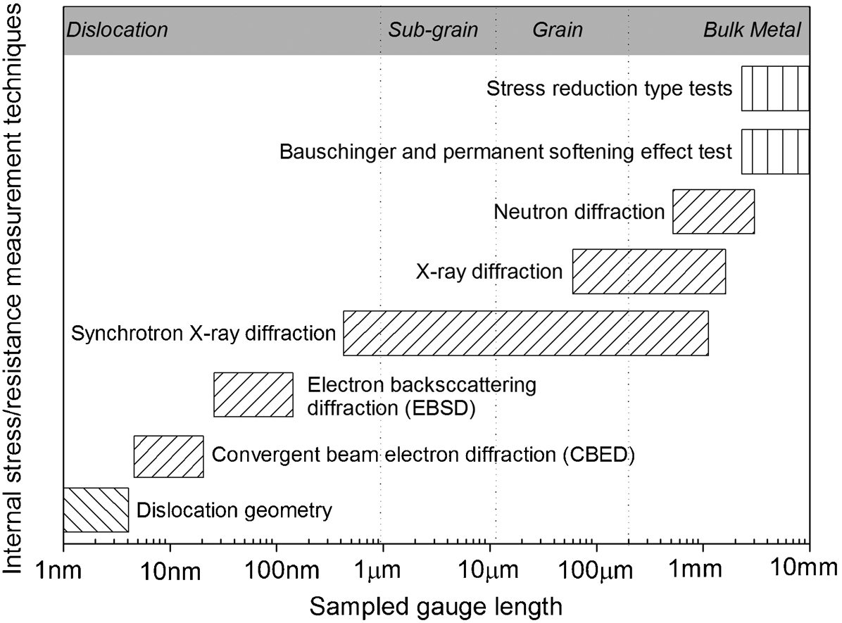
This was achieved by rapidly quenching specimens from the test temperature under the applied stress to room temperature. The dislocations remained bowed and from their radius of curvature R Morris and Martin
36,58
determined the effective shear stress (i.e. the local stress at loaded state) τe acting on the dislocation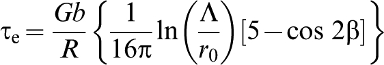
Using the approach adopted by Morris and Martin, 36,58 the internal shear stresses, τis = τe−τa, acting on dislocations were measured at both sub-grain boundaries and sub-grain interiors, for creep tested specimens (250°C and 8 MPa) interrupted at creep strains of 5, 7, 10 and 15%. 58 In this case, a steady state creep was achieved after 4% creep strain. Thus, these selected creep strain values are representative of steady state condition. The average sub-grain diameter was 30 μm. Several sub-grains were selected for analysis. 50-100 dislocations were measured for each sub-grain. The normalised values of internal shear stress with respect to the applied shear stress (τis/τa) are plotted against the distance from the sub-grain boundaries in Fig. 10. The applied shear stress in these creep specimens was 2·4 MPa (applied stress of 8 MPa times the Schmid factor of 0·3). Figure 10 shows that the calculated internal shear stress is about nine times of the applied stress for 7% creep strain, when the measurement was undertaken at sub-grain boundaries. This value increases to 16 times of the applied stress for a 10% creep strain and 25 times of the applied stress for 15% creep strain, as shown in Fig. 10. In addition, a much lower internal shear stress exists at the sub-grain interiors. These values are in contrast to results obtained after 5% creep strain, where the internal shear stress at sub-grain boundaries is similar to that at sub-grain interiors (Fig. 10). Thus, the high magnitude of Type III internal stress is associated with the dislocation sub-grain boundaries, which is consistent with the dislocation sub-structure model, as shown in Fig. 6.
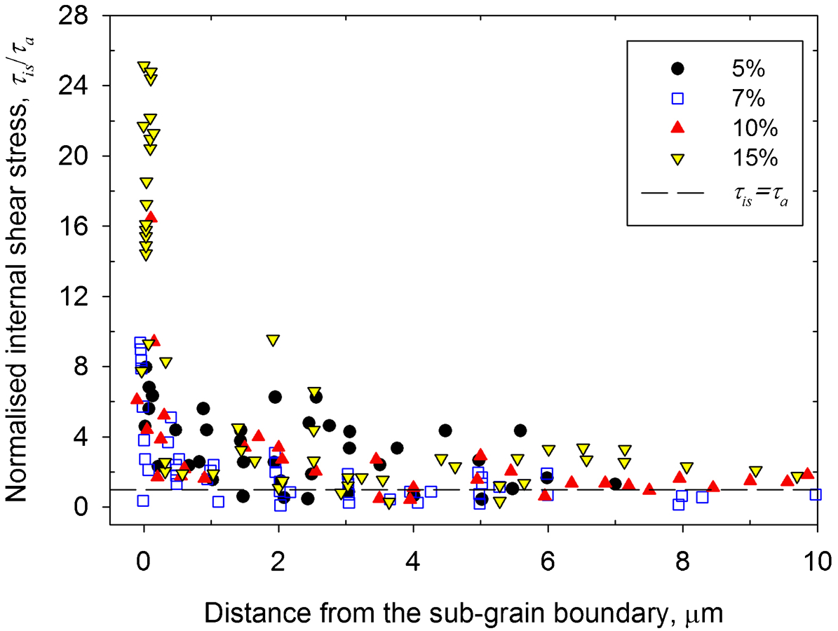
Distribution of the normalised internal shear stress (internal shear stress/applied shear stress) at sub-grain boundary and the change of its value with the distance from sub-grain boundary for different magnitudes of strains over the creep test (recalculated figure, adapted from Ref. 58)
Morris 69 also measured the radius of curvature of bowed dislocations in crept Type 316H stainless steel (tested at 625°C and 230 MPa). In this material, there were no cell/sub-grain dislocation structures observed using TEM. 69 For each specimen examined by Morris, 69 the internal stress acting on the dislocation was measured to be in the range of 0·25τa. The magnitude of Type III internal stress was estimated to be 58 MPa, one quarter of the externally applied tensile stress of 230 MPa. The absence of a sub-grain structure suggests that there is also a variation of the Type III internal stresses within material that contains a three-dimensional dislocation network.
Convergent beam electron diffraction
Convergent beam electron diffraction (CBED) applied to foil specimens for TEM studies provides a measure of localised lattice parameters with high accuracy and high spatial resolution using high order Laue zone (HOLZ) lines. 124 Lattice parameters are usually evaluated from the best match of the experimental pattern with computer-simulated patterns based on a kinematical approach. 125 The CBED experimental data are available to measure the internal stresses in room temperature cyclically deformed polycrystalline Cu, 126 creep deformed single crystal Al, 127 Cu 128 and polycrystalline Cu, 127 and severely room temperature deformed polycrystalline Al. 129 Most of these experiments were conducted to identify the changes in lattice parameters because of the presence of a dislocation sub-structure. 129
The CBED technique provides a measure of the stress field around a few dislocations and consequently these can be classed as Type III internal stress. The sampled gauge volume is determined by the incident electron probe size. Different probe diameters have been used previously, such as 5 nm by Maier et al. 126 and Straub et al., 130 20 nm by Alhajeri et al., 129 and 80 nm by Kassneret al.. 127,128 It has been shown that a group of dislocations may have a large value of internal stress when using a 5 nm diameter probe size, 126,130 but a corresponding larger group using an 80 nm diameter probe size may have a zero internal stress. 127,128 As a consequence, the variations in the measured results from zero to a significant value could be due to an inappropriate selection of electron probe size and reflect the fact that stresses vary rapidly in the vicinity of dislocations. Hence, the results can be sensitive to the characteristic length-scale over which measurements are made. The internal stress field associated with dislocations under an 80 nm length-scale could self-equilibrate, as claimed by Alhajeri et al. 129
The internal stress associated with dislocation cell structures, generated by room temperature cyclic deformation in polycrystalline Cu, was examined by Maier et al.
126
using an electron probe diameter of 5 nm. Measurements showed that dislocations at cell interiors had tensile internal stresses of ∼60 MPa when unloaded from the compressive part of the cycle. This magnitude of internal stress is equivalent to 40% of the saturation stress 
Straub et al. 130 studied Type III internal stresses induced by the presence of the dislocation cell/sub-grain structures in creep of polycrystalline Cu, using a 5 nm diameter electron probe. Compression creep tests at a constant normalised applied stress σa /G = 4·3×10−3 in a temperature range from 25 to 360°C were undertaken to generate the dislocation sub-structures. A tensile internal stress of 25 MPa in the sub-grain interiors was obtained for a crept specimen under compression (300°C and 162 MPa). But internal stress close to the sub-grain boundaries could not be measured because of the high dislocation density in that region. 130 Straub et al. 130 concluded that a tensile internal stress was present in the sub-grain interiors for the specimens crept under compression. The gradient of internal stress in the sub-grain interiors was observed to be relatively small. Close to the sub-grain boundaries, large stress gradients would be expected.
The above discussion illustrates the difficulty in measuring stresses at the length-scale of a few nanometres and in interpreting how these stresses are likely to influence the macroscopic creep response. Stresses at this length-scale vary rapidly and the result is very sensitive to the sampled volume. From a constitutive modelling perspective, the most important measures of Type III internal stresses are the volume averaged stresses in the cell walls and cell interiors within a given family of grains. At this length-scale, the cell structure associated internal stresses is judged to be a sub-class of Type II internal stress.
Electron backscattered diffraction
Electron backscattered diffraction (EBSD) offers a technique to measure both Type II and a subclass of Type II internal strains/stresses in a polycrystalline material, as indicated by the sampled gauge length of EBSD in Fig. 9. The grain orientation and sub-grain orientation can be also correlated with the measured strains/stresses. 131 Using this method, Type II internal stress in an austenitic stainless steel arising from room temperature plastic deformation (up to 10%) has been evaluated by Ojimaet al. 131 The measurements were performed before deformation (stress-free reference), during in situ loading and after unloading. The stress-free reference points were selected in each grain before deformation. By comparing the EBSD pattern in a stressed region with that of stress-free reference, the shifts of the zone axis in the EBSD-Kikuchi patterns, caused by the elastic strains and lattice rotations, were measured through cross-correlation based pattern shift analysis. 132 The detailed description of how the shifts were converted to strain and rotation tensors has been given by Ojima et al. 131
Figure 11a shows a typical stress–strain curve together with the EBSD measurement points at both unloaded and loaded states. In terms of the measurement during in situ loading, only four grains were selected, thus the conclusion based on this is judged to be not statistically convincing. In terms of the unloaded measurements, the specimen was loaded elastically to 239 and 284 MPa and then unloaded, as shown in Fig. 11a . Stress measurements, along the tensile direction, were undertaken in nine grains, where five grains had a <100> orientation and the other four had a <110> orientation. 131 In a FCC material, they are equivalent to measurements of {200} and {220} grain families. Many measurement points were selected in each grain. A percentage distribution of residual elastic strains at 0, 239 (unloaded state) and 284 MPa (unloaded state) were given in the original article by Ojima et al. 131 To show the values of internal stresses using the EBSD technique, the authors have selected the maximum values in the percentage distribution of residual elastic strains for each unloaded condition. The diffraction elastic constants (E 200 = 149·8 GPa and E 220 = 212·0 GPa), reported by Clausen et al., 109 have been used to convert the strain to stress, i.e. the internal stress. The derived internal stresses for the {200} and {220} grain families are shown in Fig. 11b . Grains 1–5 belong to the {200} grain family, where in general tensile internal stresses are present at the unloaded state. On the other hand, for the {220} grain family, including grains 6–9, both tensile and compressive internal stresses are present. The grain-to-grain variations can be explained in terms of Type II internal stresses. The magnitude of the stress on a grain is determined by the relative strengths and orientations of neighbouring grains. For a crystallographically texture-free material, the grains are orientated randomly and therefore each grain, which belongs to the same grain family, has different neighbouring grains. However, the measured values should be treated carefully, because their magnitudes are larger than expected, with the internal stresses ranging from −300 to 700 MPa, see Fig. 11b . It should be noted that local variations in chemical composition contribute to a change in the lattice parameter and therefore introduce a diffraction peak shift. In addition, the diffraction elastic constants for the specific grains in the material need to be established. Finally, the application of this technique at high temperature remains a challenge, because of the degradation of imaging quality when elevating the temperature for in situ testing.
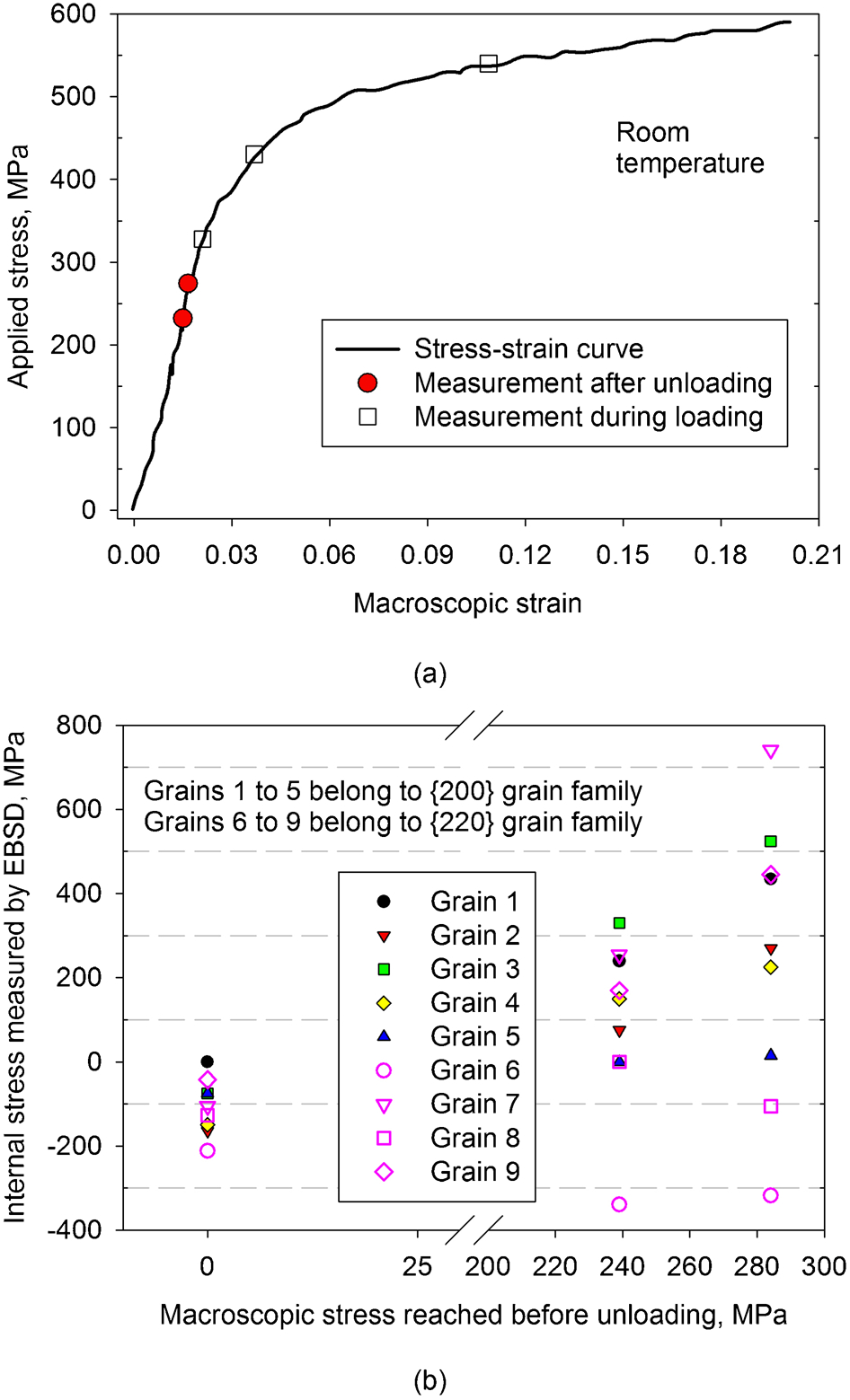
Internal stress derived from the EBSD measurements in room temperature tensile deformed austenitic stainless steel: a stress–strain curve and the measurement points, including both unloaded and loaded conditions (adapted from Ref. 131); b derived internal stresses for the {200} and {220} grain families
Synchrotron X-ray diffraction
The advanced photon source (APS) synchrotron provides an X-ray beam with a typical gauge length of 14 μm, which is smaller than the grain size of many metals and alloys. 133 Figure 12a shows schematically a typical set-up of the synchrotron X-ray diffraction in APS. A highly penetrating 52 keV high flux, narrow energy spread and divergence X-ray beam impinged on a test sample that is 300 μm thick and made from polycrystalline Cu with a grain size of 36 μm. The bulk polycrystalline specimen was subjected to a tensile stress at room temperature and the dynamic behaviour of individual, deeply embedded sub-grains was measured by Jakobsen et al. 133 Two detectors were used to obtain diffraction patterns on the grain length-scale (detector A) and sub-grain length-scale (detector B), respectively (Fig. 12a ). The latter corresponds to an angular resolution of ∼0·004° and is an order of magnitude better than that obtained by TEM. 133
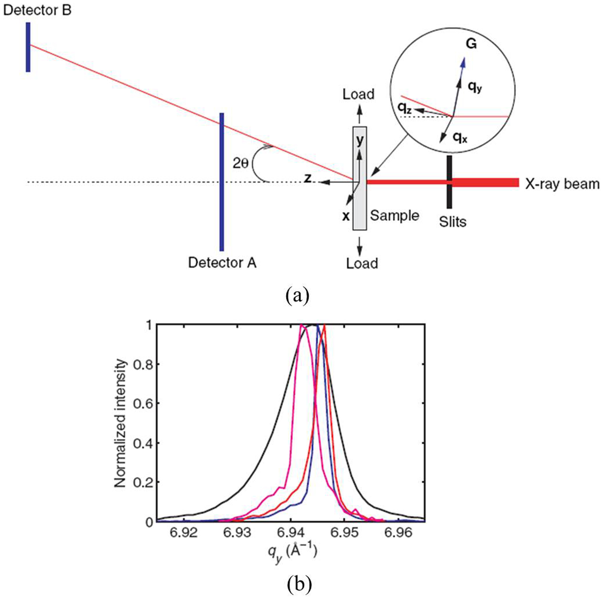
a schematic diagram of the experimental set-up. The real and reciprocal space coordinates (x, y and z) and (qx, qy and qz) are defined together with diffraction angle of 2θ. The direction qy (the radial direction) and (qx and qz) are parallel and perpendicular, respectively, to the ideal reciprocal lattice vector for the diffraction plane studied, represented by G. b The intensity distribution of some selected diffraction peaks appearing in the intensity map projected onto qy. The corresponding profile of the entire mapped intensity is indicated in black. Adapted from Ref. 133
Figure 12b
shows the intensity distribution parallel to the diffraction vector for selected peaks, which appeared in the intensity map projected onto the reciprocal space coordinate
A spatially resolved measurement of elastic strains within the cell interiors in a single crystal of Cu, deformed in tension and compression along the <001> axis has been undertaken using micro-beam diffraction, 0·5 μm diameter, scanning monochromatic differential-aperture X-ray microscopy (DAXM) at the APS. 134 The compression specimen was a 10 mm diameter and 20 mm long cylinder, and the tension specimen had a 5 mm square cross-section and was 10 mm long. These specimens were deformed at room temperature to a relatively large true stress of ∼200 MPa at a true strain of ∼30%. The DAXM specimens were then extracted from the centre of prior deformed specimens. Figure 13a and b shows the spatially integrated diffraction peak profiles (red curves) and the individual diffraction peak positions corresponding to each dislocation cell (vertical blue lines). The spatially integrated diffraction peak profiles exhibit an asymmetric shape with a skewed distribution at high diffraction angles for compression, red curves in Fig. 13a , and for tension skewed at low diffraction angles, red curves in Fig. 13b . In the compressive deformed specimen, all 12 peaks in Fig. 13a representing each individual cell interior are shifted to the left in Δq/q (q = 2π/d, d is the lattice spacing). A smaller q indicates a larger lattice spacing d. In the tensile deformed specimen, all nine peaks are shifted to the right, larger q but smaller d spacing (Fig. 13b ). This is consistent with the description given in the Mughrabi soft and hard region model. 37,135
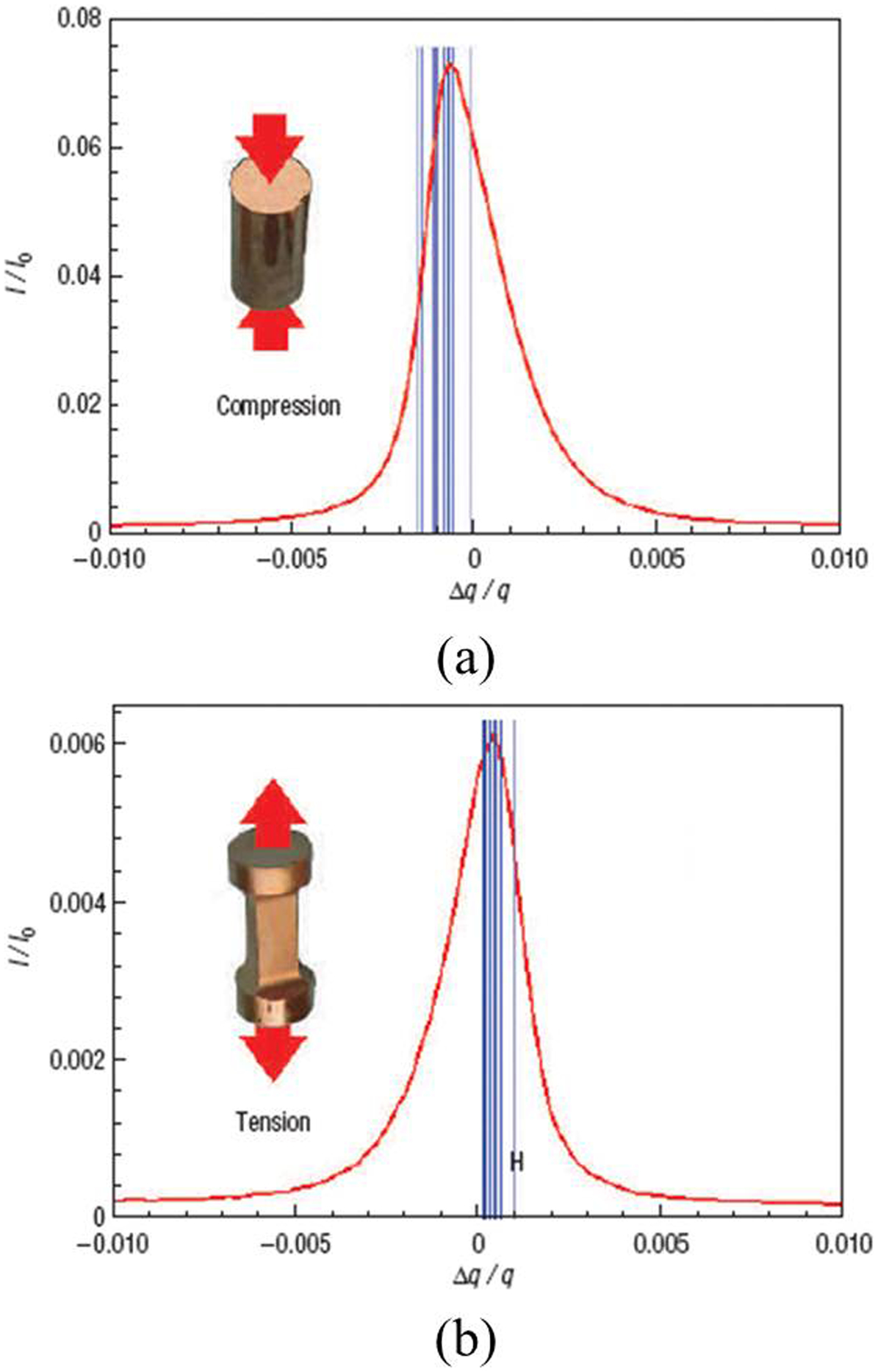
Comparison between the spatially integrated diffraction peak measured by conventional X-ray diffraction technique and spatially resolved measurements of peak position measured by scanning-monochromatic DAXM technique, for the deformed single crystal Cu: a compression specimen; b tension specimen. The red curves in both figures are spatially averaged axial {006} plane peak profiles obtained from conventional X-ray diffraction technique. The vertical blue lines show the corresponding diffraction peak centres from individual dislocation cell interiors, measured using scanning-monochromatic DAXM technique. Adapted from Ref. 134
The average elastic strains for the compression and tension specimens were measured by Levine et al. 134 to be 8·5×10−4 and 5·2×10−4, respectively, with a standard deviation of ∼1·0×10−4. Converting these measured axial elastic strains to stresses using a diffraction elastic constant for the {006} plane of E 006 = 66·6 GPa, 136 the magnitude of a sub-class of Type II internal stresses associated with the cell interiors is calculated to be 56·6 MPa in tension for the compressive deformed specimen and 34·6 MPa in compression for the tensile deformed specimen. Thus, the observed peak shifts, because of individual cell interiors (Fig. 13a and b ), provide a direct measure of a sub-class of Type II internal stress in the cell interiors. However, this observation is inconsistent with that reported by Jakobsen et al., 133 see Fig. 12b , where the diffraction peaks from each sub-grain interior could contain both tensile and compressive internal stresses.
Conventional X-ray and neutron diffraction
Historically, the presence of Type II internal stress in polycrystalline materials after being subjected to plastic deformation at room temperature was confirmed by using conventional X-ray diffraction. 137–140 This diffraction technique is inherently selective in terms of the grain orientations, thus it can be used to provide the stress state (Type II internal stress) from each grain family provided that Bragg's law is satisfied. 107 The main drawback of using conventional X-ray diffraction is that only the internal stress in the near surface material (<50 μm for Al) can be measured. 107 This problem has been solved by the development of the neutron diffraction technique, which offers a measure of the internal stress in the bulk material (200 mm for Al). These two techniques sample many grains in a material.
Neutron diffraction techniques have been used to measure Type II internal stresses in austenitic stainless steels subjected to creep deformation by Rao et al. 34,141 The development of internal stresses was obtained from a group of creep specimens, interrupted at different creep times for a fixed applied stress of 180 MPa and a temperature of 650°C. 34 Figure 14 shows the magnitude of Type II internal stresses in three grain families: {200}, {220} and {311}. Here the originally measured lattice strains have been converted into stresses using diffraction elastic constants for each crystallographic plane reported by Clausen et al. 109 Since the magnitudes of the transverse strains were not reported in their study, the Poisson contraction cannot be considered. Figure 14 shows that the strain incompatibility between grain families increases with test duration and thereby creep strain accumulated. The {200} grain family changes to a tensile stress and reaches around 100 MPa after 450 h at 650°C, whereas {220} becomes compressive, with a magnitude of about 20 MPa. In this case the internal stress is small in the {311} grain family after creep. The changes in the internal stresses for these three grain families are similar to those obtained from the room temperature and high temperature tensile tests. 109,142 This indicates that the magnitude of the strain incompatibility is determined by the strength of a grain relative to its neighbours, i.e. the generation of internal stress is likely a strain-dependent process rather than a time-dependent one.
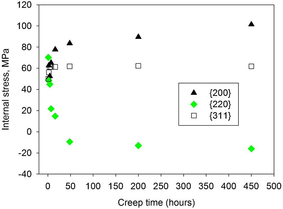
Derived Type II internal stress development in the interrupted creep samples measured using neutron diffraction by Rao et al. 34
Direct measurement of internal resistance
Dislocation link length
TEM examinations of prior crept 316H stainless steels were undertaken by Morris.
69
Thin foils were prepared from specimens crept to the steady state at 625°C and 250 MPa. The dislocation link length λ was determined using the following equation
Bauschinger and permanent softening effect test
Orowan 143 proposed a strain hardening theory, considering the presence of internal stress and gave a possible explanation to the stress–strain relationship on stress reversal, as schematically shown in Fig. 15. First, the material is plastically deformed along the OA curve in the forward direction. If the direction of the applied stress is reversed at some point after yielding, material is then deformed along the AB curve to C point. As shown in Fig. 15, part of the strain hardening developed by the forward straining is lost. This can be seen more clearly if the OAD curve was compared with the BC′ curve, which is the reverse straining curve of BC re-plotted. The transient softening of the material on stress reversal is called the Bauschinger effect, the horizontal hatched area in Fig. 15. This phenomenon is manifested by the early yield of the material if the direction of straining is reversed after the initial yield. 144 The vertical hatched area in Fig. 15 has been defined as permanent softening of the material, indicated by the stress σsn, which is equal to σf−σr at the same magnitude of absolute strain. Both σf and σr are measures of material internal resistance. Here, σf is the flow stress obtained if a monotonically increasing stress is applied to the material along the forward direction, OAD in Fig. 15. Thus, permanent softening can be measured at the same absolute strain and beyond the first few per cent of reversed deformation. Orowan 143 considered the magnitude of the permanent softening, σsn, to be a measure of internal stress, reflecting the difference between the internal resistance to the forward deformation (σf) and reverse deformation (σr).
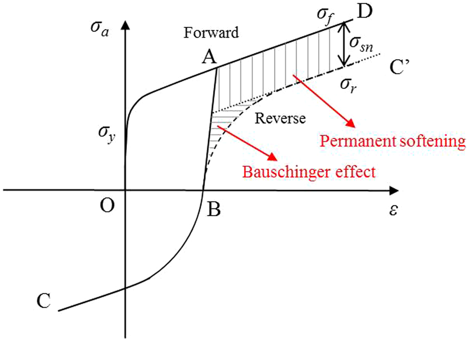
Schematic diagram showing the typical behaviour of a plastic deformed metal on stress reversal. Symbols σ y, σ f and σ r denote initial yield strength at forward straining, flow stress at forward straining and flow stress at reverse straining
Wilson 139 attempted to validate the permanent softening concept by measuring the internal stress. The approach was applied to several alloys with a cubic crystal structure. Several torsion specimens were prepared from a given material: each was pre-strained at room temperature to 9% and then subjected to one of a series of reverse strains in the range from 0 to 10%, 139 as illustrated schematically in Fig. 16a . The magnitude of permanent softening τsn was evaluated by the difference between the flow stress in the forward direction τf and the flow stress in the reversed direction τr. The specimen subject to a 9% forward strain and then 0% reverse strain, i.e. in the unloaded condition after forward straining, was used for the internal stress measurement by conventional X-ray diffraction (described in “Conventional X-ray and neutron diffraction” section). This approach offers information about Type II internal stress.
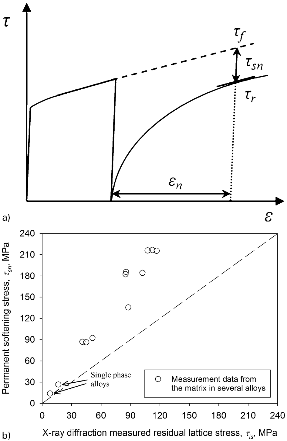
Relationship between the magnitude of permanent softening τ sn measured from the difference between τ f and τ r and the Type II internal stress measured by X-ray diffraction: a a schematic diagram showing the definition of τ f, τ r and τ sn in stress–strain curve together with the permanent softening strain ϵ n; b X-ray measurement data from Wilson's work 139
Figure 16b compares the permanent softening stress τsn with the X-ray diffraction measured Type II internal stress τis in several alloys considered by Wilson. 139 The selected alloys can be divided into two groups: (i) alloys that are mainly a single phase, as indicated by the arrows in Fig. 16b and (ii) dispersion hardened alloys. The magnitude of the measured internal stress in two alloys that are mainly a single phase is similar to the magnitude of the permanent softening stress, see the arrows in Fig. 16b . However, for the dispersion hardened alloys, the internal stress is only half the magnitude of the permanent softening stress (Fig. 16b ). It was concluded by Wilson 139 that the lower values of the measured internal stress τis were due to stress relaxation arising from both the unloading procedure and sample preparation. The latter was supposed to introduce a stress change in a ∼10 μm thick layer close to the free surface used for X-ray measurement. However, whether this large difference can be attributed solely to these two reasons is doubtful. X-ray diffraction provides a measure of Type II internal stress, whereas the value of permanent softening stress τsn is a measure of the difference between the forward and reverse internal resistances.
Indirect measurement of internal stress and internal resistance
Analysis of peak asymmetry in X-ray diffraction
Theoretical and experimental studies of the broadening of X-ray diffraction peaks in deformed crystals have been well developed. Peak broadening provides a measure of dislocation density which correlates well with TEM data. 35 Although this technique provides an indirect measurement of internal resistance, it has the advantage that it measures at the millimetre length-scale (Fig. 9). As described in equation (2), the internal resistance can be derived from the measured dislocation density. In addition, the presence of high dislocation density at cell walls or sub-grain boundaries can be inferred from a detailed peak profile analysis. 35,130 Profile analysis of broadened X-ray diffraction peaks in deformed crystals was based on the theory proposed by Wilkens, 145 where both the density and arrangement of the dislocations were considered.
Many X-ray diffraction studies have demonstrated that the diffracted peaks in the deformed crystals can be broadened and become increasingly asymmetric with increasing deformation.
35,130,135,146,147
All the X-ray diffraction measurements were undertaken at the unloaded state. For example, single crystal Cu deformed by wire drawing at room temperature to strains reaching 0·26 and 0·92, showed the presence of a dislocation cell structure.
146
Figure 17a
shows the typical X-ray peak profiles obtained from the {002} crystallographic plane for two deformation values ϵ = 0·26 and 0·92 together with the non-deformed state. The direction of the measured crystallographic plane was parallel to the applied stress. First, the full width at half maximum (FWHM) of the diffraction peak increases with the strain ϵ. The FWHM of the diffraction peak for ϵ = 0·26 is seven times and that for ϵ = 0·92 is nine times greater than the FWHM of the undeformed material (Fig. 17a
). Second, the peak profiles obtained from the deformed condition are increasingly asymmetric (Fig. 17a
). Assuming that the cell walls and cell interiors scatter X-rays incoherently, the asymmetric diffraction peak profile can be decomposed into two symmetric sub-peaks, as shown in Fig. 17b
. One peak represents the cell walls and the other represents the cell interiors. The separation of sub-peaks was interpreted using the model proposed by Mughrabi.
37
This has been described in “Model for a heterogeneous dislocation sub-structure” section. The integral intensities of each individual peak relative to the measured peak are proportional to the area fractions of the cell walls f cw and cell interiors f
ci respectively. The peak positions of the deconvoluted peaks (two symmetric sub-peaks) are shifted in opposite directions and this was expressed by the relative change in the lattice spacing Δd/d for the {hkl} crystallographic plane.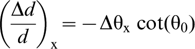
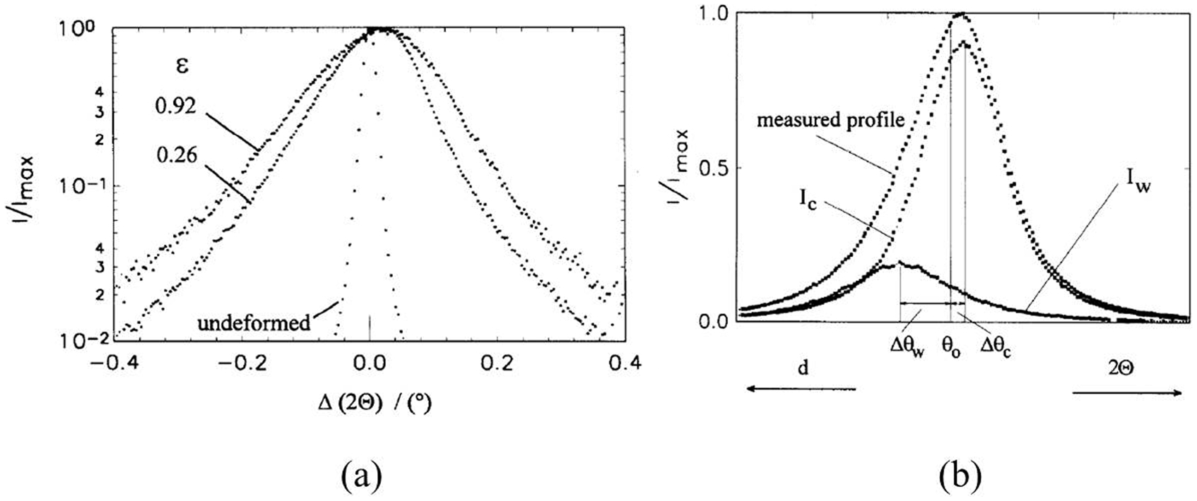
a Typical X-ray diffraction peak profiles of the {002} crystallographic plane of single crystal Cu, for the two deformation values ϵ = 0·26 and 0·92 together with the non-deformed state; b typical decomposition of an asymmetric diffraction peak into two symmetric sub-peaks. I w and I c represent the diffraction peaks from cell walls and cell interiors, respectively. Δθw and Δθc are the shifts of the sub-peaks relative to the centre of gravity of the measured peak profile. Adapted from Ref. 146
The internal stress associated with the dislocation sub-structures in a polycrystalline Cu was measured using the same method by Straub et al.
130
Compression creep tests were undertaken at different temperatures ranging from 25 to 360°C and under a constant normalised stress σa
/G = 4·3×10−3. Measurements showed that the increase in temperature had little effect on 

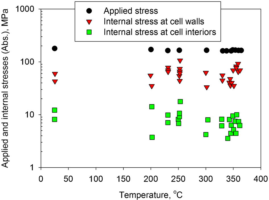
Internal stresses at cell walls (compressive stresses) and cell interiors (tensile stresses) measured by the analysis of asymmetric peak profile obtained from X-ray diffraction, together with the applied stresses (compressive stresses), was plotted as a function of the creep temperatures. Adapted from Ref. 130
Stress reduction type tests
A variety of stress reduction type techniques have been developed in an attempt to measure the so-called ‘internal stress’ in creep for different classes of materials, such as single crystal Al and Al–Mg alloys, 26,148 polycrystalline Al and Al–Mg alloys, 26,99 Al–Zn alloy, 38 Ni based alloy, 32 Fe–21Cr–32Ni 99 and Fe–21Cr–37Ni alloys, 30 Fe–3%Si alloy, 27 Type 304 austenitic stainless steel, 149 and Type 316H austenitic stainless steel. 114 These techniques include the incremental unloading technique, 148 constant structure stress reduction technique, 149 stress/strain transient dip test technique 26 and a modified transient dip test technique. 38 It has been claimed by different groups of researchers 26,30,32 that these techniques provide an average value of ‘internal stress’ over a significant number of grains in a bulk material, as indicated by the sampled gauge length in Fig. 9. However, these mechanical based techniques are now rarely used, because of the uncertainties in the measured values. 19,23,150
In general, stress reduction test techniques require that a certain proportion of the applied stress is removed during the creep test and the stress or strain transient is monitored instantaneously.
23,26,150
They are all based on an assumption that a constant dislocation structure is retained over the period of the rapid change in applied stress and the subsequent measurement. Thus, the measured values are a reflection of the microstructural condition at the moment before the stress reduction.
26
Another assumption is that the anelastic flow because of backward moving dislocations, driven by internal stress, exactly compensates for the continued forward moving dislocations, driven by the remnant applied stress. This leads to a zero net creep strain rate 
However, other investigators
30,32
have questioned whether the stress reduction measurements could be interpreted by a recovery creep model (see “Recovery creep model” section), where the duration of the time when 
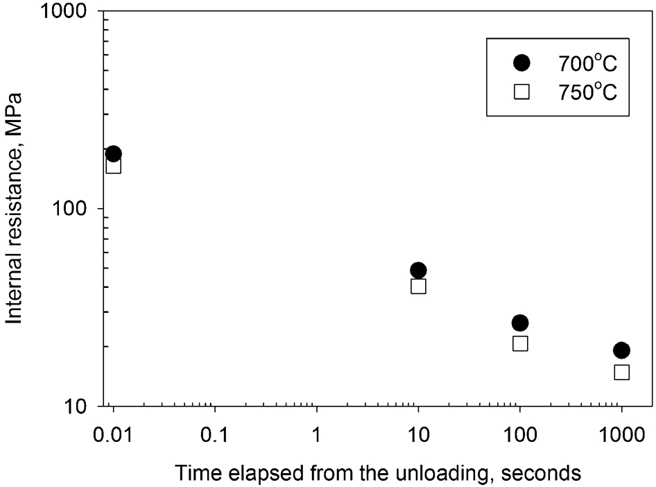
Internal resistance and its change with the elapsed time from the instant unloading, measured by a stress reduction type technique in the transient creep state of Type 316H austenitic stainless steel. Internal resistance data were collected from Ref. 30
The single stress relaxation test, shown in Fig. 20a , offers a very simple approach to measure the internal resistance. However, stress relaxation to a subjectively judged limit value takes considerable time, leading to errors arising from the creep recovery during the measurement, i.e. the constant structure assumption is no longer valid. 151 This single stress relaxation test was replaced by the incremental unloading technique, shown in Fig. 20b . In this case, the time required to reach the deformation limit, where no further stress relaxation occurs, is shortened by repeating the stress reduction in a series of unloading steps (Fig. 20b ). Early work by MacEwen et al. 148 attempted to use the incremental unloading technique to measure internal resistance. At various points in the tensile stress–strain curve, incremental unloading tests were undertaken on both single crystal Cu and single crystal Al–0·7%Mg alloy. 148 For single crystal Cu, a range of applied stresses from 1·2 to 22·9 MPa were studied. The measured values were 0·8 MPa for the former and 19·8 MPa for the latter. Thus, the ratio of the measured internal resistance to the applied stress was between 0·7 and 0·9. In terms of the single crystal Al–Mg alloy, the measured internal resistance was about 90% of the applied stress.
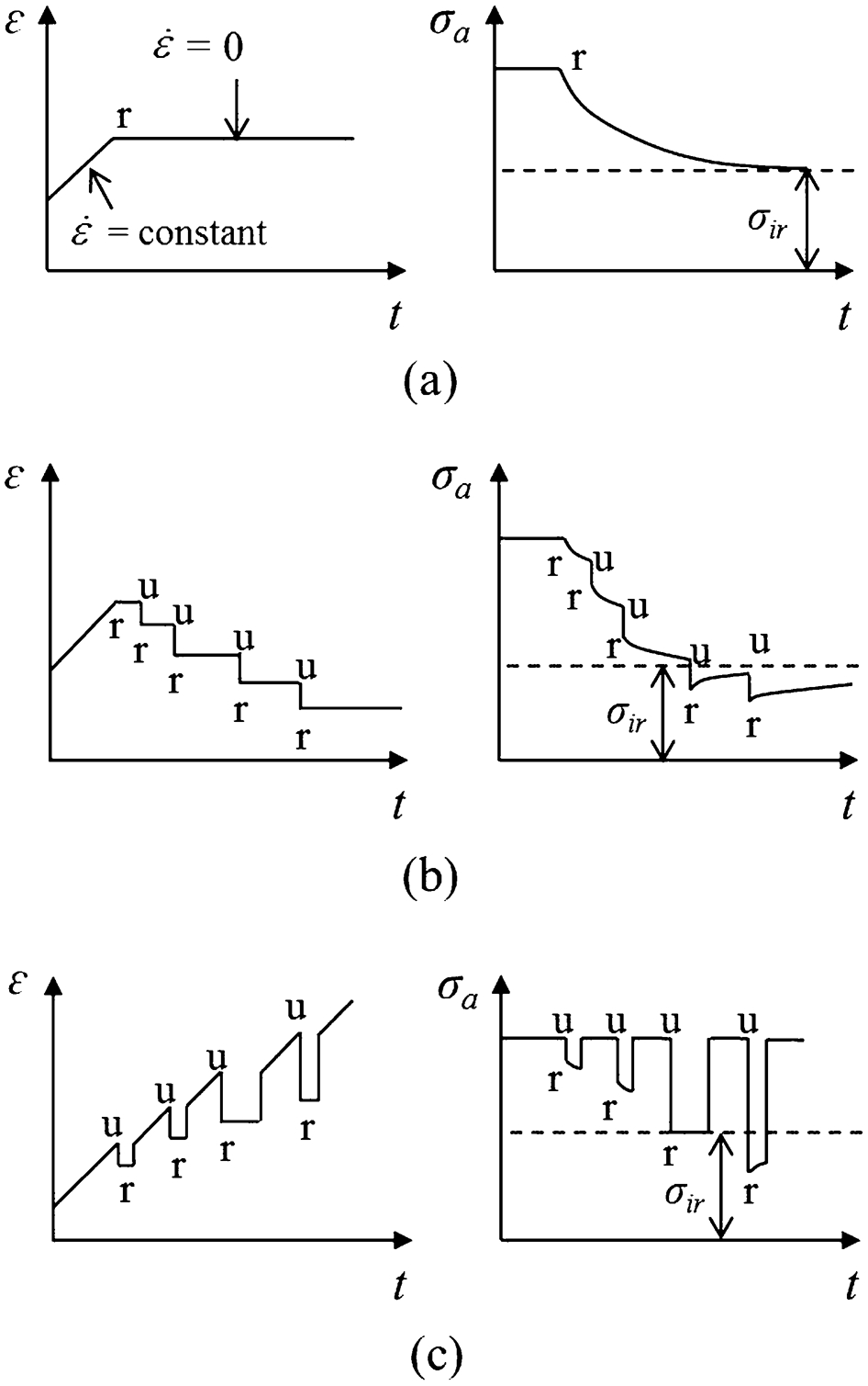
Schematic representation of the various methods for measuring the internal resistance σ ir by using stress reduction type techniques: a single stress relaxation, b incremental unloading and c stress transient dip test. Symbols r and u denote the moment for stress relaxation and unloading, respectively. Symbol t is time
Ahlquist and Nix 26 proposed a more widely accepted stress/strain transient dip test technique, which involves a series of unloading steps from an identical deformation state, see Fig. 20c for an illustration of the stress transient dip test. The stress or strain transient dip test technique measures either the stress change or the strain change after a reduction in applied stress. 26 The strain transient dip test technique was more often used to determine the internal resistance in creep deformed material, because this technique only required holding the stress constant. This can be easily achieved using conventional creep test machines. 152 Internal resistance measurements during steady state creep of Al and Al–Mg alloy were undertaken by Ahlquist and Nix. 26 Figure 21 shows the measurement results in polycrystalline Al, crept to steady state at 300 and 350°C under a range of applied stresses from 2·8 to 10·4 MPa. At a constant applied stress, the internal resistance decreases with an increase in temperature (Fig. 21). At constant temperature, the relative magnitude of internal resistance to applied stress decreases with an increase in applied stress, whereas the absolute internal resistance increases with applied stress. For the creep deformation at 300°C, internal resistances of 4·4 and 2·9 MPa were obtained for the applied stresses of 10·4 and 3·4 MPa, respectively.
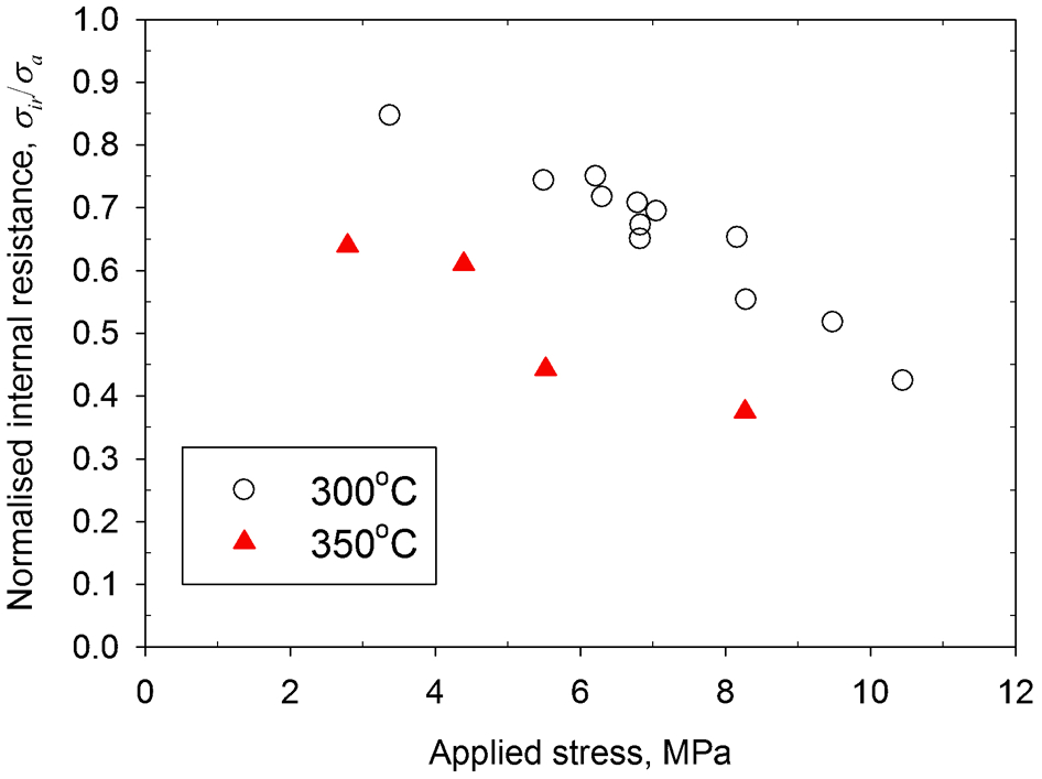
The ratio of the internal resistance to the applied stress in polycrystalline Al, measured by the strain transient dip test technique showing the temperature dependence and applied stress dependence of the internal resistance. Adapted from Ref. 26
Measurement of internal resistance during the primary creep stage was also attempted by Ahlquist and Nix. 26 However, this was unsuccessful because of the large errors in the measured internal resistance. This was attributed to the rapid change in dislocation structures during the primary creep stage, so that the constant structure assumption was no longer valid. 26 A key factor to judge whether the measured internal resistance reflects the internal state of a creep deformed material before the stress disturbance is based on how quickly the measurement can be completed. 23,150,153
In addition, Blum and Finkel
38
claimed that the determination of the deformation limit from the zero strain rate 

The measurement of internal resistance using a constant structure stress reduction technique was proposed by Cuddy 149 for specimens of Type 304 stainless steel subjected to different creep induced pre-strains, i.e. different internal states. Five specimens were creep strained to 15% at 247 MPa and 704°C, followed by reducing the applied stress to five different stress levels: 222, 200, 169, 147 and 124 MPa. The immediate creep strain rates after the stress reduction were measured for five separate tests and then plotted against the corresponding reduced stress levels. Absolute values of internal resistance were evaluated by two indirect methods.
In the first method, creep strain rate was described as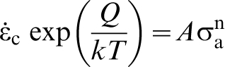
A and n values for the creep condition, strained to 15% at 247 MPa and 704°C, were obtained from equation (18). If more than one set of creep pre-strain conditions were considered, the values of A and n for each condition were plotted against the pre-strain stress σp. Five pre-strain conditions were created by Cuddy.
149
Extrapolating to σp = 0 gave the values of A and n for this condition σir = 0, i.e. σa = σop. σir is the internal resistance and σop is the operative stress. Thus the creep strain rate based on σop was described as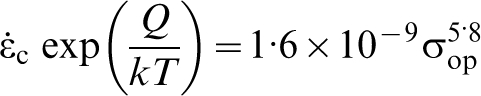
In this case, A = 1·6×10−9 and n = 5·8 were obtained by extrapolation as described above. Then for each creep pre-strain condition, the difference between the operative stress obtained by extrapolation and the applied stress at the same creep strain rate is a measure of the internal resistance σir.
In the second method proposed by Cuddy,
149
the value of applied stress σa required to maintain a given strain rate after creep pre-straining was plotted against the creep pre-strain stress σp. Extrapolating to σp = 0, where σir = 0 and σa = σop, gave a unique value of σop necessary to maintain each creep rate. Values of σir were then obtained from σir = σa−σop at constant creep strain rate 
The values of internal resistance obtained from these two methods were in good agreement and a relation between the internal resistance and the creep pre-strain stress was obtained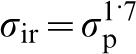
The ratio of the internal resistance to the applied stress σir/σa was in the range 0·10–0·25. The internal resistance measured by this constant structure stress reduction technique proposed by Cuddy 149 was much smaller than those measured using strain transient dip test technique, shown in Figs. 19 and 21.
Comparison of measurement techniques
In general, the internal stress and internal resistance measurement techniques have their characteristic length-scales, determined by the sampled gauge length relative to the controlling microstructural features, ranging from dislocation, sub-grain, grain to bulk material, as illustrated in Fig. 9. Typical results are summarised in Table 1 for internal stress and in Table 2 for internal resistance. The measured values relative to the initial applied stress are used in Tables 1 and 2. Thus, a positive sign for the relative value of the internal stress indicates that this stress has the same direction to the applied stress, and vice versa.
Summary of some typical measurement results for the internal stress using the techniques shown in Fig. 9
Summary of some typical measurement results for the internal resistance using the techniques shown in Fig. 9
RT: room temperature; HT, high temperature.
A specific sign is used for the ratio of the internal stress relative to the applied stress; a positive sign indicates that the internal stress has the same direction to the applied stress, and vice versa (RT: room temperature).
TEM measurement of the radius of curvature of bowed dislocations provides an evaluation of Type III internal stress associated with individual dislocation.
36,37,58
In the cell interiors that are composed of the three-dimensional dislocation networks, a value of internal stress 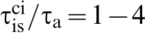
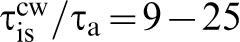
The high value of internal stress associated with a high dislocation density in the cell walls measured by TEM is inconsistent with the values derived from the analysis of peak asymmetry in X-ray diffraction. Analysis of peak asymmetry gave a value of 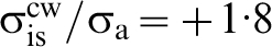
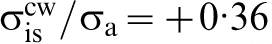
CBED can provide a measure of Type III internal stress when a few dislocations are present in the cell interiors, but cannot measure directly the internal stress at cell walls or sub-grain boundaries that contain a high density of dislocations.
126,130
A comparison between the results from the CBED technique and the analysis of peak asymmetry in X-ray diffraction shows a relatively good agreement, where the former gives a value of 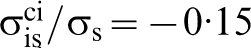
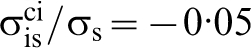
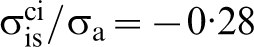
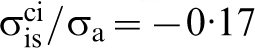
In terms of the internal resistance, two direct methods are available: (i) measurement of dislocation link length by TEM and (ii) measurement of material flow stress macroscopically in the Bauschinger and permanent softening effect test. The measurement of dislocation link length gave σir/σa = 0·5 (Table 2). This method has to assume that dislocation glide occurs by breaking the nodes formed by dislocation links. Measurement of material flow stress is feasible at room temperature. However, the possibility of using this technique at high temperature has not been considered.
After reviewing many techniques within the stress reduction type tests, it is clear that these indirect methods provide some measure of internal resistance when used in conjunction with a model. 26,30,38 These macroscopic measurements of internal resistance give a value averaged over the bulk material. After several years of modifications, the strain transient dip test technique could offer a reliable measure of the internal resistance in creep deformed material (σir/σa = 0·5–0·6 for Al–11 wt.-%Zn), 38 see Table 2. However, it is not possible to establish whether the change of dislocation arrangement representative of internal resistance, or the existence of a sub-class of Type II internal stress, leads to a zero creep strain rate after the applied stress was reduced to a critical value. This concern has also been put forward by Okazaki et al. 154 It would be instructive to undertake some stress reduction type tests combined with diffraction techniques, such as neutron diffraction and synchrotron X-ray diffraction to separate these two contributions. This combined approach would provide further insights into both the separate contributions and any potential correlation between them.
Direct observation of dislocation geometry created by the prior creep deformation using TEM can provide a measure of the internal resistance. Both Type III internal stress and internal resistance can be measured using TEM, see Tables 1 and 2. However, the main deficiencies of TEM are related to the thin foil specimens, 35 since the possibility of the loss and re-arrangement of dislocations during foil preparation and/or during observation is well-recognised. Two pinning dislocation techniques have been developed to retain the dislocation sub-structures in their loaded state for TEM examination. Pinning dislocations under load together with a quenching technique has been used by Morris and Martin. 58 Low temperature fast neutron irradiation has been used by Mughrabi 37 to pin dislocation sub-structures both after unloading and in the loaded state. Although success has been achieved using these two techniques, two fundamental limitations remain. First, TEM only images a small volume of material so that it becomes practically difficult to obtain a statistically representative measure of internal resistance. Second, the image overlap where high dislocation densities are present such as in cell walls or sub-grain boundaries makes the identification of individual dislocations difficult. 35
Concluding comments
This review has highlighted the importance of (i) separating internal stress and internal resistance in creep; (ii) establishing a link between these two terms and the dislocation creep mechanisms; and (iii) providing confidence in the measurement of these two terms by either direct or indirect techniques. The underlying need is for these two contributions to be incorporated into creep deformation models that improve the ability to predict overall creep life of components both at the stage of design and for the extension of the service life. A typical example of the latter is Type 316H austenitic stainless steel components used in AGR nuclear plant in the UK. To date several of these plants have operated for periods of more than 30 years. However, there is an expectation that it should be possible to extend the operating life by at least another 5–7 years. 155 To achieve this it is important to be able to predict the remanent life with high confidence. This requires that unnecessary conservatisms are removed which are included in the present assessment methodology. 156
From the above review, it is clear that both the internal stress and internal resistance are important when considering creep strain rate. There are several factors, which may lead to the changes in both the internal stress and internal resistance. For service components, this will be a combination of the initial microstructure of the material and the creep history over the service life. Type II internal stress has been shown to be a function of creep deformation time, i.e. creep strain (Fig. 14) where the relative strengths of grain families determine the magnitude of the internal stress. The increase in Type III internal stress arising from the creep deformation is shown to be a function of the creep strain (Fig. 10). The development of the dislocation sub-structure in creep deformed material, as described in Fig. 5, leads to the presence of high values of both a sub-class of Type II and Type III internal stresses. 150,157
Internal resistance originates mainly from three contributions: (i) dislocation to dislocation interaction, which is a function of both dislocation density and arrangement; (ii) dislocation interaction with solute elements; and (iii) dislocation interaction with second-phase particles/precipitates. This becomes an important issue for the Type 316H stainless steel components subjected to extended periods of high temperature service life. There will be progressive changes in the underlying microstructure of the material over the service life, such as the amount of second-phase precipitates with associated changes in the composition of the austenite matrix and changes in the density and arrangement of dislocations.
64,158,159
These changes arise from a complex interaction between the magnitude and state of the applied stress combined with thermal aging. Figure 22 shows a schematic diagram highlighting the influence of different sources of the internal resistance on the creep rate, where three contributions to internal resistance are considered. They are indicative of the contributions (i), (ii) and (iii) described above. For each creep deformation mechanism, there is an internal resistance represented by the critical stress required to effect deformation, see 


A schematic diagram showing the influence of different sourced internal resistance on the creep strain rate, where


Finally, the creep strain rate, 
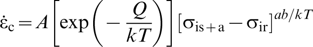
Footnotes
Acknowledgement
Authors are grateful for the financial support from EDF Energy. Bo Chen acknowledges with great gratitude the sustained support from his family members in China. Some of the ideas in this review were enlightened by the long-term research collaboration with Dr Shu Yan Zhang at ISIS, UK. Peter Flewitt acknowledges Wolfson College, Oxford University, for facilitating this collaboration. David Smith was additionally supported by the Royal Academy of Engineering and Rolls Royce plc.
The online version of this review was amended on 17 November 2014 to correct minor errors in the caption to Fig. 5. The source of part c is Ref. 73 and the correct source of parts e and f is Ref. 81.