
Abstract
Magnesium–lithium base alloy is one of the lightest metallic engineering materials with a density of 1·35–1·65 g cm−3, which is referred to as superlight materials. It has become an attractive material in the fields of aerospace, automobiles, portable electronics, etc. In this paper, the developing history and recent progress of superlight magnesium–lithium base alloys are reviewed. The progress on molten electrolysis preparation, processing technologies and surface processing technologies are introduced, and future research directions are suggested based on the current research progress.
Introduction
Magnesium–lithium alloys are attracting more and more interest for both scientific research and industrial applications because of their inviting properties, such as super lightweight, relatively high specific strength and stiffness, and good formability. Magnesium–lithium alloys can reduce the density down to 1·35–1·65 g cm−3 because of the addition of the lightest metal, lithium (Li), which is only nearly half of the density of aluminium-based alloys. Alloying magnesium with lithium can also change the crystal structure of magnesium. Solid solution of magnesium alloys with low lithium contents retains the hexagonal structure (the so-called α phase) and shows a moderate strength and a low formability because of the basal slip domination. The ductility is much improved with larger additions of lithium, which bring about the formation of the body-centred cubic phase (the β phase) but the strength is then notably lowered. With a suitable lithium content, a two-phase structure (α+β) can be obtained, leading to an interesting compromise since it combines the moderate strength of the α phase with the excellent ductility of the β phase. The Mg–Li base alloys can also be strengthened by introducing strengthening agents, such as rare earth elements and/or other alloying elements.
Even though the Mg–Li base alloys possess these advantages over other alloy systems, there still exist some drawbacks limiting their wide applications. The main drawbacks can be summarised into three aspects. First, both Mg and Li are highly active elements. Specifically, involving Li in the Mg–Li base alloys brings significant difficulties for the preparation and processing of Mg–Li alloys as a result of Li oxidation even at room temperature. Second, the low corrosion resistance is the main concern of the Mg and Mg–Li base alloys for industrial application. The third one is the relatively low strength of Mg–Li base alloys. To deal with these drawbacks of the Mg–Li base alloys, a wide variety of approaches have been proposed recently. For instance, molten salt electrolysing methods have been proposed to prepare for the Mg–Li base alloys. If Mg–Li base alloys are directly prepared by molten salt electrolysis, it is not necessary to strictly control the purity of raw materials since some so-called impurity elements can be alloying elements to enhance mechanical properties for Mg–Li based alloys. Another important advantage concerning molten salt electrolysis is that the effect of alloying during electrolysis makes the electrolytic temperature sharply decreased, and the current efficiency remarkably improved in comparison with electrolytic preparation of single metal. Therefore, molten salt electrolysing method is an important supplemental method to traditional melting and casting methods. Extensive efforts have also been made to enhance the mechanical properties of Mg–Li base alloys. On the other hand, for the application of Mg–Li base alloys in different fields, a significant amount of surface technologies have also been developed to protect the Mg–Li base alloys, such as electroless plating, conversion coatings, anodising, and micro-arc oxidation (MAO). With the demand of conductivity, the metallic coating for Mg–Li base alloys is attracting more and more attention.
Mg–Li base alloys have intrigued a number of research groups working on alloy research and developments as a result of their inviting properties and promising applications. This paper cannot include all the research aspects of Mg–Li base alloys. The emphasis will be placed only on the processing and mechanical properties, the molten salt electrolysing preparation method, and surface technology applied to the Mg–Li protection following a brief introduction of Mg–Li development history.
Processing of Mg–Li alloys
Casting technology
The commonly used casting method for Mg–Li alloys is gravity casting. If the casting process is conducted in air, the melt should be covered with protective flux (LiCl∶LiF = 3∶1). The height/diameter ratio of the mould should also be as high as possible. When the casting is carried out in argon atmosphere, the melting and casting are often conducted in a sealed chamber, which is evacuated first and then filled with argon gas. Besides the gravity casting method, pressure die casting, rapid solidification and semi-solid forming are also used to prepare Mg–Li base alloys. The advantages of the three casting technologies are listed in Table 1.
Advantages of the three casting technologies of pressure die casting, rapid solidification and semi-solid forming
Pressure die casting
In pressure die casting, as the melt temperature of Mg–Li base alloys is usually about 600–700°C, the cold chamber die casting method is always used. In this process, the pressure is an important parameter. Regener et al. 1 investigated the effects of two levels of pressure (I and II were used to identify the pressure values, whereby II is larger than I) on the microstructure and mechanical properties of Mg–10·7Li–0·6Al. The higher pressure results in the finer microstructure of the alloy (Fig. 1). The strength and elongation of the alloy are also increased by an increase of pressure (as shown in Table 2).
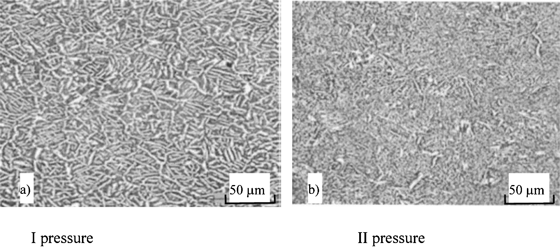
Effect of pressure on the microstructure of pressure die cast Mg–10·7Li–0·6Al
Mechanical properties of pressure die cast Mg–10·7Li–0·6Al under different pressure
Semi-solid forming
There are several methods for semi-solid forming, such as mechanical stirring, electromagnetic stirring, and strain induced melt activation (SIMA). Among these methods, SIMA is the most commonly used in the preparation of magnesium alloys. In the SIMA process, the strain and temperature are the two main parameters affecting the microstructure and properties of alloys. Figures 2 and 3 show the effects of the strain and temperature on the microstructure of Mg–Li–Al–Ca alloys. 2 A proper temperature produces a fine microstructure; too high or too low temperature makes the microstructure coarser. Higher strain results in finer microstructure. Through semi-solid forming, the strength of Mg–Li–Al alloys can be improved. Figure 4 shows the comparison in strength of the alloys fabricated by traditional casting and semi-solid forming. It is obvious that the strengths of the semi-solid formed Mg–Li–Al alloys are higher than those of as-cast alloys.
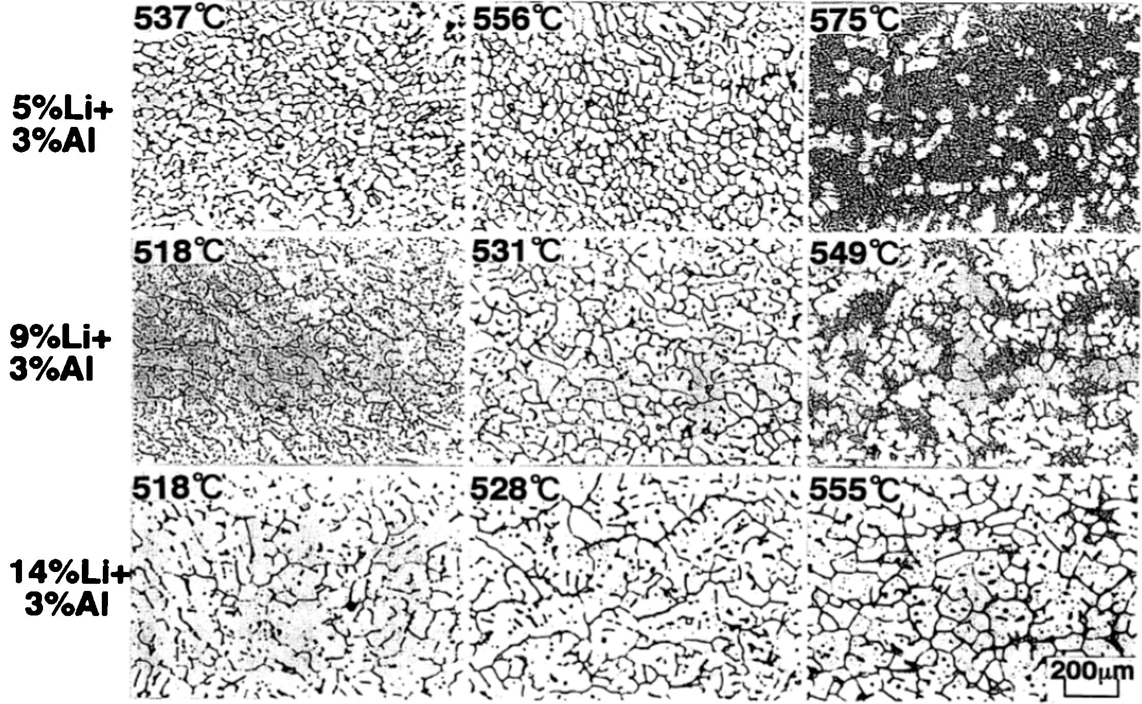
Microstructural changes of 15% strain-introduced Mg–Li–Al–2%Ca alloys under different semi-solid forming temperature

Microstructural changes of a Mg–9Li–3Al–2Ca and b Mg–14Li–3Al–2Ca alloys introduced various amount of strain. Specimens were heated at semi-solid temperatures of a 547°C and b 549°C
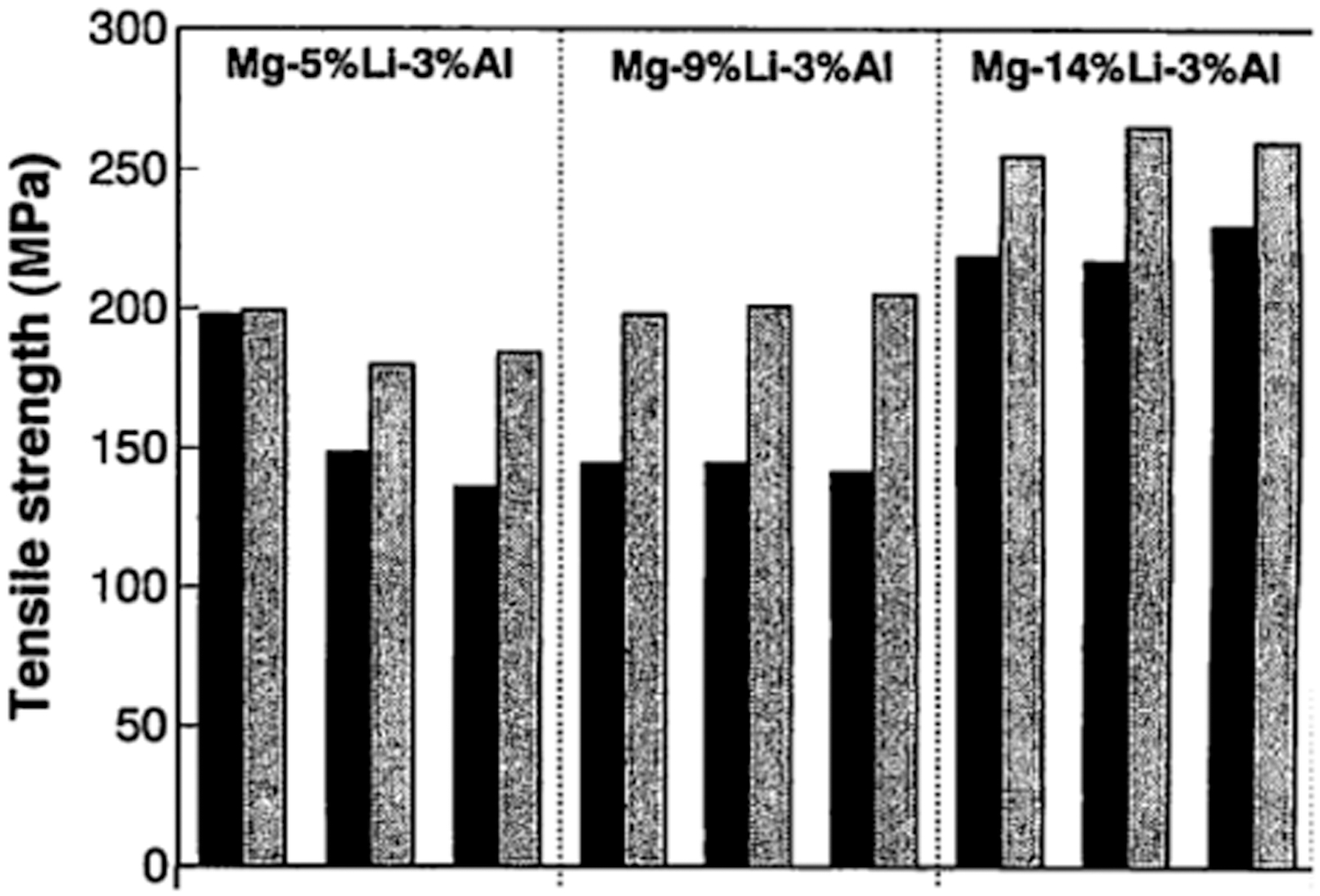
Strength of as-cast and semi-solid press-formed Mg–Li–Al alloys
Rapid solidification
In the preparation of Mg–Li base alloys, rapid solidification technologies include: twin roller quenching, melt spinning and spray casting.
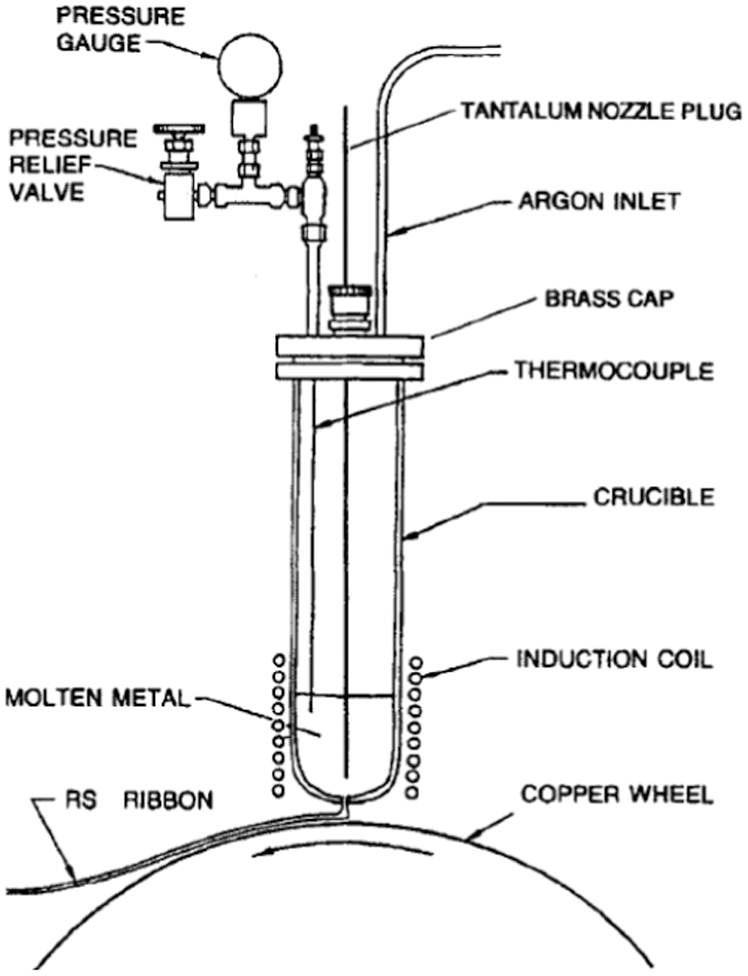
Figure 5 is the schematic of the twin roller quenching method. In this process, the charge is melted in a tubular crucible. Then, the melt is shrouded by argon gas and expelled from the crucible. The melt coming from the tubular crucible is rolled and quenched by two rotating copper rollers. In this way, ribbon alloys are obtained. Meschter and O’Neal studied the microstructures of the alloys of Mg–9Li, Mg–9Li–1Si and Mg–9Li–1Ce prepared with the twin roller quenching process and the conventional process. Results showed that the twin roller quenching produces microstructural refinement by a factor of 10–30 as compared to conventional processing. 3
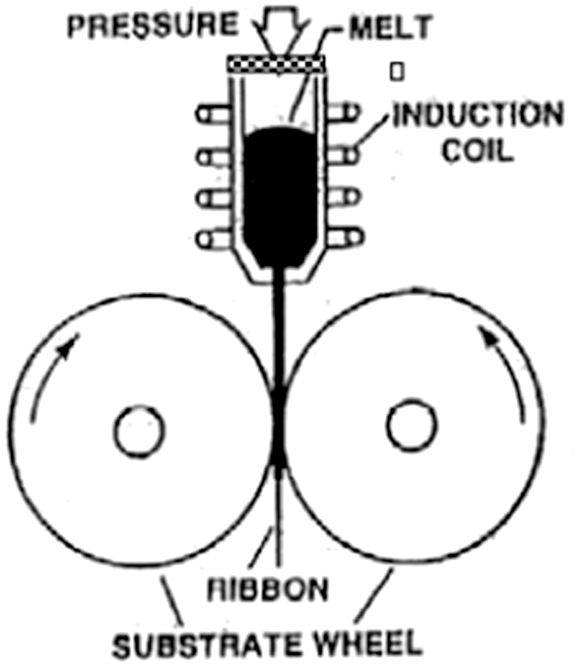
Schematic drawing of twin roller quenching process
Figure 6 is the melt-spinning apparatus. In this process, the melt was also shrouded by argon gas and expelled from the tubular crucible. The melt coming from the tubular crucible was quenched by a high speed copper wheel and a solidified ribbon sample was obtained. Matsuda et al. 4 used this process to prepare Mg–13Li–4Si–1Ag specimens with a thickness of 50–100 μm. The specimens possessed homogeneous composition, a fine and uniform distribution of the intermetallic phase (Mg2Si, 2–3 nm), and a highly fine-grained matrix.
Melt-spinning apparatus
During the spray casting process, melt is sprayed in a nozzle by an atomiser and consolidated on a substrate disc (Fig. 7). Figure 8 (Ref. 5) shows the comparison of the microstructures of Mg–Li alloy under two casting conditions (chilled casting and spray casting). The precipitated phase in the alloy is needle shape in the chilled casting specimen, while in the spray casting specimen, the precipitated phase is particle shape and distributed in the matrix more homogeneously. The size of the precipitates is also refined. Responding to the change of microstructure, the hardness of spray casting specimens is higher than that of chilled casting specimens by 20%. 5
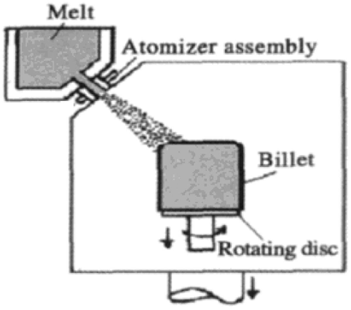
Schematic drawing of spray casting process
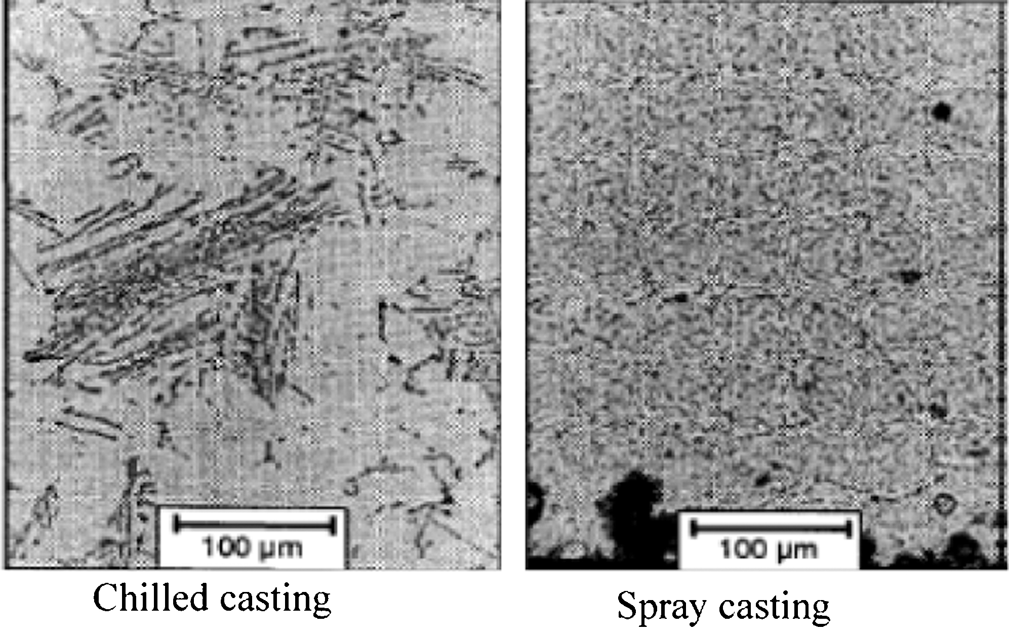
Comparison of Mg–Li alloy microstructures under different casting process
Heat treatment characteristics of Mg–Li alloys
Through heat treatment, the microstructure and mechanical properties can be optimised. Annealing processes can produce recrystallisation microstructure for as-rolled or as-extruded alloys. Solid solution and aging processes can produce favourable solid solution content and fine precipitates, which distribute evenly in alloys. All these treatments can improve the mechanical properties of the alloys.
The recrystallisation microstructure can be obtained through annealing treatment for the as-rolled or as-extruded specimens. The recrystallisation temperature of Mg–Li alloys is relatively low. The recrystallisation of Mg–4Li with α phase occurs at 360 K. A small addition of Zr will suppress the recrystallisation and the recrystallisation temperature of Mg–Li–0·2Zr is about 90 K higher than that of the Mg–4Li alloy(as shown in Fig. 9). 6 Cold-rolled plates of the alloys Mg–(5–22%)Li–2%Zn can be completely recrystallised by annealing at 573 K for 1 h. 7
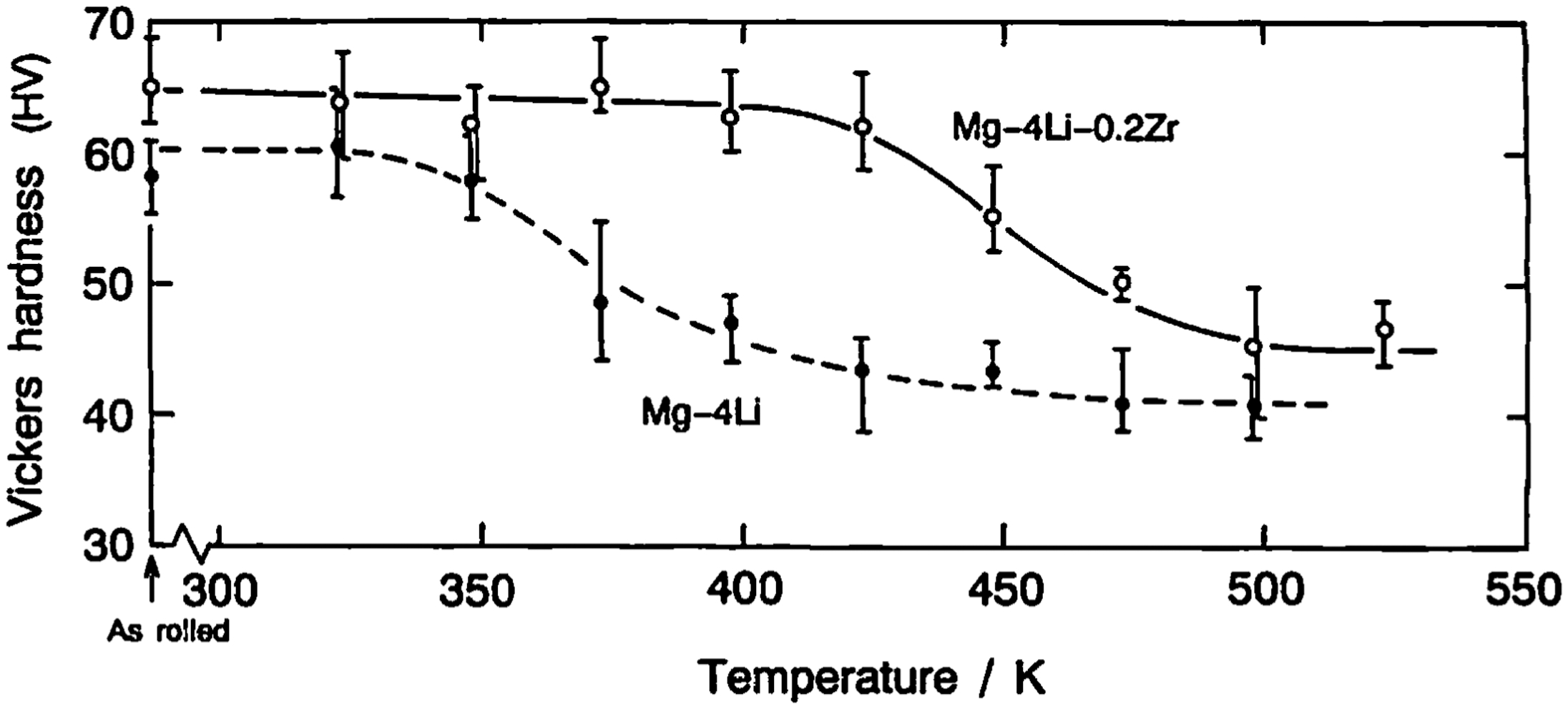
Variation in hardness of cold-rolled Mg–4Li and Mg–4Li–0·2Zr alloys with 40% reduction in thickness during isochronal annealing for 30 min
Hatta et al. 8 investigated the effects of the alloying elements (0·5 mass-%Ca, Si or Zr as a fourth alloying element) on heat treatment characteristics and tensile properties of warm-rolled specimens (Mg–20 mass-%Li–10 mass-%Al). Quenching the specimens after isothermal holding at a temperature higher than 200°C for 1 h results in an increase in hardness and strength and a decrease in elongation. This is attributed to the dissolution of aluminium into the β phase. Recrystallisation processing of the quaternary alloy containing 0·5 mass-% Si results in a fine grain structure but no obvious increase in elongation. An addition of 0·5 mass-% Ca improves the strength, whereas no sign of the improvement of elongation can be recognised. Zr does not bring any large difference in the microstructure and tensile strength as compared to the ternary alloys. As a result, there is no significant increase in ductility for the investigated alloys, although the recrystallised grains can be refined as compared to the ternary alloys.
The solid solution and aging characteristics have also been investigated by many researchers. In these studies, Mg–Li–Al and Mg–Li–Zn base alloys were mainly focused on both alloys having solid solution and age-hardening phenomena. Particularly, Mg–Li–Al base alloys exhibit a large increment of hardness by quenching and aging processes. 9–11 However, both alloys demonstrate softening phenomenon during aging. Zhong et al. 12 designed an age-hardened Mg–12Li–3Al–5Zn alloy by THERMO-CAL, and the experimental results show that this alloy has apparent age softening induced by over aging. Over aging induces softening in every age-hardened alloy, even at relatively low temperature. Metastable phase composed of four elements (Mg, Li, Al, Zn) is identified when the hardness reaches the aging peak. With an increase of the aging time (Mg, Li, Al, Zn), phase transforms to stable α phase and softening occurs.
In Mg–Li–Al alloys, the precipitation process is different with different aging parameters. Ma et al. 13 investigated the aging behaviour of Mg–8Li–1Al and Mg–11Li–3Al. The results indicated that with an increase in Li and Al content, the aging behaviour becomes more obvious. The precipitates are mainly MgAlLi2 phase (θ) that is likely to coarsen during over aging. There is no AlLi phase in the alloys. However, the phase analysis of Mg–Li–Al alloys by Wu et al. 14–17 showed that there is definitely AlLi phase in the alloys. Figure 10 shows the X-ray diffraction (XRD) pattern of Mg–8Li–3Al–Y, indicating the existence of both AlLi and θ phases.
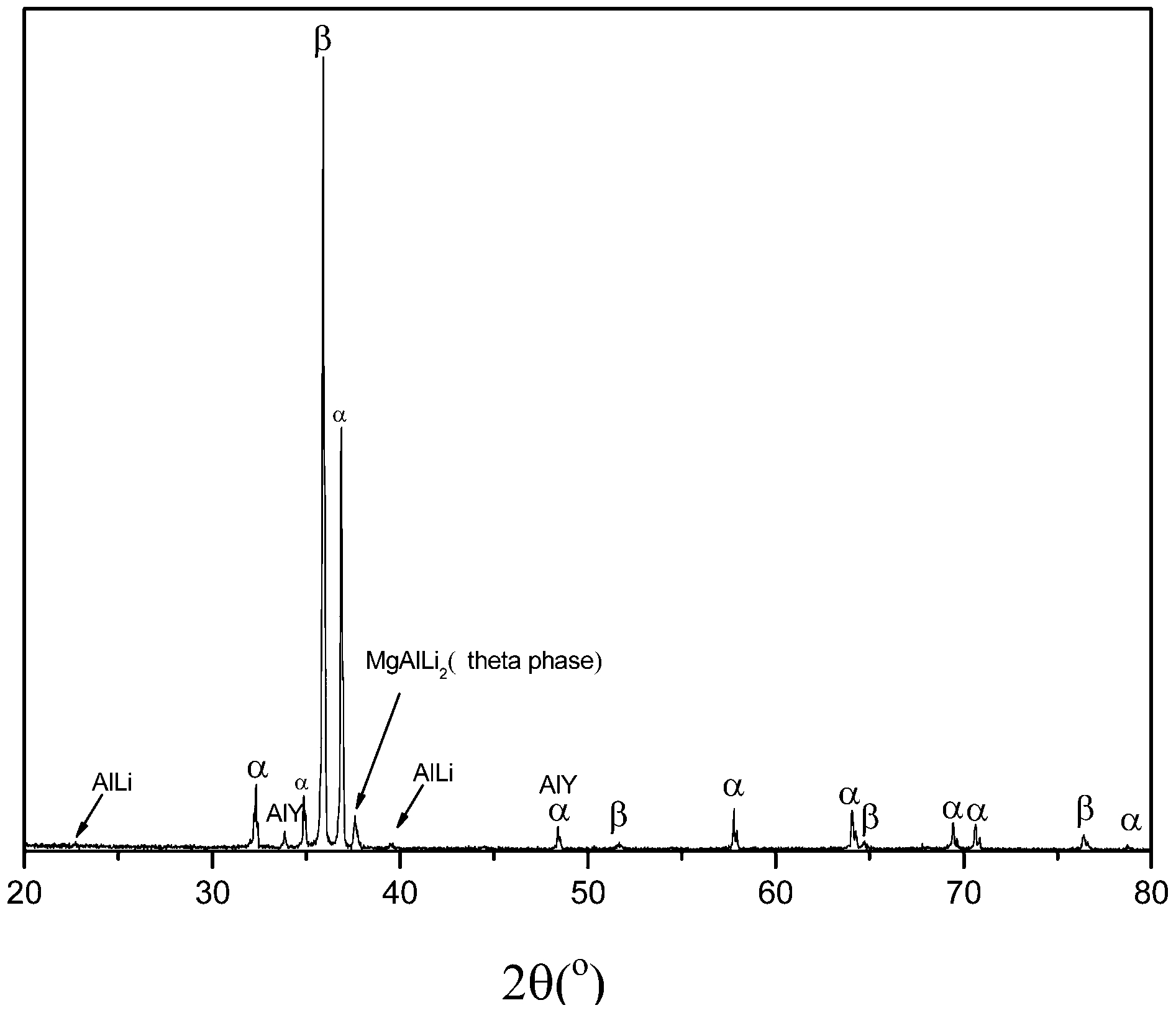
X-ray diffraction (XRD) results of the Mg–8Li–3Al–Y
Alamo and Banchik studied the Mg–31 at-%Li–1 at-%Al alloy subjected to different heat treatments, and also suggested that AlLi is a stable phase at room temperature. AlLi precipitation is only produced for very slow cooling rates. Phase transformations for specimens quenched and then aged can be summarised as follows:
18


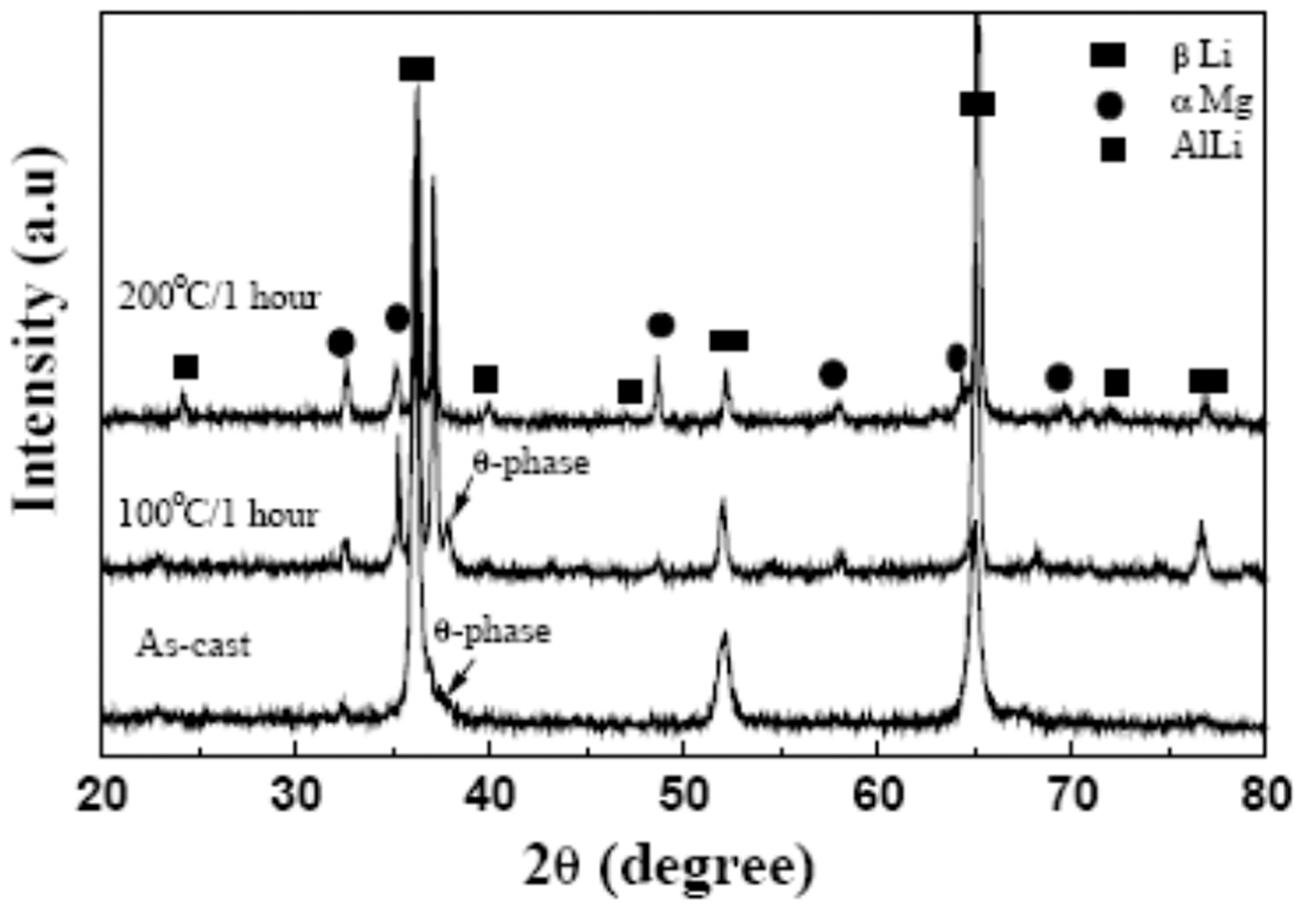
Song et al. 19 investigated the aging behaviour of Mg–12Li–0·03Be–(1,3)Al. After 24 h room temperature aging for the initial post-cast specimen (steel mould with a diameter of 10 mm), an obvious hardening occurs in Mg–12Li–0·03Be–1Al, while no hardening occurs in Mg–12Li–0·03Be–3Al. This indicates that rapid solidification retards the precipitation of θ phase in Mg–12Li–0·03Be–1Al. With a high Al content, the precipitation of θ phase becomes more rapid, and no age hardening exists at room temperature. After elevated-temperature aging of Mg–12Li–0·03Be–3Al, the hardness softening is apparent because of the decomposition of θ to α and AlLi, as shown in Fig. 11.
Variations of X-ray diffraction (XRD) patterns of cast Mg–12Li–3Al–0·03Be alloy with temperature
The effects of Al on the precipitation of θ in the as-cast Mg–Li alloys were also verified by Qu et al. 20 Mg–9Li–3Al (LA93) is composed of α, β and AlLi, while Mg–9Li–6Al (LA96) is composed of α, β, AlLi and θ. After solution treatment, AlLi phase is completely dissolved into the matrix, while the θ phase in LA96 alloy cannot be fully dissociated in the matrix. The hardness of LA96 alloy is higher than that of the LA93 alloy. During the room temperature aging process, the hardness of LA93 increases; however, it decreases from 24 to 48 h. As for LA96, the hardness of the aging state is lower than that of the solution state, and with the aging time prolonging, it decreases further. This is attributed to the transformation of θ to AlLi phase, resulting in age softening.
For Mg–37·5 at-%Li–0·7 at-%Al–0·4 at-%Cu alloy after solution (723 K×3·6 ks) and aging treatment at room temperature, 353 and 413 K, respectively, age hardening can be observed, especially at room temperature (the peak hardness is 1·8 times as large as the hardness in the as-quenched state). At the as-quenched state, no precipitates are observed in the alloy, while many fine precipitates with the size of several micrometres in size are observed in the peak aged alloy at room temperature. 21 Li et al. 22 studied the solid solution of Mg–5Li–3Al–2Zn–2Cu alloy at 330–390°C for 5 h. The as-cast alloy contains a microstructure of α, AlLi, AlCuMg and Al2Cu. After solution heat treatment, the AlLi phase is dissolved into the matrix; however, the AlCuMg and Al2Cu phases cannot be dissolved. The addition of Cu can restrict the formation of AlLi phase and make the amount of AlCuMg and Al2Cu increase with an increase in Cu content, making the hardness of the alloy greatly improved. 23 The Mg–5Li–3Al–2Zn–1·5Cu alloy after hot extrusion plus solid solution (390°C for 5 h) possesses hardening behaviour at an aging temperature of 150°C because of the continuous and discontinuous precipitation of AlLi phases. 150°C for 14 h responds the peak hardness of 72HB occurs at 150°C for 1 h. 24
The addition of Ag has the effect of promoting the existence of θ phase in the alloy of Mg–5Li–3Al–2Zn, and retarding the formation of the AlLi phase. Accordingly, the softening in response to the transformation of θ to AlLi can be avoided. Figures 12 and 13 show the microstructure and aging hardness curves of the alloys with different Ag content. 25
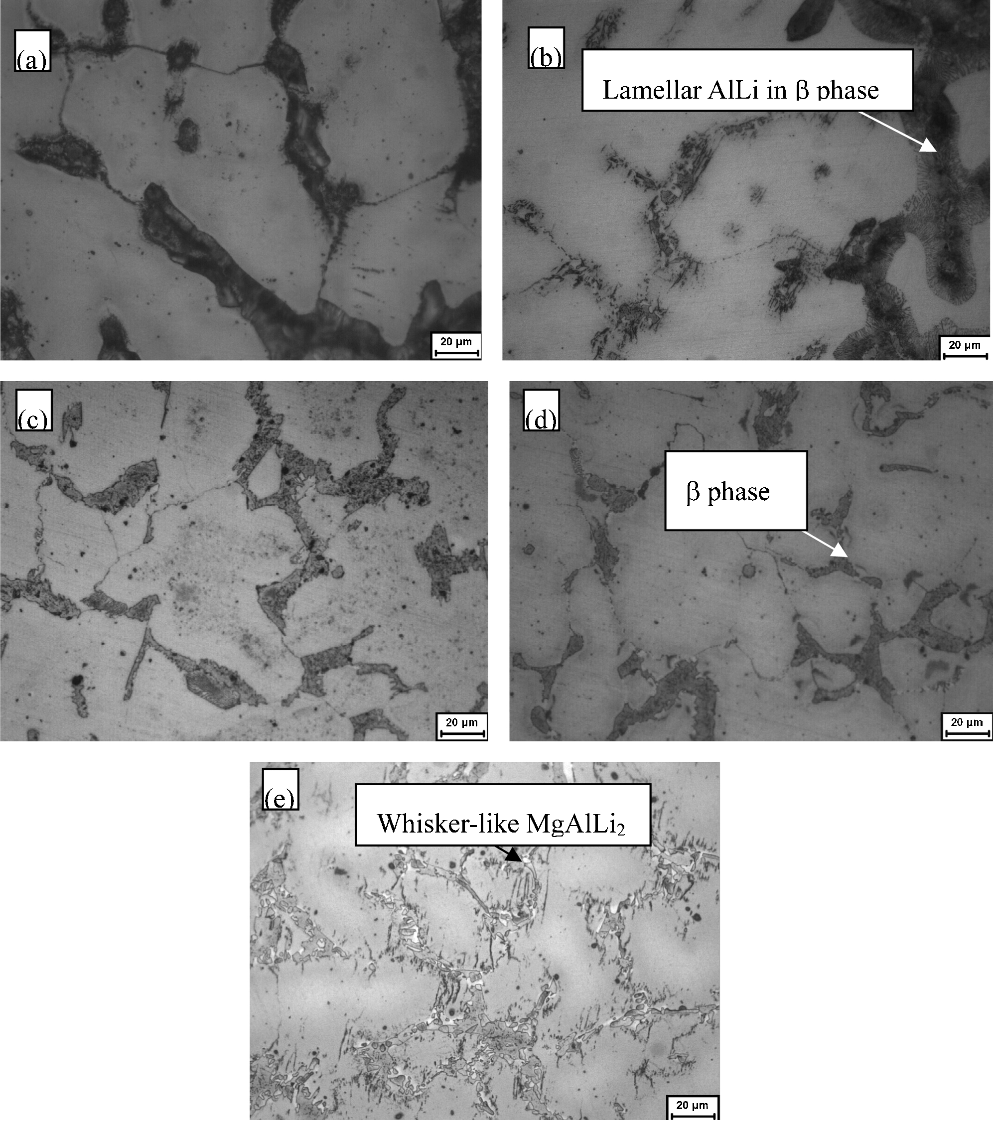
Optical microstructure of as-cast Mg–5Li–3Al–2Zn–xAg alloys: a x = 0; b x = 0·1; c x = 0·3; d x = 0·6; e x = 1·2
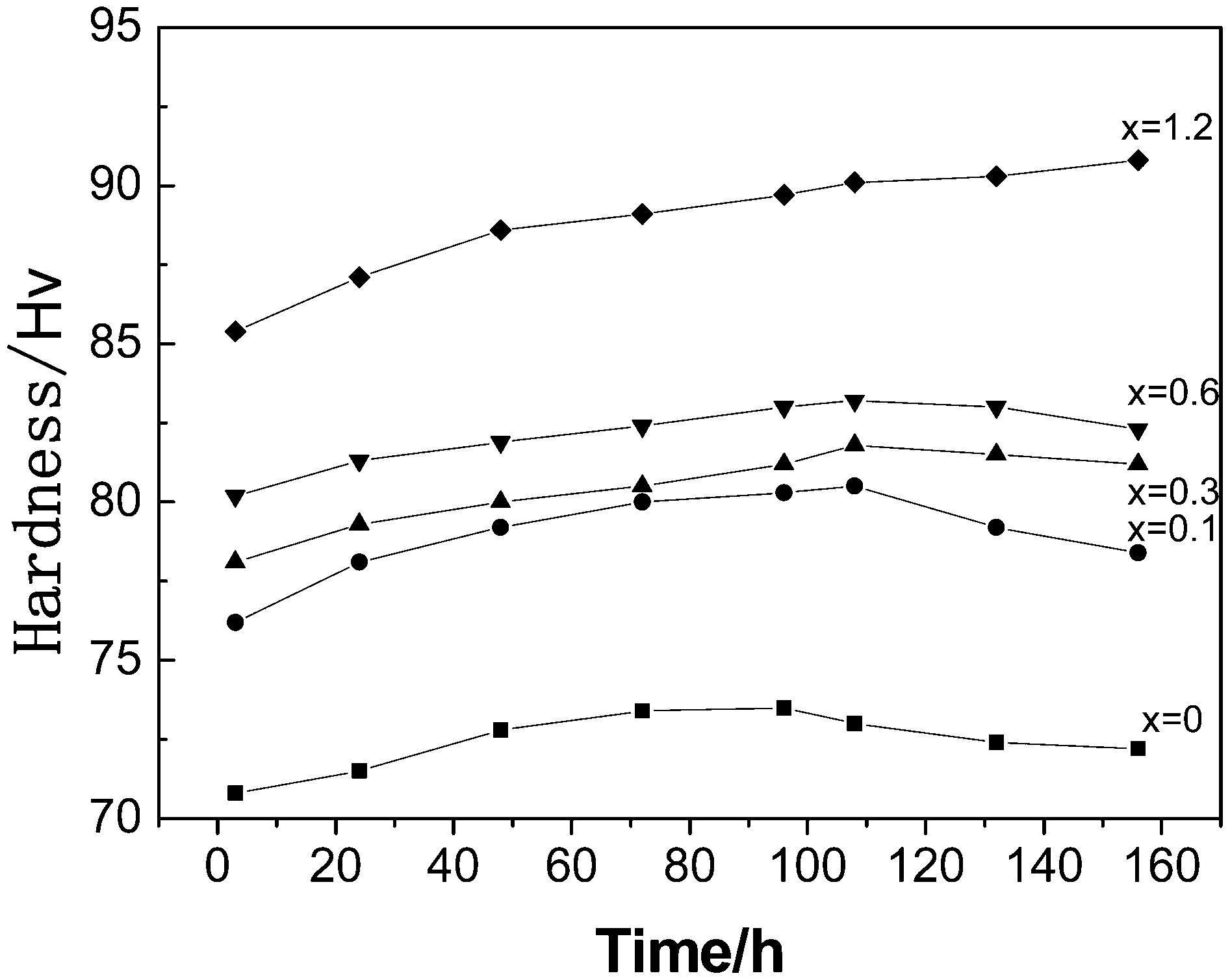
Aging behaviour curves of Mg–5Li–3Al–2Zn–xAg alloys (aging temperature is 100°C)
The addition of minor Sc in LAZ1010 improves the transformation from θ to AlLi, and reducing the softening temperature, as shown in Fig. 14. 26 The cooling rate of quenching also significantly influences the mechanical properties. For instance, quenching the Mg–7Li–14Zn–1·6Ag–1Nd–2Ce into water after solid solution treatment at 370°C for 30 min, the hardness is lower than quenching into liquid nitrogen. During the aging process, the alloy quenched in water shows age hardening with the peak hardness at 24 h, while the alloy quenched in liquid nitrogen shows softening. When aging at 38°C, the hardness of the alloy quenched in water is higher than that of the alloy quenched in liquid nitrogen. While at 75°C, throughout the aging process, the hardness of the alloy quenched in water is lower than that of the alloy quenched in liquid nitrogen. The hardening and the softening of the Mg–7Li–14Zn ternary alloy are primarily determined by the precipitation and decomposition of MgLi2Zn. The new phases induced by the additions of La, Ce, Nd, and Ag are not only strengthening phases themselves but also cut down the precipitation rate of MgLi2Zn, especially inhibit the decomposition of the phase. 27 The Mg–(4–13)Li–(4–5)Zn alloys with α or β single phase, or with (α+β) dual phases have been investigated by Yamamoto et al. 28 The results indicate that, in the alloys with single α phase, age hardening is attributed to the precipitation of the stable MgLiZn phase with the orientation relationships of [1010] α//[110]MgLiZn and (0001) α//(111)MgLiZn. In the alloys with (α+β) phases, during aging, the precipitation of α phase together with the metastable MgLi2Zn phase occurs at grain boundaries between α and β phases, and also β and β grains. The orientation relationships are (0001) α//(011)MgLi2Zn and [0110] α//[111]MgLi2Zn. The age hardening in the β alloy is caused by the precipitation of the MgLiZn phase and over aging is attributed to the precipitation of the α and MgLi2Zn phases.
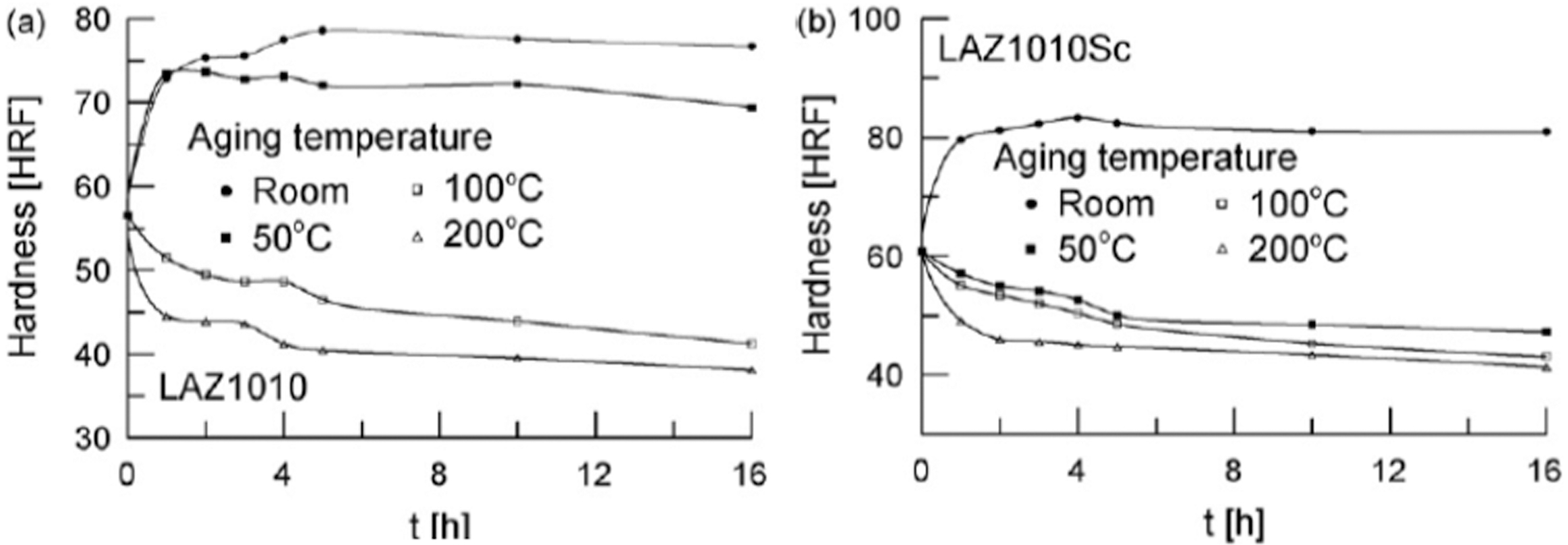
Effects of temperature and soaking time on the hardness during age heat treatments: a LAZ1010 alloy; b LAZ1010Sc alloy
Plastic deformation
Formability
In Mg–Li alloys, the BCC β phase with a preferred orientation can show anisotropic behaviour, but this is less pronounced when compared with a hexagonal close packed (hcp) α phase with a similar degree of texture. The asymmetry of the hcp α phase will exacerbate the effects of texture.
In Mg–Li–Al alloys, the hexagonal magnesium-rich solid solution α phase exhibits a comparatively high flow stress and low formability, whereas the BCC lithium crystal β phase is soft and ductile. The intermetallic AlLi phase (ordered B2 structure) is macroscopically not deformable and increases the flow stress by dispersion strengthening. A higher volume fraction of the AlLi phase causes microcracks during deformation. The ductility increases by increasing amounts of the eutectic constituents (α phase plus β phase). The optimal combination of volume fractions of the α, β and AlLi phases enables an increase in strength with sufficient ductility. 29
Wu et al.
30,31
compared the mechanical and anisotropic behaviour between LZ60 and LZ90. With a low average n value of approximately 0·159, LZ60 did not exhibit good ability to resist plastic instability during tension. The r value of it is not large enough to give good drawability and the large negative value of Δr results in serious ear formation during the drawing process. Therefore, cold-rolled LZ60 thin sheet did not exhibit good stretchability and drawability at room temperature. As for LZ90 alloy, it presents excellent ductility even at room temperature. Thus, the formability is better than that of LZ60 alloy. Although LZ90 exhibited excellent ductility at room temperature, the strength level is somewhat inferior to that of LZ60 alloy, and the stretchability is not much superior to LZ60 because of its rather small n value. The 


Forming limit diagrams of LZ90 sheet at various temperatures
Trojanova et al. 33 studied the compression mechanical properties of three alloys Mg–4Li, LA43 and LA45 at temperatures between 25 and 200°C. Compared with LA43 and LA45, Mg–4Li alloy depends significantly on the testing temperature. Above a certain temperature, softening processes influence the course of the work-hardening curve. Increasing the activity of softening processes with increasing temperature causes differences in the deformation behaviour. Cross-slip and climb of dislocations may be responsible for the observed softening. As for LA43 and LA45, dynamic strain aging causes the post-stress relaxation (SR) effect the flow stress at the beginning of plastic deformation after SR is higher than that at the beginning of the SR. The dynamic strain aging is because of the migration of dissolved Li and Al atoms towards dislocations. 34
Takuda et al. 35,36 investigated the deformation behaviour of Mg–8·5Li–1Zn alloy sheet (a thickness of 0·6 mm after warm rolling with a total reduction ratio of 85%) at a different strain rate. Uniaxial tension tests were carried out at room temperature for various strain rates between 1·4×10−5 and 8·3×10−2 s−1. Results show that the sheet has strain-rate sensitivity even at room temperature with a strain-rate sensitivity exponent m of 0·064. The sheet has sufficiently high formability at comparatively low strain rates. The maximum elongation reaches 100%. At high strain rates, the grains are divided into fine subgrains without any obvious textural change. At low strain rates, the orientation of the texture changes during the tension tests, especially in the β phase, and the grains are elongated in the tensile direction. In cylindrical deep drawing, bore expanding and Erichsen tests for the alloy show that the limiting drawing ratio, the bore-expanding ratio and the Erichsen value are 2·2, 0·8 and 9·0 mm, respectively. It is found that the good formability of the alloy is attributed to the high strain-rate sensitivity exponent.
Comparing the formabilities of Mg–6Li–1Zn, Mg–9·5Li–1Zn and Mg–12Li–1Zn, the ductility of Mg–6Li–1Zn is inferior to that of Mg–9·5Li–1Zn and Mg–12Li–1Zn. The relationships between the stress and the strain rate in log–log scale for the three alloys are shown in Fig. 16. The strain-rate sensitivity exponent m for Mg–6Li–1Zn is small and keeps a constant value of 0·02. The m values for Mg–9·5Li–1Zn and Mg–12Li–1Zn do not keep a constant value with an increase of strain rate. The m values for Mg–9·5Li–1Zn and Mg–12Li–1Zn are 0·12 and 0·14 at lower strain rates, and are 0·05 and 0·06 at higher strain rates, respectively. The m values for Mg–9·5Li–1Zn and Mg–12Li–1Zn are obviously higher than that for Mg–6Li–1Zn, which induces better ductility of Mg–9·5Li–1Zn and Mg–12Li–1Zn than that of Mg–6Li–1Zn. 37
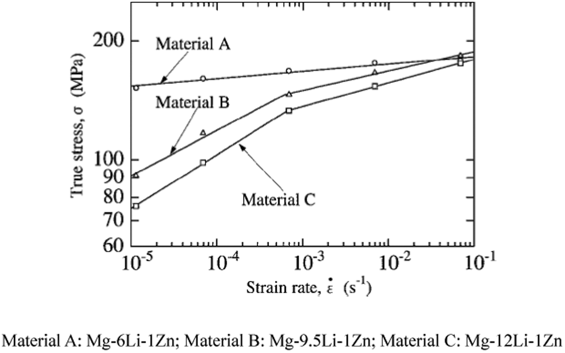
Relationships between true stress and strain rate in log–log scale for a strain of 0·1
Prasad et al. 38,39 compared the processing map for hot working of hot-rolled Mg–11·5Li–1·5Al and Mg–11·5Li–1·5Al–0·15Zr. Hot-rolled Mg–11·5Li–1·5Al and Mg–11·5Li–1·5Al–0·15Zr alloys were hot compressed in a temperature range of 200–450°C and strain rate range of 0·001–100 s−1. The map of Mg–11·5Li–1·5Al exhibits two domains, a peak efficiency of about 62% occurring at 450°C and 0·001 s−1 and a peak efficiency of about 58% occurring at 300°C and 0·001 s−1, respectively. In the domain at 450°C and 0·001 s−1, intergranular cracking exists in the microstructure, which is accordingly not a safe domain for processing. In the domain at 300°C and 0·001 s−1, the apparent activation energy for hot deformation is 110 kJ mol−1 and a very high tensile ductility is obtained. Therefore, this domain is identified to represent superplastic deformation. 40 For Mg–11·5Li–1·5Al–0·15Zr alloy, the map exhibits a single domain with a peak efficiency of 53% occurring at 350°C and 0·001 s−1. This domain represents dynamic recrystallisation (DRX). Unlike in Zr-free alloy (Mg–11·5Li–1·5Al), which exhibits only superplasticity, the Al3Zr particles in the alloy help in nucleating DRX and in refining the grains. The alloy exhibits flow instabilities at temperatures higher than 350°C and strain rates higher than 10 s−1.
Superplasticity
Superplasticity is the ability of materials to exhibit large elongations, typically several hundred per cent, at elevated temperatures and slow strain rates. It has been reported that Mg–Li base alloys in the eutectic composition range, with their microstructure consisting of two phases of hexagonal α phase and centred cubic β phase, can produce superplasticity under appropriate thermo-mechanical processing and testing conditions. 41–45 Superplasticity can improve the forming performance of magnesium–lithium alloys.
Cao et al. 46 prepared Mg–7·83Li and Mg–8·42Li alloys. The alloys were hot rolled, warm rolled and cold rolled with four passes, two passes and two passes, respectively. The total reduction was 92·5% (from the thickness of 20 to 1·5 mm). Then, the alloy was annealed in a nitrate bath at 648 K for 30 min. An average grain size of 3·48 μm was obtained in the alloys. The superplasticity tensile curves for the alloys are shown in Fig. 17. The maximum superplasticities of 850 and 920% were obtained in Mg–7·83Li and Mg–8·42Li alloys at 573 K and at an initial strain rate of 1·67×10−3 s−1 and at an initial strain rate of 5×10⁻⁴ s−1, respectively. After the superplastic deformation at 573 K, the grains of Mg–7·83Li alloy grow. The grains maintain the characteristics of equiaxial ones after large deformation, indicating that grain boundary sliding (GBS) is the dominant deformation mechanism. Different atomic mobilities of Mg, Li, α and β phases and different Gibbs free energies of α and β phases contribute to the obvious grain growth. Lattice diffusion is the grain growth mechanism. The stress exponent n, grain size exponent p and activation energy Q were calculated experimentally to be 2·1–2·3, 1·9 and 107 kJ mol−1, which are close to the theoretical 2, 2 and 112 kJ mol−1, lattice diffusion activation energies, indicating that the dominant deformation mechanism is GBS accommodated by slip controlled by lattice diffusion.
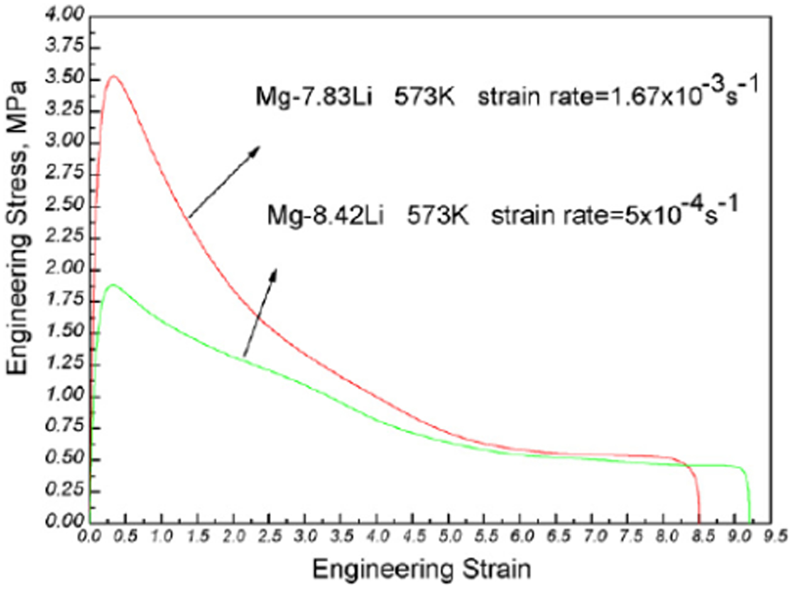
The nominal stress versus nominal strain curves of superplastic deformation in Mg–7·83Li and Mg–8·42Li alloys
Mg–8·5Li alloy after high ratio (100∶1) extrusion at 623 K possesses good superplasticity (a maximum elongation of more than 500%) at high strain rate, 1×10⁻² s−1, at 623 K. 47 The strain-rate sensitivity exponent, m value, is about 0·40 at 623–673 K at strain rates ranging from 10−3 to 10−1 s−1. The apparent activation energy for the superplastic deformation at 573–673 K with m = 0·4 is calculated to be about 80 kJ mol−1, revealing that the dominant deformation mechanism in this alloy is still GBS. Therefore, GBS and DRX during superplastic flow should be responsible for the superplastic characteristics observed in the alloys.
Mg–8·5Li–1Zn and Mg–8·5Li–3Zn alloys after high ratio (100∶1) extrusion at 623 K also possess high strain-rate superplasticity because the high ratio extrusion is effective to induce DRX in the alloys, leading to grain refinement. 48 Mg–8·5Li–1Zn alloy shows a high elongation of about 400% at 623 K at a strain rate of 1·1×10−2 s−1, and the Mg–8·5Li–3Zn alloy demonstrates a maximum elongation of more than 540% at 623 K at a strain rate of 1·18×10−2 s−1. At the examined temperatures of 573–673 K within the m value around 0·48 range, the activation energy for superplastic flow in Mg–8·5Li–1Zn and Mg–8·5Li–3Zn alloys is about 86 and 79 kJ/mole, respectively, indicating that the dominant superplastic deformation mechanism in the two alloys is GBS controlled by grain boundary diffusion.
Mg–11Li–3Zn alloy after rolling a total reduction of 94%, with a final thickness of 1·2 mm, possesses quasi-superplasticity with a maximum elongation of 200% at a temperature of 573 K and strain rate of 1·67×10−2 s−1. 49 During the superplastic tensile deformation, DRX occurs causing grain refinement, corresponding to an average grain size from 27 to 9 μm. The stress exponent is 4·4 and the activation energy is 112·6 kJ mol−1. The superplastic deformation mechanism is dislocation climb controlled by lattice diffusion. A rolled sheet with a thickness of 0·6 mm and a composition of Mg–9·5%Li–1·0Zn exhibits a quasi-superplastic behaviour with a maximum elongation of 290% at 523 K with an initial strain rate of 1·0×10−4 s−1. 50 The experiments give a strain-rate sensitivity of ∼0·33 and an activation energy of ∼92 kJ mol−1. Measurements of the shapes and sizes of the internal cavities produced during superplastic deformation reveal a transition with increasing strain from cavity growth by diffusion to growth controlled by plastic flow in the surrounding crystalline matrix.
Superplastic deformation has an influence on the mechanical properties of Mg–Li base alloys. Kaibyshev et al. investigated the influence of superplastic deformation on the alloys of IMV-2 and MA21. 51,52 Superplastic deformation at high strain rates leads to high tensile strengths and yield points. The alloys possess highly stable mechanical properties because of the highly homogeneous structure after superplastic deformation.
Superplastic deformation also affects the microstructure of Mg–Li alloys. The as-cast and thermo-mechanically processed Mg–8Li alloy possesses a maximum elongation of about 300% under suitable superplastic conditions. During superplastic deformation, needle-like α phase changes to an equiaxial shape, and the m value of 0·2 at the initial period correspondingly increases during the deformation. Twinning is observed in the α phase at the initial stage of superplastic deformation. The α grains are found to grow during the deformation, while the refining of β grains takes place. 53 The Mg–8·4Li alloy after rolling with a thickness of 2 mm possesses an elongation of 920% at 573 K at an initial strain rate of 5×10⁻⁴ s−1 with a strain-rate sensitivity exponent of 0·64. 54 The equiaxial fine grains and nearly 50/50 ratio of two phases α/β are responsible for the larger superplastic elongation. The average grain sizes at tensile specimen gauge length section before and after superplastic tension and at grip section are 7·5, 31·7 and 20 μm, respectively. This indicates that the superplastic deformation induces grain growth, and static grain growth occurs during the deformation at this temperature. The Mg–8Li alloy after being hot rolled to 3 mm thick at 623 K, and cold rolled to 1·5 mm thick with intermediate annealing temperature, exhibits a maximum elongation of 960% at a temperature of 573 K, with an initial strain rate of 5×10⁻⁴ s−1. 55 During superplastic deformation, DRX takes place. Grain growth and cavity nucleation at α phase grain boundaries can also be observed. It is postulated that the continuous introduction of lattice dislocations into the phase interfaces contributes to the superplasticity of the alloy.
Furui et al. 56 compared the ductilities of Mg–8Li alloys processed by different thermo-mechanical procedures. Results show that Mg–8Li alloy possesses very limited ductility in the as-cast condition and only moderate ductility after rolling. However, excellent superplastic properties are achieved at a testing temperature of 473 K by extruding the cast alloy, and the superplastic properties are further improved by extruding and processing through two passes using equal-channel angular pressing (ECAP), as shown in Fig. 18. The Mg–8Li alloy processed by deformation combining the extrusion and ECAP possesses a maximum elongation of 970% at a temperature of 473 K, and with a strain rate of 1·0×10−4 s−1. 57 During superplastic deformation, the frequency of high angle boundaries, defined as above 15° misorientation, increases with increasing the elongation to failure in order to advance DRX. Cavities form at the boundaries between α and β phases from the elongations of about 600%. The area fraction of cavities in the cast+extrude+ECAP condition was smaller than in the cast+extrude condition. The measured strain-rate sensitivity was of the order of 0·6. The activation energy for superplastic flow was essentially equal to the value for grain boundary diffusion of Mg. 58 The addition of Zr in Mg–8Li alloy induces the maximum elongation increase because of the finer grain structure before loading and suppression of dislocation processes by solute atoms of Zr, which results in both uniform deformation and DRX. 59
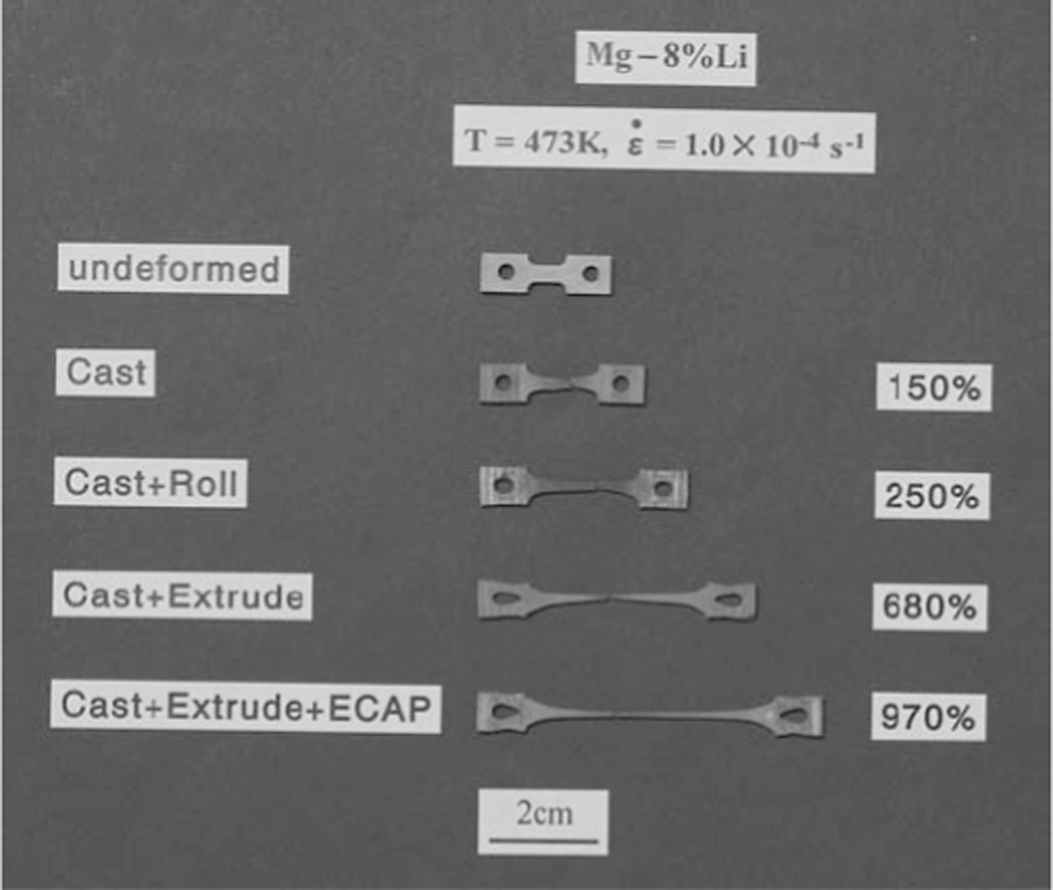
Appearance of specimens processed by the different routes and subsequently tested in tension to failure at 473 K using the strain rate of 1·0×10−4 s−1
Qu et al. 60 prepared Mg–8Li alloy with the methods of casting and extrusion. The diameters of the specimen before and after extrusion were 55 and 15 mm, respectively. The extrusion temperature was 553 K. The grain size of the alloy was less than 10 μm. The superplastic property of the alloy was somewhat poor. Only at the temperature larger than 523 K and strain rate of less than 2×10⁻⁴ s−1 the alloy exhibits superplasticity. A maximum elongation of 164·5% was obtained at a temperature of 563 K with an initial strain rate of 5×10⁻⁵ s−1. The processes of formation and merging of cavitations are favourable for the superplastic behaviour of the alloy. When the size of cavitation is large enough, tensile failure occurs.
Yoshida et al. 61,62 prepared Mg–Li–Zn alloys with repetitive ECAP processing, which possess low temperature superplasticity because of the refining of both the phases of α and β, and spheroidising of the α phase. The elongation of the alloy at 373 K, which is lower than T m/2, reaches about 400% with a strain rate of 1×10⁻⁴ s−1. The alloy has a relatively high strain-rate sensitivity exponent of about 0·4. During superplastic deformation, the DRX and particle precipitation occur in both α and β phases. An increase of grain boundary area through the fine recrystallised grains and precipitation of β phase on the recrystallised grain boundaries of the α phase contributes to GBS, resulting in the occurrence of superplasticity.
Mg–8Li–2Zn alloy processed by two-pass extrusion (553 K, from Φ106 to Φ50 mm, then from Φ50 mm to 30×3 mm) exhibits superplasticity at low temperature (an elongation of 120% at a temperature of 423 K) 63 and at high strain rate (an elongation of 279% at an initial strain rate of 1×10⁻² s−1). 64 This alloy has the largest elongation of 758% at 563 K with a strain rate of 1·5×10−4 s−1. 65 During superplastic deformation, the strain-rate sensitivity is about 0·55 and the activation energy is about 89·4–99·24 kJ mol−1, showing that the deformation is grain-boundary sliding controlled by grain-boundary diffusion. Coalescence and interlinkage of cavities is the reason for tensile failure.
Deformation texture
Deformation texture of alloys not only affects the subsequent deforming processes but also causes anisotropic mechanical properties in the alloys. Accordingly, texture in deformed alloys is a very important factor affecting properties of the alloys.
Mg based alloys are typically hcp structural materials. Compared with face-centred and body-centred cubic materials, hcp metals exhibit a wider variety of deformation textures. The distinct textures depend on the combined effects of c/a ratio and the fact that the plastic deformation occurs through different slip systems and/or twinning modes. 66
The addition of Li and other alloying elements affects the texture of Mg based alloys. Agnew et al. 67 investigated the compression textures of as-rolled Mg–(0–5)Li alloys. Results show that, when the addition of Li is less than 5 wt-%, there are only subtle differences in the compression textures of magnesium. However, the plane strain compression textures of the alloys show an increasing tendency for the basal poles to rotate away from the ‘normal direction’ towards the ‘rolling direction’. This can be attributed to the increased activity of the non-basal <c+a> slip mode, which can accommodate c-axis compression within individual grains, causing improved compressive ductility compared to pure magnesium. Betsofen et al. 68 also found that the lithium alloying causes the formation of a prismatic rolling texture in the alloys as a result of the phase transformation of the lithium-based bcc phase into the magnesium-based hexagonal close-packed phase, which obeys the Burgers orientation relationships.
Al-Samman compared the deformation behaviour of Mg–4Li and AZ31 alloys.
69
With respect to the room temperature formability examined in cold rolling and channel-die compression experiments, Mg–4Li alloy demonstrates a remarkable ductility enhancement over AZ31 alloy. During cold rolling, a total thickness reduction of 86% is easily achieved with no signs of cracks or mechanical instabilities. Correspondingly, AZ31 alloy exhibited a typical brittle response and failed at a total thickness reduction of 26% despite low reduction per each rolling pass (0·1 mm/pass), as shown in Fig. 19. The addition of Li seems to result in a congenerous deformation behaviour and texture evolution irrespective of the starting texture, which is completely different from that observed in AZ31, where the stress–strain mechanical response (flow curves) and texture evolution are strongly dependent on the starting texture. After cold rolling, Mg–4Li shows a basal texture with central peak intensity splitting, which is rotated towards the rolling direction. At room temperature, the addition of Li into magnesium seems to enhance the activation of <c+a>-pyramidal slip. With an increase of deformation temperature, the orientations seem to spread along TD forming an RD 
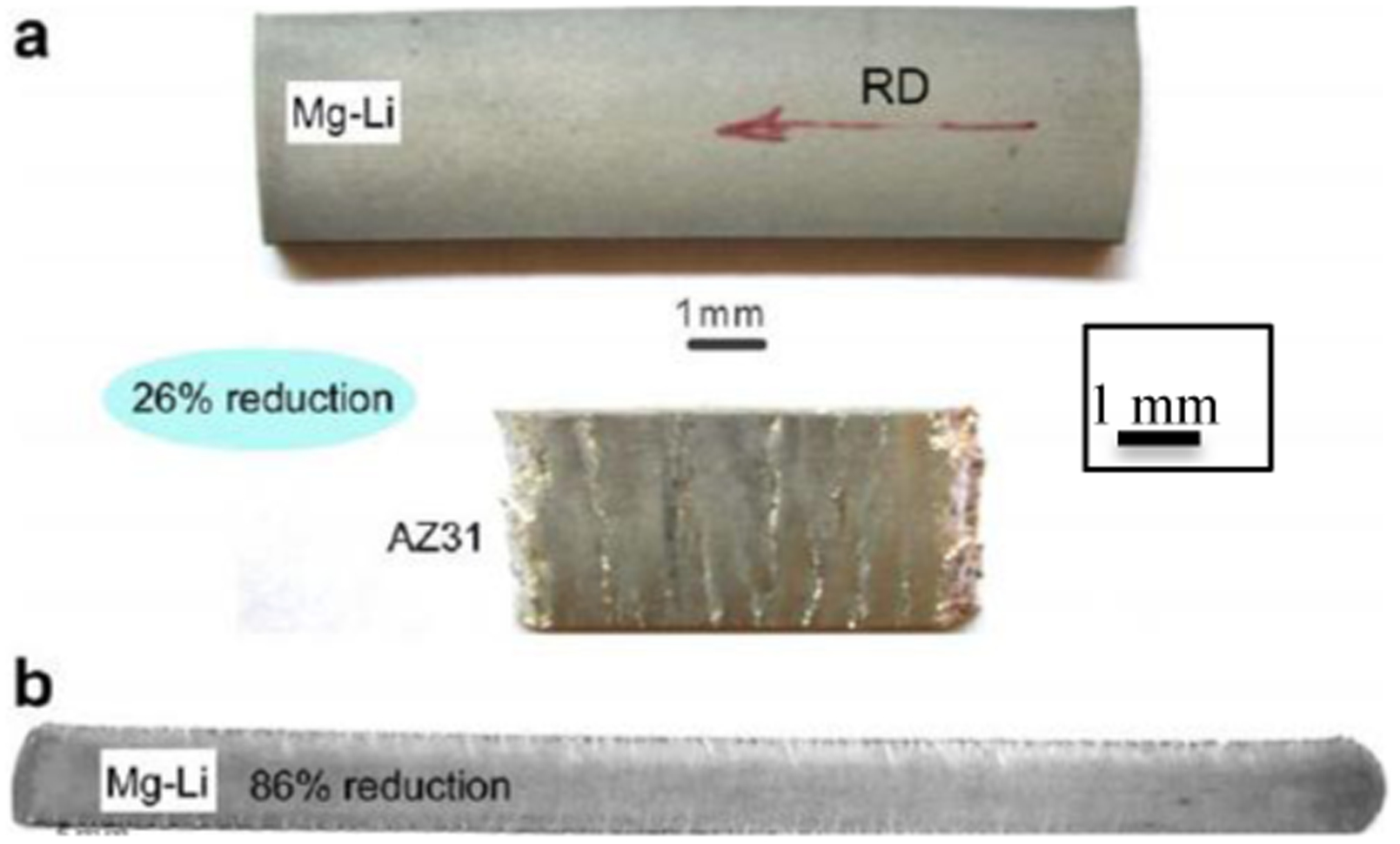
Cold-rolling behaviour comparison between Mg–4Li and AZ31 alloys
Liu et al. 70 investigated the microstructure and texture of Mg–3·3Li after ECAP with two different routes, A and Bc, respectively. Results show that two quite different and strong textures are formed in the alloy after two ECAP processes with the routes A and Bc. Recrystallisation occurs during both the ECAP processes, but the extent of recrystallisation is different for route A and Bc. ECAP can not only refine the grain size but also modify the texture type of the alloy. The combined effect of grain refinement and texture modification caused by ECAP can improve the strength and ductility of the alloy simultaneously.
Kumar et al. 71 studied the effect of hot-rolling process on the texture evolution of Mg–9%Li–5%Al–3%Sn–1%Zn (LATZ9531). The rolling textures for as-cast and as-rolled LATZ9531 are shown in Fig. 20 in terms of basal (0001) pole figures. It was found that strong basal texture is absent in the as-cast alloy (Fig. 20a ), and significant texture evolves after hot rolling at ∼573 K (Fig. 20b ). Random texture can be observed in the case of the as-cast alloy, as shown in Fig. 20a . On the other hand, the tilt of the basal-pole texture from the normal direction towards the transverse direction is observed in the as-rolled alloy. This strongly suggests that the sample is less prone to develop a basal texture, and the textures show even much weaker peak intensity, which is beneficial for further deformation because of availability of non-basal slip planes. The splitting of the basal poles about TD is attributed to an increased activity of the non-basal slip mode during compressive deformation. Central basal pole splitting along the sheet rolling direction is commonly observed during hot deformation of wrought commercial magnesium alloys such as AZ31; however, the splitting along the transverse direction is evident in the basal texture of the hot-rolled LATZ9531, which is attributed to the higher lithium and aluminium content, lowering c/a ratio.
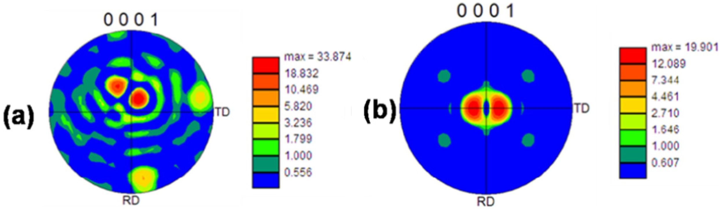
The texture in terms of (0001) pole figures for as-cast and as-rolled LATZ9531 alloys: a as-cast; b as-rolled
Wu et al.
72
investigated the effects of the combined addition of Y and Nd on the room temperature compression texture of Mg–5Li–3Al–2Zn (LAZ532). The ODF sections for the alloys of LAZ532 and LAZ532–1·2Y–0·8Nd under different compression strains show that, when the strain is larger than 0·04, basal texture exists in LAZ532, while in LAZ532–1·2Y–0·8Nd, prismatic texture exists. The EBSD (Electron Backscattered Diffraction) analysis for LAZ532–1·2Y–0·8Nd at a strain of 0·04, as shown in Fig. 21, shows that some 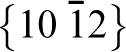
EBSD analysis of Mg–5Li–3Al–2Zn–1·2Y–0·8Nd compression in room temperature: a orientation image map; b pole figure of (0001); c inverse pole figure
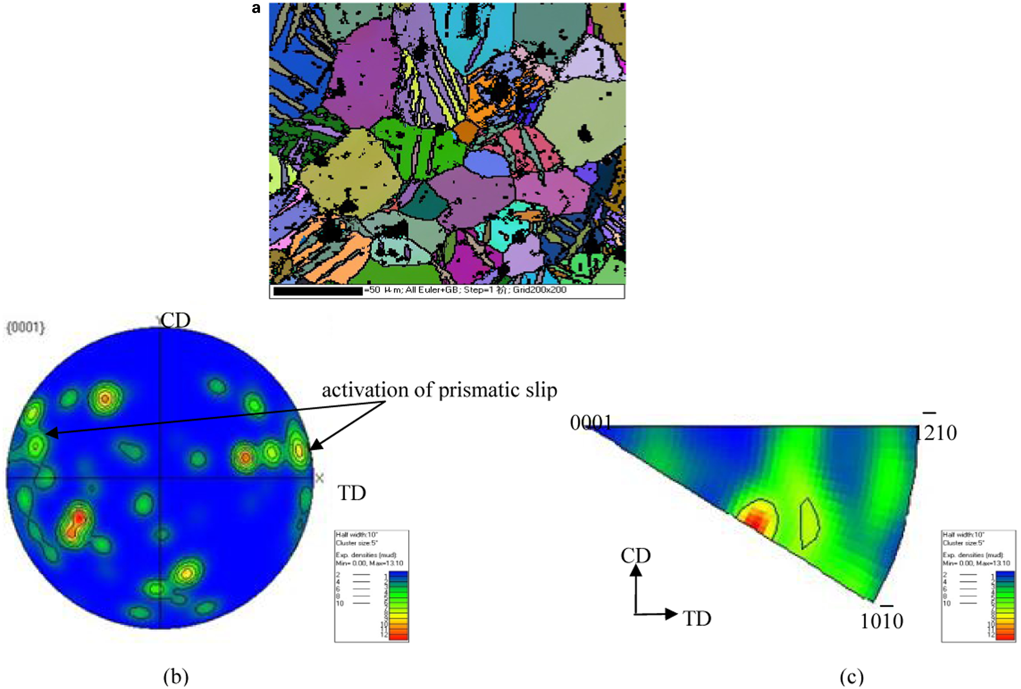
Compression stress–strain curves of the two alloys
Mg–Li base composite materials
Mg–Li base alloys reinforced with ceramic materials or intermetallics possess some advanced properties: 73
Increased apparent limit of elasticity, stiffness, tensile and fatigue strength
Improved creep resistance and high temperature properties
Improved material damping
Increased wear resistance
Decreased thermal expansion
Accordingly, Mg–Li base alloys reinforced with various reinforcements have recently attracted considerable attention.
Al2Yp reinforced Mg–Li composite
Compared with ceramic materials, some intermetallics have high specific strength, specific stiffness and high modulus, much superior plasticity, and metallic bond characteristics. Accordingly, these intermetallics can be utilised as one of the most promising reinforcements to fabricate composites with lightweight, high tensile and good integration mechanical properties. Al2Y compound has low density (3·93 g cm−3). When compared to β–Mg–Li alloy, Al2Y compound presents interesting properties: high melting temperature, high Young’s modulus, 74 high hardness, and low coefficient of thermal expansion. Therefore, Al2Y can serve as an excellent reinforcement in Mg–Li base alloy.
When 5 wt-% Al2Y particulates (with an average size of less than 37·5 μm) are added into Mg–14Li–1Al (LA141) as a reinforcement (using stir casting with 700 rev min−1 for 30 min), they distribute homogeneously in the alloy matrix. There is a clean interface between Al2Y particles and the Mg–Li matrix, and no obvious elements diffusing to the interface. Accordingly, it is concluded that no particle/matrix interfacial reaction products exist in the Al2Yp/Mg–Li composite during the manufacturing process. The existence of the Al2Yp reinforcement significantly improves the mechanical properties of the alloy. The tensile strength, elastic modulus and hardness of the composite are higher than those of LA141 alloy by 45·3, 44·7 and 58·2%, respectively, while a good ductility property with an elongation of 7% can be maintained. 75
When 15 wt-% Al2Y particulates with a size range of 5–30 μm are added into Mg–12Li as a reinforcement in a vacuum non-consumable arc-melting furnace under an argon atmosphere, the Al2Y particulates distribute homogeneously in the alloy matrix. A clean interface is formed between the Al2Y particulates and the Mg–Li matrix. The hardness, shear strength and compression strength of the composite are higher than those of the alloy matrix by 150, 75 and 186%, respectively. 76
δ-alumina fibre reinforced Mg–Li composite
Trojanova et al. 77 prepared a series of Mg–Li based composites with the gas pressure infiltration into a fibrous perform (short alumina fibre). Matrix alloys of composites are Mg–xLi (x = 4,8,12), exhibiting the phase structure of hcp(α), bcc (β) and mixture (α+β) structures. The flow stresses of the composites are substantially higher than those of unreinforced alloy. The reinforcing effect of fibres and particles decreases with increasing temperature. The load transfer at the fibre/matrix interface and enhanced dislocation density are considered to be the most important strengthening mechanisms. Residual thermal stresses also play a significant role. There is a high probability that cross-slip and subsequent annihilation of dislocations cause softening. Local climb of dislocations in the vicinity of fibres supported by interface diffusion may also contribute to softening. When 10 vol.-% of short alumina fibre is added into Mg–8Li–xAl (x = 3,5), the strain hardening of the composite is characteristic of deformation at room temperature, as well as at 100°C. Recovery processes occur at higher temperatures. 78 Similar to that in the Mg–xLi matrix composite, the contributions for the strengthening effect of the composite is the load transfer on the fibre–matrix interface and an increase of dislocation density.
In the Mg–Li/δ-alumina fibre composite, the formation of the interfacial bond in alumina fibre reinforced Mg-based composites is strongly promoted with lithium alloying. There are strong driving forces for redox reactions at the fibre/melt interfaces during the melt infiltration process producing Li+ that reacts immediately with adjacent alumina to form a metastable spinel-like compound δ(Li) structurally coherent with δ-Al2O3. Elemental aluminium as a byproduct of the redox alumina decomposition is dissolved in the Mg–Li matrix causing its additional alloying as demonstrated schematically below:
79,80


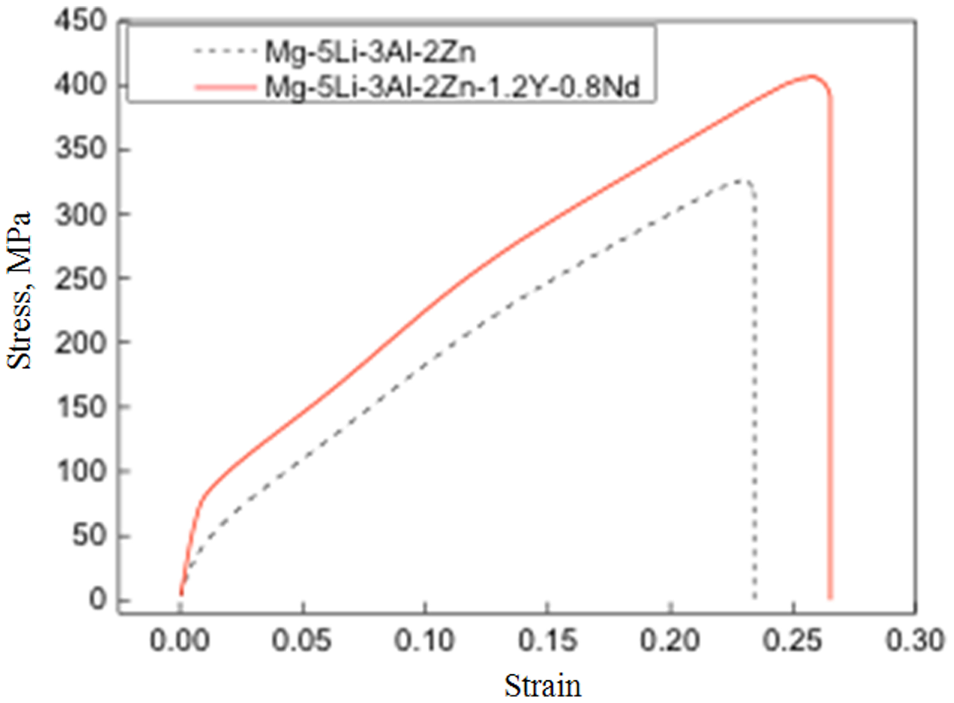
Mg–Li alloy reinforced by short δ-alumina fibre shows an anisotropy of thermal expansion. Kudela et al. 81 prepared Mg–4Li and pure Mg matrix composites reinforced by short δ-Al2O3 fibres with melt infiltration at 730°C/30 s under argon pressure (6 MPa), referred to as Mg4Li/SF and Mg/SF. Prepared composites contained 10 vol.-% fibres of mean length of ∼300 μm and mean diameter of ∼3 μm. The fibres were arranged randomly in planes parallel to each other. This gives rise to two distinct fibre configurations with fibre planes either parallel (‘in-plane’) or perpendicular (‘cross-plane’) to the axis of the composite rod (6 mm in diameter, 50 mm in length). The measurements for the coefficiency of thermal expansion (CTE) showed that the in-plane Mg/SF expands less than the in-plane Mg4Li/SF. Expansion curves of both composites were located well below those of unreinforced Mg and Mg4Li matrixes, demonstrating a thermal expansion reduction because of the fibres. In cross-plane, the CTE of Mg/SF was larger than that of Mg4Li/SF, while in in-plane, the CTE of Mg/SF was lower than that of Mg4Li/SF. The temperature dependence of CTE of Mg4Li alloy and both in-plane and cross-plane Mg4Li/SF composites is shown in Fig. 23. When the temperature is lower than 300°C, both in-plane and cross-plane CTE curves of Mg4Li/SF are less than that of Mg4Li, and the cross-plane CTE curve is higher than the in-plane CTE curve of Mg4Li/SF. When the temperature is larger than 300°C, the cross-plane CTE curve of Mg4Li/SF is higher than that of Mg4Li, and the in-plane CTE curve of Mg4Li/SF decreases with temperature.
Temperature dependence of CTE of Mg4Li alloy and both in-plane and cross-plane Mg4Li/SF composites
SiC reinforced Mg–Li composite
The enforcement of SiCw in Mg–Li binary alloys improves the damping capacity, and it is shown that the high Li content is beneficial to improvement of damping capacity, as shown in Fig. 24. 82 The high damping capacity of SiCw/MgLiAl composites is attributed to the increased interfacial defect and the higher dislocation density induced by the addition of SiCw. Compared with the Mg–Li matrix, higher tensile strength and higher modulus are obtained. Moreover, the specific strength and specific modulus are also increased. Research on the interface between SiCw and Mg–Li matrix shows that a clear interface can be obtained. SiCw connects with the matrix in (111) and forms 70·5° or 109·5° stages on the whisker surface in (111). 83
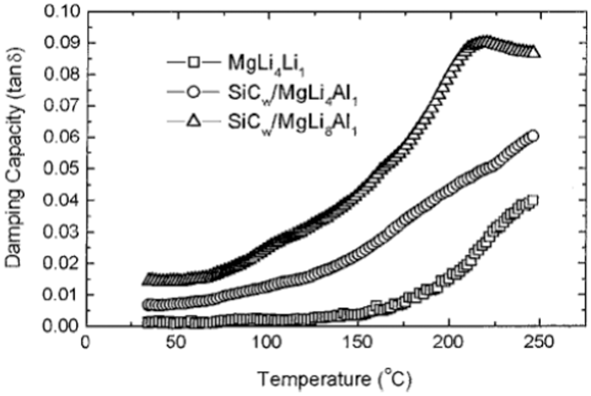
Comparison of the damping capacity for MgLi4Al1, SiCw/MgLi4Al1 and SiCw/MgLi8Al1 (ϵ = 1×10⁻⁴, f = 1 Hz)
B, B2O3 and B4C reinforced Mg–Li composite
In B particle reinforced Mg–Li base alloys, both a high strength and a high ductility can be obtained because of the existence of Li, which can counteract the negative effect of the existence of hard B particles on the ductility. 84 A high specific stiffness can also be expected because of the low density of Li element. The existence of B reinforcement in the Mg–14Li matrix is contributed to the improvement of creep behaviour at 230–280°C. The creep strength of 30 vol.-%B/Mg–14Li is increased by a factor of eight over the Mg–14Li matrix. 85
The addition of B2O3 in Mg–Li melt causes the following reaction:
86

Gonzalez-Doncel et al. 87 used the foil metallurgy method, a thermo-mechanical process based on low temperature press bonding of cold-rolled and annealed foils, to prepare a fine-grained Mg–9Li laminates and a particulate composite of Mg–9Li containing 5 wt-% B4C. As for Mg–Li base composite, this method is potentially more attractive than powder metallurgy processing because contamination is reduced as a result of the low surface-to-volume ratio in the foils. The total amount of reduction in foil thickness during cold rolling determines the final grain size of the composite alloy. The total reduction of 170∶1 corresponds to a fine grain size of 2 μm. The room temperature ductility of the composite is higher than that of the as-cast alloy by 50%, and the specific stiffness is 3·16×106 m3, about 22% above that of commercial aluminium and titanium alloys. The composite possesses superplasticity at 150–200°C with a stress exponent of 2. The flow stress in compression is about two to three times higher than in tension. This can be attributed to the greater ease of GBS in tension than in compression. The activation energy for superplastic flow is 55 kJ mol−1 and is essentially independent of the mode of testing. 88 It is postulated that superplastic flow of the Mg–9 wt-%Li–5 wt-%B4C particulate composite occurs by GBS controlled by grain boundary diffusion.
The pre-treatment of alkaline solution for B4C particles can not only reduce the agglomerates and produce uniform distribution of the B4C particles in the composite but can also enhance the wetting ability between B4C particles and Mg–Li matrix. The tensile strength of B4C/Mg–Li composite increases 21·53% compared with that without alkaline solution treatment, while the elongation decreases by only 2·29%. 89
Wu et al. 90 prepared B4Cp/Mg–8Li–1Zn and B4Cp/Mg–8Li–1Al–1Y composites using hot-extrusion solid-state composite processing. With the optimised parameters, the deformation effects and the migration of α phase between the foils were improved, and the amount and size of foil gaps decreased. The bonding force between foils was improved, and the oxidation of foils was lowered. The results of tensile test showed that the strengths of the B4Cp/Mg–8Li–1Zn and B4Cp/Mg–8Li–1Al–1Y composites were increased after hot-extrusion solid-state composite processing (238 and 257·23 MPa, respectively).
Steel fibre reinforced Mg–Li composite
Steel wool (bcc structure) can be used as reinforcement in Mg–Li matrix with the infiltration casting process. The use of discontinuous, chopped fibres, rather than a layered, continuous fibre preform, can somewhat improve the deformation characteristics of the composite. As for hcp/bcc Mg–4Li/27 vol.-%steel composite, it has limited formability because of the severity of internal cracking, shown in Fig. 25. 91 The strength of the Mg–4Li/27steel increases from 163 MPa as-cast to 332 MPa at a true strain of 3·9. Strengths are lower than predicted from ROM calculations. As for bcc/bcc Mg–12Li–2Nd/21vol.-% steel composite, it has a good formability (reaching a true strain of 9·2) when swaged at room temperature. The tensile strength increases from 180 to 326 MPa at a strain of 4·3. Strengths are also lower than predicted from ROM calculations because of the presence of fibres considerably larger than the average size measured stereologically. 92 The bcc/bcc material shows the potential for producing highly formable composite sheet materials by combining a ductile bcc matrix with a bcc reinforcing fibre. Figure 26 shows the different formability of Mg–4Li/27 vol.-%steel and Mg–12Li–2Nd/21vol.-%steel.
Internal cracking on hcp/bcc Mg–4Li/27 steel composite during deformation
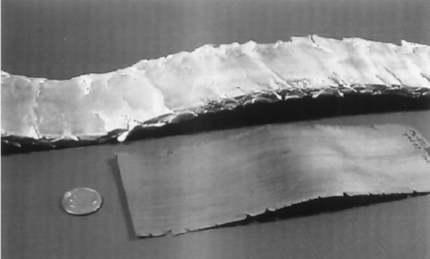
Comparison of the rolling characteristics of hcp/bcc Mg–4Li/27steel (top) and bcc/bcc Mg–12Li–2Nd/21steel (bottom)
Al/Mg–Li cladding composite
It is well known that Mg–Li alloys possess poor corrosion resistance, while Al alloys have excellent corrosion resistance because of the formation of a thermodynamically stable Al2O3 protective surface oxide scale. In addition, various surface-treatment techniques are already established industrially for Al alloys. Therefore, the cladding of Mg–Li and Al alloy plates is considered to be promising to improve the corrosion resistance of Mg–Li alloy plates.
Matsumoto et al. 93 fabricated pure Al/Mg–Li/pure Al three-layered plate by cold clad rolling and annealing. When annealing at or above 523 K, the reaction between layers occurs. At the pure Al side, the reaction phase is Li-dissolved Al3Mg2. At the side of Mg–Li side, it is highly concentrated Mg phase. In 180° bending test, fracture of the clad plate annealed at or above 523 K is initiated at the reaction phases at the joint interface. The clad plates annealed at 423 and 473 K have no reaction phase at the joint interface and exhibit excellent bend formability. In tensile testing, the clad plates annealed at or above 423 K show good ductility over 20%. During annealing at or below 473 K, interface debonding is not observed after fracture. During annealing at or above 523 K, multiple cracking is initiated in Al3Mg2 and subsequently a main crack always propagates throughout fragmented Al3Mg2, not along the interfaces, thereby leading to macroscopic debonding. When Al–Mg/Mg–Li/Al–Mg composite sheet was fabricated by clad rolling at room temperature, and the composite sheet was annealed at various annealing conditions after clad rolling, at Al–Mg alloy side, the reaction phases were Al3Mg2 and LiMgAl2. 94 At Mg–Li side, the reaction phase is still a highly concentrated Mg phase. The width of the reaction phases is broadened with annealing by lattice diffusion control, where the growth constant K (m2/s) of LiMgAl2, Al3Mg2 and high Mg content phase at 573 K was calculated to be 1·3×10−15 m2 s−1, 9·0×10−15 m2 s−1 and 3·9×10−15 m2 s−1, respectively. Crack propagation is observed only through the reaction phases, leading to interface debonding in 90° bending test and tensile test. It is concluded that the three-layered clad sheet shows good ductility and high strength on annealing at low temperatures such as 423 and 473 K, where the formation of reaction phases is suppressed.
Zu et al. 95 studied the preparation processes for Mg–9Li–1Zn/Al clad composite. The critical reduction of Mg–9Li–1Zn alloy/Al cladding plate is about 50%, and the best reduction is about 60–65%. After annealing, α phase can be spheroidised, and the complete recrystallisation occurs after annealing at 300°C for 3 h. At the same time, both the microstructure and properties of the composite plate are optimised.
Preparation of Mg–Li base alloys by electrolysis in molten salts
The primary method to prepare Mg–Li alloys is the metal mixing method at the present time. Compared to the conventional method, electrochemical preparation methods for Mg–Li based alloys from molten salts have some advantages as follows:
It is not necessary to strictly control the purity of raw materials since some so-called impurity elements can be alloying elements to enhance mechanical properties for Mg–Li based alloys.
Mg–Li based alloys obtained by electrolysis have a homogeneous composition because most electrochemical reaction happens at the atomic scale.
The effect of alloying during electrolysis makes the electrolytic temperature greatly decreased and the current efficiency greatly improved.
The effect of depolarisation during the electrolysis causes the deposition potential of the deposited metal to shift to a more positive one.
These advantages mentioned above make the production cost and energy consumption enormously decreased and current efficiency increased. The techniques for the preparation of Mg–Li alloys by electrolysis in molten salt had been proposed in 1956. Smolinski 96 and Smolinski et al. 97 investigated the preparation method of Mg–Li alloys by electrolysis in molten salt in the temperature range of 500–630°C. Since loss of Li in the alloys because of burning was severe and demand for sodium content of the electrolyte for Mg–Li alloys was strict, the development of the preparation of Mg–Li alloys by electrolysis in molten salt was at a standstill for a long time. As energy saving and environmental protection are becoming a world focus, the preparation of Mg–Li based alloys using electrolysis in molten salts have been paid more and more attention again. Lin et al. 98 studied a preparation method for Mg–Li–Al–Zn alloy by electrodeposition of lithium on an Mg–Al–Zn cathode in eutectic LiCl–KCl. The cathode Mg–9Al–1Zn alloy can be converted into a bcc Mg–12Li–9Al–1Zn alloy in air. The bcc Mg alloy strip by the electrolysis process had 12 wt-% lithium and a low potassium concentration (0·264 wt-%). The annealed Mg–12Li–9Al–1Zn alloy foil samples exhibited good ductility of up to 11 and 18·6% elongation at initial strain rates of 10−1 and 10−3 s−1, respectively. Our work on Mg–Li and Mg–Li based alloy by cathode alloying and coelectrodeposition methods will be presented as follows.
Electrochemical formation of Mg–Li alloys on solid magnesium electrode from LiCl–KCl melts
Determination of the electrolysis temperature for preparing Mg–Li alloy is important to reduce volatilisation of the electrolyte, the corrosion of the container, and to save energy consumption. Zhang et al. proposed the preparation of Mg–Li alloys by electrodeposition of lithium on a reactive Mg cathode (the method of cathode alloying) at a lower temperature of 693–783 K. 99–101 Furthermore, the process of metallic deposition, the alloying process, phase control of alloys and composition control of alloys have also been investigated. In the course of preparation of Mg–Li alloys by electrolysis in molten salts, Li was reduced on a solid magnesium electrode in a molten LiCl–KCl (50∶50 wt-%) system in the range of 693–783 K. The results show that the highest efficiency exists at 753 K. Therefore, the electrochemical mechanism of Mg–Li alloys by electrolysis was investigated at this temperature. The phase structures of Mg–Li alloys could be controlled by parameters of electrolysis in the molten salt system at low temperature. α, α+β and β phases of Mg–Li alloys with the thickness of 182, 365 and 2140 μm were obtained by potentiostatic electrolysis at −2·26, −2·30 and −2·39 V (versus Ag/AgCl) for 30 min, respectively (see Fig. 27). These basic investigations make the phase structures of Mg–Li alloys prepared by electrolysis controlled effectively. Correspondingly, Mg–Li alloys with different phase composition can be obtained at relatively low temperature. These fundamental studies provide the theoretical foundation for Mg–Li alloys with different lithium contents.
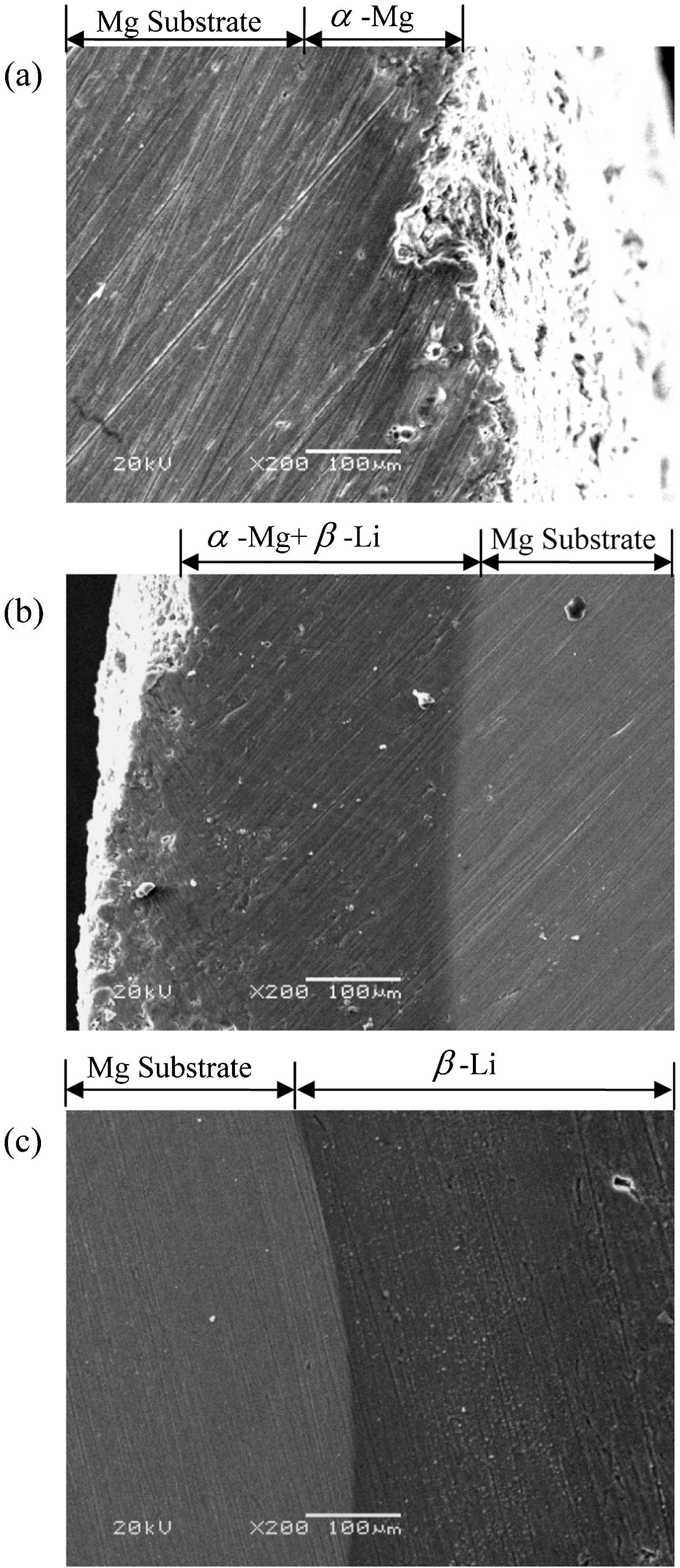
Cross-sectional scanning electron microscopy (SEM) images of Mg–Li alloys formed on Mg electrodes by potentiostatic electrolysis at 753 K for 0·5 h at a −2·26 V; b −2·30 V; c −2·39 V in LiCl–KCl
Electrochemical codeposition of Mg–Li alloys from a molten LiCl–KCl–MgCl2 system
Even though the cathode alloying method showed some advantages in comparison with the one of mixing and melting, such as low metal oxidation, the long process and high energy consumption originating from producing corresponding metallic cathode materials are still problems. Therefore, a simpler method, electrochemical codeposition, was proposed. The method of coelectrodeposition has some advantages, such as reducing electrolysis temperature and energy consumption, short process time, and energy consumption effects. These merits have important use for reference to industrial production of alloys. Electrochemical codeposition has been widely used to prepare binary alloys. Ito et al. 102,103 have investigated the electrochemical codeposition of Sm–Co alloys from LiCl–KCl–SmCl3–CoCl2 melts, and electrochemical formation of Yb–Ni and Sm–Ni alloy films by a Li codeposition method on Ni electrode from corresponding chloride melts. Freyland et al. 104–106 have reported the preparation of NixAl1−x, CoxAl1−x, and ZnSb alloys via codeposition on Au from room temperature molten salt. Tsuda et al. 107,108 have produced a series of Al-based alloys by codeposition from the molten salts of aluminium chloride-1-ethyl-3-methylimidazolium chloride (AlCl3-EtMeImCl). Mg–Li alloys prepared via codeposition were also investigated by Zhang et al. 109–111 Mg–Li alloys were directly prepared by the coelectrodeposition method on an inert electrode in a molten LiCl–KCl (50∶50 wt-%) system at 753 K. However, a dendritic deposit of solid Mg–Li is formed. When the experiment temperature was increased to 943 K (above the melting point of magnesium 923 K), lithium was codeposited on liquid magnesium at more positive potentials causing a lithium–magnesium liquid solution being uniform in shape (better coalescence). The diffusion coefficient of magnesium ions in the melts was determined by cyclic voltammetry, chronopotentiometry and chronoamperometry at 943 K. Three kinds of phases of Mg–Li alloys were prepared via potentiostatic and galvanostatic electrolysis. The codeposition of Mg and Li happens when the current density exceeds about 0·35 A cm−2 (value of limited current density of MgCl2 in LiCl–KCl melts containing 5 wt-% MgCl2). Mg–Li alloys with typical α+β phases could be obtained by potentiostatic electrolysis from LiCl–KCl melts containing 5 wt-% MgCl2 at −2·25 V versus Ag/AgC1 for 2·5 h. The inductively coupled plasma (ICP) analyses of all samples obtained by galvanostatic 109,110 and potentiostatic 111 electrolysis are listed in Tables 3 and 4. Under the same MgCl2 concentration (5 wt-%) in the LiCl–KCl melts, lower current intensities induced less lithium contents of Mg–Li alloys. As the MgCl2 concentrations exceed 10 wt-%, the samples prepared by galvanostatic electrolysis at 6·21 A cm−2 for 2 h are almost pure Mg.
The inductively coupled plasma (ICP) analyses of all samples obtained by galvanostatic electrolysis on Mo electrodes at 6·2 A cm−2 for 2 h from the LiCl–KCl melts containing different concentrations MgCl2
The inductively coupled plasma (ICP) analyses of all samples obtained by potentiostatic electrolysis (versus Ag/AgCl) on Mo electrodes (S = 0·28 cm2) from the LiCl–KCl melts containing different concentrations of MgCl2.
Electrochemical formation of Mg–Li–X alloys by codeposition from their chloride melts
Aluminium, calcium, zinc, manganese, antimony, tin, zirconium and rare earth elements have been widely used as alloying elements in magnesium alloys to improve their strength, corrosion resistance, etc. 112–116 This section presents electrochemical studies on the codeposition of Mg, Li and X (X = Al, Zn, Ca, Mn, Sb and Lns) on a molybdenum electrode in LiCl–KCl–MgCl2–XCln (X = Al, Zn, Ca, Mn, Sb and Lns, n = 2 or 3) melts at 670°C to form Mg–Li–X alloys. The electrochemical reduction process and coelectrodeposition conditions of Mg(ΙΙ), Li (Ι) and a third alloying element were investigated by different electrochemical techniques. The chronopotentiometry and chronoamperometry were first applied to investigate the deposition order of different metals and alloy formation process. Consequently, Mg–Li and Mg–Li based alloys were prepared by a new method of electrolysis in molten salts. This method can start from the origin and incorporate coelectrodeposition, alloying and uniformity. In LiCl–KCl–MgCl2–XCln system, the first formed alloy is Mg–X alloy. The succeeding underpotential deposition of lithium on pre-deposited Mg–X leads to the formation of an Mg–Li–X alloy.
Codeposition of Mg–Li–Al alloys
Mg–Li–Al alloys have become very attractive in recent years because of their low densities and superior mechanical properties. 116 Yan et al. have investigated the codeposition of Mg–Li–Al alloys from LiCl–KCl–MgCl2–AlCl3 melts by employing a series of electrochemical techniques. The Mg–Li–Al alloys with different phases were prepared by potentiostatic and galvanostatic electrolysis. Figure 28 shows chronopotentiograms measured on a molybdenum electrode in LiCl–KCl–MgCl2 (0·525 mol kg−1) melts containing 0·075 mol kg−1 AlCl3 at different current intensities. 117 At a cathodic current lower than −20 mA (current density −0·052 A cm−2), the curves exhibit two potential plateaus (plateaus 1 and 2), which are associated with the reduction of aluminium (plateau 1) and magnesium (plateau 2) ions to metals. When the current reaches −180 mA (−0·47 A cm−2), a third plateau appears caused by the reduction of lithium ions. At this current intensity, codeposition of Mg, Li and Al occurs. It is obvious that the potential ranges for the deposition of Mg, Li and Al are the same as those observed in the cyclic voltammograms (CVs). Ye et al. 118 also attempted to codeposit Mg and Li ions at an Al electrode to form Al–Li–Mg alloys in LiCl–KCl melts containing different concentrations of MgCl2 at 893 K. They prepared Al–Li–Mg alloys by galvanostatic and potentiostatic electrolysis and claimed that the lithium and magnesium contents can be controlled by MgCl2 concentrations by electrolytic parameters.
Chronopotentiograms obtained at different current intensities on a molybdenum electrode (0·3847 cm2) in the LiCl–KCl–MgCl2 (5 wt-%) melts containing 1 wt-% AlCl3 at 670°C
The ICP analyses of all samples obtained by potentiostatic and galvanostatic electrolysis are listed in Tables 5 and 6, respectively. During potentiostatic electrolysis, the more negative the applied potential in the LiCl–KCl–MgCl2 (0·525 mol kg−1) melts with equivalent AlCl3 concentration, the higher the lithium content of Mg–Li–Al alloy. In addition, the aluminium content of Mg–Li–Al alloys increases with increasing AlCl3 concentrations in LiCl–KCl–MgCl2 melts. Under galvanostatic electrolysis, the lower MgCl2 concentration in the LiCl–KCl melts with equivalent AlCl3 concentration at a constant current intensity, the higher the lithium content of the Mg–Li–Al alloys. The aluminium content of Mg–Li–Al alloys increases with an increase in AlCl3 concentrations in LiCl–KCl–MgCl2 melts. These results indicate that the lithium and aluminium contents of Mg–Li–Al alloys are adjustable simply by changing the concentrations of MgCl2 and AlCl3 and the electrolytic parameters.
The inductively coupled plasma (ICP) analyses of all samples obtained by potentiostatic electrolysis on Mo electrodes from the LiCl–KCl–MgCl2 (5 wt-%) melts for 2 h
The inductively coupled plasma (ICP) analyses of all samples obtained by galvanostatic electrolysis (2 A) on Mo electrodes (S = 0·322 cm2) from the LiCl–KCl melts containing different MgCl2 and AlCl3 concentrations for 2 h
Codeposition of Mg–Li–Zn alloys
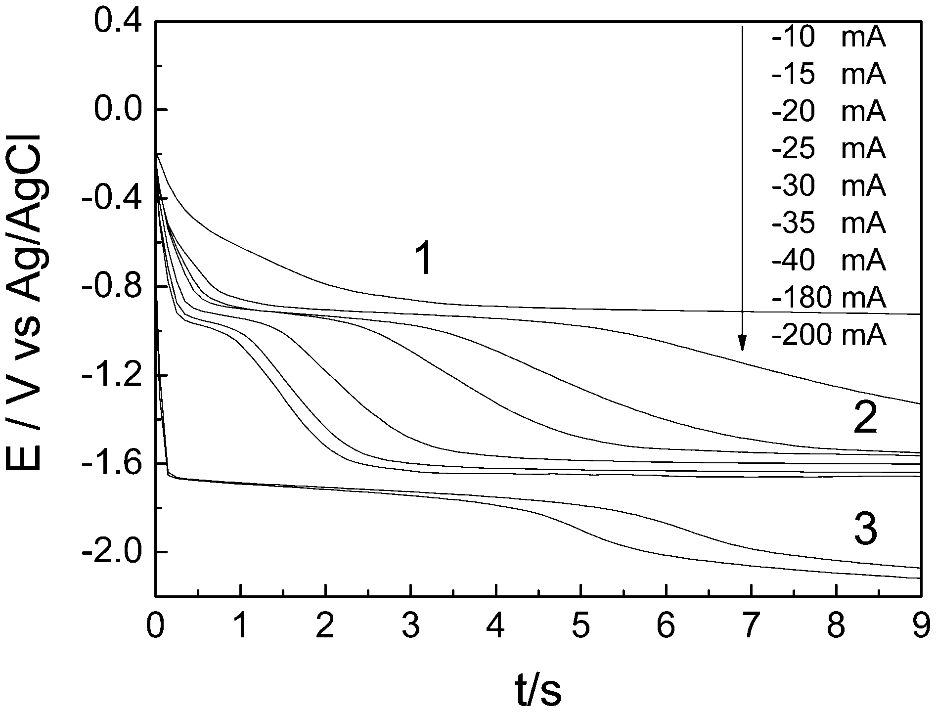
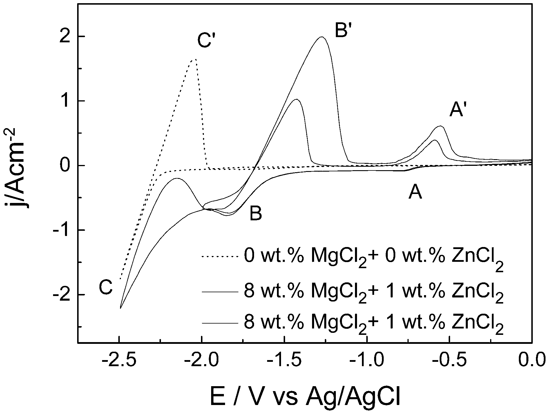
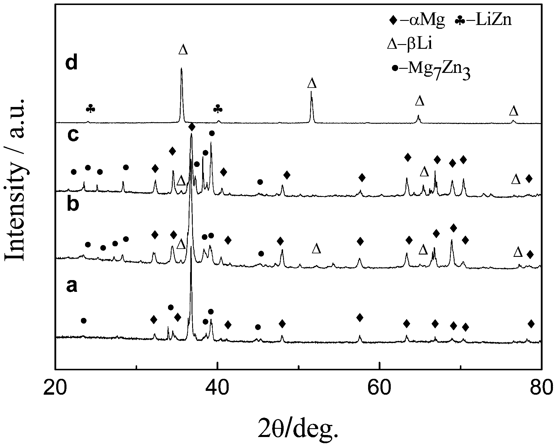
Zn is an important alloying element in Mg base alloys. Yan et al. 119 studied the mechanism of codeposition of Mg–Li–Zn alloys. Figure 29 shows typical CVs obtained at a molybdenum electrode before and after the addition of 8 wt-% MgCl2 and 1 wt-% ZnCl2 in LiCl–KCl melts at 943 K (The dotted curve represents the voltammogram before the addition of MgCl2 and ZnCl2.). Only one couple of cathodic/anodic (C/C′) signals were observed, which corresponds to the deposition and dissolution of liquid Li. The solid curves show the voltammograms measured at different cathodic limits after the addition of MgCl2 and ZnCl2. Peaks A and B in the negative-going scan are ascribed to the formation of a three-dimensional (3D) phase of Zn and Mg, respectively, because the deposition potential of Zn ions is more positive than that of Mg ions in a chloride system. Peaks B′ and A′ in the positive-going scan correspond to the dissolution of Mg and Zn deposit, respectively. Before the addition of MgCl2 and ZnCl2, reduction of Li (I) starts at about −2·25 V on a molybdenum electrode; after the addition of MgCl2 and ZnCl2, the reductions of ions of Zn, Mg, and Li start at approximately −0·70, −1·55, and −2·00 V, respectively. In this way, the potential of Li metal deposition after the addition MgCl2 and ZnCl2 is more positive than the Li metal deposition before the addition. The potential shift is because of a lowering of activity of the deposited metal (Li) in a foreign substrate. The foreign substrate is probably Mg–Zn alloy pre-deposited on the molybdenum electrode. Galvanostatic electrolysis was carried out in LiCl–KCl melts containing MgCl2 and ZnCl2 with different concentrations on molybdenum electrodes at 943 K. Figure 30 shows the complicated XRD patterns of Mg–Li–Zn alloy samples obtained by galvanostatic electrolysis from the LiCl–KCl melts containing 5–10 wt-% MgCl2 and 1–3 wt-% ZnCl2 at 6·21 A cm−2 for 2 h. As seen from the XRD patterns, the Mg–Li–Zn alloys are composed of α+Mg7Zn3, (α+β)+Mg7Zn3, and β+LiZn phases. In patterns a–c, all Mg–Li–Zn alloys contain the Mg7Zn3 phase, which proves that the first formed Mg–Zn alloy is Mg7Zn3. However, a new LiZn phase occurs in pattern d when the concentration of MgCl2 is 5 wt-% in LiCl–KCl–ZnCl2 (1 wt-%) melts. Moreover, the lithium content of Mg–Li–Zn alloys increases (from α, α+β to β phase) with a decrease of MgCl2 concentrations in the LiCl–KCl–ZnCl2 (1 wt-%) melts at constant current intensity.
Typical cyclic voltammograms (CVs) of the LiCl–KCl melts before (dotted line) and after (solid line) the addition of 8 wt-% MgCl2 and 1 wt-% ZnCl2 on molybdenum electrodes at 670°C
X-ray diffraction (XRD) patterns of deposits obtained by galvanostatic electrolysis on Mo electrodes (S = 0·322 cm2) in the LiCl–KCl melts with a 10 wt-% MgCl2 and 1 wt-% ZnCl2; b 9 wt-% MgCl2 and 1 wt-% ZnCl2; c 9 wt-% MgCl2 and 3 wt-% ZnCl2; d 5 wt-% MgCl2 and 1 wt-% ZnCl2 at 2 A for 2 h
Codeposition of Mg–Li–Ca alloys
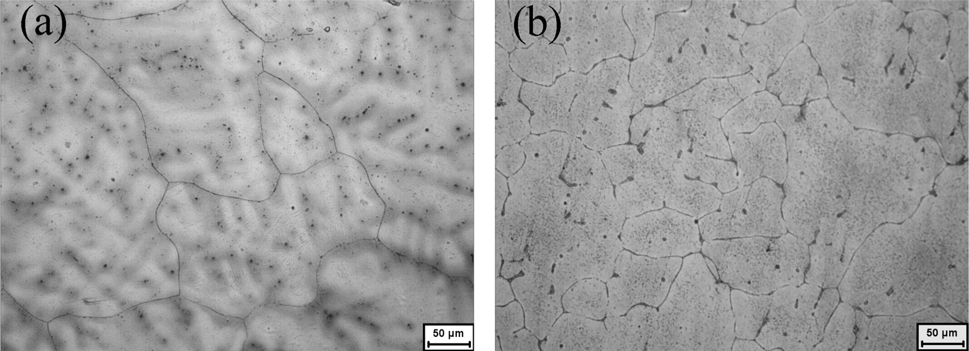
The addition of low-cost Ca into magnesium-based alloys can raise the oxidising combustion temperature of magnesium-based alloy, refine the microstructure, and improve the mechanical properties at room temperature and heat resistance at elevated temperature. 120 Yan et al. have successfully prepared Mg–Li–Ca alloys by codeposition of Mg, Li and Ca from LiCl–KCl–MgCl2–CaCl2 melts. 121 According to Faraday’s law, the mass of the deposited substance is related to I and t. If the authors want to obtain a larger mass Mg–Li–Ca alloy in a relatively short time, they have to perform the electrolysis at a more negative potential or current density. Under potentiostatic electrolysis, however, the current often exceeded the current limit of the electrochemical workstation (−2–2 A, −4–4 V) with the growth of the electrode surface (growth of the nucleation of the M g–Li–Ca alloy on a Mo electrode). Therefore, the experiment cannot be continuously completed because of an interruption in the measurement. Certainly, this problem can be overcome when an updated instrument with a wider current range is employed. This is because there was a limit to the increase of the electrode surface. The nucleation of Mg–Li–Ca alloy on Mo electrode grew to some extent and then the liquid Mg–Li–Ca alloy departed from the Mo electrode because of the effect of surface tension. Under galvanostatic electrolysis, this problem did not occur because of a wide potential range of the electrochemical workstation. Therefore, galvanostatic electrolysis was carried out using a much higher current density than the onset one for codeposition of Mg, Li and Ca in LiCl–KCl–CaCl2–MgCl2. The microstructures of the Mg–Li–Ca alloys by codeposition from LiCl–KCl–CaCl2 (1 wt-%) melts containing 9 and 8 wt-% MgCl2 exhibit typical α and β phases, respectively, as given in Fig. 31a and b . The average grain sizes of the α and β Mg–Li–Ca alloys are about 100 and 70 μm, respectively. In order to determine the distribution of the elements Mg and Ca in the Mg–Li–Ca alloy, mapping analysis of the elements was employed. Figure 32 shows a scanning electron microscopy (SEM) and EDS mapping analyses of the Mg–Li–Ca alloy by codeposition from LiCl–KCl–CaCl2 (1 wt-%) melts containing 8 wt-% MgCl2. The element Mg distributes homogeneously throughout the Mg–Li–Ca alloy. However, Ca distribution is not uniform and mainly disperses along the grain boundaries.
Optical micrographs of the Mg–Li–Ca alloys by codeposition from LiCl–KCl–CaCl2 (1 wt-%) melts containing a 9 wt-% and b 8 wt-%MgCl2

Scanning electron microscopy (SEM) and EDS mapping analyses of the Mg–Li–Ca alloy by codeposition from LiCl–KCl–CaCl2 (1 wt-%) melts containing 8 wt-% MgCl2
Codeposition of Mg–Li–Mn alloys 122
Galvanostatic electrolysis was carried out in LiCl–KCl melts containing MgCl2 and MnCl2 with different concentrations on molybdenum electrodes at 893 K. Figure 33 shows the XRD patterns of Mg–Li–Mn alloy samples obtained by galvanostatic electrolysis from the LiCl–KCl melts containing 6–11 wt-% MgCl2 and 2 wt-% MnCl2 at 7·14 A cm−2 for 2 h. The observed peaks were identified as α-Mg, β-Li, and Mn phase. As seen from the XRD patterns, the Mg–Li–Mn alloys are composed of α-Mn, (α+β)+Mn, and β+ Mn phases. In patterns a–c, all Mg–Li–Mn alloys contain the Mn phase, which proves that intermetallic compound was not formed in Mg–Li–Mn alloys at this temperature. According to the phase diagram of the Mg–Mn and Li–Mn system, the concentration of Mn will be small in Mg–Li alloys since the solubility of Mn in Mg is around 0·8 at-% and Mn is insoluble in Li metal at 893 K. Moreover, the lithium content of Mg–Li–Mn alloys increases (from α, α+β to β phase) with a decrease in MgCl2 concentrations in the LiCl–KCl–MnCl2 (2 wt-%) melts at constant current intensity. Therefore, under the condition of electrolysis, the lithium content and phase composition of Mg–Li–Mn alloys are adjustable simply by changing concentrations of MgCl2 and the electrolytic parameters.
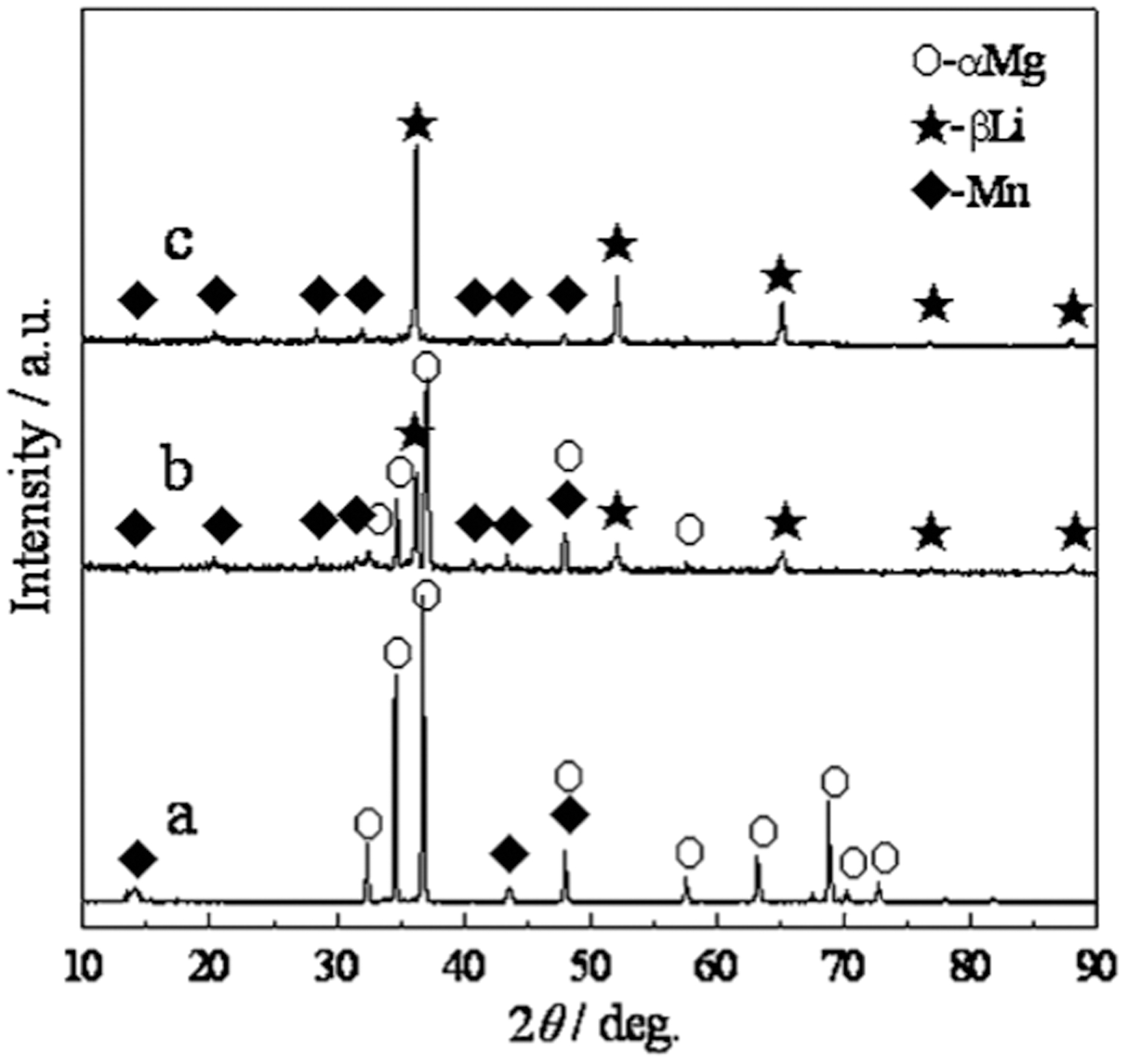
X-ray diffraction (XRD) patterns of deposits obtained by galvanostatic electrolysis on Mo electrodes (S = 0·28 cm2) in the LiCl–KCl melts with a 11 wt-% MgCl2 and 2 wt-% MnCl2; b 8 wt-% MgCl2 and 2 wt-% MnCl2; c 6 wt-% MgCl2 and 2 wt-% MnCl2 at 2·00 A for 2 h at 893 K
Codeposition of Mg–Li–Sb alloys
Sb is one of alloying elements of Mg alloys. Adding a small amount of Sb could improve mechanical properties, thermal stability and grain refinement in comparison with the base alloy. 123 Wei et al. 124 investigated the preparation of Mg–Li–Sb alloys by galvanostatic electrolysis in LiCl–KCl melts containing MgCl2 and SbCl3 with different concentrations on a molybdenum electrode at 673 K for 2 h. Owing to the low electrolysis temperature, after the process of electrolysis, the temperature of the salts was increased to 973 K after holding for 0·5 h. Li content of Mg–Li–Sb alloys increases with a decrease in MgCl2 concentration in LiCl–KCl melts. The higher the SbCl3 concentration in LiCl–KCl melts, the higher the Sb content of Mg–Li–Sb alloy can be obtained. According to these results, Sb and Li contents of Mg–Li–Sb alloys can be adjusted by changing MgCl2 and SbCl3 concentrations in LiCl–KCl melts. Figure 34 shows the XRD patterns of alloys listed in Table 7. With an increase of Li and Sb content, the amount of Li3Sb increased. When Li content is 12·90 wt-% and Sb content is 2·70 wt-%, Mg3Sb2 phases appear in the alloy.
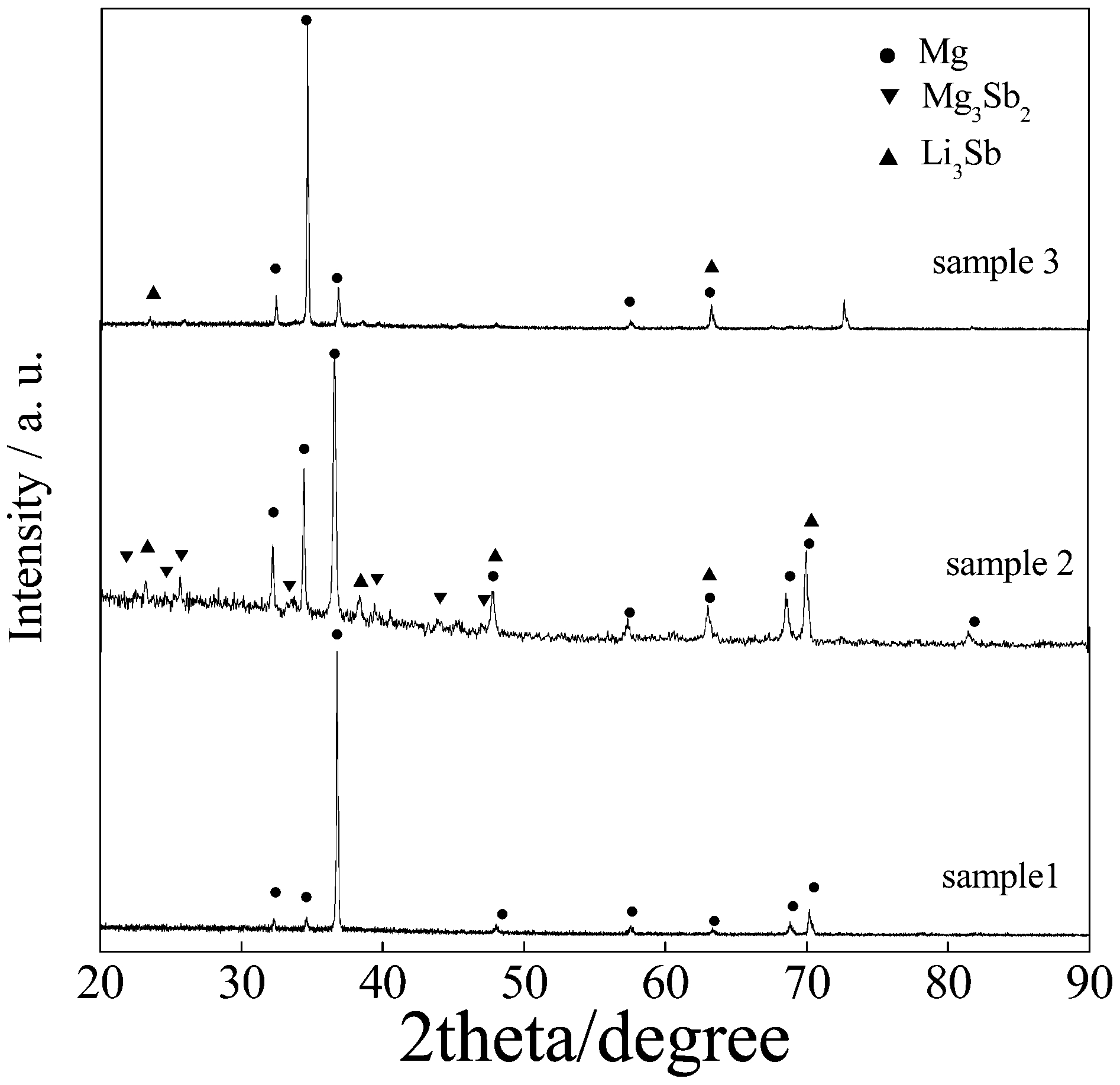
X-ray diffraction (XRD) patterns of deposits obtained by galvanostatic electrolysis on a Mo electrode (S = 0·322 cm2) in the LiCl–KCl melts containing different concentrations of MgCl2 and SbCl3 at 673 K for 2 h, and then enhanced melts temperature to 973 K holding 0·5 h
The inductively coupled plasma (ICP) analysis of all samples obtained by galvanostatic electrolysis (12·4 A cm−2) on Mo electrodes (S = 0·322 cm2) from the LiCl–KCl–MgCl2–SbCl3 melts at 673 K for 2 h, and then enhanced melts temperature to 973 K holding 0·5 h
Codeposition of Mg–Li–REs (rare earths) alloys
Most commercial Mg–Li–RE alloys are prepared by directly mixing and melting pure magnesium, lithium and rare earth metals. This conventional method results in high energy consumption for industrial production of pure magnesium, lithium and rare earth metals. Specifically, pure RE metals are extremely expensive because it is too difficult to extract and purify them. In recent years, electrochemical codeposition has been used to prepare RE alloys. A series of Mg–Li–RE alloys have been successfully prepared.
Variable valence REs (Sm, Eu and Yb) cannot be directly electrolysed from LiCl–KCl melts since the reduction potential of RE(II) to RE(0) is even more negative than that of Li(I) to Li(0). It is well known that the depolarisation effect of REs with Mg is larger than that of Li. Therefore, codeposition of REs and Mg ions is an effective way to obtain REs by electrolysis. Ye et al. 125,126 have investigated electrodeposition of Mg–Yb alloy film and Mg–Li–Yb alloys at solid magnesium cathode in the molten LiCl–KCl–YbCl3 system at 773 K.
Figure 35 shows typical CVs obtained at a Mo electrode (curve 1) and an Mg electrode (curves 2 and 3) before and after the addition of 2 wt-% YbCl3 in LiCl–KCl melts at 743 K. The dotted curve 1 represents the voltammogram before the addition of YbCl3 at a Mo electrode. A sharp increase in cathodic current from approximately −2·33 V (versus Ag/AgCl) was observed. The cathodic signal B can be ascribed to the deposition of Li. The dash curve 2 shows the voltammogram before the addition of YbCl3 at an Mg electrode. A cathodic current was seen from about −2·12 V. Since this potential value is more positive than that of Li metal deposition, the cathodic current is thought to be caused by the formation of Mg–Li alloys. The potential shift is because of a lowering of activity of the deposited metal (Li) in the Mg phase. After adding 2 wt-% YbCl3, peak A 1 associated with the reduction of Yb(III) to Yb(II) ions was first detected at about −0·77 V in solid curve 3. Afterwards, a cathodic current was observed. The cathodic current A 2 probably corresponds to the formation of Mg–Yb alloys. Finally, the cathodic signal B observed in the cathodic limit can be ascribed to the formation of Mg–Li–Yb alloys. In the anodic direction, peaks B′ and A 2′ correspond to the dissolution of Li (0) and Yb (0) from the Mg–Li–Yb alloys, respectively. Afterwards, anodic peak A 1′ can be ascribed to the oxidation of Yb(II) to Yb(III) ions. Potentiostatic electrolysis experiments were conducted in the LiCl–KCl–YbCl3 (2 wt-%) melts for 3 h using Mg electrodes as a working electrode at −1·80 V (sample 1) and −2·40 V (sample 2). Figure 36 shows the XRD patterns of samples 1 and 2. The diffraction peaks for sample 1 could be assigned to α-Mg phase, indicating the Yb and Li contents in Mg–Li–Yb alloys were relatively low. However, typical α+β phase Mg–Li–Yb alloys were formed when the applied potential is at −2·40 V. The observed peaks for sample 2 are identified as (α+β)+Mg2Yb phases.
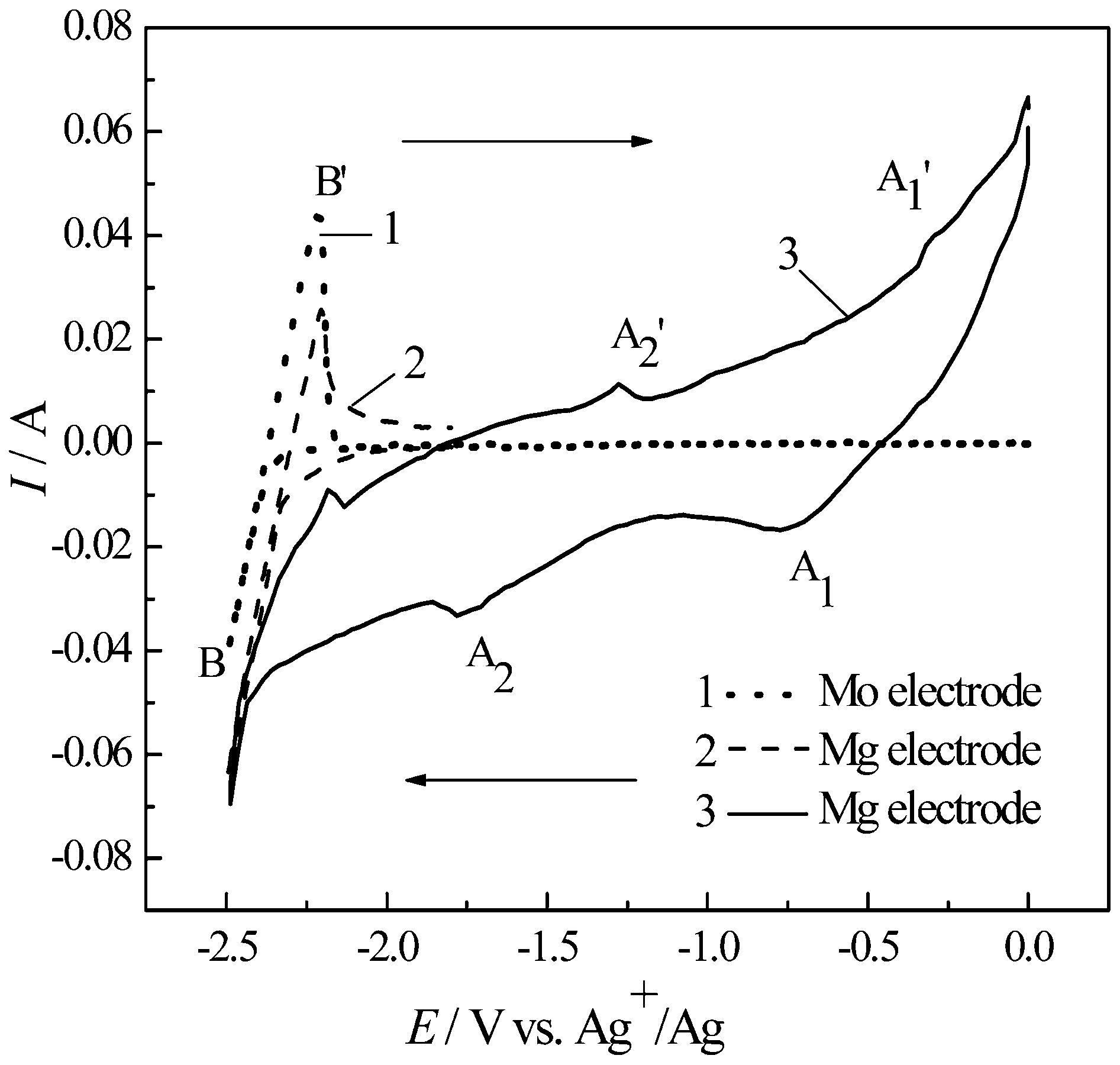
Cyclic voltammograms (CVs) of LiCl–KCl melts before and after the addition of 2 wt-% YbCl3 at a Mo electrode (S = 0·104 cm2; curve 1) and an Mg electrode (S = 0·457 cm2; curves 2 and 3) at 743 K. Scan rate: 0·1 V s−1
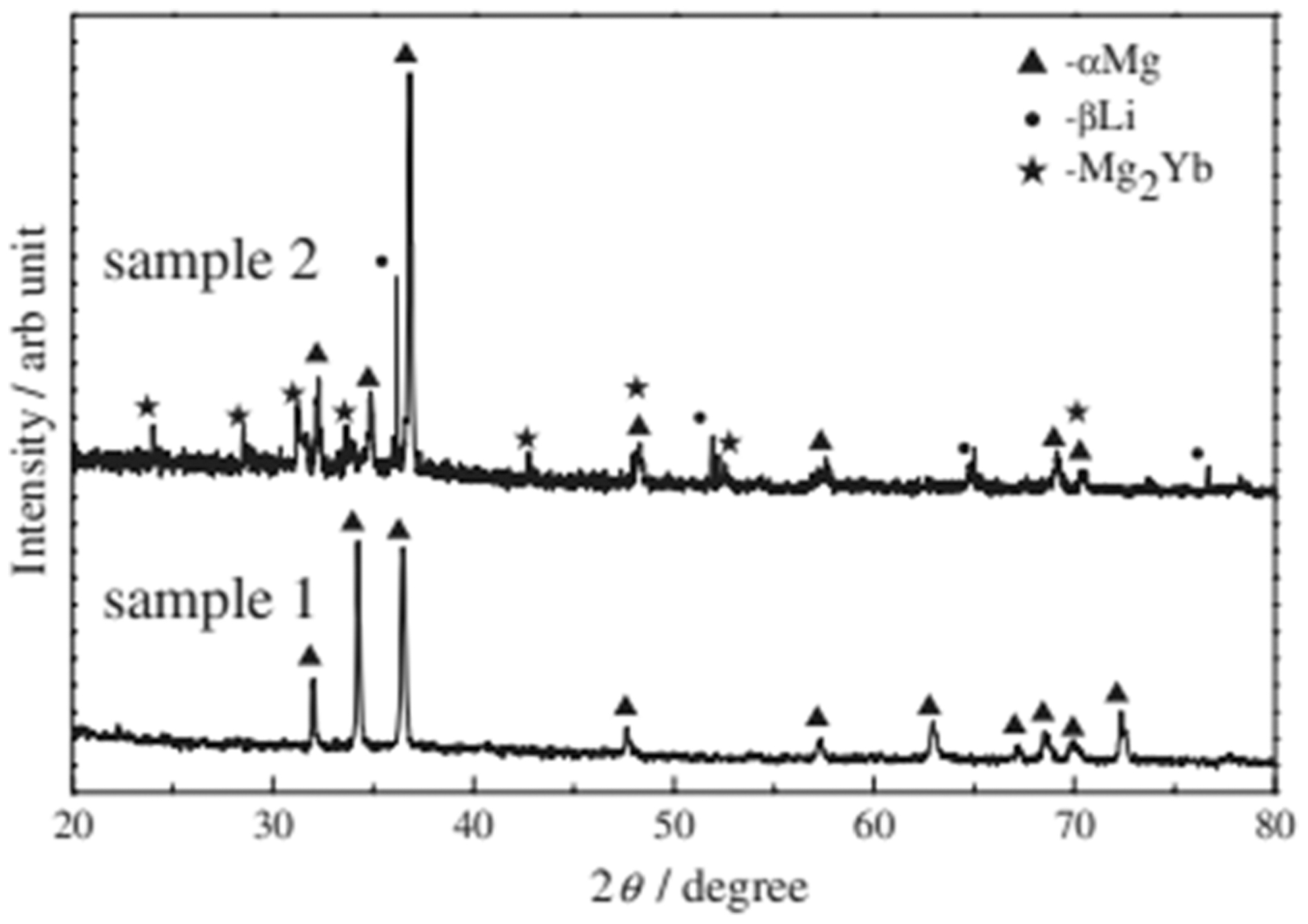
X-ray diffraction (XRD) patterns of samples 1 and 2 (followed by a post-thermal treatment at 973 K) at −1·80 and −2·40 V (versus Ag+/Ag) obtained at Mg electrodes (S = 0·457 cm2) in the LiCl–KCl–YbCl3 (2 wt-%) melts by potentiostatic electrolysis for 3 h at 743 K, respectively
Zhang et al. 127–129 have investigated the preparation of Mg–Li–RE (La, Gd and Yb) alloys from RE2O3 in the LiCl–KCl(–KF)–MgCl2 melts. Galvanostatic electrolysis was carried out in a molten KCl–LiCl–MgCl2–RE2O3–KF system on molybdenum electrodes at 923–973 K. In the beginning stage of electrolysis, compared with the higher concentration of LiCl in the melts, MgCl2 reached limited diffusion current density and deposited first. The temperature of 923–973 K was higher than the melting point of metal magnesium (923 K). So, the liquid magnesium cathode was around the molybdenum wire. And then Li+ and RE3+ began to deposit on the surface of the pre-coated liquid magnesium cathode.
From Table 8, the lower the MgCl2 concentration in the LiCl–KCl–KF melts, with equivalent La2O3 concentration at a constant current intensity, the higher the lithium content of the Mg–Li–La alloys. In the case of neglecting La deposition (the concentration of La2O3 in the melts is very low), the molar ratio of deposited Mg and Li is proportional to the ratio of their current densities. The limited diffusion current density of MgCl2 is proportional to its concentration in the melts. Therefore, Mg content in the alloy decreases with decreasing MgCl2 concentration in the melts. The authors can also find that the lanthanum content of Mg–Li–La alloys increase with increasing the La2O3 concentrations in KCl–LiCl–MgCl2–La2O3–KF melts.
The inductively coupled plasma (ICP) analyses of samples obtained by galvanostatic electrolysis on Mo electrodes (S = 0·322 cm2) from KCl–LiCl–MgCl2–La2O3–KF melts at 943 K
In order to examine the uniformity of the elements Mg and Yb distributed in Mg–Li–Yb alloys, elemental mapping analysis was employed. Figure 37 shows SEM morphology (Fig. 37a ) and EPMA area analysis (Fig. 37b and c ) of Mg–Li–Yb alloys prepared by galvanostatic electrolysis with 3 A, 60 min at 660°C in the melts (LiCl∶KCl∶KF∶MgCl2 Yb2O3 = 40∶40∶10∶9·5∶0·5, wt-%) on Mo electrodes. The grey zone in the SEM corresponds to α-Mg phase. Figure 37b shows that the element Mg distributes homogeneously in the Mg–Li–Yb alloys. The distribution of Yb is not uniform in the alloy and is mainly distributed in the grain boundaries of α-Mg, as presented in Fig. 37c .
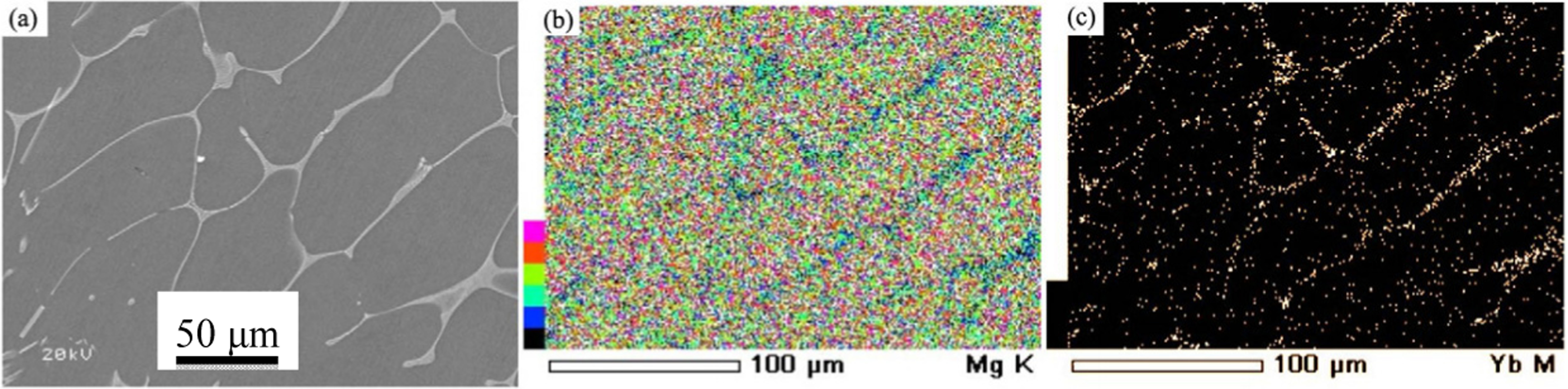
Scanning electron microscopy (SEM) and EPMA mapping analysis of the Mg–11·8Li–8·4Yb alloy obtained by galvanostatic electrolysis with 3 A, 60 min at 660°C in the melts (LiCl∶KCl∶KF∶MgCl2∶Yb2O3 = 40∶40∶10∶9·5∶0·5, wt-%) on Mo electrodes a SEM; b and c Area analysis of Mg and Yb in Mg–Li–Yb alloy
Zhang et al. 130–133 have also prepared Mg–Li–RE (Y, Sm and Er) alloys from RECl3/K3RECl6 in the LiCl–KCl–MgCl2 melts. Figure 38 shows the CVs of the LiCl–KCl melts before and after the addition of MgCl2 and SmCl3 on molybdenum electrodes at 903 K. The dotted line corresponds to a CV of the LiCl–KCl melts in the absence of MgCl2 and SmCl3. A sharp increase in cathodic current from –2·40 V is observed. The cathodic signal C can be ascribed to the deposition of Li because no alloys or intermetallic compounds exist for the Mo–Li binary system at 903 K. In the reverse scan, an anodic peak C′ corresponding to the dissolution of Li is observed. The solid curves show the voltammograms measured after the addition of MgCl2 and SmCl3. Two cathodic/anodic current peaks observed at approximately –0·90 and –0·75 V are attributed to the reduction of Sm(III) and the oxidation of Sm(II), respectively. In the negative-going scan, peak B is observed from approximately –1·80 V, which corresponds to the reduction of Mg(II). The deposition of Li(I) is observed at a more positive potential after the addition MgCl2 and SmCl3 than that before the addition. The potential shift is caused by the formation of Mg–Li alloys. The redox couple Sm(II)/Sm(0) is not observed in this experiment because the reduction of Sm(II) is at a high negative value close to that of the lithium reduction. It is probably hidden by a larger scaled cathodic current of Li deposition.
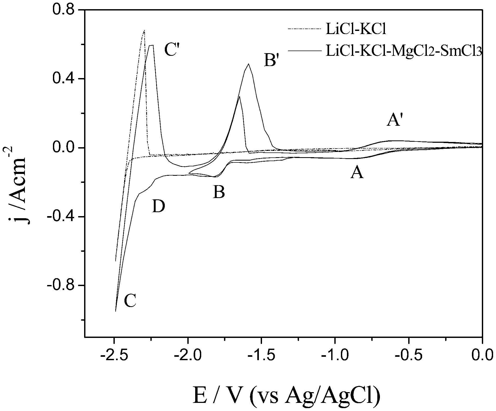
The cyclic voltammograms (CVs) of the LiCl–KCl melts before (dotted line) and after (solid line) the addition of MgCl2 and SmCl3 (CMg(II) = 1·73×10−4 mol cm−3, CSm(III) = 1·359×10−4 mol cm−3) on molybdenum electrodes at 903 K (903 K). Scan rate: 0·1 V s−1
From Table 9, under galvanostatic electrolysis, the samarium content of Mg–Li–Sm alloys increases with increasing SmCl3 concentrations in LiCl–KCl–MgCl2 melts. With equivalent SmCl3 concentration at constant current intensity, the longer the electrolytic time, the higher the lithium content in Mg–Li–Sm alloys. Based on these results, it can be concluded that the lithium and samarium contents in Mg–Li–Sm alloys can be adjusted by changing the electrolytic time and concentration of SmCl3.
The inductively coupled plasma (ICP) analyses of samples obtained by electrolysis at 4 A on Mo electrodes (S = 0·322 cm2) from LiCl–KCl–MgCl2 melts containing different SmCl3 concentrations
Codeposition of Mg–Li base quarternary alloys
The fabrication of quarternary alloys by direct codeposition in molten salts has seldom been reported in the literature. Zhang et al. 134–137 have reported a new approach to synthesise quarternary Mg–Li–Ce–La, Mg–Li–Zn–Mn, Mg–Li–Al–Zn, and Mg–Li–Al–La alloys directly in the LiCl–KCl–MgCl2 melts with the addition of other corresponding raw materials using a coelectrodeposition method. The authors take Mg–Li–Ce–La, Mg–Li–Zn–Mn, and Mg–Li–Al–Zn alloy as examples.
In Fig. 39, the dotted line represents the CV of LiCl–KCl–RE2(CO3)3 (3·8 wt-%). There are no other cathodic/anodic signals except the deposition/oxidation of liquid lithium. The solid line represents the CV after the addition of 1 wt-% MgCl2. This voltammogram exhibits another three reduction waves on the forward scan with the peak potential of −1·70 V (peak A), −1·96 V (peak B), and −2·07 V (peak C). Peak A corresponds to the deposition of Mg. Cerium and lanthanum were reduced via the one-step process corresponding to the peaks B and C, respectively. The cathodic signals of Ce and La were detected after the addition of MgCl2, which proves that some reactions occur between RE2(CO3)3 and MgCl2. But the oxidation peaks of Ce and La were not detected significantly, because the peak D′ was too high, and the peaks hid the oxidation peaks of Ce and La. To identify the phases of alloys, XRD was used to analyse the alloy samples. X-ray diffraction patterns (Fig. 40) indicate that the main phases of the alloys are α-Mg, CeMg12, and La2Mg17 when the content of Li is low. When the content of Li is high, the main phases are β-Li, CeMg3, and LaMg3. The ternary phase diagrams of RE(La, Ce)–Mg–Li confirm this conclusion.
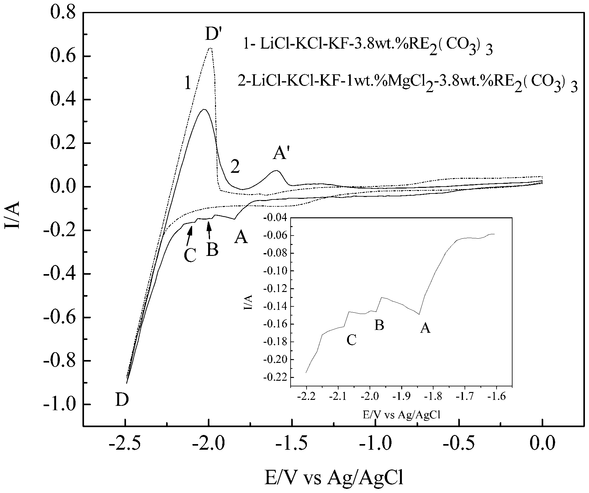
Cyclic voltammograms (CVs) of (dotted line) LiCl–KCl–3·8 wt pct RE2(CO3)3 melts and (solid line) LiCl–KCl–1·0 wt pct MgCl2–3·8 wt pct RE2(CO3)3 system at 0·1 V s−1 and T = 1023 K. Working electrode: Mo (S = 0·314 cm2); counter electrode: graphite; reference electrode: Ag/AgCl
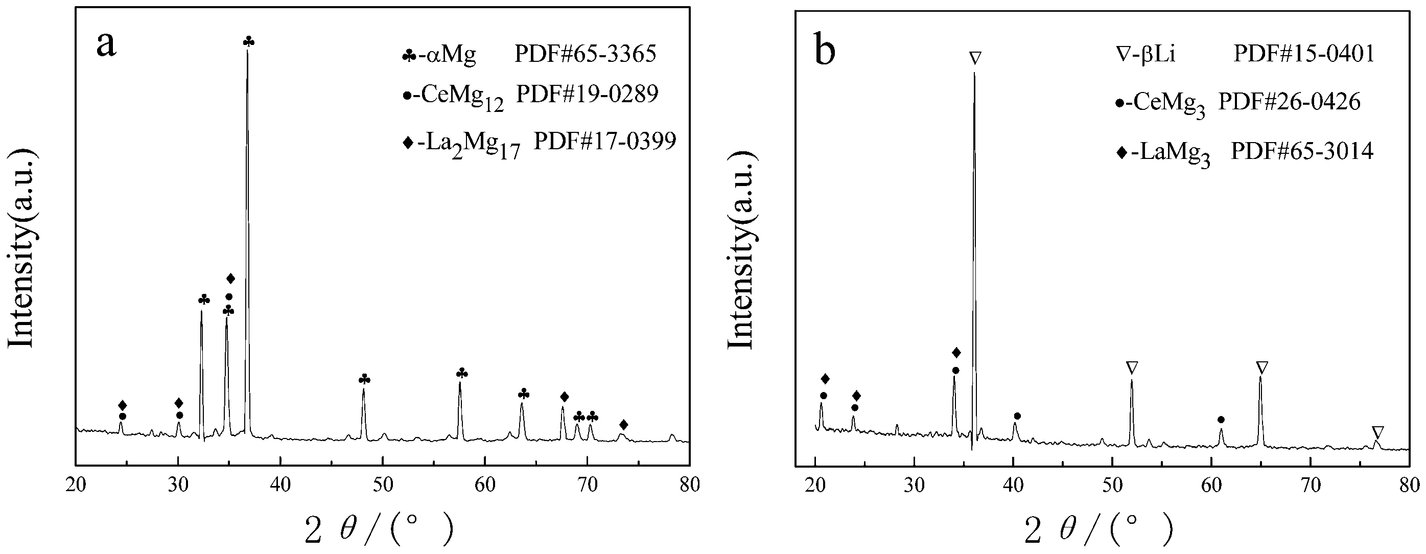
X-ray diffraction (XRD) patterns of different alloy samples obtained by galvanostatic electrolysis with a 15·9 A cm−2 and b 18·5 A cm−2 in the LiCl–KCl–MgCl2(13·6 wt pct)–RE2(CO3)3(0·5 wt pct)-KF(4·5 wt pct) melts on Mo electrodes at 1023 K for 2 h
Figure 41 shows representative CVs measured in the LiCl–KCl melts at a molybdenum electrode containing different concentrations of MgCl2, ZnCl2, and MnCl2 at 943 K. From curves a and b in Fig. 41, excluding the pair of peaks corresponding to reduction/oxidation of liquid lithium (peaks D/D′), the cathodic peak A/B is ascribed to a three-dimensional (3D) phase formation of Zn/Mn electrode-position, respectively. Peak A′/B′ in the positive-moving scan corresponds to the dissolution of deposited Zn/Mn, respectively. With the addition of MgCl2, a sharp peak C that corresponds to the reduction of Mg2+ was observed. Peak C′ in the positive-moving scan corresponds to the dissolution of deposits because the deposition potential of Mg2+ is more positive than that of Li+ ions in a chloride system.
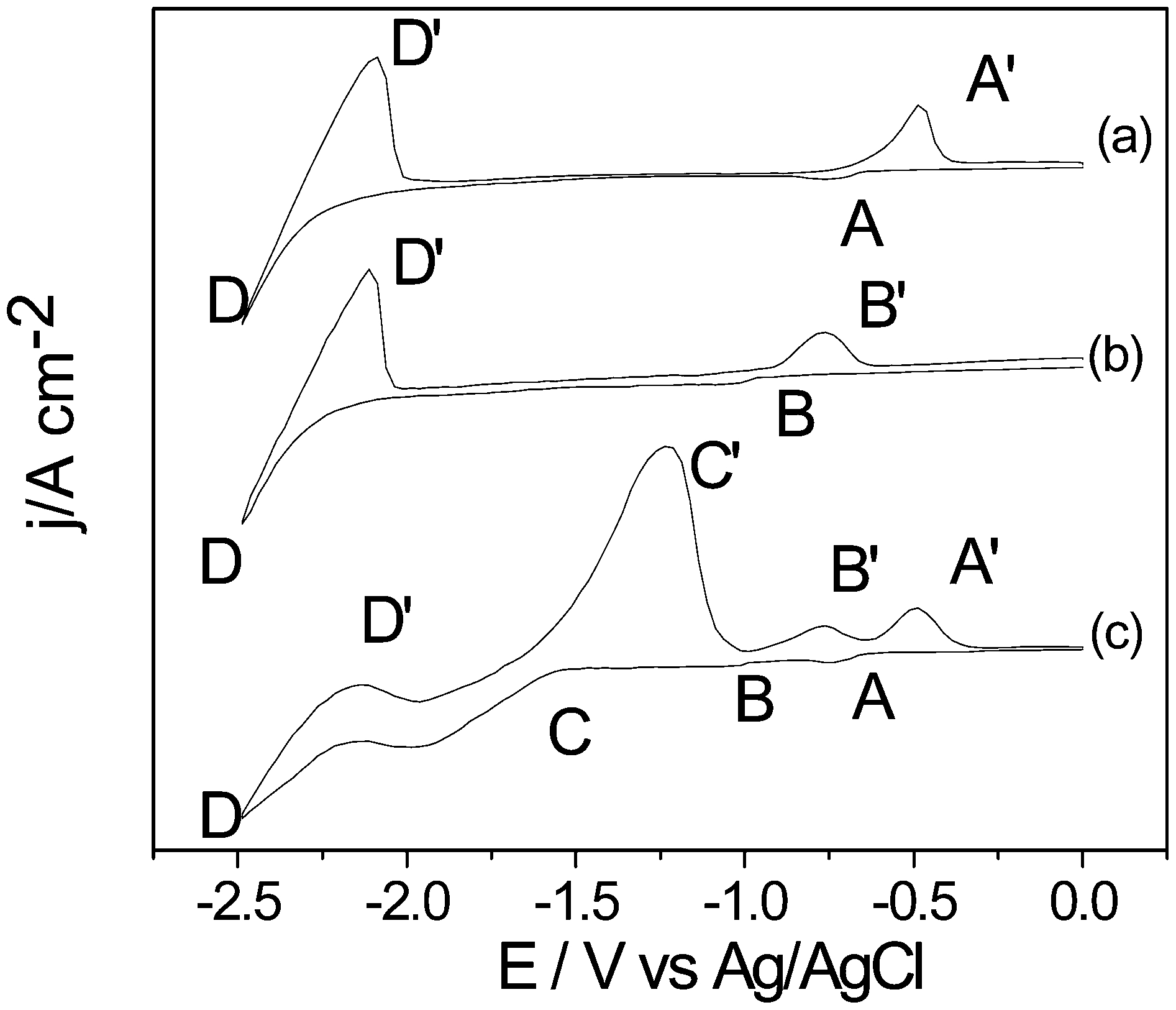
Cyclic voltammograms (CVs) of the LiCl–KCl melts containing different concentrations of MgCl2, ZnCl2, and MnCl2 on molybdenum electrodes at 943 K. Scan rate: 0·05 V s−1: a containing 2·0 wt pct ZnCl2; b containing 1·0 wt pct MnCl2; and c containing 2·0 wt pct ZnCl2, 1·0 wt pct MnCl2, and 8·0 wt pct MgCl2
The electrodeposition process of Mg–Li–Al–Zn alloys is similar to those of Mg–Li–Ce–La and Mg–Li–Zn–Mn alloys. The distribution of elements in quarternary alloys is another emphasis in our investigation. To examine the distribution of the elements of Mg, Al, and Zn in the Mg–Li–Al–Zn alloy, elemental mapping analysis was employed. Figure 42 shows a SEM and EDS mapping analyses of the Mg–Li–Al–Zn alloy by codeposition from LiCl–KCl–AlCl3(1 wt-%)–ZnCl2(1 wt-%) melts containing 8 wt-% MgCl2. The element Mg distributes mainly in the matrix, and element Al distributes homogeneously throughout the Mg–Li–Al–Zn alloy. However, Zn distribution is not uniform and is mainly located at grain boundaries. Scanning electron microscopy equipped with EDS quantitative analysis was employed to further investigate the distribution of the element of Al and Zn. At the same time, the results of EDS demonstrate that the grain boundary dissolves more Zn (14·77 mass-% at point 001) than the grain does (2·67 mass-% at point 002).
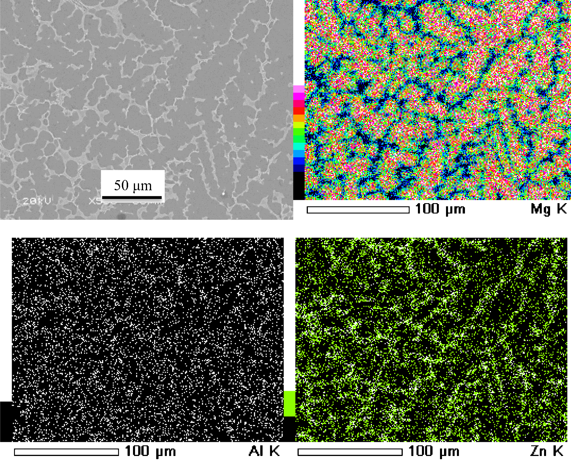
Scanning electron microscopy (SEM) and EDS mapping analyses of the Mg–Li–Al–Zn alloy by codeposition from LiCl–KCl–AlCl3(1 wt-%)–ZnCl2(1 wt-%) melts containing 8 wt-% MgCl2
Mg–Li based alloys with different lithium and X (X = Al, Zn, Ca, Mn, Sb and Lns) contents were obtained via potentiostatic and galvanostatic electrolysis. The alloys obtained were characterised by XRD, optical microscopy, SEM, energy dispersive spectrometry and ICP. Lithium and X contents of Mg–Li–X alloys can be controlled by MgCl2 and XCln concentrations and the electrolytic parameters. These results provide a reliable theoretical basis for the preparation of alloys by electrolysis in industry.
Surface technology of Mg–Li alloys
Mg–Li alloys are highly sensitive to atmospheric corrosion because of the inclusion of lithium. Loose oxide film can be formed on Mg–Li alloy surfaces in ambient atmosphere. The oxide film includes four layers: the top layer is a mixture of Li2O and Mg(OH)2; the second layer is a mixture of Li2O, Mg(OH)2 and MgO; the third layer is a mixture of LiOH, MgO, Mg(OH)2, Li2O and Mg; and the bottom layer was the mixture of Li2O, MgO, Mg and Li. Because of the loose oxide film on Mg–Li alloys surface, lithium oxides enriched at the outer oxide layer. 138 As a result, the protection performance of the surface oxide film is limited. The Mg–Li alloys react severely, even at room temperature, when exposed to the atmosphere or aqueous solutions, especially under marine atmosphere conditions. 139 Under the sea water conditions, uniform corrosion of the Mg–Li alloys are very strong. In the process of the corrosion, large quantities of lithium are dissolved; soon the magnesium that is left is under the loose oxide film. It is the poor corrosion resistance that limits the extensive utilisation of Mg–Li alloys. One of the most effective ways to prevent corrosion is to coat the base material. Coatings can protect a substrate by providing a barrier between the metal and its environment and/or through the presence of corrosion inhibiting chemicals in them.
Recently, a large number of surface-treatment techniques have been developed to improve their corrosion resistance of traditional magnesium alloys, such as chemical conversion technology, anodising, electroless plating, vapour-phase deposition, MAO, and organic coatings. 140–148 Each of these techniques has their own advantages and disadvantages. The purpose of this section is to provide a clear picture of the surface technologies currently available.
Electroless plating
It is often desirable to alter the surface properties of Mg–Li alloys in order to improve their corrosion and wear resistance, solderability, electrical conductivity and decorative appearance. This can be accomplished by coating the part with a metal that has the properties necessary for the specific application. One of the most effective and simple techniques for introducing a metallic coating to a substrate is electroless plating. In this case, a metal salt in solution is reduced to its metallic form on the surface of the workpiece. In electroless or chemical plating, the reducing electrons are supplied by a chemical reducing agent in solution or, in the case of immersion plating, the substrate itself.
Before electroless plating, the pre-treated Mg–Li alloy sheets were pre-plated in a NiCO3·2Ni(OH)2·4H2O solution to form a thin Ni–P alloy film and then plating in a NiSO4·6H2O solution. The results showed that a compact, uniform and typical spherical nodular structure plating layer (Fig. 43) was obtained, which was integrated into the matrix metal. The P content of the Ni–P coating reached 13·56% (wt-%). The hardness value of the Ni–P coating was about Vickers hardness (HV) 549. The polarisation curve showed that the corrosion potential of the Ni–P coating has an excellent anti-corrosion property. 149
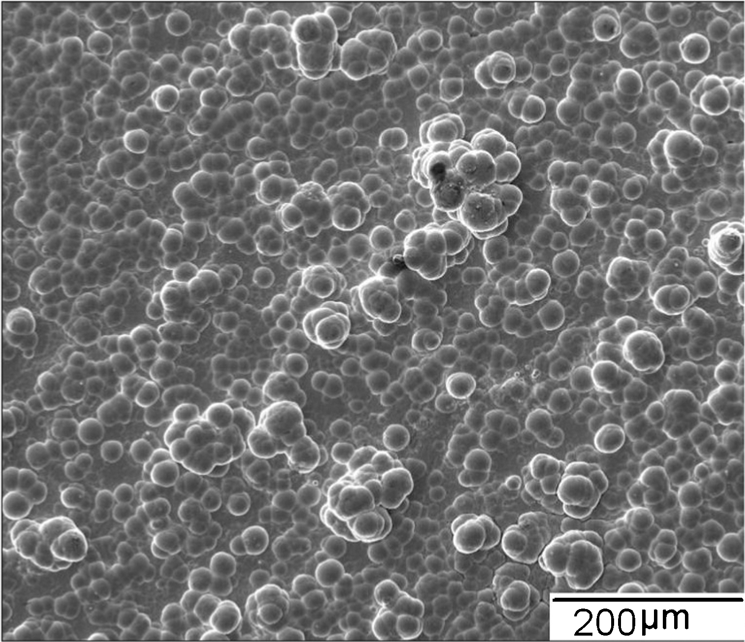
Surface morphology of Ni–P coating on Mg–Li alloy
Conversion coatings
Conversion coatings are produced by chemical or electrochemical treatment of a metal surface to produce a superficial layer of substrate metal oxides, phosphates, chromates, or other compounds that are chemically bonded to the surface. 150,151 Among these kinds of surface protection methods, chemical conversion treatment is paid more attention because the conversion coatings are comparatively cheap, easily operated and hence are widely used. The chemical conversion coatings on Mg–Li alloys are used to provide good paint-base properties and corrosion protection to the metal. 152 Chemical conversion coatings protect the Mg–Li alloys from corrosion by acting as an insulating barrier between the substrate and the environment and/or by containing corrosion inhibiting compounds.
There are many different types of conversion coatings to Mg–Li alloys, including chromate, stannate, phytic acid, fluorozirconate, rare earth treatments, phosphate/phosphate–permanganate, molybdate/permanganate, etc. As with all surface treatments, cleaning and pre-treatment of the sample is crucial to obtaining a high quality conversion coating.
Chromate conversion coatings
Chromate conversion coating is a relatively common conversion coating on Mg–Li alloys, which can be used as pre-treatments before a final sealing process or as ‘post-treatments’ after a plating process to improve corrosion resistance, paint or to provide a decorative finish or adhesive bonding properties. One of the main disadvantages of chromate conversion coatings is the toxicity of the treatment solutions. Accordingly, the chromate solution have been restricted and forbidden in industries in many countries.
When applying a conversion coating, there are a few general rules that should be followed. First, the Mg–Li alloy substrates having fine-grained microstructure respond to chromating. Second, a proper pre-treatment of the surface is necessary to achieve the best coatings. Third, after chromating, the Mg–Li alloys substrates should be properly rinsed in order to prevent the residual acid or base from reacting with the coating. Finally, the coatings should be air dried at a temperature of 70°C for a few minutes.
The deposition rate of the conversion coatings in pure chromic acid solutions is very slow. 153 Some anions can act as a catalyst for deposition in solution, 154 including formate, acetate, chloride, sulphate, nitrate, fluoride, sulphamate and phosphate ions. 155 The pH of the solution is the most important factor in controlling the formation of chromate coatings on Mg–Li alloys. 156 The chromium coatings provide corrosion protection by presenting a non-reactive barrier to the environment. 155–157 The protection afforded by the chromium coating is proportional to the coating thickness. In order to maintain its protective properties, the coating should be subjected to low temperature. This would increase the coating thickness and achieve good self-healing ability of the coating. At lower temperature, the coating retains its self-healing characteristics as long as it remains in its hydrated form. The stability of the coatings at higher temperature can be improved by sealing or painting on top of the conversion layer. The hexavalent chromium is reduced during corrosion to form trivalent chromium in order to terminate the oxidative attack.
A study on chromate conversion coating on Mg–Li alloys 157 suggested that the coatings around 8–11 μm in thickness present excellent adhesion even under humidity and thermal cycling tests. The optical and paint-base properties of the coating were also unaffected by humidity and thermal cycling tests.
Phytic acid conversion coatings
Phytic acid conversion treatment is a novel protection technique for Mg–Li alloys, owing to its non-toxicity and peculiar structure. 158–160 The phytic acid conversion coating can slow down the corrosion of Mg–Li alloys. Many scholars have studied the growth and formation of a conversion coating on Mg–Li alloys in a phytic solution. The coating reduced the corrosion current density, the corrosion potential and the hydrogen evolution rates.
The active groups of phytic acid can react with metal ions, such as Al3+ and Mg2+, and form stable chelate compounds on the surface of Mg–Li alloys. Because of phytic acid containing six phosphate carboxyl groups and hydroxyl groups, the phytic acid conversion coating may react with organic coatings and increase the adherence between the organic coatings and the Mg–Li alloys. Phytic acid conversion coatings were uniform and with white, flower-like deposit formed on Mg–Li alloy surfaces. 161 The coating improved the corrosion resistance of Mg–Li alloys. The optimum process parameters were confirmed as follows: pH value of the solution is 6, concentration of phytic acid is 20 g/L, treating time is 10 min and treating temperature is 35°C. The pH value of the solution was the main factor influencing the growing of the phytic acid conversion coating. The conversion coating consisted of Mg, Al, O, P and C. Chelate compounds were formed between phytic acid and Mg2+ or Al3+.
Phosphate–permanganate conversion coatings
Highly stable chromate conversion coatings on Mg–Li alloys have been obtained, 162 but chromate is not friendly to the environment. Consequently, there is a need to develop new environment-friendly conversion treatments for Mg–Li alloys. Many researchers have studied the growth of a chrome-free conversion coating on Mg–Li alloys in a solution of phosphate–permanganate. The phosphate–permanganate conversion coatings have been shown to have corrosion resistance comparable to chromate treatments. The research on phosphate–permanganate treatment of Mg–Li alloys 163 using a solution containing sodium phosphate and potassium permanganate has shown that a non-powdery, homogeneous and uniform coating can be achieved. The pH and phosphate concentration of the conversion solution were the most effective on the quality of the final coating.
A selected solution of phosphate and permanganate resulted in the formation of an adherent and continuous layer on the Mg–Li alloys substrates. The corrosion resistance, the composition and the morphology of the phosphate–permanganate coating were examined. The phosphate–permanganate conversion coating on the Mg–Li alloys was uniform and environmentally friendly, with a phosphate–permanganate solution. 164 The conversion coating was obtained at the following operating conditions: KMnO4 40 g/L, KH2PO4 50 g/L, 328 K, and 20 min. The results of immersion and electrochemical tests confirmed that the phosphate–permanganate conversion coating improved the corrosion resistance of Mg–Li alloys. XPS and EDX analyses confirmed that the phosphate–permanganate conversion coating were mainly composed of elements Mg, O, K, P and Mn, and the corrosion behaviour was the same for both chromate and phosphate–permanganate coatings.
After the pre-treatment in a solution of phosphate–permanganate, Mg–Li alloy samples exhibit good paint adhesion. The best quality conversion coating was found to be the control of the pH, which is the most important factor in pre-treatment. The permanganate can act as a catalyst without depositing metallic manganese on the Mg–Li alloys surface. The phosphate–permanganate coatings were shown to have good paint base performance and corrosion resistance. The phosphate–permanganate coatings were composed of an agglomerate of well-formed crystalline phosphate compounds.
Rare earth conversion coatings
So far, investigations on rare earth conversion coating treatments for the very active Mg–Li alloys have been few. Recently, rare earth conversion treatments were studied in order to find effective chromate-free treatments for Mg–Li alloys. 165–168 A lanthanum-based conversion coating for Mg–Li alloys by immersion in 5 g/L La(NO3)3 solution. The solution used is environmentally friendly. 169 A rare earth conversion coating was studied with cracked and uniform morphology, which was formed on the Mg–Li alloys from a solution of lanthanum nitrate and cerium nitrate. The surface morphologies before and after corrosion in 3·5 wt-% NaCl solution are shown in Fig. 44. A homogeneous and cracked layer was observed on the surface of Mg–Li alloy. After immersion in 3·5 wt-% NaCl solution for 1 h (Fig. 44b ), the rare earth conversion film almost kept a uniform surface morphology and no appreciable change can be found. XPS analysis indicated that the conversion coating was composed of CeO2, La2O3, MnO2 and Mn2O3. Immersion tests and electrochemical measurements provided evidence that the coatings exhibit good corrosion protection on the Mg–Li alloys. 170
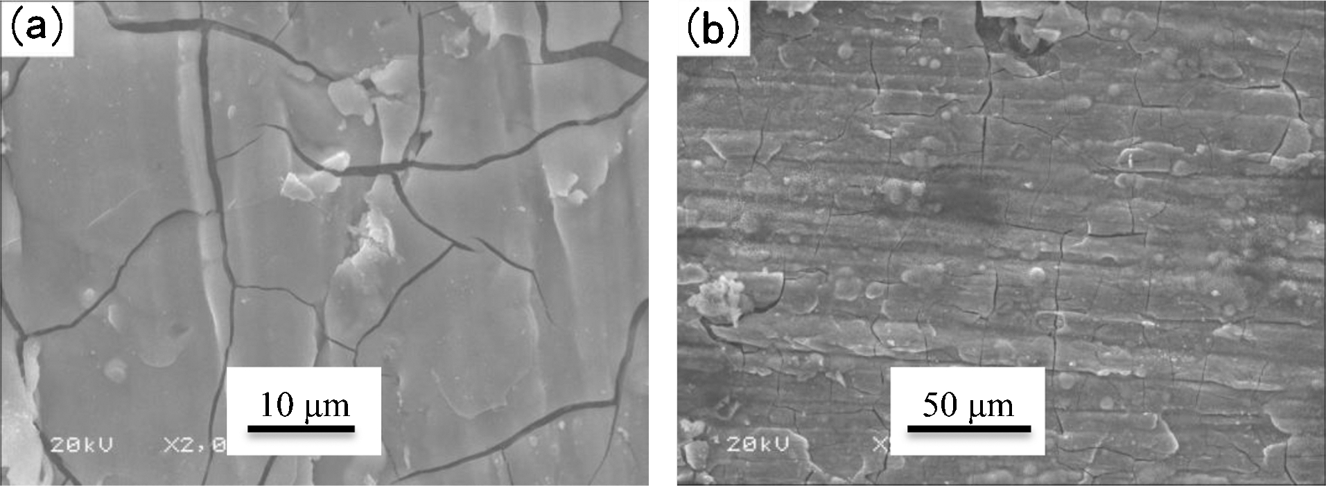
Surface morphology of rare earth conversion film before and after immersion in 3·5 wt-% NaCl solution
Molybdate and molybdate/permanganate conversion coatings
Molybdate and molybdate/permanganate conversion coating is also a conversion coating treatment for Mg–Li alloys. 171 These treatments are more environmentally friendly and offer an alternative to conventional chromate conversion coatings. Figure 45 shows the surface morphology of Mg–8·5Li alloy after molybdate (Fig. 45a ) and molybdate/permanganate (Fig. 45b ) conversion treatment in different solutions. The coatings nearly covered all over the surface of the alloy, while some cracks can be seen on the coating. The molybdate/permanganate conversion coating showed compact double layer with the appearance of cracks. MoO2, MgO, (MoO3)x(P2O5)y and MoO3 were the main compositions of the molybdate conversion coating. The optimum concentration of ammonium molybdate was 14 g/L. The molybdate conversion coating had better corrosion resistance. MoO2, MgO, Mn2O3, MoO3, Mn3(PO4)2, MnO2 and (MoO3)x(P2O5)y were the main compositions of the molybdate/permanganate conversion coatings. The molybdate/permanganate conversion coating had better corrosion resistance than the molybdate conversion coating when the concentrations of permanganate and molybdate were 3·5 and 14 g/L, respectively.
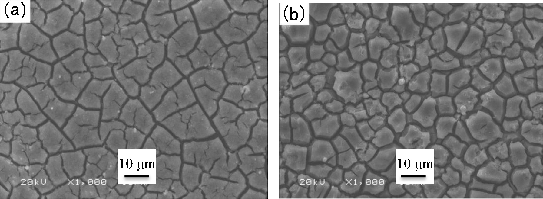
Surface morphology of molybdate (a, 14 g/L) and molybdate/permanganate (b, 14 g/L molybdate+3·5 g/L permanganate) conversion coating
Stannate conversion coatings
Stannate conversion coatings have been developed to protect conventional Mg–Li alloys 122,172–174 since they are environmentally acceptable. Recently, stannate coating was formed on Mg–8Li alloy by the simple immersion method.
After mechanical finishing, alkaline wash, and pickling, the Mg–Li alloys samples were immersed in a stannate bath for selected periods of time. The treatment gains a 2–3 mm thick, adherent and continuous crystalline coating of MgSnO3 on Mg–Li alloys. There was an increase in the corrosion potential of the Mg–Li alloys substrates during the formation of the stannate coatings, indicating that the coatings have a passive effect on the surface. Yang et al. reported that the coating particles were mainly composed of hemispherical particle shapes of MgSnO3·3H2O. 175 The treatment time influences the quality of stannate conversion coatings. The stannate coatings treated for 60 min are the densest and uniform, leading to excellent corrosion resistance in their studies.
Anodising
Anodising is an electrolytic process for producing a thick, stable oxide film on metals and alloys. 157 The coatings of anodic oxidation have many virtues, such as excellent binding strength to the substrate, excellent corrosion resistance, and wear resistance. They also provide an excellent base for further organic coatings.
The quality of the anodic oxide coating is influenced by the following: the components and concentration of the electrolyte, the type of the electric parameters, the temperature of the solution, the pH value and electrolyte time, and the components of the electrolyte are the most important. There are reports that the F− in the bath can change the texture and colour of the anodic oxide coating, but its thickness is unchanged; and the borate in the bath has influence on the thickness of the anodic oxide coating. Phosphate in the bath makes the film more uniform. The compactness of anodic oxidation coatings decreased with increasing operating temperature. The thickness of the anodic oxidation coatings increased with the pH value and the operating temperature increasing. The stages for processing include: 157
mechanical pre-treatment,
degreasing, cleaning and pickling,
electrobrightening or polishing,
anodising using d.c. or a.c. current,
dyeing or post-treatment, and
sealing.
Anodic oxidation mechanism
The surface appearance of the anodised coating was as given in Fig. 46: (a) distinct rough surface with cracks and large pore; (b) uniform, cracks and less porous; (c) homogeneous, no cracks and less porous; and (d) uniform, cracks and large porous.
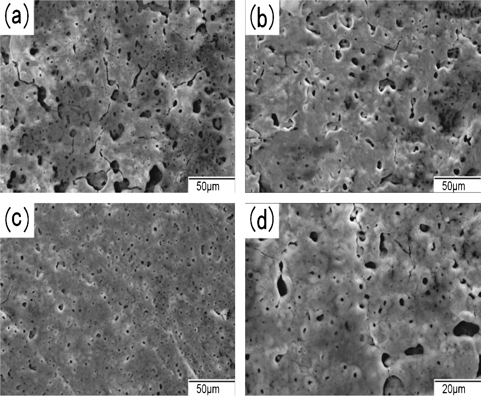
Surface morphology of anodic film with different deposition time: a 5 min; b 10 min; c 20 min; d 30 min
The formation of non-uniform and porous surface morphology of the film is caused by non-uniform sparking occurring on alloy surface, previous oxide on Mg–Li alloy surface melting, and gas evolution during the anodising process.
The coating layers cover the Mg–Li alloy substrate uniformly and compactly, but there were many micropores on the substrate. During the anodic oxidation process, there is gas evolution. When the maximum voltage was reached, there were sparks emerged on the surface of Mg–Li alloys, and then a large amount of heat was released. Because the heat was absorbed by the solution, the anodic oxidation film contracted. This brings about the porous structure. From a microcosmic aspect, although the thickness of the anodic oxidation film was unformed, the substrate’s chemical properties and electrochemical properties were not even. Consequently, the growth of the layer was not balanced and the distribution of the pores was also not balanced because the coatings have porous structure that could be coloured and sealed. The pore sizes are determined by the type of temperature, current density, applied voltage, electrolyte and its concentration. The pore size and density determine the quality and extent of sealing of the anodised coating. 157 These coatings may be used to improve paint adhesion to the metal, as a passivation treatment or as a key for dyeing.
When the alloy is connected to a stainless steel cathode and immersed in the anodising solution, the magnesium–lithium alloys surface dissolves to a small extent in the solution, and current flows from the Mg–Li alloy to the stainless steel. The films have a thin barrier layer at the metal–coating interface followed by a layer that has a cellular structure. The electrochemistry of the coating deposition can be represented in the following equations.
Anodic reactions:

Black anodising of a magnesium–lithium alloy
Sharma et al. 176 prepared coatings in a wide range of concentrations (20–30 g/L of each constituent) and electrolyte pH (0–6·0) using the process of black anodising on Mg–Li alloy. The research results indicate that proper heat treatment could improve the microhardness of the anodised coating. The hardness of the coatings increases with increasing electrolyte concentration at first, and then decreases. The anodised coatings not only improve thermal emittance (>0·90) and solar absorptance but they can also minimise temperature gradients across the specimens. This is suitable for a particular application on the internal components of spacecraft. The pre-treatment of the black anodising of an Mg–Li alloy includes polish to obtain an even surface→flush with tap water→alkaline cleaning→flush with distilled water→acid pickling→flush with distilled water→anodising. In general, the black anodic coatings on Mg–Li alloys were obtained with the following steps:
Solvent degrease: ultrasonic solvent degreasing in isopropanol for 5–10 min.
Alkaline cleaning: 50 g/L NaOH, 10 g/L Na3PO4′12H2O, 60±5°C for 5–10 min with a post-treatment water rinsing.
Acid pickling: 500 g/L CrO3, 1 g/L Fe(NO3)3·9H2O, 0·5–1·0 g/L KF, 24°C for 3–5 min with a post-treatment water rinsing.
Fluoride activation: 40% HF (50 mL/L) for 10 min, followed by water rinsing.
25 g/L K2Cr2O7, 25 g/L (NH4)2SO4, pH 4·5, 24°C, cathode anodising tank (stainless steel), current 0·45–l.20 mA cm−2, voltage 0·50–3·00 mV cm−2, current 0·45–l.20 mA cm−2, voltage 0·50–3·00 mV cm−2, 60 min.
Colouring and sealing of anodised coatings
Colouring of anodised coatings
Colouring of anodised coatings can be achieved by three kinds of methods: (1) absorbing inorganic pigments/organic dyes into the coatings immediately after anodising, (2) integral colour anodising, and (3) electrolytic deposition of inorganic metal oxides and hydroxides into the pores of the coating. The latter is achieved by adding organic constituents to the anodising electrolyte that decomposes during the process and forms particles, which become trapped in the coatings. 157,177 The colour may also be controlled by interference colouring. Interference colouring involves control of the pore structure to produce colour by interference of the light reflected from the top and bottom of the pores. 177
Sealing of anodised coatings
The anodised coatings of the Mg–Li alloys are porous. In corrosive environments, the corrosive liquid could penetrate through the pores to the substrate. So, the life of the coating could be decreased. Sealing of the anodised coating is necessary in order to achieve a corrosion- and abrasion-resistant coating. The porous oxide coating is sealed off by the precipitation of hydrated base metal species inside the pores. This can be accomplished by boiling in steam treatment, hot water, lacquer sealing and dichromate sealing. 35 These coatings are often inadequate as the only surface treatment, and they provide an excellent paint base for a corrosion protection system.
Some researches on the anodising of Mg–Li alloy
Li et al. 178 examined the possibility of producing anodic oxidation coating on the surface of Mg–10·02Li–3·86Zn–2·54Al–1·76Cu. The anodic oxidation coating was obtained in a solution of K2Cr2O7+H2SO4 through galvanic anodising. It was found that the alloy displays corrosion-resistant behaviour. The coating thickness increases with an increase in operating temperature and a decrease in pH value. The results show that an optimum corrosion resistance can be obtained by coating at room temperature with pH 4·5 or 5·5.
Recently, the influence of silicon sol on the anodic oxidation coatings of Mg–Li alloys was also studied since the silicon sol has many special characteristics. For instance, the nanoscale micellae of the silicon sol has large specific surface area and better absorption ability, providing good cohesiveness. Also, the silicon sol is hydrophilic and oleophobic, which can be diluted to any concentration. When the silicon sol was added in the electrolyte, the diameter of the pores became smaller and the coating became denser. During the experimental process, the brightness became larger and the reaction became more severe as compared with the ones without silicon sol. It can be recognised that the addition of silicon sol could accelerate the formation of coatings. Thus, a uniformed and corrosion-resistant coating can be obtained.
The effects of phytic acid on the anodic oxidation coatings of Mg–Li alloys were also investigated. Phytic acid has special molecular structure, physical and chemical properties and is non-toxic. It is an environmentally friendly corrosion inhibitor. Phytic acid can react with Mg–Li alloy forming a dense, monomolecular film on the surface of the substrate. This film could prevent the corrosive medium from penetrating into the substrate. The anodic oxidation coatings of Mg–Li alloy became whiter and smoother, and the corrosion resistance of the coating was increased.
Micro-arc oxidation
Micro-arc oxidation 179–181 has been applied in the surface modification of metals such as Ti, Al, Mg and some alloys. Micro-arc oxidation is also called microplasma oxidation (MPO) or anode spark deposition (ASD). In general, the process of MAO is carried out by putting aluminium, magnesium and titanium or their alloys in electrolyte solution.
Recently, MAO was applied in the coating of Mg–Li alloys in Na2SiO3 solution system. It was found 182–184 that the coatings doped with triethanolamine, glycerol, Na2EDTA or Na2B4O7 could improve the corrosion resistance and microhardness. Guo and An 185 and Abbasian et al. 186 proposed that many surfactants could be widely used as foaming agents, dispersing agents or wetting agents to improve the coating quality, or to inhibit defect development. Shi et al. 187 selected two kinds of additives (Na2B4O7 and EDTA) and a solution of Na2SiO3–Na3PO4 for preparing the ceramic coatings by MAO. The effects of the additives on the corrosion resistance and structure of ceramic coatings were studied. It was found that the coatings were composed of Mg2SiO4 and MgO. The coatings had a porous surface structure. Doping of additives influenced the morphological feature of the coating, but there was only little effect on the elemental composition. The results of electrochemical tests showed that the MAO coatings prepared in the solutions containing additives had good corrosion resistance. The addition of EDTA in the solution makes coatings more uniform and thinner, whereas Na2B4O7 makes the coatings much thicker and more compact.
Coatings
When Mg–Li alloys are exposed to non-corrosive or mild environments, Mg–Li alloys could also be corroded since the Mg–Li alloys are very active. 188–193 In the above sections, they have introduced some surface protections for Mg–Li alloys, including anodising, conversion coatings, organic coatings, electroless plating and PVD. 174,194–196 These processes provide limited corrosion protection for Mg–Li alloys. The organic coatings on Mg–Li alloys 197 only offer temporary protection. The other methods involve immersing Mg–Li alloys into a corrosive solution, forming a coating to protect the Mg–Li alloys. 198,199
ZSM-5 zeolite coatings onto Mg–Li alloys
Zeolites have been called excellent ‘building blocks’ for constructing hierarchical porous materials. They can be a component for functional coatings, such as low dielectric constant coatings for generating computer chips in the future. 164,200–202 Zeolites are a class of microporous crystalline aluminosilicates. High-silica or pure silica zeolites are especially known for their high chemical, thermal and mechanical stability. 203 ZSM-5 does not lose its crystallinity up to 1100°C. It does not react with any mineral acid except hydrofluoric acid. 204 ZSM-5 zeolite coatings formed by in situ crystallisation appear to offer general corrosion protection for the Mg–Li alloys. The method of hot pressing was used to assemble ZSM-5 zeolite involving the synthesis with two kinds of organic amines as templates on the surface of Mg–Li alloy. The organic amines of tetrapropylammonium bromide and tetrapropylammonium hydroxide as macromolecular templates were used to synthesise ZSM-5 zeolite. The micropores of ZSM-5 zeolite were blocked by organic templates, which enhanced the corrosion resistance of ZSM-5 coatings.
Cheng et al. 205 reported a novel approach to hot pressing to assemble ZSM-5 coatings on Mg–Li alloy. X-ray diffraction patterns and SEM images showed that ZSM-5 coatings are uniform and compact. ZSM-5 exhibits a pure MFI structure. The results of immersion and electrochemical tests indicated that ZSM-5 coatings improved the corrosion resistance of Mg–Li alloy because the templates block the pores of ZSM-5.
Diamond-like carbon coating on Mg–Li alloy
Diamond-like carbon (DLC) coatings on Mg–Li alloys have been investigated to improve the wear and corrosion resistance of the material. 206 Both deposition of a silicon (Si) interlayer and mechanical pre-treatment were applied to improve adhesion, before coating with the DLC film. 207
Yamauchi et al. 208,209 studied the effectiveness of DLC coating technology in improving the wear and corrosion resistance of the Mg–14 mass-%Li alloy. The effects of two different pre-treatment methods were examined. One is coating with a Si interlayer using the ion beam sputter method and another one is peening specimens using a silicon carbide (SiC) medium before the deposition of the DLC film. The RF (Radio Frequency) capacitively coupled plasma CVD (Chemical Vapor Deposition) method was used for DLC coating in their experiments. The results indicated that the SiC peening process enhances the formation of DLC adhesive coating, leading to a relatively low wear and low friction coefficient. However, the DLC coating did not form adhesively on the substrate with a Si interlayer. Unfortunately, none of the DLC-coated specimens were able to withstand the corrosion effects of the alkaline and acidic artificial perspiration solutions.
HTMZ coating on Mg–Li alloy
A nano-sized lamellar molybdate pillared hydrotalcite/in situ created ZnO composite has been used to improve the corrosion protection for magnesium–lithium alloy. Molybdate is an excellent inhibitor of metallic alloy corrosion. 210,211 Nano zinc oxide can polarise cathode areas by precipitating soluble salts. 212,213 Consequently, molybdate pillared hydrotalcite/ZnO incorporated composites (HTMZ) have perfect anti-corrosion properties for Mg–Li alloy. While nano ZnO particles are an important factor controlling the corrosion inhibition by MoO4 2− ion, HT-MoO4 2− can release the MoO4 2− ion and trap the corrosive Cl− ion. 214
Yu et al. 215 has reported that nano-sized molybdate pillared hydrotalcite (HT-MoO4 2−)/ZnO incorporated composite (HTMZ) was successfully synthesised by an in situ coprecipitation method. A given amount of molybdate sodium was adjusted at pH 10·0 with NaOH and then mixed with a second solution to prepare the materials. The second solution contained Al(NO3)3·9H2O and Zn(NO3)2·6H2O with a metal ratio Zn2+/Al3+of 2·5. An epoxy resin coating containing HTMZ was formed on Mg–Li alloy. The research presents the comparative corrosion protection performance of the coating. Corrosion protection properties for Mg–Li alloy based on the HTMZ nanocomposite was investigated in NaCl solution by salt spray test and EIS. 216 The results indicated that coatings containing HTMZ have better corrosion-resistant property. The mechanism of corrosion protection was attributed to the existence of ZnO, thus promoting molybdate accumulation on the Mg–Li alloy substrate.
Prospects
Recently, Mg–Li alloys with the characteristics of low density, high strength and ductility have been obtained through suitable technologies of preparation and processing. Nowadays, some new properties and applications for Mg–Li alloys are being explored. However, because of the high chemical activity, low melting point, and the existence of hcp α phase, Mg–Li base alloys possess poor elevated-temperature properties. More important, it is hard to obtain high strength and excellent ductility simultaneously. Recently, an 18R type long-period stacking-ordered structure (LPSO) was proposed and prepared as an Mg–Li base alloy. 217 The results show that the LPSO can effectively improve both the strength and plasticity of extruded alloy, and the elevated-temperature mechanical properties are also improved. This is becoming a hot research point.
Because of the suitable degradation rate, Mg base alloys are becoming increasingly interesting materials for coronary stents to provide a temporary opening of a narrowed arterial vessel until the vessel remodels and then gradually disappear. 218 However, in addition to degradation rate, the mechanical properties of magnesium alloys designed for cardiovascular stent applications must meet the specifications of radially expandable stents. In general, magnesium alloys have very limited ductility at room temperature or at body temperature. The addition of Li can improve the ductility because of the variation of hcp structure parameters and the existence of bcc structure. 219 Therefore, Mg–Li base is a good candidate material for the application of coronary stents. 220
Metal-hydrogen peroxide semi-fuel cells exhibit many potential advantages, such as low cost, their environmentally benign behaviour, stable discharge voltage, high power density and high specific energy. This electrochemical system consists of a metal anode, a conductive membrane and a cathode catalyst. Mg as an attractive anode material has received recent attention because it has high Faradic capacity, high specific energy and a more negative standard reduction potential. As compared to common Mg base alloys, Mg–Li alloy anodes exhibit a higher anodic efficiency. 221 Especially, the Mg–Li/MgCl2/CuO battery can offer a higher operating voltage and capacity than that of batteries with an Mg–Al alloy anode. The electrochemical behaviour of Mg–Li alloy anodes is being investigated by many researchers. 222,223
To overcome the drawback of low strength, the non-crystallisation of Mg–Li base alloys have been prepared in recent years. Liu et al. 224 prepared new Mg–Li–Cu–Ni–Y BMG samples 2 mm diameter using a copper mould injection-casting method. Experimental results demonstrated that the as-cast BMG samples displayed higher strength, higher hardness and lower elastic modulus as compared with normal crystalline Mg–Li based alloys. Among these samples, Mg65Li2Cu18Ni5Y10 BMG possesses the most excellent mechanical properties, which has an ultimate compressive fracture strength of 729 MPa, the highest HV of 2·48 GPa, and a low elastic modulus E of 36 GPa.
Footnotes
Acknowledgement
This work was supported by the grants from NSFC (Nos. 51001034, 451171081, 51371062, 21173060, 91226201 and 21103033), the National High Technology Research and Development Program of China (863 Program) (No. 2011AA03A409), Heilongjiang Province Youth Skeleton Program (1252G018), Research Fund for the Doctoral Program of Higher Education (20132304110006), Project of Science and Technology of Heilongjiang Province Education Department (12511068), Harbin City Innovative Talents Research Special Program (2012RFXXG094), the Fundamental Research Funds for the Central Universities (HEUCFQ1416), Heilongjiang Province Natural Science Foundation (E201420) and Heilongjiang Postdoctoral Funds.