
Abstract
The processing of nanomaterials and nanocomposites has advanced since the 1990s. The growth and opportunities afforded by this technological domain is evident through the trends of research and development (R&D) funding, Science Citation Index (SCI) publications, and patent applications presented in this paper. This article reviews the current state for the development of thermal sprayed nanocomposite coatings. The types of nanocomposite thermal spray feedstock materials that are available commercially, as well as those currently in the development phase, are critically assessed. The thermal spray approaches to deposit nanocomposite coatings are discussed, including the conventional plasma spray and high velocity oxygen fuel (HVOF) processes and the more recently developed cold spray, suspension thermal spray (STS), and solution precursor thermal spray (SPTS) processes. These processes are assessed in relation to their deposition mechanisms and the specific nanocomposite materials associated with each technique. The unique microstructure of the coatings deposited by each method is highlighted in relation to process and compositional control. The exceptional attributes of nanocomposite coatings, such as mechanical strength and toughness, wear resistance, thermophysical, and electrical properties, are also presented together with specific applications.
Introduction
Nanotechnology and nanomaterials
The concept of nanotechnology has emerged since 1959 when the Physics Nobel Laureate, Richard Feynman gave his renown talk ‘There's Plenty of Room at the Bottom’. 1 However, it was not until the early 1980s that the prospects of atomic-scale control of materials became prominent through the development of a conceptual framework for nanotechnology 2 and technological advances such as the invention of scanning tunnelling microscopy 3 and the discovery of fullerenes. 4 The research and development (R&D) in nanotechnology accelerated in 2000 when the definition and long-term vision of nanotechnology was defined by the United States National Nanotechnology Initiative. 5
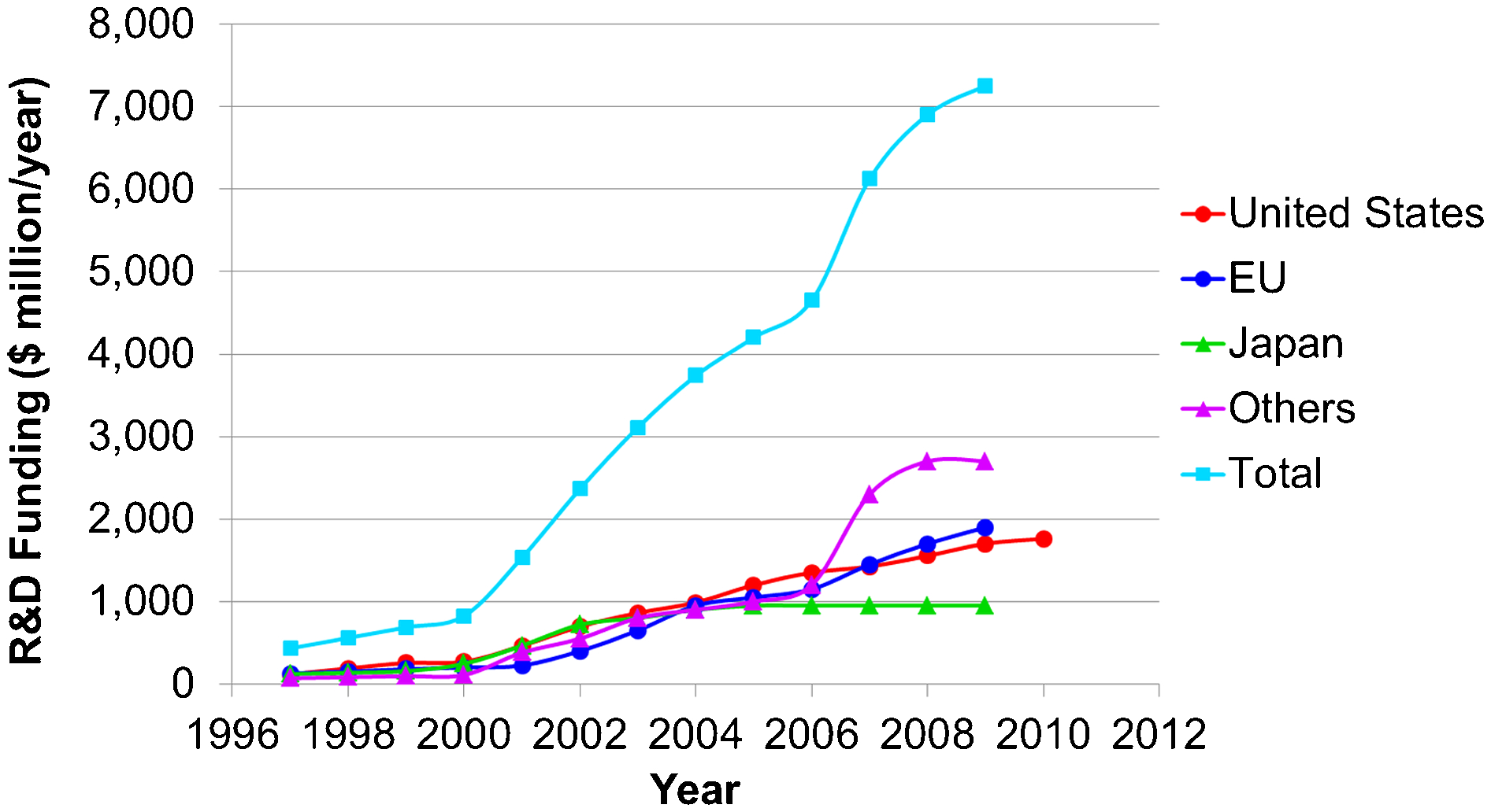
This advancement immediately sparked the establishment of sustained nanotechnology R&D by Japan, Korea, the European Community, Germany, China and Taiwan. 6 Figure 1 shows the growth of the national funding on nanotechnology R&D for several countries since the mid-1990s. More detailed information and analyses on the trend of R&D funding on nanotechnology, including funding by public and private sectors across different countries and their projected growth until 2015, can be found in Refs. 6 and 7.
The European Commission defined nanomaterials as ‘a natural, incidental or manufactured material containing particles, in an unbound state or as an aggregate or as an agglomerate and where, for 50% or more of the particles in the number size distribution, one or more external dimensions is in the size range 1–100 nm. In specific cases and where warranted by concerns for the environment, health, safety or competitiveness the number size distribution threshold of 50% may be replaced by a threshold between 1 and 50%.’ 8 In other words, nanomaterials display a structure with at least 50% (by number) of a material with at least one dimension smaller than 100 nm. Note that before the widespread use of the term nanomaterial or nanoparticle, materials in the nano-sized range; i.e. less than 1 μm, were referred to as ultrafine or sub-micrometre particles. 9–11
Nanomaterials can be classified according to their geometric dimensions; i.e. the number of dimensions that are not confined to the nanoscale range. 12 The four classifications of nanomaterials are (i) zero-dimensional (0D), where all three dimensions are within the nanoscale, such as nanoparticles or nanoclusters; (ii) one-dimensional (1D), where only two dimensions are within the nanoscale, such as nanotubes or nanowires; (iii) two-dimensional (2D), where only one dimension is within the nanoscale, such as thin films or nanoplates; and (iv) three-dimensional (3D), where none of the bulk dimensions are within the nanoscale but the constituents within the material have nano-characteristics, such as nanocrystalline and nanocomposite materials; Fig. 2.
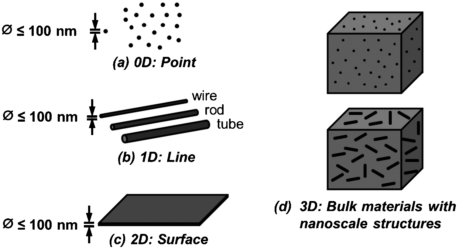
Classification of nanomaterials: a zero-dimensional, b one-dimensional, c two-dimensional, and d three-dimensional nanostructures. Please note that ø and t represent the diameter and thickness, respectively
Nanomaterials demonstrate unique optical, 13,14 thermal, 15,16 mechanical, 17,18 electrical, 19,20 and magnetic 21,22 properties that are not exhibited by their bulk counterparts. The attributes of nanostructured materials that are size-dependent arise from (i) surface effects due to a significant increase of surface-to-volume ratio and (ii) quantum effects due to confinement of electron movement, changes in the electronic structure and interatomic relation, and the presence of defects. 12,23 Nanomaterials have found many practical applications in industry that range from electronics to aerospace, Table 1.
General applications of nanomaterials
Generally, there are two approaches to produce nanostructured materials: (i) the top-down and (ii) the bottom-up approaches. The top-down approach involves the breakdown of a bulk material structure to reduce the crystal size to sub-micrometer or nanoscale. On the other hand, the bottom-up approach involves processing or building up a material from the atomic scale or nanoclusters in a way that retains the original nanoscale structural units. Examples of these two approaches are outlined in Fig. 3. This review concerns the deposition of nanocomposites via thermal spray route, which is a bottom-up approach. It might be argued that the impact process experienced during the formation of a thermal spray coating will cause fragmentation of micrometre-sized particles to the nanoscale; i.e. a top-down approach. However, as this is not the preferred formation process that would retain a lamellar structure, then the bottom-up approach is considered as the dominant mechanism.
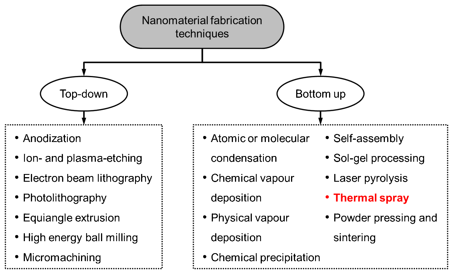
The top-down and bottom-up approaches for nanomaterials fabrication
Nanocomposites
Nanocomposites are multiphase materials that are composed of two or more substances, of which at least one has a nanoscale dimension. 24 The multifunctional potential of nanocomposites is manifested through combinations of the distinctive properties of each phase that act synergistically to create properties that would not otherwise be achievable. Naturally occurring nanocomposites are formed through self-organisation and directed assembly of macromolecules, inorganic materials or a combination of both in biological systems. 25 Examples of natural nanocomposites include tooth enamel, bone, the aragonitic nacreous layer of abalone shell, dragline spider silk, magnetic bacteria, and sea urchin spines. 25 These naturally occurring nanocomposites exhibit unique properties that are not found in synthetic materials, leading to efforts to understand the design of biological systems and create biomimetic materials such as bone scaffold and nanofibers. 26
Current and potential industrial applications of nanocomposites include, among others, the field of aerospace, 27 automotive, 28 biomedical, 29,30 electronics, 31 energy storage, 32,33 food packaging, 34 functional textiles, 35 manufacturing, 36,37 optics, 38 and photocatalysis. 39 The primary challenges in commercialisation of nanocomposites lies in (i) achieving precise control over the size distribution and dispersion of the nanoscale constituents for large-scale manufacturing and processing and (ii) understanding the functional roles of the interfaces between structurally and/or chemically dissimilar phases on the bulk material properties. Much research has been carried out to address these issues and explore the functionalities of nanocomposites. The development of nanocomposites can be seen worldwide, as evidenced through the increasing growth of Science Citation Index (SCI) publications and patent applications in the past 25 years; Figs. 4 and 5.
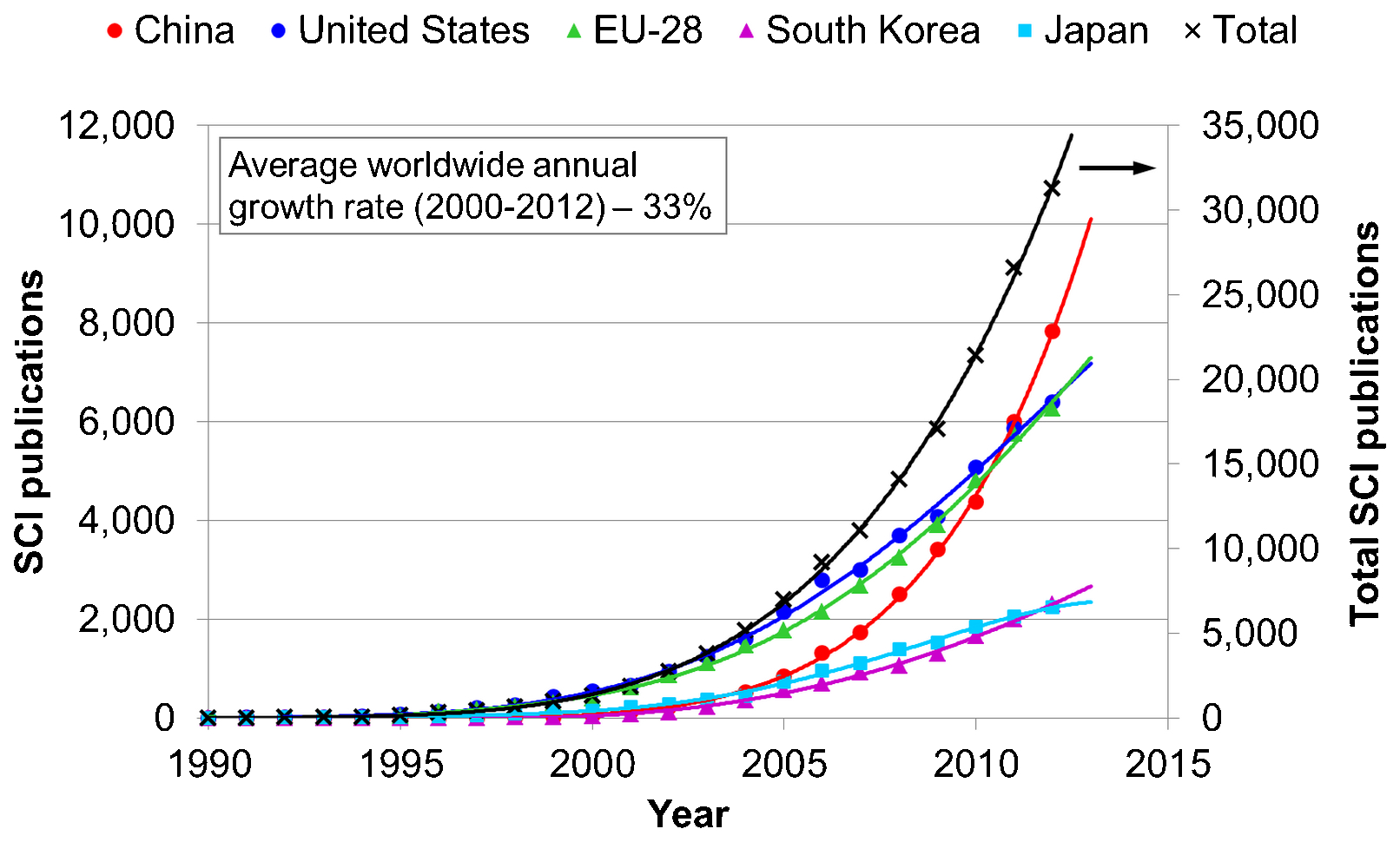
Nanocomposite publications in the Science Citation Index (SCI) from 1990 to 2012 for the five leading countries/territories. The data were generated from an online search in the Web of Science using a ‘title-abstract’ search in the SCI database for nanocomposite
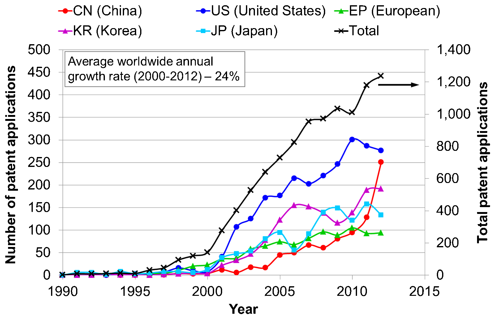
Nanocomposite patent applications from 1990 to 2012 for the five leading patent offices of China (CN), United States (US), European (EU), Korea (KR), and Japan (JP). The data were generated from an online search in LexisNexis TotalPatent using a ‘title-abstract-claims’ search for nanocomposite
The upsurge of interest and research activities in the area of nanocomposites are indicated in the number of SCI publications, which reached a total of over 31 000 worldwide in 2012 compared to 1 319 in 2000. This growth is rapid and irregular around the world, with the five leading regions contributing to over 80% of the total publications; Fig. 4. The inventions related to nanocomposites are represented by the number of patent applications filed in the patent repositories worldwide. There were over 1 200 applications filed in 2012 worldwide compared to 142 in 2000. Over 75% of these patents were filed in the top five leading patent offices; Fig. 5. These statistics reflect the rapid development of nanocomposites since 2000, where the number of SCI publications and patent applications show average annual growth rates of 33 and 24%, respectively.
Despite their advantages, bulk nanocomposites can be expensive to produce because of the production costs of nanomaterials and technical limitations in preserving a nanostructure in the consolidated product due to excessive grain growth. 40 Nanocomposite coatings use lesser amounts of nanostructured materials because they are quite thin; i.e. several micrometres up to a millimeter depending on the deposition technique, and can potentially cover large areas. Therefore, nanocomposite coatings present an effective alternative to take advantage of the many remarkable properties of nanomaterials without bearing the production costs of bulk nanocomposites. There are two types of nanocomposite coatings: (i) matrix-reinforced, where the reinforcing phase is within nanoscale, and (ii) layered coatings, where the thickness of individual layers are within nanoscale dimensions; Fig. 6.
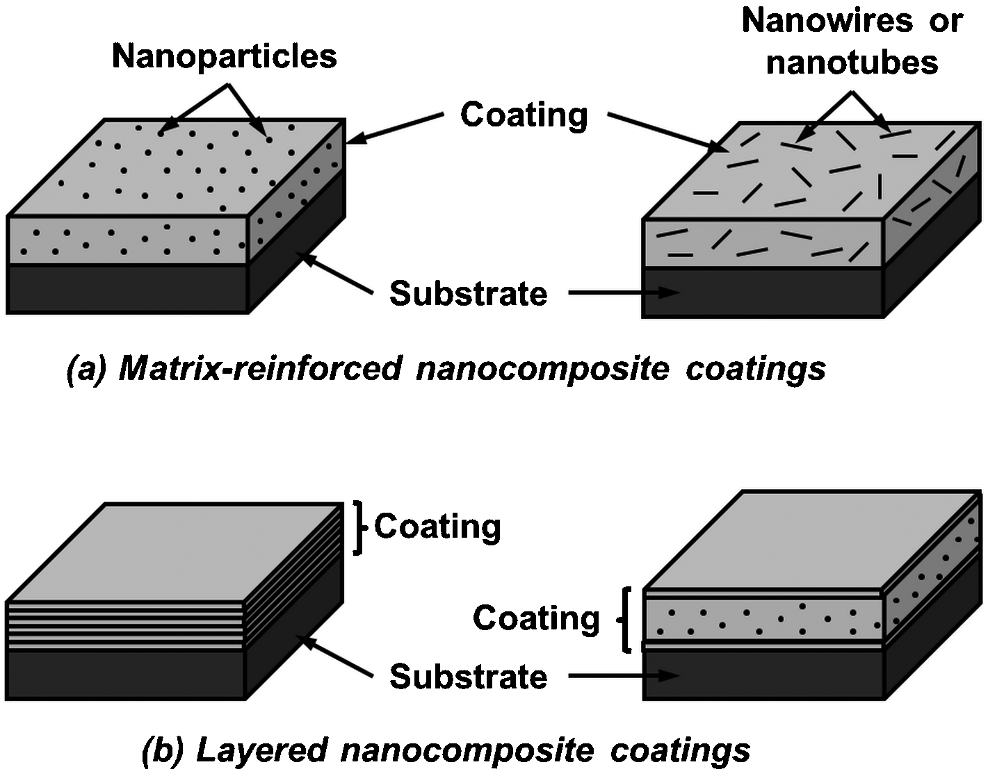
Schematics of nanocomposite coatings: a matrix-reinforced and b multi layered
Deposition of nanocomposite coatings is a bottom up approach of producing nanomaterials. There are various techniques that can be used to manufacture nanocomposite coatings, depending on the thickness, structure, purity, crystallinity, costs, and/or materials considerations. These techniques can be classified into (i) physical methods; e.g. cathodic arc deposition, 41 electron beam evaporation, 42 pulsed laser deposition, 43 sputter deposition, 44 ion implantation-deposition process, 45 and thermal spray processes; 46 and (ii) chemical methods; e.g. chemical vapour deposition (CVD), 47 electroplating, 48 self-assembly, 49 spin coating, 50 and sol-gel dip coating. 51 Following deposition, the coatings can undergo post-deposition treatment and/or surface patterning as required for specific applications.
Thermal spray nanocomposite coatings
Thermal spray is a generic term referring to a group of coating processes in which a stream of finely divided metal or non-metal particles is melted and propelled towards a substrate to form flattened lamellae that stack progressively to form a coating. 52,53 Thermal spray composite coatings have long been established as high performance functional coatings for applications such as wear resistance, corrosion resistance, abradable seals, and thermal barriers. 54–57 These coatings include a variety of metal-matrix, 58–60 ceramic-matrix, 61,62 and polymer-matrix 63,64 composites. Thermal spray fibre-reinforced coatings have also gained much attention since the 1980s. 65–67 Thermal spray processes present a versatile approach for deposition of nanocomposite coatings in terms of materials, deposition medium, and thickness compared to other deposition processes.
A wide range of materials can be deposited using thermal spray processes because of its wide range of processing temperatures and velocities. Thus, any composition of materials can be combined and deposited by thermal spray to synthesise composites with optimised properties; e.g. high melting point ceramics and low melting point polymers. Thermal spray nanocomposite coatings are much thicker than those achievable by other methods; e.g. physical and chemical vapour deposited films are typically <5 and 0·1 to 500 μm thick, respectively. The thickness of thermal spray coatings range from 50 μm to several millimetres, although thinner coatings of ∼10–50 μm are possible with liquid thermal spraying.
Thermal spray processes are economically advantageous compared to other deposition methods because of (i) high deposition rate, namely <5 μm h−1 for physical vapour deposition (PVD) 68 and <200 μm h−1 for plasma-assisted CVD 69 compared to >1 000 μm h−1 for plasma spray; 70 (ii) low starting materials, equipment, and operating costs; (iii) flexibility of deposition medium; and (iv) optional substrate pre-heating. The waste disposal systems of thermal spray processes are simple and less hazardous compared to processes such as CVD and electrodeposition.
Thermal spray processes have the unique capability for dimensional restoration of damaged or worn out engineering and structural components without needing to replace the whole component. This presents a sustainable approach for incorporating nanocomposite materials as thermal barrier, wear resistant, corrosion resistant, and abradable coatings. The portability of thermal spray equipment is an advantage for on-site repair of large or immobile components. Thermal spray can, therefore, be considered as an additive manufacturing technology.
The basic structural building blocks of thermal spray coatings are splats, which are formed by the flattening of molten particles upon impact. Depending on factors such as the degree of particle melting and impact velocity, the microstructure of thermal spray coatings is typically porous, anisotropic, and may comprise microcracks, unmelted particles, and oxide inclusions. Such porous and lamellar structures are distinct from the dense columnar and/or equiaxed structures formed by atomistic deposition processes such as PVD, CVD, and ion implantation-deposition. 69,71 Electroplated coatings exhibit grains with preferred orientation that depend on the material, electrolyte composition, deposition conditions, and substrates. 72 The microstructure of sol-gel coatings derived through dip coating or spin coating range from porous, weakly branched polymers to highly condensed particles, depending on the structure of the entrained inorganic species in the original sol, their reactivity, the timescale of the process, and magnitude of shear and capillary forces. 73
Novel and advanced nanocomposite coatings with unique compositions and properties can potentially be deposited via thermal spray routes through the incorporation of metastable and amorphous phases formed by rapid cooling of the materials; namely 105–108°C s−1. 52 Oxide-free deposits can be produced using low pressure plasma spray and cold spray, while combinations of a wide range of oxide, carbide, and nitride nanocomposites are possible through atmospheric plasma spray or through proper control of the oxygen–fuel ratio in combustion thermal spray systems. Grain growth during thermal spray processes is restricted because of the high solidification rate; thereby enabling formation of a nanocrystalline structure.
Owing to the nature of the deposition process, thermal spray coatings exhibit randomly distributed splats. Thus, there is a random phase distribution in nanocomposite systems, which is favourable in certain applications; e.g. randomly distributed (∼15%) amorphous calcium phosphate and α-tricalcium phosphate in hydroxyapatite biomedical coatings resorb preferentially to promote implant fixation. 74 The variation of feedstock particle size distribution and morphology contributes to structural and compositional inhomogeneity in thermal spray coatings. This is especially true for nanocomposite systems because the melting and reconsolidation of feedstock materials are restricted. Therefore, the compositional homogeneity of nanocomposite coatings is reflected in the homogeneity of the original feedstock.
In terms of its limitations, the thermal spray process is a line of sight process, which infers that expensive, automation systems are necessary for deposition onto complex geometries. Thermal spray coatings are porous, exhibit relatively low bond strength, and low loading capacity; although these microstructural/properties aspects tend to improve for nanocomposite coatings. Thermal spray coatings are also anisotropic because of the lamellar structure of the coatings; i.e. properties on the plane parallel to the coating surface are significantly different from that on the plane perpendicular to the coating surface. In depositing nanocomposite coatings, there is a possibility of materials degradation and loss of nanostructure because of the high temperature process. However, such technical detriments can be overcome through control of the spray process parameters.
Specific topics of prior review articles related to thermal spray and nanostructured coatings are summarised in Table 2. Thermal spray processes and nanocomposites have been reviewed independently previously. The intent of the current article, therefore, specifically reviews nanocomposite coatings that are deposited by thermal spray processes in relation to their processing, microstructure, and performance. The feedstock materials for thermal spray can be in the form of powder, wire, or liquid, and the ‘Feedstock Materials’ section of this review paper is dedicated to the production and characteristics of these materials.
Selected review articles related to thermal spray processes and nanostructured coatings
‘The thermal spray deposition: process and microstructure’ section presents the formation mechanisms and the nano/microstructure of nanocomposite coatings manufactured by conventional thermal spray processes as well as modern processes such as cold spray, suspension and solution precursor thermal spray (SPTS). Prominent nanocomposite materials deposited by thermal spray are assessed in the ‘Nanocomposite coatings’ section, with emphasis on process dependent phase transformations, and their correlations with nano/microstructure and properties of the coatings. The properties and applications of selected nanocomposite coatings with a view towards future potentials are presented in the ‘Properties and potential applications’ section.
Feedstock materials
The three prime forms of feedstock that are used to manufacture thermal spray nanocomposite coatings are (i) powder, (ii) wire, and (iii) liquid. Powder feedstock is the most commonly used because it is compatible with most conventional feeding systems and spray processes. However, nanoparticles present difficulties in terms of handling and feeding. Therefore, nanoparticles must be processed to microscopic size; i.e. to a 3D morphology, when used as thermal spray feedstock. Nanocomposite wire feedstock is available commercially in the form of cored wire, where the core is made of agglomerated nanoparticles in a metallic sheath. Although still being in the R&D phase, liquid feedstock in the form of a suspension or solution precursor, is becoming a prominent route for producing nanostructured coatings. The precursor feedstock route has an ability to produce nanocomposite coatings in situ without the need for the extensive manufacturing steps required to produce powder and wire feedstock.
Agglomerated powder
Nanostructured powder can be manufactured through three main routes: (i) mechanical processing, (ii) chemical processing, and (iii) physical or thermal processing. Mechanical processing involves mechanically crushing or milling large particles to nanoscale. Chemical processing involves nucleating or precipitating nanoparticles from solution or slurry, with or without the occurrence of a chemical reaction. On the other hand, thermal processing involves condensation of nanoparticles through rapid cooling of a supersaturated vapour. The examples, advantages and disadvantages of each of these techniques are summarised in Table 3.
Summary of processes used to manufacture nanostructured powder
As-collected nanoparticles are not ideal as thermal spray feedstock because of the following technical concerns: (i) handling difficulty and health concerns; (ii) not free-flowing and a tendency to aggregate, resulting in pulsed feeding and/or clogging of the injection line and nozzle; and (iii) insufficient inertia and momentum to penetrate the core of the thermal spray jet and establish an optimum trajectory. Injection of nanoparticles into the jet core by boosting the carrier gas flowrate has the unintended consequence of destabilising the thermal spray jet, as the injection force needs to be similar to that imparted by the jet flow. 75
The universal solution to this impediment is to agglomerate the nanoparticles using an organic binder. 76 Spray drying produces microscopic particles with the ideal spherical morphology for thermal spray feedstock, while still retaining the nanostructure of the original particles. A suspension or slurry, which consists of dispersed nanoparticles in an organic binder, is atomised to form micrometre-sized droplets that are subsequently dried using hot air in a closed chamber. 77 Spray drying is an appropriate technique to produce nanocomposite powder because of flexibility in selection of the raw materials.
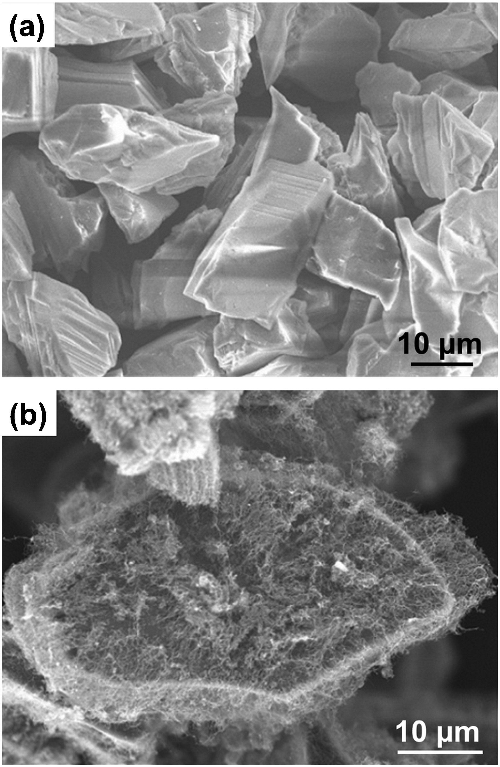
Spray dried particles are usually porous and weakly bonded, thus they do not exhibit adequate cohesive strength to withstand the turbulence of a thermal spray jet. The as-received particles are typically heat treated or densified using a flame or plasma process. 78 It is critical that the post-treatment is optimised to improve the cohesive strength of the particles and, simultaneously, retain their nanostructure characteristics. Figure 7 shows the morphology of a nanostructured yttria-stabilised zirconia (YSZ) particle (Nanox S4007, Inframat Corp., Farmington, CT, USA) agglomerated by spray drying. 79 Commercial nanocomposite powder produced via this route is often preceded by a low-cost milling operation to mechanically crush the particles to nano-size, and to uniformly mix different components of the composite together. Specific properties, such as toughness and ductility, can be imparted to the material by encapsulating the spray dried nanocomposite core into a thin (1–3 μm) metal coating to form a duplex structure (PComP, MesoCoat Inc., Euclid, OH, USA). 80,81
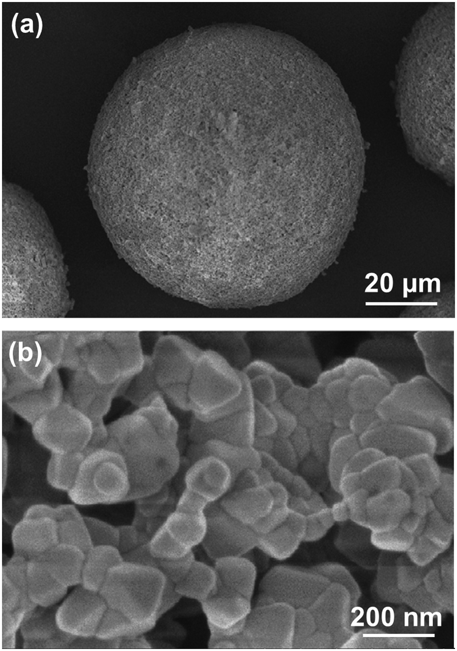
a Nanostructured yttria-stabilized zirconia (YSZ) particle agglomerated by spray drying and b higher magnification of the same particle highlighting the individual nano-sized YSZ particles. Reproduced from Lima et al. 394 with permission from ASM International
Another approach that has been used to consolidate nanoparticles for thermal spray feedstock is through suspension plasma spray (SPS). 78,82 Nanoparticle consolidation using a plasma source involves injecting a suspension of nanoparticles into a radio frequency (RF) plasma using a probe atomiser. The solvent vaporises as the suspension passes through the plasma source and the particles are collected using a series of filters. This approach combines processing steps such as drying, calcination, spray drying, spheroidisation and sieving into a single operation. Figure 8 shows the nanostructure of 40 wt-% zirconia–hydroxyapatite nanocomposite powder before and after consolidation by SPS.
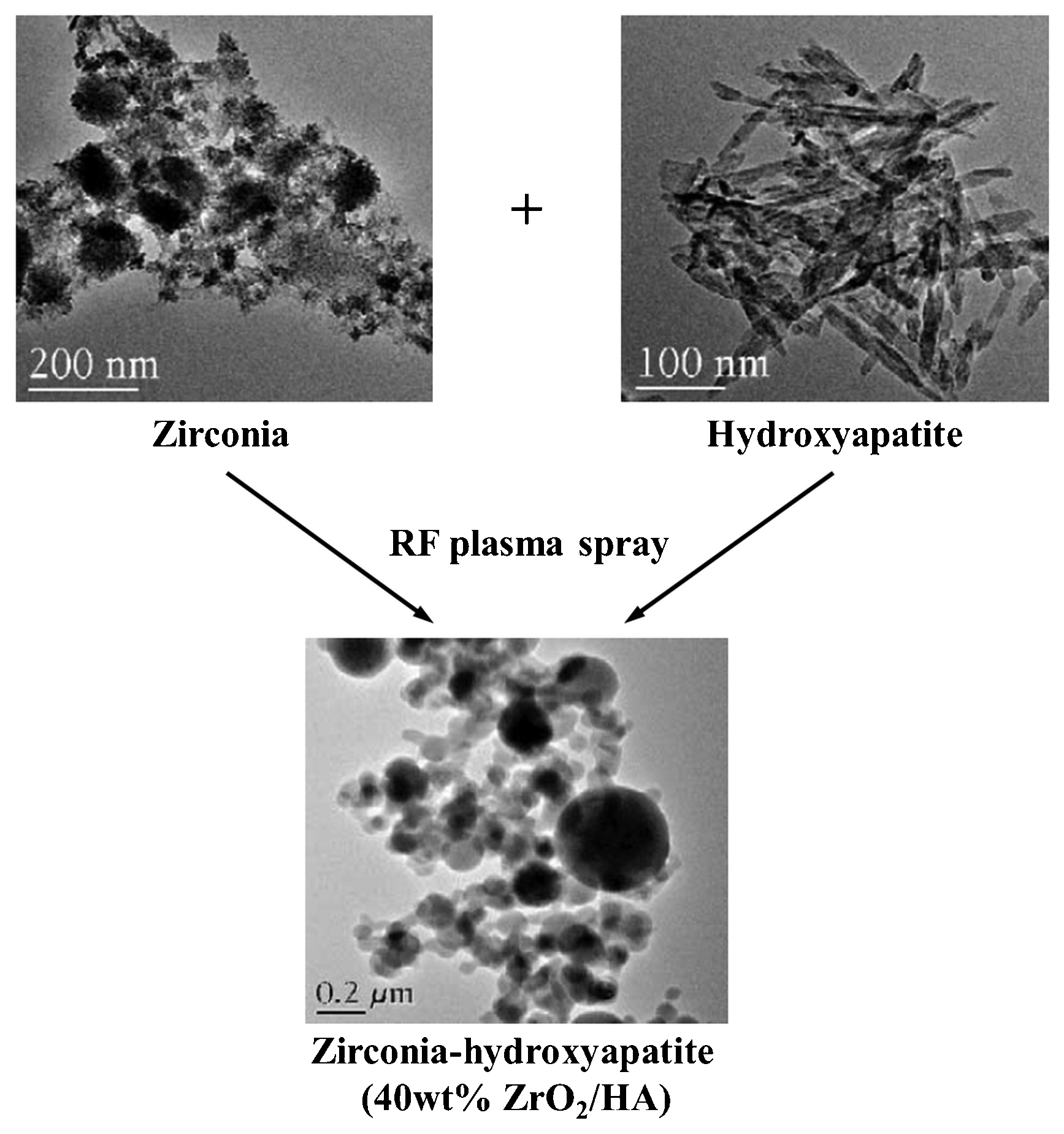
Transmission electron micrograph of zirconia–hydroxyapatite (40 wt-%ZrO2/HA) nanocomposite powder manufactured by suspension plasma spray (SPS). Reproduced from Kumar et al. 82 with permission from Elsevier
Nanoparticles or nanotubes can be introduced onto the surfaces of micrometre sized particles, rather than dispersing them within the particles, by mechanical or chemical means to produce nanocomposite feedstock. For instance, multi-walled carbon nanotubes (MWCNTs) were grown on the surface of stainless steel and alumina particles through catalytic CVD. 83,84 Figure 9 shows the morphology of carbon nanotubes (CNTs) incorporated onto the surface of alumina particles. In the mechanical approach, micrometre-sized particles were blended or milled with CNTs to disperse the nanotubes on the particle surface. 85
Incorporation of carbon nanotubes onto surface of alumina particles: a before and b after catalytic chemical vapour deposition. Reproduced from Balani et al. 84 with permission from Elsevier
Other less favoured methods that have been employed to produce nanocomposite powders for thermal spray feedstock include (i) single step homogeneous mixing of the nano-sized component with matrix material using ultrasonic 86 or milling 87 techniques, (ii) sol-gel synthesis, 88,89 and (iii) freeze drying. 90 However, these techniques produce particles with angular, irregular, or blocky morphology, a wide particle size range, and attending poor flowability. Figure 10 shows the particle morphology of Al2O3–SiO2 nanocomposite powders produced by sol-gel and freeze drying techniques. Grain growth inhibitors 91,92 can be introduced into nanocomposite powders to maintain the nanostructure during powder processing that involves heating, such as in sol-gel synthesis and thermal spraying. For instance, boron nitride may be uniformly dispersed as a grain growth inhibitor for WC–Co nanocomposite powders. 93
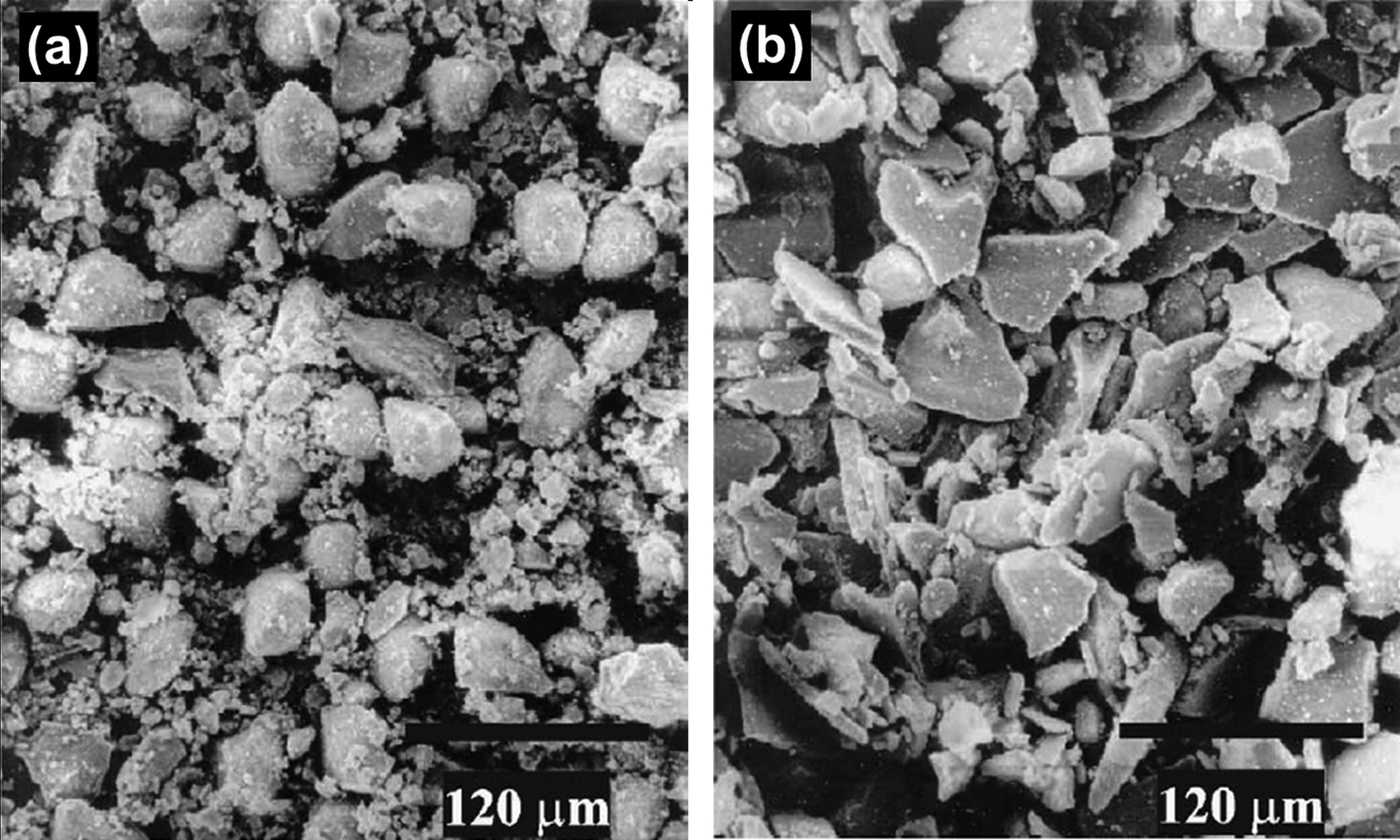
Scanning electron micrographs of Al2O3–SiO2 nanocomposite powder produced by a sol-gel and b freeze-drying techniques. Reproduced from Jiansirisomboon et al. 90 with permission from Elsevier
Despite the fact that thermal sprayed nanocomposite coatings have been reported since the late 1990s, 46 nanocomposite feedstock is limited commercially. Many reports on nanocomposite coatings have been produced in-house at the laboratory scale. Among the known suppliers of commercial nanocomposite feedstock are Inframat Corp. (Manchester, CT, USA), Millidyne Surface Technology (Tampere, Finland), and MesoCoat Inc. (Euclid, OH, USA). Agglomerated nanocomposite powders that are currently available commercially for thermal spray applications include Al2O3–TiO2, Al2O3–TiO2–CeO2, Al2O3–ZrO2–SiO2, Cr2O3–SiO2–TiO2, Cr2O3–TiO2, SiN–NiCr, TiN–NiCr, TiN–CoCrNiMo, WC–Co, WC–Co–Cr, WC–Ni, WC–Co–NiCr, WC–Co–NiCrFeSiBr, WC–Co–NiCrFe, ZrO2–MgO, ZrO2–Y2O3, and ZrO2–Y2O3–NiO.
Nano-cored wire
Despite being the preferred form of feedstock material because of their lower costs; ease of material storage and handling; high deposition rate; and high deposition efficiency, nanocomposite wire feedstock has little mention in the literature. Nanocomposite wires cannot be manufactured using the cold drawing or rolling techniques used for conventional wires, because these are limited to malleable and electrically conductive materials. Instead, nanocomposite wires are produced as cored wires, where a metallic sheath surrounds the core of nanoparticle agglomerates. 94,95 Figure 11 shows the cross-section and nanoparticle distribution in a nanocomposite cored wire. 96
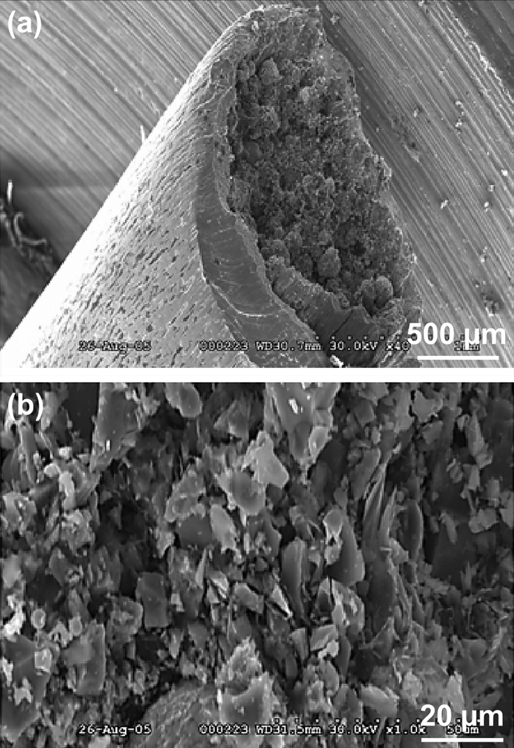
a Cross-section of nanocomposite cored wire (Praxair Surface Technologies Inc., Indianapolis, IN, USA) and b high magnification SEM micrograph showing the homogeneous distribution of nanocomposite particles within the cored wire. Reproduced from Georgieva et al. 96 with permission from ASM International
There are several variations of cored nanocomposite wires, characterised by the type and structure of the core filling and metal sheath materials. The construction of the simplest and most common cored wire is shown in Fig. 12a . Such cored wires are produced by first shaping a metal strip into a U-shaped tube. Pre-agglomerated nanocomposite particles are fed to the interior of the tube. The tube is then closed around the agglomerates to form a sheath and pulled through a die to seal the wire and reduce its diameter to the desired size. 97 The nanocomposite particles and agglomerates can be prepared using the techniques discussed in the ‘Agglomerated powder’ section.
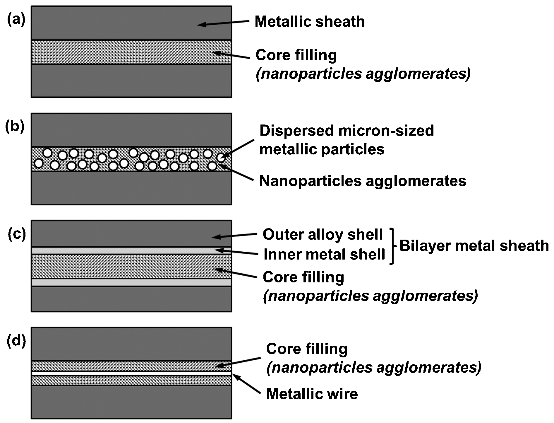
Schematics of various embodiments of nanocomposite cored wires: a cored wire with a metallic sheath around a core filling of nanoparticles agglomerates, b cored wire with a metallic sheath around a core filling of micrometre-sized metallic particles dispersed in nanoparticles agglomerates, c cored wire with bilayer metallic sheath around a core filling of nanoparticles agglomerates, and d cored wire with a metallic sheath around a core filling of nanoparticles agglomerates and a metallic wire extending through the core filling. Redrawn from Ref. 97
One variation of the nanocomposite wire incorporates micrometre-sized metal particles into the agglomerates of nanoparticles; Fig. 12b . The metal particles will melt with the metal sheath during spraying and act as a binder for the nanocomposite agglomerates. A second, inner layer of metal sheath can also be introduced into the cored wire, Fig. 12c , to serve as a high content alloying element and produce exothermal heat to improve particle flattening. A metal wire that extends through the core filling, Fig. 12d , can serve as an alloying element and improve the agglomerate uniformity during spraying. The incorporation of a metal wire also minimises the amount of oxidised inclusions in coatings.
The suppliers of nano-cored wires for thermal spray applications include Praxair Surface Technologies Inc. (Indianapolis, IN, USA), Inframat Corp. (Manchester, CT, USA), and the NanoSteel Company Inc. (Providence, RI, USA). Inframat Corp. has introduced a range of nanocomposite cored wires known as NanoCore, which includes core fillings such as WC–Co/Inconel 625, WC–Co/NiCr, WC–Co/Stainless steel. The nanocomposite cored wires by Praxair Surface Technologies Inc. (140MXC) and the NanoSteel Company Inc. (SHS 7570, SHS 8000, SHS 9172) are iron-based amorphous alloys that form nanocomposite coatings upon spraying. The compositions of these cored wires are specified in Table 4.
The compositions of several commercial nano-cored wires
Suspensions and solutions
Liquid feedstocks for thermal spray in the form of suspensions and solution precursors have been pioneered by Gitzhofer et al., 98 Tikkanen et al., 99,100 and Karthikeyen et al., 101,102 in the mid-1990s. Suspensions (slurries or sols) are fine solid particles that are dispersed within a liquid medium, where the fine particles are produced through mechanical, chemical, and/or thermal routes, as discussed in the ‘Agglomerated powder’ section. ‘Solution precursor’ refers to a mixture of constituent chemicals (e.g. inorganic salts or organometallics) dissolved in a solvent, which will react to form the desired material by high temperature reactions and processes in the thermal spray flame or jet. Tables 5 and 6 summarise the formulations of suspension and solution precursor feedstocks, respectively, for thermal spraying of known nanocomposite coatings.
Formulation of suspension feedstock for thermal spraying various nanocomposite coatings
HA: hydroxyapatite.
Formulation of solution precursor feedstock for thermal spraying of various nanocomposite coatings
HA: hydroxyapatite.
In suspension and SPTS, the feedstock carrier that is conventionally a gas is replaced by a liquid carrier. As such, there are distinctive factors that need to be considered: (i) particle dispersion and stability, (ii) solvent interaction with the flame or jet, (iii) solid loading, (iv) deposition efficiency, (v) precursor concentration, (vi) heat fluxes, and (vii) heat and momentum transfer. This section reviews the fundamental aspects of suspension and solution precursor feedstock preparation from items (i) to (v). More detailed information on the preparation of liquid feedstock and aspects (vi) and (vii) can be found in the review articles by Pawlowski 103,104 and Fauchais et al. 75,105
The dispersion and stability of the particles in a suspension feedstock are crucial to achieve homogeneous coatings. Fine particles tend to agglomerate because of their high surface energy even when they are mechanically agitated. Thus, electrostatic, steric, or electrosteric dispersants are used to disperse and stabilise nanoparticle suspensions by establishing long-range repulsive forces. Electrostatic stabilisation is achieved through acquisition of surface charges, or an electric double layer, through mechanisms such as adsorption, dissociation, ionisation, and/or surface reaction when immersed in an aqueous solution; 106,107 Fig. 13a . On the other hand, steric stabilisation is induced by adsorption or grafting of polymers, or macromolecules onto surfaces; 106,107 Fig. 13b . The combination of electrostatic and steric effects is known as electrosteric stabilisation and is typically achieved through adsorption of charged polyelectrolytes; Fig. 13c .
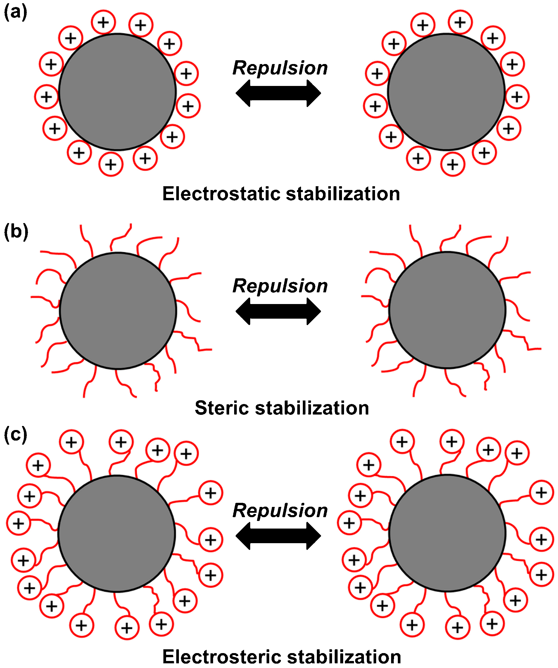
Schematics representation of particles interaction with a electrostatic stabilisation, b steric stabilisation, and c electrosteric stabilisation
Most dispersants used to prepare thermal spray suspensions are electrosteric. For instance, cationic polyethyleneimine 108 and anionic ammonium polyacrylate 109 polyelectrolytes were used as dispersants for Al2O3–YSZ suspensions; Table 5. The stability of particle dispersion is determined by the zeta potential, which is the potential between the charged surface and the electrolyte solution. 106 A zeta potential of at least ±30 mV is required to achieve a stable suspension. 110,111 Therefore, stability of a suspension depends on the type of dispersant and pH value of the suspension. In suspension systems where both acid and base components are present, such as in WC–Co where WO3 is a Lewis acid while CoO is a base, achieving stability becomes an intricate process of achieving the equilibrium point between activation of the dispersant and dissolution of WO3 or CoO. 112,113
Additional measures to improve particle dispersion, such as milling and sonication, have also been implemented for nanocomposite suspension feedstocks; Table 5. Plasticisers such as polyvinyl alcohol and polyethylene glycol were added to increase suspension viscosity, which will inherently improve the suspension stability. However, it should be noted that the suspension viscosity should be adjusted by the solid loading and amount of dispersant and plasticisers so that it exhibits a minimum value with sufficient stability and shear-thinning behaviour to facilitate suspension feeding. 75,104
Selection of the solvent in the suspension and solution precursor feedstock, which is typically water, alcohol, or a combination of both, dictates the interaction of the suspension and precursor molecules with the thermal spray flame or jet. Water has a cooling effect while alcohol heats up the flame or jet, because of their different enthalpies of vaporisation; e.g. enthalpy of vaporisation for water and ethanol are 2·26 and 0·84 kJ g−1, respectively. Alcohol also needs a greater injection velocity than water to penetrate the flame or jet because of its lower density; 103 i.e. densities of ethanol and water are 0·79 and 1·0 g cm−3, respectively. The heat required to vaporise water is three times that of ethanol 114 while the deposition efficiency of an ethanol-based YSZ suspension is double that of a water-based YSZ suspension. 115
Solid loading is the relative amount of solid particles in a suspension or solution precursor feedstock. Generally, the solid loading of nanocomposite suspensions reported in the literature does not exceed 50 wt-%; Table 5. Typically, the solid loading does not exceed 25 wt-%, except in the case of a sol, because the degree of particle melting decreases with increasing solid loading. 75,104 Solid loading also influences the particle velocity through its effect on feedstock viscosity; i.e. viscosity increases with increased solid loading. Therefore, solid loading has an important role in the deposition efficiency of the process, where deposition efficiency increases when the particle melting and particle velocity increase. However, it should be kept in mind that particle melting reduces the degree of nanostructure morphology. The deposition efficiency of suspension thermal spray (STS) is about one fourth to one-third of that of conventional coatings; 75 i.e. a deposition efficiency of 20% is typical for this type of materials processing, which can be compared to values of 55–80% for conventional thermal spray techniques.
Solution precursor feedstocks are prepared by mixing stoichiometric amounts of inorganic salts or organometallic precursors with water and/or alcohol; Table 6. Important aspects to be considered in the selection of precursor materials are the (i) precursor costs, (ii) product formation and crystallisation temperature, (iii) stability of the precursors, and (iv) potential harmful by-products. Solvents that have low surface tension and low boiling point are recommended to produce dense coatings; e.g. ethanol compared to triethanolamine, as these solvents dissociate and evaporate more easily, which is more likely to lead to full pyrolysis. 116
Unlike suspension feedstock, the solid phase contents of solution feedstocks are often reported in the form of precursor concentration. The resulting solid phase content can be calculated using the volume, concentration, and molecular masses of the respective precursor compounds in the feedstock. A high precursor concentration that is close to the equilibrium saturation concentration is recommended to induce volumetric precipitation for dense coatings. 117 The equilibrium saturation concentration is the concentration at which the rate of dissolution and precipitation of the solid and solution phases, respectively, becomes equivalent. Although the increase of precursor concentration increases the solution viscosity, it has little effect on the surface tension and specific mass, hence the pyrolysis behaviour and crystallisation temperature remain unaffected. 117
Thermal spray deposition: process and microstructure
The thermal spray deposition techniques for nanostructured coatings can be classified into three categories: (i) conventional approaches, i.e. flame, plasma, high velocity oxygen fuel (HVOF) and wire arc spray of agglomerated powder feedstock; (ii) cold spray of agglomerated powder feedstock; and (iii) suspension and solution precursor thermal spray of liquid feedstock. Each of these techniques produces coatings through different mechanisms; thereby retaining the nanostructure of the feedstock to different extents that are reflected in their distinctive coating microstructures. The deposition of nanocomposite coatings herein will be discussed from the viewpoint of coatings deposited from nanostructured starting material. Coatings that exhibit (i) a nano-width columnar structure in individual splats, or (ii) coatings that acquired nanocrystalline phases after post-deposition treatment are considered out-of-scope for the current discussion.
Conventional approaches
Formation mechanisms
Thermal sprayed nanostructured coatings via conventional approaches; i.e. deposition of powder feedstock using thermal spray processes other than cold spray, have mostly been deposited using micrometre-sized agglomerates of nanoparticles. Such an approach can be considered as a combination of top-down and bottom-up approaches of producing nanostructured materials because the feedstock are often crushed to nanometre-sized from micrometre-sized particles (top-down), then agglomerated to micrometre-sized and deposited to build-up nanostructured coatings with a thickness in the micrometre range (bottom-up).
Upon entering the thermal spray source, particle melting initiates from the surface of the particle. As agglomerated particles are porous and have low apparent density, the thermal transport properties of these particles are different than those of the conventional, dense feedstock particles. The heat flux from the thermal spray source is retarded by the pores and heat diffusion is lower compared to dense particles of the same diameter. 118 This effect allows partial melting of the particles for effective deposition while retaining the nanostructural characteristics of the feedstock. As such, the particle momentum has to be adjusted by fine-tuning the spray parameters to allow for an appropriate degree of particle melting during in-flight. Large feedstock particles are favoured when sprayed through this route to avoid a high degree of melting. 119 It is stressed that the thermal spray parameters that are employed for conventional feedstocks cannot be used for feedstock of nano-character because any nano-features would be lost during the process.
It should be emphasised that partial melting of feedstock is prevalent in all thermal spray processes and it is not uncommon to ascertain ‘unmelts’ or ‘partial melts’ within a thermal spray microstructure. However, for the thermal spray of nanocomposites, partial and incomplete melting is a preferred mechanism of coating formation because this allows retention of the nanostructure within the feedstock.
Upon impact on the substrate, the molten fraction of the particles solidifies to micrometre-sized artefacts that enhance the coating's bond strength; while the non-molten nanoparticles retain the nanostructure character of the deposit. Therefore, partial melting of the particles causes the loss of nanostructural characteristics to some extent. Nanocomposite coatings sprayed through this approach will not be completely nanostructured, but instead have a bimodal structure, 75,120 where the nano-sized grains are embedded within micrometre-sized grains. A loss of nanostructure within the molten phase is also contributed by the sintering of the liquid phase, because the sintering time is reduced to the order of nanoseconds compared to solid phase sintering that may take hours. 118 Porosity in the feedstock is introduced into the coatings as porous nanozones when the molten region does not fully infiltrate into the non-molten core of the partially molten particles, which generates improved properties for applications such as thermal barrier coatings and abradable seals. The formation of a bimodal structure through (i) partial melting, and (ii) deposition of agglomerated nanocomposite particles is shown schematically in Fig. 14.
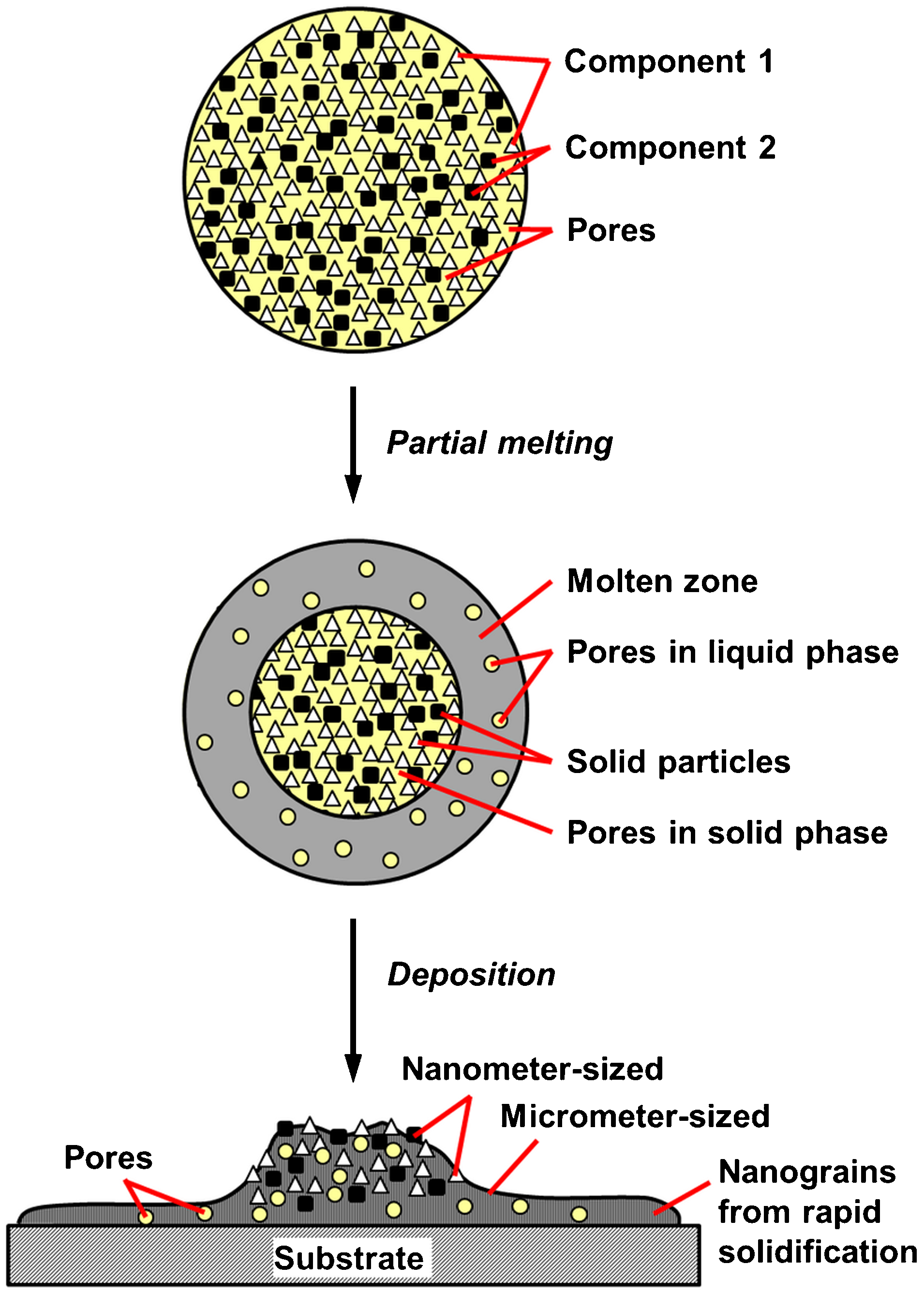
Schematic representation of agglomerated nanostructured particle melting and deposition by conventional thermal spray processes (Δ: component 1; ▄: component 2; ○: pore)
Bimodal nano- and microstructure
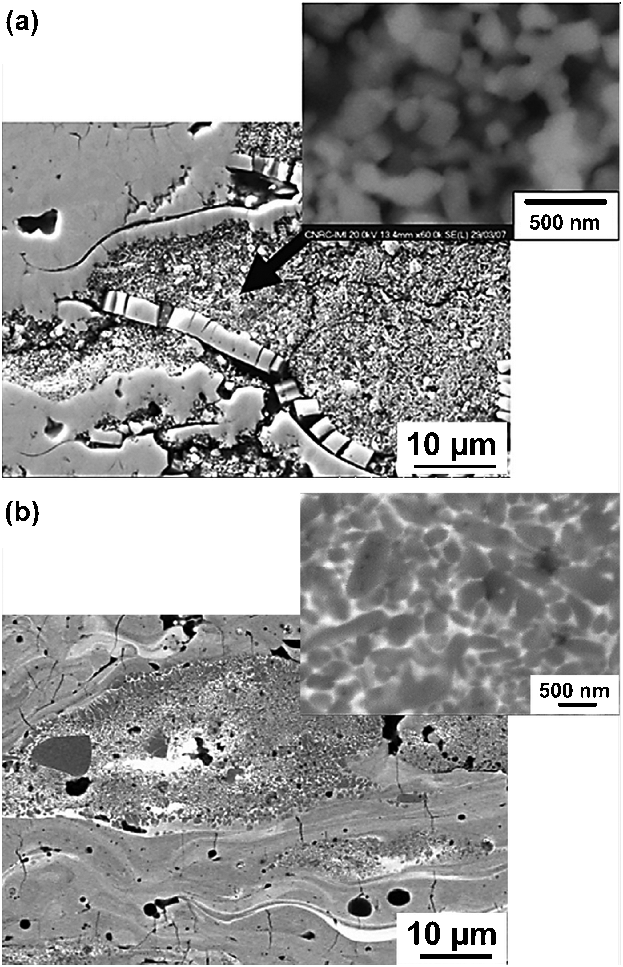
The microstructure of plasma or HVOF sprayed nanocomposite coatings, as viewed at magnifications of less than 2 000×, resembles the lamellae of conventional thermal spray coatings. However, magnifications greater than 2 000× reveal the nanostructural characteristics of the coatings that are retained through partially or non-molten particles; thus, contributing to the bimodal structured coatings discussed in the previous section; Fig. 15. An example of microstructural comparison between conventional and nanostructured composite coatings is depicted in Fig. 16. The lamellar structure is detected in the molten region of the coatings (marked as ‘A’) while the partially molten regions exhibit embedded particulates (marked as ‘B’ and ‘C’). The extent of the nanostructure in such coatings is determined by the amount of partially or non-molten particles retained in the coatings.
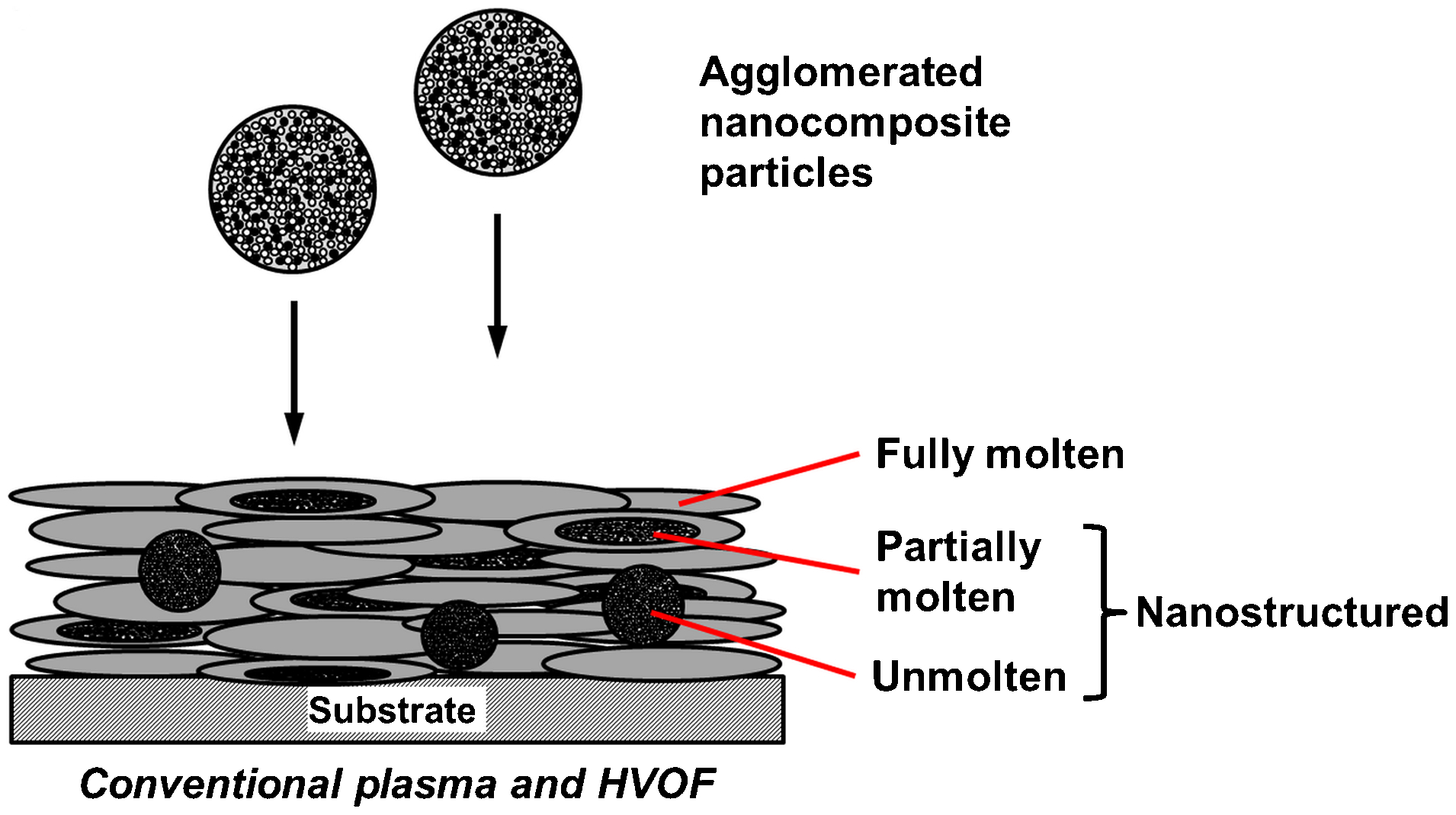
Schematic of nanocomposite coatings microstructure deposited by conventional thermal spray processes using agglomerated powder feedstock
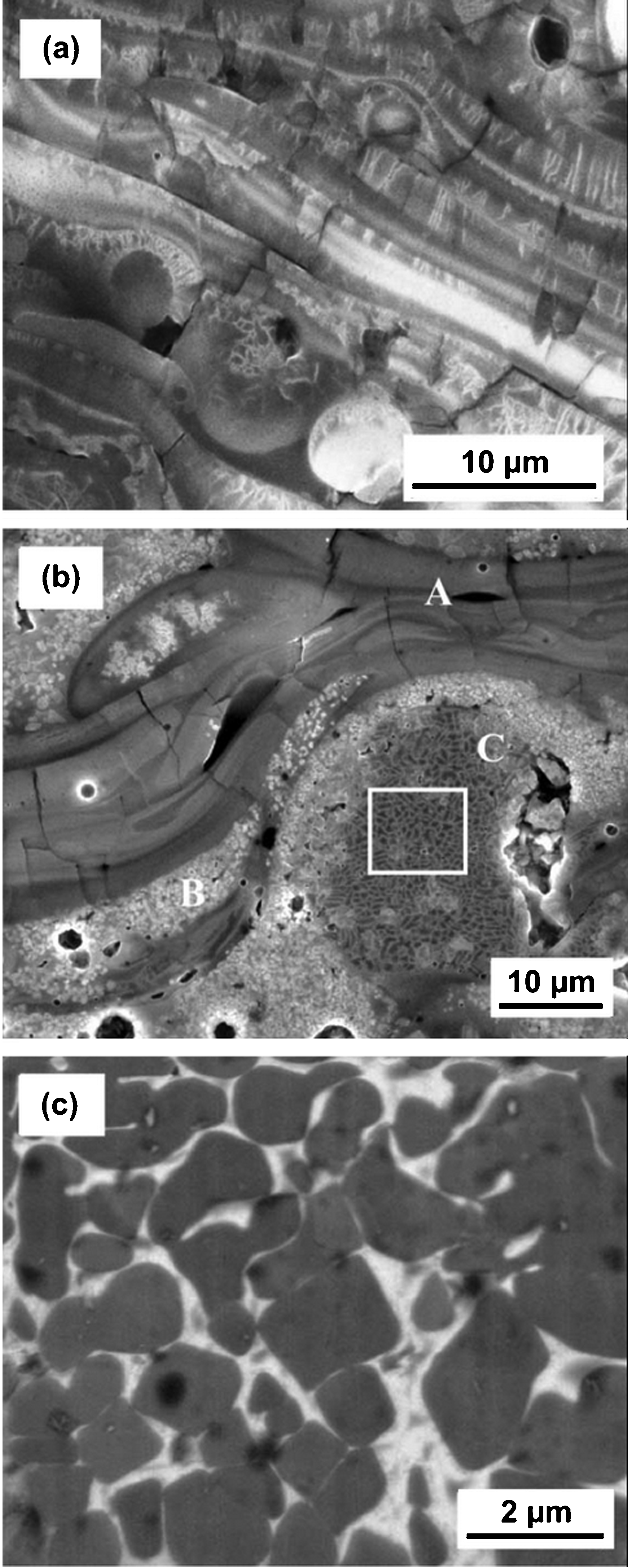
Cross-sections of plasma sprayed Al2O3–13wt-%TiO2 coatings: a Conventional coatings showing columnar grain boundaries, b nanostructured coatings consisting particulates embedded in partially molten regions, and c high magnification of the region highlighted in b. Reproduced from Goberman et al. 125 with permission from Elsevier
Plasma sprayed ZrO2–Y2O3 and Al2O3–TiO2 coatings have exhibited up to 52 and 25% of nanoparticles retainment via the non-molten phase, respectively. 120,121 Molten splats may consist of strongly bound nano-sized crystallites created during the rapid solidification process. 122 Such molten splats have a nano-width columnar structure. It should be noted that a high percentage of nanozones does not necessarily indicate superior performance. There is consensus that a range of nanostructure content is necessary to achieve optimal coating properties; above and below which the specified properties will deteriorate. 79 For instance, plasma sprayed Al2O3–8wt-%TiO2 coatings exhibit optimal wear properties at 25% retainment of nanostructure 123–125 while Al2O3–13wt-%TiO2 coatings perform optimally at 15–20% of nanostructure retainment. 121
An important microstructural aspect of nanostructured coatings deposited through the conventional approaches is the density of the nanozones. The density of the coatings determines their prospective applications; e.g. porous ZrO2–7wt-%Y2O3 coatings for thermal barrier applications and dense Al2O3–13wt-%TiO2 coatings for wear resistant coatings; Fig. 17. Coatings with specific nanozone density can be engineered through optimisation of particle temperature, velocity, and size distribution. The porous nature of the agglomerated feedstock is preserved in coatings when molten portions of the particle do not penetrate into the porous regions during in-flight, impact, and solidification; whereas a dense structure is achieved by enabling such infiltration.
Therefore, porous nanozones are produced by using large agglomerates and achieving a surface temperature that is around the melting point of the material, while dense nanozones are obtained by attaining a surface temperature that is significantly higher than the melting point of the material. 75 For instance, 35% porous nanozones were embedded in ZrO2–7wt-%Y2O3 coatings sprayed at an average particle temperature and velocity of 2 670°C and 210 m s−1, respectively. 119 High velocity oxygen fuel is a more effective process compared to plasma spray to produce dense nanostructured coatings because of its high particle velocity. However, the lower particle temperature and shorter in-flight time must be compensated by using smaller particles with a narrow size distribution to provide a high degree of melting so that the agglomerate porosity can be infiltrated.
Materials overview
Throughout the literature, the integrity of nanocomposite coating deposition via conventional routes was accomplished through HVOF or plasma spray processes. There were also reports on nanocomposite coatings processed by flame spray, wire arc spray, and detonation spray, although these works were relatively scarce. Generally, flame spray and HVOF were used to deposit materials sensitive to high temperature such as cermets or polymer-matrix nanocomposites while plasma spray was used for deposition of ceramic nanocomposites. Examples of nanocomposite coatings deposited by flame spray, HVOF, and plasma spray are presented in Tables 7– Table 8 9, respectively.
Published work on nanocomposite coatings deposited by flame spraying of powder feedstock
MWCNT: multi-walled carbon nanotube; SS: stainless steel.
Published work on nanocomposite coatings deposited by high velocity oxygen fuel (HVOF) spraying of powder feedstock
HA: hydroxyapatite; MWCNT: multi-walled carbon nanotube; ND: nanodiamond.
Published work on nanocomposite coatings deposited by plasma spraying of powder feedstock
HA: hydroxyapatite; MWCNT: multi-walled carbon nanotube.
Cold spray
Formation mechanisms
Despite the fact that nanocomposite coatings deposited by cold spray used similar feedstock as the conventional approaches, the coatings exhibited different microstructures and properties because of the differing deposition mechanisms between cold spray and other thermal spray processes. That is, cold spray operates at a much lower temperature compared to other thermal spray processes. For example, cold spray operates at a maximum of 800°C but typically 400°C, which can be compared to >2 500°C for a plasma spray process. 52,126 Therefore, deposition via cold spray is based on particle deformation rather than the melting of particles that is experienced for conventional thermal spray processes. The particle velocity must exceed a certain critical velocity that is unique to the material for effective deposition to occur. 127,128 Particles impacting at velocity below the critical velocity will erode the substrate material without effective deposition. A deformable phase, which is typically a ductile metal phase, is required for deposition of brittle or hard materials such as ceramics so that a composite coating may evolve.
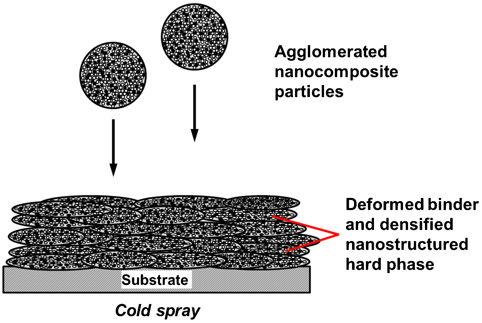
Upon impact with sufficient energy, the cold spray particles undergo high plastic strain rates that result in adiabatic heating of the contact zone surroundings and the material exhibits localised softening. However, the heat from adiabatic shear instabilities is typically insufficient to cause particle melting. Because the particles are deposited without undergoing melting, the nanostructure of the original feedstock is preserved in the coatings. Grain coarsening that typically occurs during droplet formation in the liquid state in conventional approaches is also prevented during the cold spray deposition process. More information on the gas dynamics, deposition mechanisms, and influence of spray parameters by the cold spray method can be found in Refs. 52, 126, and 129. Figure 18 illustrates the formation of nanocomposite coatings via the cold spray route.
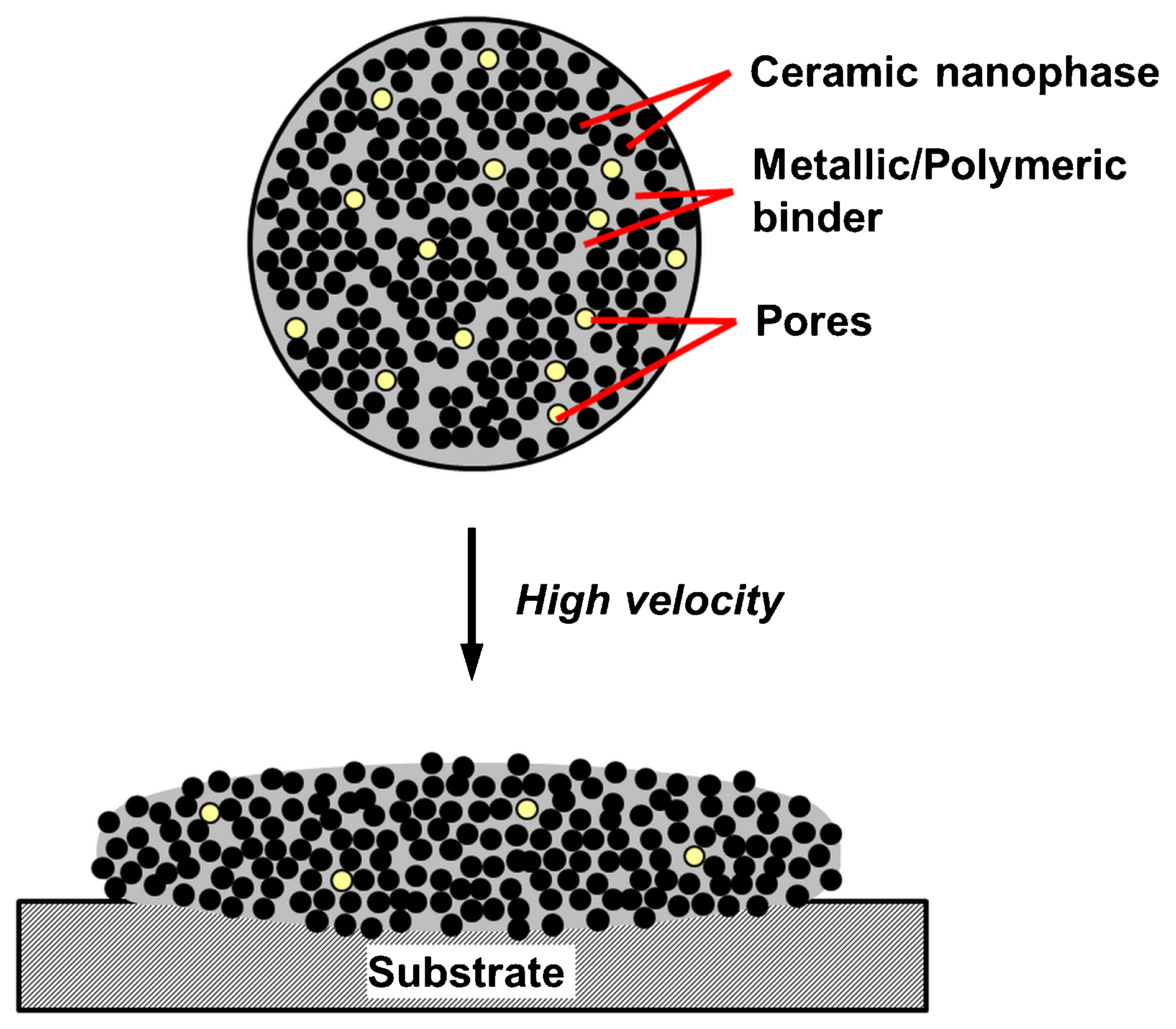
Schematic representation of nanocomposite deposition via the cold spray process
Coating microstructures
Generally, the nanocomposite coatings deposited by cold spraying agglomerated particles exhibit a dense and crack-free microstructure, with a uniform distribution of particulates among the binder phase; Fig. 19. The lamellar structure that is typical of thermal spray coatings is not distinguishable. 130–132 The dense coating microstructure compared to the porous agglomerated feedstock is attributed to effective deposition and densification through particle deformation at high impact velocity. The supersonic impact velocity also caused the formation of irregular substrate surfaces with valley and re-entrant features that are effectively filled by the incoming particles. 133 The low porosity, absence of cracks, indistinguishable particle interfaces, and absence of spallation and delamination indicated that the coatings demonstrated good cohesion and adhesion. 131,134
Schematic of nanocomposite coatings microstructure deposited by cold spray processes using agglomerated powder feedstock
As cold spray operates at a much lower temperature compared to the conventional approaches, there was no evidence of particle melting in the coatings and the nanostructure of the feedstock is retained in the coatings. Figure 20 depicts an example of a cold sprayed nanocomposite coating cross-section, and the view of the retained nanostructure at higher magnification. Cold sprayed nanocomposite coatings are more dense and hard compared to their micrometre-structured counterparts because higher particle velocity can be achieved for smaller particles using the same gas flowrate. 135 In addition, there is a tendency for the ductile matrix phase to undergo strain hardening during the cold spray process. 136
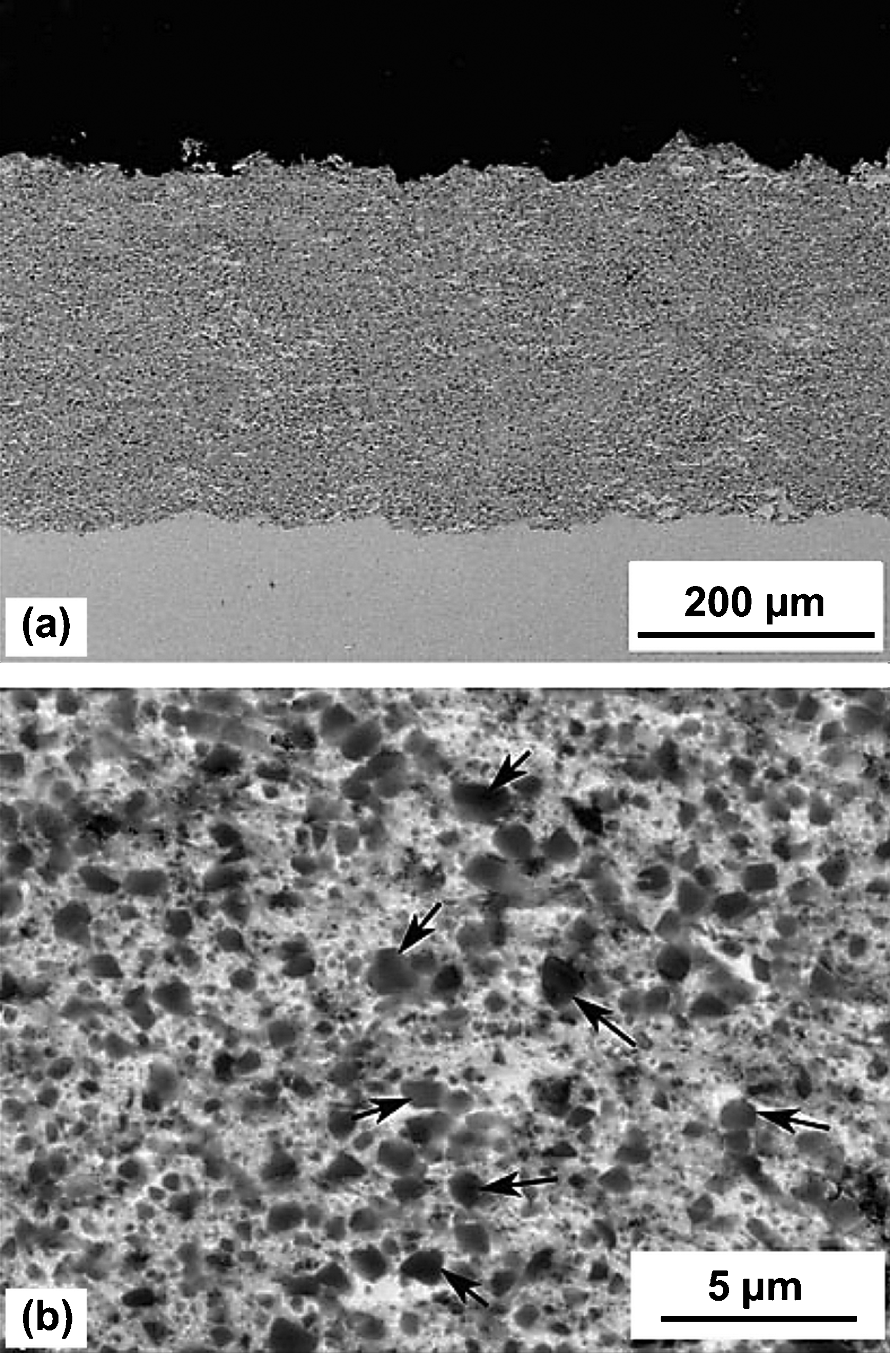
Cross-sections of cold sprayed NiCrAl–40vol.-%BN nanocomposite coatings. The arrows indicate cubic boron nitride dispersoids. Reproduced from Luo and Li 132 with permission from Springer Science and Business Media
Building up of composites with micrometer-sized hard ceramic particles such as oxides or carbides by cold spray has been difficult compared to plasma and HVOF deposition because of poor deposition efficiency. However, cold sprayed coatings are favoured over conventional methods because the materials do not undergo high temperature phase transitions into undesirable phases. The use of nanostructured feedstock significantly improves the deposition efficiency and density of cold sprayed coatings of such materials; e.g. tungsten carbide–cobalt, WC–Co. 137 Such an outcome is explained by the fact that the critical velocity is lowered and there was a higher surface area for contact between the binder phase and hard ceramic particles for effective deposition of nanostructured particles. Cold spraying of conventional feedstock using similar processing parameters result in erosion and/or grain refinement rather than deposition because of insufficient contact between the hard phase and binder.
Despite the fact that the deformation mechanisms of cold spray deposition is advantageous in producing dense coatings, the extent of particle deformation becomes a precarious matter when the preservation of the initial particle structure is critical to maintain effective functional properties of the coatings; e.g. CNTs composites. Similar to other cold sprayed coatings, the nanocomposite coatings incorporating CNTs underwent significant grain refinement associated with the high strain rate plastic deformation of the process. 138,139 Although the CNTs were retained and distributed uniformly in the coatings, there was evidence of structural damage through shortening of CNTs by ∼30%. 138 Fractured CNT tips were also evident as a result of impact and/or shear by incoming particles. However, the relative degree of structural damage, measured by the ratio of D- to G-band intensity (I D/I G) in Raman spectroscopy, indicated that the majority of the CNT structural damage occurred during the milling process of feedstock preparation rather than at the deposition stage. 139 The extent of structural damage can be reduced by cold spraying under low pressure (0·5–0·6 MPa) conditions. 139
Materials overview
Cold spray has mostly been used to deposit nanocomposite coatings with nano-sized ceramic particulates encapsulated by a metallic or polymeric binder. Table 10 summarises the compositions and feedstock preparation methods for cold sprayed nanocomposite coatings reported in the literature.
Published work on nanocomposite coatings deposited by cold spraying of powder feedstock
HA: hydroxyapatite; MWCNT: multi-walled carbon nanotube; PEG: polyethylene glycol; PEEK: polyether ether ketone.
Suspension and solution precursor thermal spray
Formation mechanisms
The development of STS and SPTS has rendered thermal spray processes more versatile in the deposition of nanocomposite coatings. (Note: within the literature the acronyms of ‘SPS’ and ‘SPPS’ are prevalent, where the substitution of ‘T’ is replaced by ‘P’ for ‘plasma’. It is considered within the current review that the more generic ‘thermal’ term is appropriate because this encompasses a wider range of process adaptions.) These techniques are able to fabricate nanostructured coatings without the need for costly and time consuming preparation of nanostructured free flowing particles. In addition, STS and SPTS are valuable in depositing composites with immiscible components and thin coatings within the nano- and sub-micron range. The STS method was developed based on the requisite that a denser carrier is needed for the injection and transport of nanoparticles in high enthalpy flow, while the SPTS technique can be considered as a hybrid of chemical and physical methods in producing nanoparticles discussed in the ‘Agglomerated powder’ section. Therefore, the SPTS process can be used to produce nanocomposite coatings with metastable phases. 140 The thermal spray sources that are typically used for STS are plasma spray and HVOF, although the former is more favoured than the latter, while SPTS typically employs plasma spray.
The STS and SPTS techniques have feeding systems and spray conditions that are distinctive from the conventional powder feeding systems: 75 (i) the feedstock carrier is a liquid rather than a gas, (ii) the spray distance is shorter, approximately one-half to one fifth (i.e., 3–7 cm), than in conventional approaches because nanoparticles have low inertia, and (iii) the deposition efficiency is about one fourth to one-third, of that of the conventional approaches, i.e. the DE is typically 15–20% for the STS and SPTS techniques. The feedstock can be injected as a liquid jet or as droplets through atomisation. In mechanical injection, the liquid feedstock is either forced through the nozzle from a pressurised reservoir or through superimposing pressure pulses at variable frequencies using a magnetostrictive rod. 105 The liquid jet starts to break up on exiting the nozzle because of air resistance. Atomisation uses external forces such as external pressure, acoustic energy, and centrifugal forces, to break up the bulk liquid before directing the atomised particle stream into the thermal spray effluent.
Upon entering the high velocity flame or plasma jet, the suspension droplets may undergo secondary fragmentation or aerodynamic break up into smaller droplets because of shear deformation from the drag force of the droplets. The extent of the aerodynamic break up depends on the Weber number of the droplets relative to the flame or plasma. 141 The solvent encapsulating the nanoparticles is vaporised to form nano- or sub-micron sized aggregates. The aggregates undergo solid phase sintering, where the duration of sintering depends on the flame or jet temperature. Depending on the spray conditions, some of the finer particles are vaporised while others undergo melting and are deposited on impact with the substrate. More details concerning the heat and mass transfer for the STS process can be found in Refs. 75, 104, and 105. The schematics of coating formation mechanisms by STS are depicted in Fig. 21.
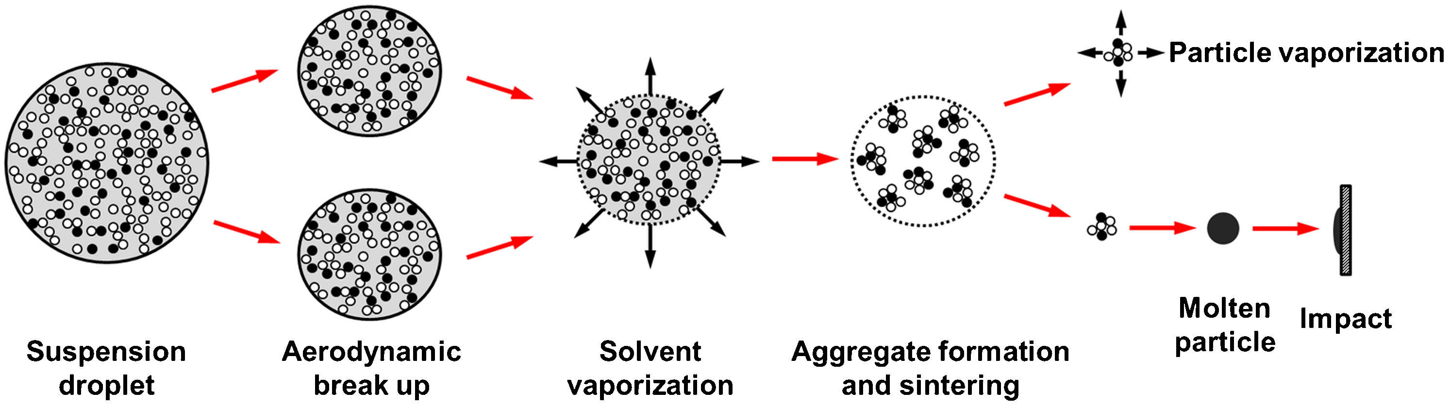
Schematics of nanocomposite coating formation mechanisms in suspension thermal spray (STS)
In SPTS, the liquid precursor droplets undergo similar aerodynamic break up as in STS on entering the thermal spray stream to form smaller droplets. The aerodynamic break up occurs in the order of microseconds. 142 The droplets are then subjected to heating and solvent vaporisation, followed by solid phase condensation. The chemical reaction between the precursors is initiated, and the reaction progresses through nucleation and growth until at least one of the precursors is fully consumed. The coating formation mechanisms by SPTS are illustrated in Fig. 22. Depending on the heating rate and nature of the precipitation during heating and vaporisation, different morphologies of dense particles and/or solid shells may be obtained. 143 Dense particles are typically formed within small droplets with high solute diffusivity when the solute concentration and precipitation occurs uniformly throughout the droplets, followed by pyrolysis and sintering; Fig. 22a . Some of the particles may interact to form agglomerates and/or large particles. 101
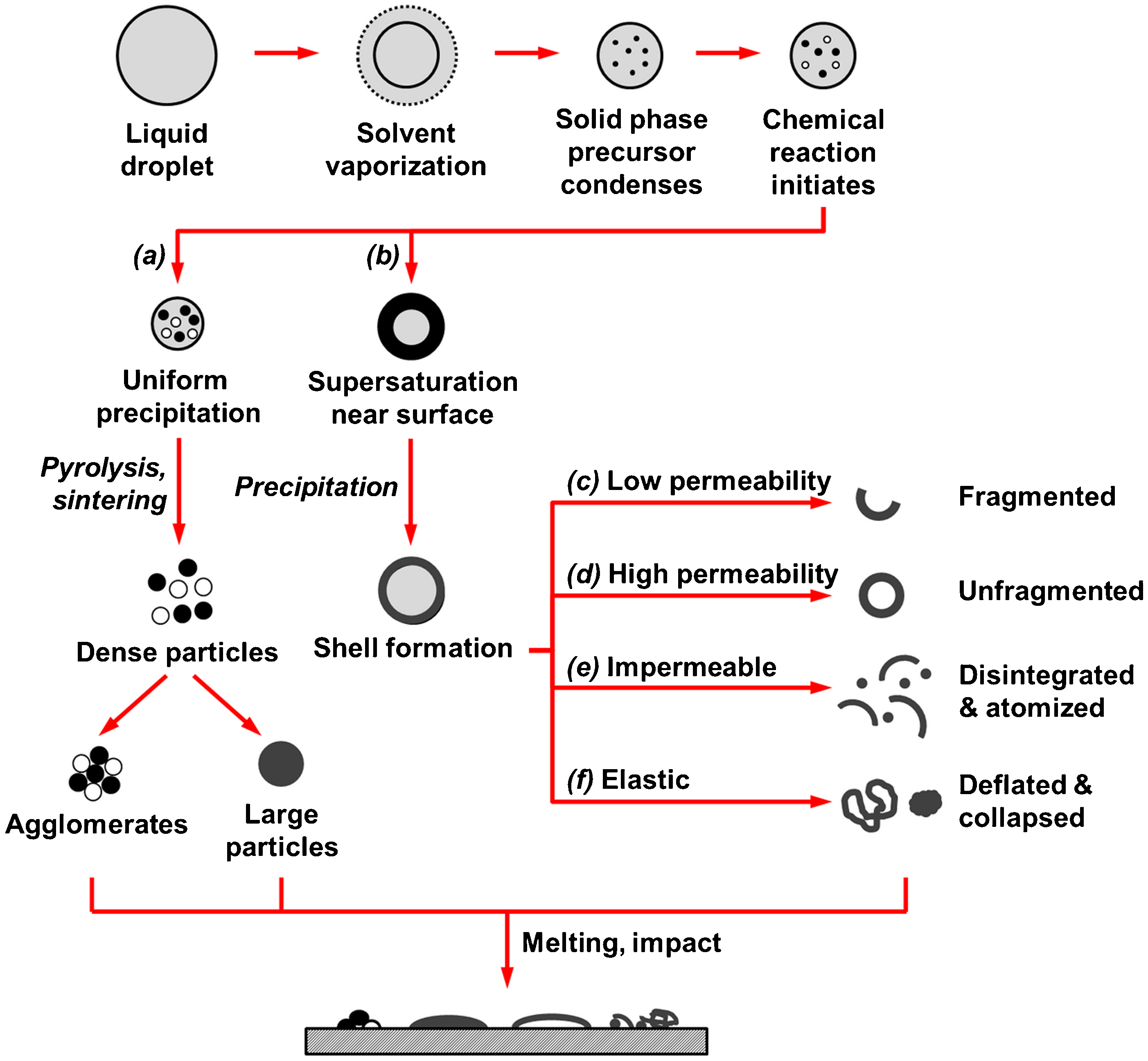
Schematics of nanocomposite coating formation mechanisms in solution precursor thermal spray (SPTS)
Supersaturation occurs near the droplet surface when the rate of solvent vaporisation exceeds the rate of solute diffusion such that a high solute concentration builds up near the surface; Fig. 22b . At a critical solute concentration, a porous shell surrounding a liquid core is formed through precipitation. Depending on the permeability of the shells, different routes of internal vaporisation and pressurisation lead to a variation of shell formations. For a low permeability shell, the internal pressurisation internal pressurisation, arising from liquid core vaporisation, leads to shell fracture and the formation of fragmented shells; Fig. 22c . A high permeability shell enables sufficient release of the internal pressure to form an unfragmented, hollow shell; Fig. 22d . Internal pressurisation within an impermeable shell results in shell rupture and secondary atomisation of the liquid core to form disintegrated shells and fine particles; Fig. 22e . Some precursors may form an elastic shell that undergoes inflation from internal vaporisation and pressurisation, which is then followed by deflation and collapse into a precipitate clump; Fig. 22f .
The outcome of these proposed mechanisms is the evolution of particles that exhibit morphologies that then participate in the classical thermal spray deposition process. The dense particles and various shells are melted and deposited on impact with the substrate. The particle morphology depends on the (i) droplet size, (ii) precursors and solute chemistry, (iii) solute diffusivity and solubility, and (iv) droplet thermal history. 143 Generally, large droplets and high heating rates result in hollow particles, while small droplets and low heating rates evolve dense particles. 143 Further details on the solution — hot gas interaction and numerical aspects of droplet fragmentation, heat exchange, vaporisation rates and internal pressurisation are available in Refs. 75, 104, 105, and 142.
Microstructure: suspension thermal sprayed coatings
Depending on the feedstock characteristics and processing parameters, the microstructure of STS nanocomposite coatings can take the form of a granular nanostructure, ultrafine lamellar structure or a combination of both; Fig. 23. For instance, the microstructure of a Y2O3–50vol.-%MgO nanocomposite coating consists of a lamellar structure with entrapped unmelts in three distinct arrangements: (i) a prominent lamellar structure comprising Y2O3 (30–140 nm) and MgO (5–30 nm) phases arranged in alternating wavy streaks, (ii) a dispersion of relatively small MgO (30–140 nm) grains in a continuous Y2O3 matrix, which resembles precipitation from a supersaturated solid solution, and (iii) unmelted and/or resolidified particles entrapped within lamellae. 144
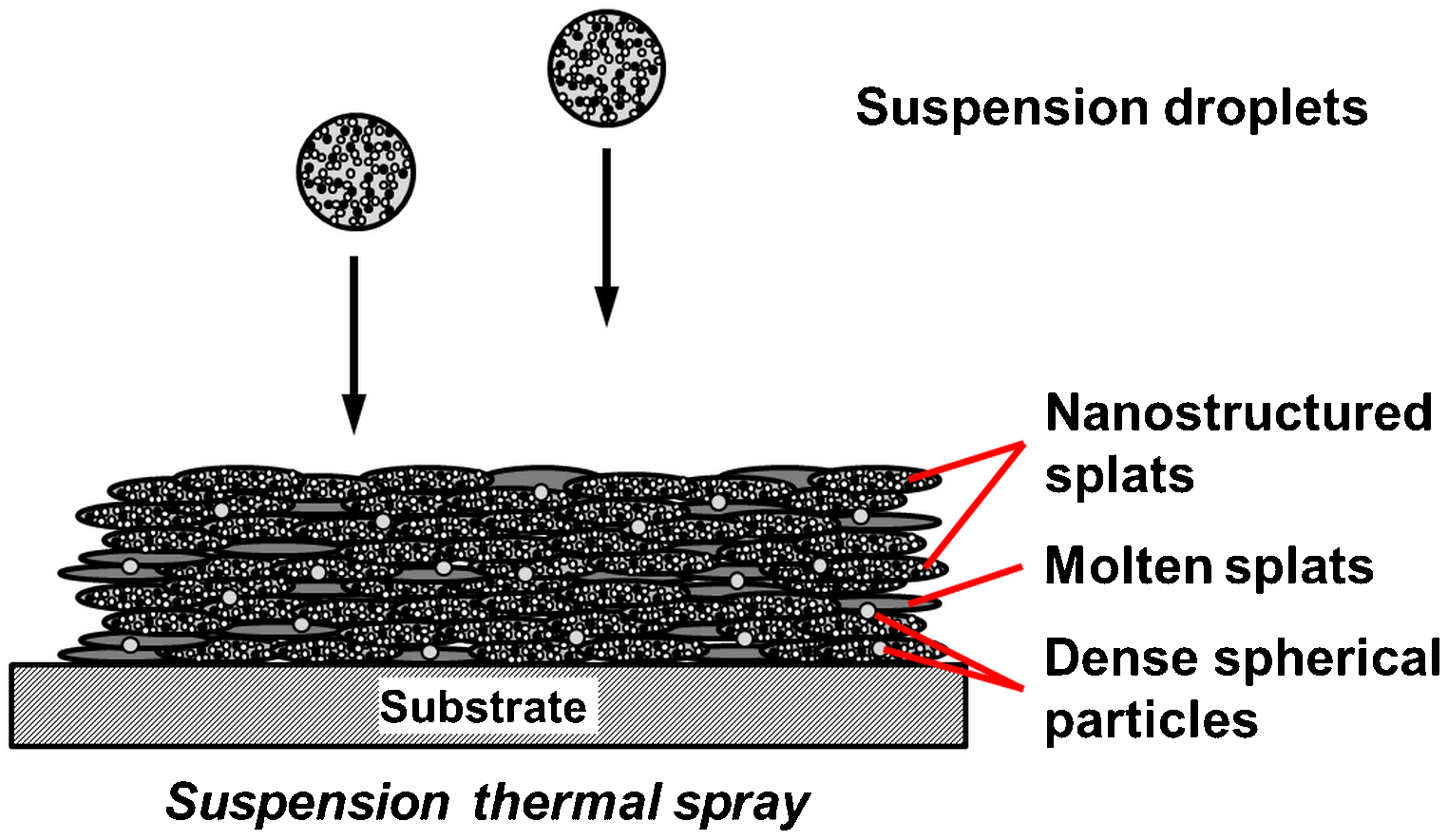
Schematic of nanocomposite coatings microstructure deposited by suspension thermal spray (STS) process
A granular structure, similar to those of sintered bulk materials, is developed when (i) non-molten or resolidified particles impact with momentum sufficient for deposition, or (ii) non-molten nanoparticulates of one phase are embedded or entrapped within the molten matrix of another phase. For example, the processing parameters to deposit an Al2O3–ZrO2 coating were optimised so that all the Al2O3 particles were molten to form a matrix that encapsulated the solid state ZrO2 nanoparticulates. 145 On the other hand, a lamellar structure arises from the deposition of molten particles at high impact velocity. However, the lamellar structure deposited by STS may be distinguished from that of conventional thermal spray coatings with respect to their splat size and degree of flattening. For instance, the ultrafine splats observed in suspension plasma sprayed Al2O3–ZrO2 coatings have similar morphology to that of conventional plasma sprayed coatings, but are smaller in diameter; i.e. 1–5 μm compared to 100–150 μm in conventional coatings. 146
The development of a STS coating microstructure is contingent on the aerodynamic fragmentation of suspension droplets and their penetration into the thermal spray jet or flame. A high degree of droplet fragmentation creates a large dispersion of particle trajectories, which will result in non-uniform particle melting; thereby forming porous coatings with poor cohesion. The extent of droplet fragmentation depends on the (i) characteristics of thermal spray source; e.g. DC vs. RF plasma; (ii) injection parameters; e.g. injection port diameter, injection angle, injection position, and feedrate; (iii) droplet size distribution; and (iv) surface tension of the solvent. 105,115,147 Further details on the droplet fragmentation and vaporisation mechanisms are available in Refs. 105 and 115. The deformation of suspension particles on impact can take various forms, such as disk-type or splash-type splats, large clusters, overspray, and recondensed particles; which all depend on the droplet degree of fragmentation, thermal history, and kinetic energy. The build-up of these individual deposits collectively determines the final microstructure of STS coatings. The prerequisite and formulations of suspension particles interpreted in relation to the balance of energy are discussed in detail in Ref. 104.
Similar to conventional thermal sprayed coatings, the microstructure of STS coatings is influenced substantially by process parameters that directly affect the particle temperature and velocity. 148 One such parameter that is unique to the STS process is the solid loading. The increase of solid loading effectively (i) increases the enthalpy required to melt the particle as well as (ii) decreases the particle velocity because of an increase in the suspension-to-droplet mass ratio. Therefore, any improvements in terms of particle penetration resulting from an increased solid loading are offset by the decrease of particle melting. 147 For example, an increase of solid loading of Al2O3–25wt-%ZrO2 suspension from 5 to 20wt-% produced a thicker, but more porous coating because of increased deposition efficiency and reduced splat flattening, respectively. 109 Non-optimised spray conditions resulted in large, micrometre-sized pores in STS nanocomposite coatings. 149 The increase of solid loading was also reported to increase the spacing of horizontal cracks; although there were no significant changes in the vertical crack density. 148
Another critical microstructural aspect of STS coatings is the inclusion of recondensed particles. Fine particles that were vaporised from the thermal spray jet tend to recondense downstream and deposit on to the substrate or coating surface. The adherence of such particles on the substrate or coating surface, in addition to the non-melted particles that travelled at the periphery of the jet, contribute to defects between two successive passes. Figure 24 shows an example of microstructural defects in a STS coating that has evolved from recondensed particles. Such phenomenon is especially severe for fine ceramic particles that experience high heat flux under STS conditions because they have the tendency to adhere to coating surfaces over 700–800°C. 105,150 The formation of such defects can be minimised by optimising the suspension mass load and spray conditions.
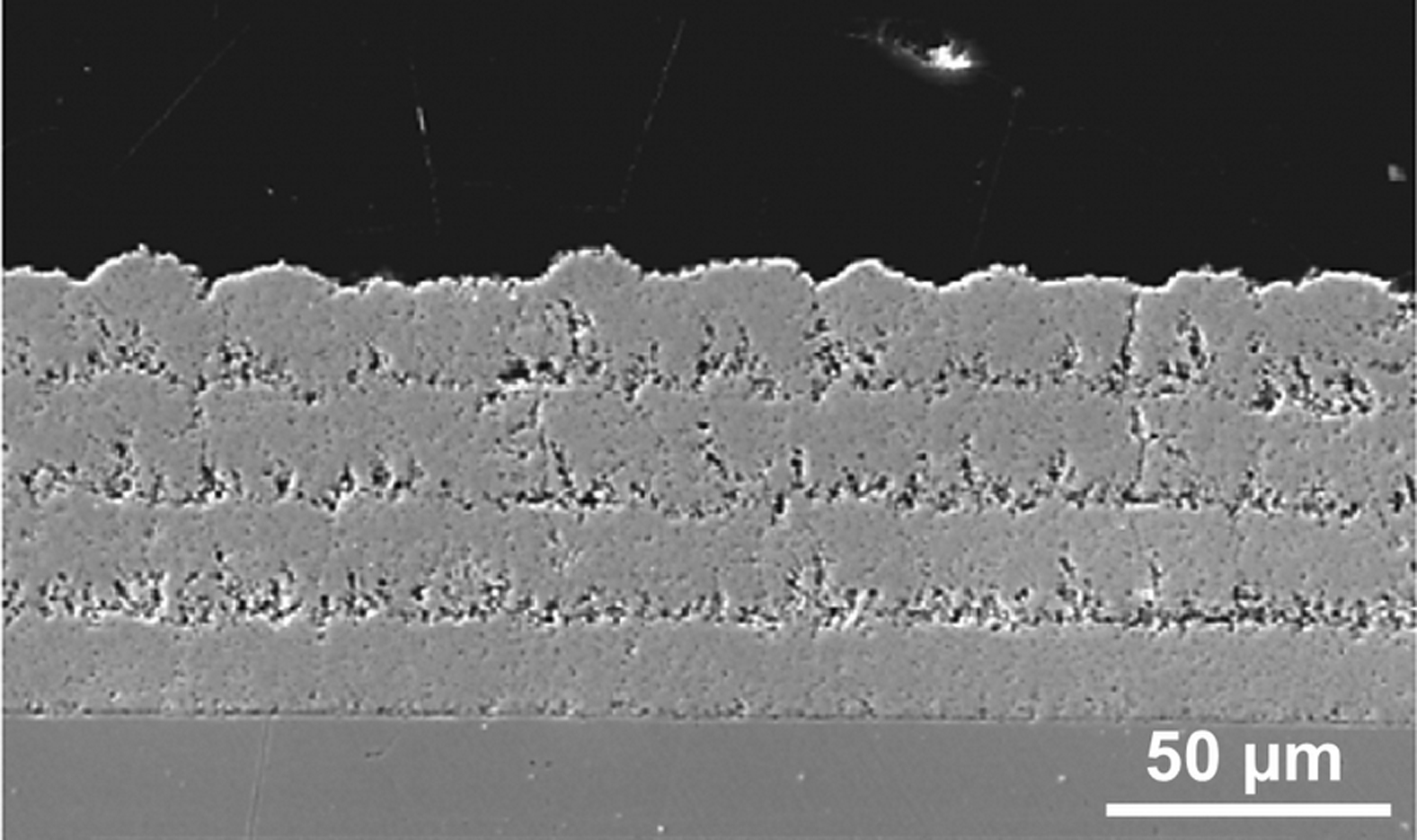
Cross-sections of suspension plasma sprayed ZrO2–7wt-%Y2O3 coating deposited in four passes. Reproduced from Fauchais et al. 105 with permission from Springer Science and Business Media
Microstructure: solution precursor thermal spray coatings
Contrary to nanocomposite coatings deposited by the previously discussed thermal spray processes, SPTS coatings do not exhibit distinguishable splat boundaries despite the presence of large splat-like deposits; 151,152 Depending on the spray conditions, SPTS coatings may comprise microstructural artefacts that result from the various stages of chemical reaction and thermal history of precipitates in the thermal spray jet; such as molten splats, hollow splats, spherical particles, fragmented shells, and unpyrolyzed particles; Fig. 25. Therefore, the microstructure would depend on the form of the particle just before impact; e.g. precipitated and molten particles form splats while supersaturated and unpyrolyzed particles form hollow or fragmented shells.
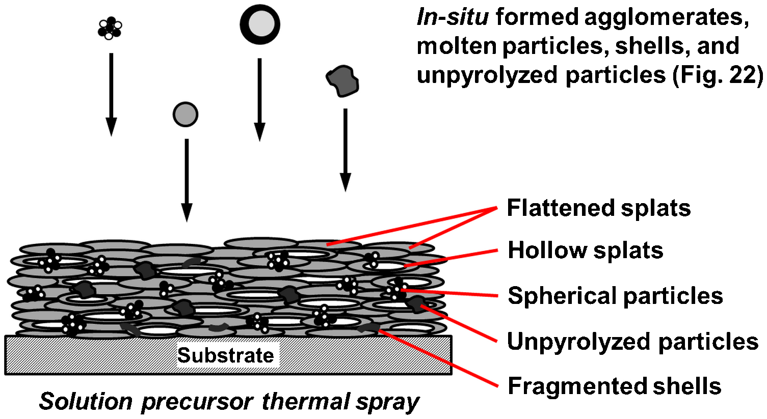
Schematic of nanocomposite coatings microstructure deposited by solution precursor thermal spray (SPTS) process
Similar to STS coatings, the microstructure of SPTS coatings also relies substantially on the extent of droplet fragmentation and penetration into the thermal spray jet. The factors influencing the degree of droplet fragmentation in SPTS are similar to those of STS, as described in the previous section. Generally, droplets below 5 μm will result in molten solid particles while larger particles are fragmented and deposited as unpyrolyzed particles. 105 Xie et al. conducted studies on the deposition mechanisms of SPTS coatings by studying deposits at different regions using a stationary torch 153 and single linescan arrangement. 154 Figure 26 depicts deposits that evolve from different degrees of penetration into the plasma jet.
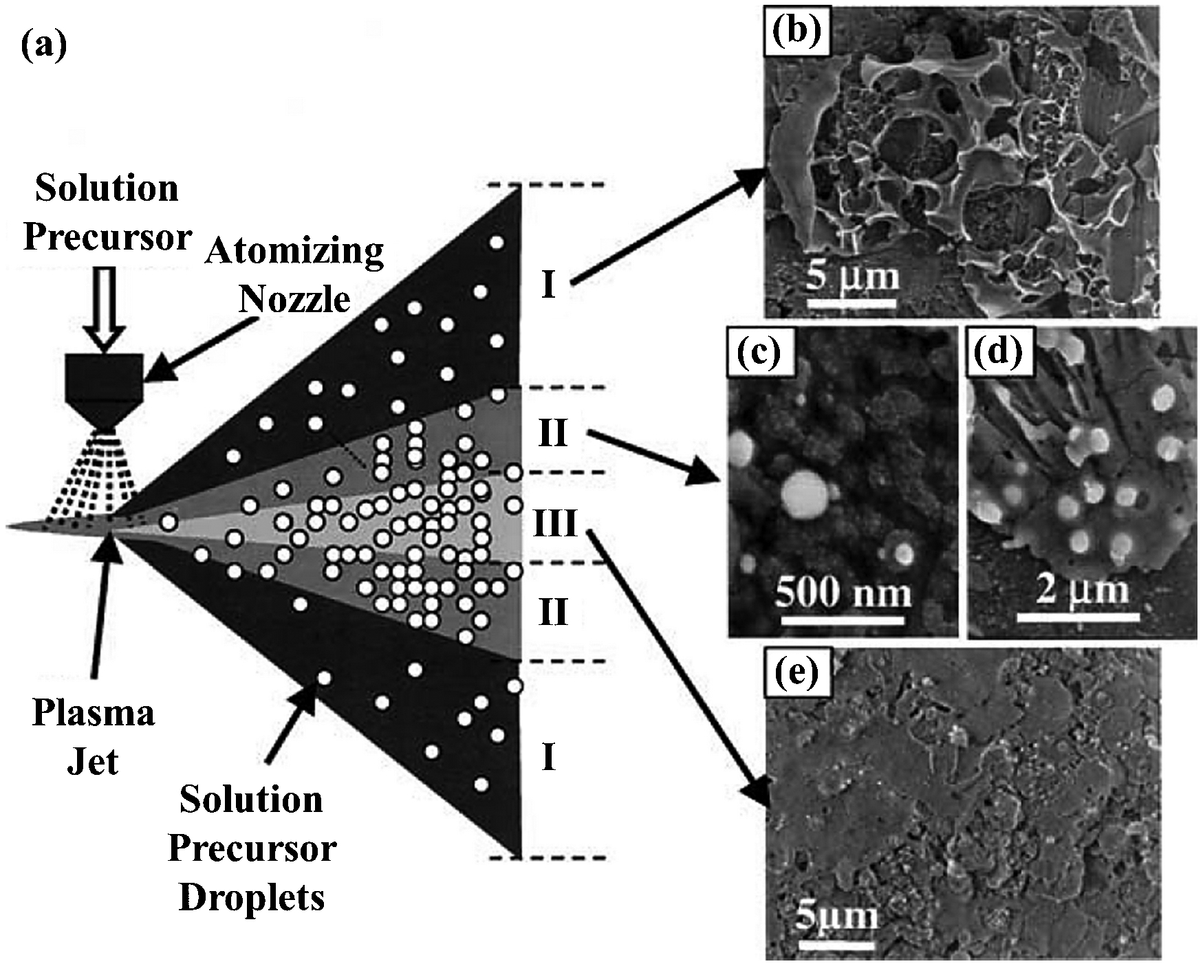
Solution precursor plasma sprayed ZrO2–7wt-%Y2O3 deposits: a Schematic of the temperature variations in plasma jet: (I) the periphery or cold region, (II) the moderately hot region, and (III) the core or hot region; b–e the corresponding deposits formed from the precursor droplets injected into different regions of the plasma jet. Reproduced from Xie et al. 154 with permission from Springer Science and Business Media
The precursor droplets that travelled in the periphery of the plasma jet (region I in Fig. 26a ) inflated, ruptured, and/or pyrolysed on impact with the substrate to form flakes, irregular agglomerates, or hollow shells; Fig. 26b . Thin films or fine spherical particles, Fig. 26c and d , were formed from the vaporisation and decomposition of precursor droplets that travelled in the moderately hot region (region II in Fig. 26a ). Precursor droplets that travelled in the plasma core (region III in Fig. 26a ) were melted and then solidified to form ultrafine splats; Fig. 26e . Deposition of particles from regions I and II will result in porous coatings, while those from region III result in dense coatings.
The solution concentration has a significant role in determining the rate of volumetric precipitation for dense particle formation in the SPTS process. Compared to spray pyrolysis, the rate of diffusion in SPTS is low compared to the rate of solute concentration increase through rapid solvent evaporation at the droplet's surface. 143,155 Hence, the volumetric precipitation in SPTS typically initiates at the droplet's surface because the surface has a much higher concentration than the droplet's core. 143 Consequently, solutions with high concentration will result in uniform precipitation and the formation of dense particles, hence deposition of high density coatings. On the other hand, solutions with a low concentration will lead to porous coatings because of the formation of shells and hollow particles as volumetric precipitation is less likely to propagate to the droplet's core; Fig. 27.
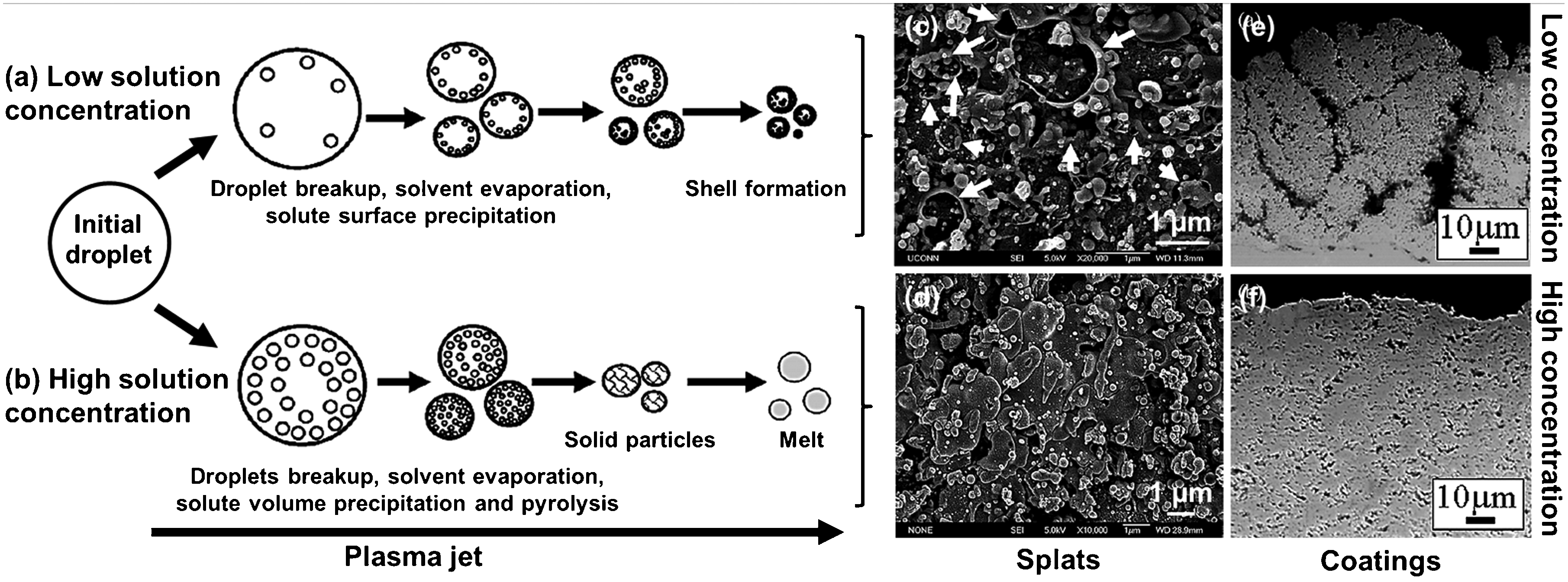
Schematics of droplets evolution in plasma jet at a low solution concentration and b high solution concentration. Solution precursor plasma sprayed ZrO2–7wt-%Y2O3 deposits: c and d are single scan band centre deposits collected at low and high solution concentrations, respectively; e and f are cross-sections of coatings deposited at low and high solution concentrations, respectively. Reproduced from Chen et al. 117 with permission from Elsevier
Low plasma power during SPTS causes incomplete chemical reaction and particle formation, thus the development of porous coatings. 156 On the contrary, a high plasma power will yield relatively dense coatings because of the increase of thermal energy that promotes pyrolysis and particle melting. However, an increase in plasma power may also cause the formation of cracks and pores because of significant splashing or splat disintegration. Such microstructures also arose from the formation of hollow particles because of high evaporation rates at the droplet's surface and rapid surface solidification at high plasma power. The mechanism of hollow particle formation at high power is similar to that determined for low solution concentrations, where the retained precursor within the hollow particles evaporates or pyrolyses upon impact with the substrate. Therefore, porous regions within coatings can be obtained by optimising the spray conditions to retain more particles with unpyrolyzed precursor, which will then contract to form pores upon pyrolysis. 151,157
Materials overview
The STS and SPTS methods have mostly been used to deposit ceramic and cermet nanocomposite coatings. Examples of nanocomposite coatings deposited by suspension and SPTS reported in the literature are summarised in Tables 5 and 6, respectively. As mentioned previously, plasma spray is the more commonly used thermal spray source in STS and SPTS, and will therefore be referred to as SPS and solution precursor plasma spray (SPPS) henceforth. The nanocomposite coatings presented in Tables 5 and 6 were deposited by plasma spray, with the exception of Al2O3–ZrO2 coatings, 145,158 which were deposited by suspension HVOF spray.
Materials and process comparison
From a general microstructural perspective, coatings deposited by spraying agglomerated nanocomposite particles through conventional approaches (plasma spray, HVOF, and detonation spray) reveal a mixture of fully molten splats, partially molten splats, and non-molten particles; while coatings deposited by cold spray consist of nanoparticles encapsulated within the deformed binder phase. Suspension thermal spray coatings are composed of dense nano-sized spherical particles and very fine splats that result from particle melting. SPTS coatings constitute a combination of flattened splats, hollow splats, spherical particles, unpyrolyzed particles, and fragmented shells, which result from the various routes of in-flight particle formation.
The versatility of thermal spray processes in depositing nanocomposite coatings, regardless of the form of feedstock materials, can be seen in the ‘Conventional approaches’, ‘Cold spray’, and ‘Suspension and solution precursor thermal spray’ sections. A wide range of nanocomposite materials, from ceramic matrix to metallic and polymer matrices, were deposited using conventional plasma spray, HVOF, cold spray, STS, and SPTS processes. The thermal spray processes used to deposit nanocomposite materials are compared in Table 11 based on the analysis of published work. It can be deduced from Table 11 that most of the materials reported are specific to the deposition method, with the exception of several commonly used materials; e.g. Al2O3–MWCNT, Al2O3–Ni, Al2O3–(ZrO2–Y2O3), AlSi–MWCNT, FeCrB–CrB2, NiO–(ZrO2–Y2O3), TiO2–HA, WC–Co, and ZrO2–Y2O3.
Summary of published work on nanocomposite coatings deposited by various thermal spray techniques
HA: hydroxyapatite; PC: polycarbonate; PEEK: polyether ether ketone; PEG: polyethylene glycol; MWCNT: multi-walled carbon nanotube; ND: nanodiamond; SS: stainless steel.
Each process has specific material requirements because of the feedstock characteristics and variations in process temperature and velocity. In general, conventional flame spray and HVOF processes are employed to deposit cermets of polymer matrix materials such as Fe–epoxy, Nylon-nanodiamond, Nylon–SiO2, Al2O3–NiCr, and TiB2–NiCrSiB, because of their relatively low processing temperature. Conventional plasma spray, which has a jet temperature of up to 15 000 K, is mostly used to deposit ceramic nanocomposites such as Al2O3–TiO2, Al2O3–ZrO2, Y2O3–MgO, and ZrO2–Y2O3. Detonation spray was also used to deposit ceramic nanocomposite coatings; e.g. Al2O3–TiO2 and WC–Co. 159–161 On the other hand, wire arc sprayed nanocomposite coatings have been limited by the commercial availability of nanostructured feedstock, and are typically formed from metal alloy cored wire that forms carbides, borides, and/or oxides through in-flight reaction and embedment within the metallic matrix. 96,162–166
Cold spray is typically used to deposit composites with a ductile phase to encapsulate ceramic particulates because of its high particle velocity and the lack of a molten phase; e.g. Al–Al2O3, Al–B4C, HA–PEEK, and TiB2–Cu. The STS process is mostly used to deposit ceramic nanocomposites that can form stable suspensions with the aid of dispersants and/or plasticisers, for instance, Al2O3–ZrO2, NiO–ZrO2, TiO2–HA, and Y2O3–MgO. On the other hand, SPTS is used to deposit materials that can be synthesised from precursors to form nanocomposites in-flight; e.g. Al2O3–Ni, NiO–ZrO2, Si–TiO2, TiO2–HA, and ZrO2–Y2O3.
Nanocomposite coatings
Al2O3–TiO2
Thermal sprayed alumina–titania coatings are typically applied to structural materials or machinery for protection against abrasive and erosive wear, cracking, spallation, or corrosion. 53,121,124,167 Nanocomposite Al2O3–TiO2 coatings have demonstrated improved wear resistance by up to eight times compared to its conventional counterparts. 167–170 The improvement in the microstructure and properties of this composite stems from the fact that addition of TiO2 to Al2O3 lowers the overall melting point of the composite; thus lowering the particle viscosity and interlamellar contact of the splats compared to individual ceramic coatings. 167,168 Various compositions of Al2O3–TiO2 nanocomposite coatings have been reported, including Al2O3–3wt-%TiO2, 171 Al2O3–8wt-%TiO2, 121 and Al2O3–13wt-%TiO2. 169 However, the majority of the studies of Al2O3–TiO2 coatings have concentrated on Al2O3–13wt-%TiO2, since this composition was shown to be optimal for wear resistance. 168
Nano-Al2O3–13wt-%TiO2 coatings have been mainly deposited by plasma spray, since ceramic coatings and their composites are conventionally deposited by plasma spray because of its high temperature. However, HVOF 167 and detonation spray 159,160 have also been used to deposit Al2O3–13wt-%TiO2 nanocomposites to create a variation of microstructure and phases that present significant changes in mechanical and tribological performance of the coatings. Conventional commercial coatings deposited using Metco 130 powder, 172 which exhibit splat quenched single phase γ-Al2O3 with clear splat boundaries and contrast between splats as a result of chemical inhomogeneity, 168,173 are almost exclusively used as the benchmark in studies of nano-Al2O3–13wt-%TiO2 coatings.
Alumina–titania, Al2O3–13wt-%TiO2, nanocomposite coatings were deposited by Gell et al. 123–125 via plasma spray of spray dried and heat treated nanoparticles. The coatings exhibited two distinct regions: (i) the fully molten regions that consisted of splat quenched γ-Al2O3 in nano- and sub-micrometer-sized columnar grains, and (ii) the partially molten regions that consisted of liquid phase sintered α-Al2O3 nanoparticles embedded in γ-Al2O3 matrix. Subsequent work on plasma sprayed Al2O3–13wt-%TiO2 nanocomposite coatings have similar findings. 168,173,174 Microstructural comparisons between conventional and nanostructured Al2O3–13wt-%TiO2 coatings are shown in Fig. 16. Metastable γ-Al2O3 is formed from fully molten particles because of the high cooling rate, while non-molten or partially molten particles retained the stable α-Al2O3 phase from the original feedstock. 125,169
Although all the reports agreed that TiO2 phase does not appear on analysis of these coatings, there were different views on the final phase of TiO2 within the coatings: i.e. (i) Ti4+ dissolved in γ-Al2O3 to form a solid solution; 124 (ii) TiO2 melted preferentially because of its lower melting point, with limited dissolution of α-Al2O3 into liquid TiO2; 175 and (iii) the formation of non-equilibrium χ-Al2O3 TiO2 phase where the Ti ions randomly occupy the Al3+ lattice sites in γ-Al2O3. 123,171 The inconsistencies concerning the TiO2 phases in coatings could arise because of the variation of volume fraction of TiO2 in the initial feedstock; which, according to the phase diagram, could alter the solubility of TiO2 in Al2O3.
The variation of microstructure and phases of plasma sprayed Al2O3–13wt-%TiO2 as a function of critical plasma spray parameters (CPSP) has been studied extensively by Gell and co-workers. 123–125,169,175 The term CPSP is defined by the ratio of power to primary gas flowrate. Generally, the fractions of γ-Al2O3 phase increased with an increase of CPSP until it reached a maximum at CPSP = 390. The γ-Al2O3 phase started to decrease with a further increase in CPSP. 124,125 The increase of CPSP caused an increase of particle temperature, and consequently the increase of volume fractions of the fully molten region and γ-Al2O3 phase. Beyond the maximum CPSP, γ-Al2O3 phase started to decrease and gave rise to α-Al2O3, indicating the occurrence of solid state transformation of γ-Al2O3 to α-Al2O3 phase beyond a certain particle temperature.
In comparison to the plasma spray system, HVOF deposited particles exhibited a narrow range of in-flight particle temperature and velocity distribution, hence contributing to a more uniform and consistent coating microstructure. 167 Conventional HVOF coatings were reported to outperform the best plasma sprayed hybrid (i.e. a combination of nano- and sub-micrometre feedstocks) Al2O3–13wt-%TiO2 coatings in terms of abrasion wear resistance and crack propagation resistance. 167 Nanoparticles achieved approximately 10% higher temperature and velocity than micrometre-ranged particles using the same set of spray parameters because nanoparticles are more porous, have a large surface area, and better capacity to absorb heat. An eight fold improvement in wear resistance was observed in HVOF nanostructured Al2O3–13wt-%TiO2 coatings. 167 Wear mechanisms of nanostructured coatings will be discussed further in the ‘Tribological properties’ section. The high performance of HVOF coatings compared to plasma sprayed coatings could also be attributed to the variation in phase transformation in both processes. However, no correlation was drawn out in the literature and the phases of HVOF sprayed Al2O3–13wt-%TiO2 coatings were not reported.
Detonation spray has been used to deposit discontinuous Al2O3–13wt-%TiO2 coatings with alternate layers of micro- and nanostructured components, 159,160 which present an advantage in terms of inhibiting through-thickness crack propagation. The distinctive microstructure of detonation sprayed coatings compared to plasma sprayed coatings is caused by the significant variations of thermal and kinetic states of particles between the two processes. 159 In detonation spray, there is a natural tendency for segregation of particles with different sizes, where smaller particles are accelerated by the detonation wave and deposited first. Smaller particles also reach a higher temperature and undergo significant melting compared to larger particles.
The thermal and kinetic behaviour of dense and porous particles of differing particle size causes the formation of a bimodal microstructure that is dense near the substrate and loosely bonded towards the surface; Fig. 28. In a fashion similar to plasma sprayed coatings, the nanostructure is retained through deposition of large non-molten or partially molten particles, where TiO2 melts and forms a liquid sintering phase around unmolten Al2O3 particles. 160 Although γ-Al2O3 is still present in detonation sprayed coatings, the amount of γ-Al2O3 phase is lesser than α-Al2O3 and, in comparison to plasma sprayed coatings, arises as a result of less melting. 159 The higher particle velocity in detonation spray results in denser coatings with higher hardness compared to plasma sprayed coatings. As well, detonation sprayed Al2O3–13wt-%TiO2 nanocomposite coatings exhibit an increase of 30–60% in hardness compared to conventional coatings. 159
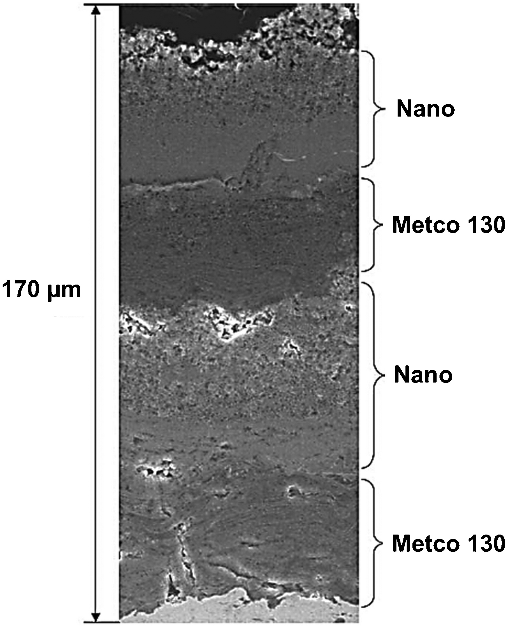
Microstructure of detonation sprayed multi-layer Al2O3–13wt-%TiO2 coating with alternating conventional and nanostructured layers. Reproduced from Cetegen et al. 160 with permission from Elsevier
Al2O3–(Y2O3)ZrO2
The low thermal conductivity of zirconia makes it an attractive material in thermal barrier applications. However, the transition of zirconia between its three polymorphs as a function of temperature causes significant defects when cooled from high temperature. The equilibrium stable phase for zirconia at room temperature is monoclinic; which transitions to tetragonal and cubic phases as the temperature increases. Upon cooling, volume expansion occurs on phase transformations from cubic to tetragonal to monoclinic, which results in stress formation and eventually cracks. Stabilisers, such as yttria, are added to stabilise the tetragonal phase and hinder the transition to monoclinic phase; thus giving rise to YSZ. The two most widely sprayed YSZ compositions are the 7YSZ (ZrO2–7wt-%Y2O3) 120,122,176 and 8YSZ (ZrO2–8wt-%Y2O3), 147,177 which are widely used in thermal barrier and solid oxygen fuel cell (SOFC) applications, respectively.
Nano-YSZ coatings have been deposited by conventional, 120,122,170 suspension, 147,177,178 and SPPS. 101,151,179 While plasma sprayed nano-YSZ coatings exhibit a bimodal microstructure, SPPS YSZ coatings were composed of fine splats; namely diameters of 0·5–5 μm with evenly spaced vertical cracks and nano-sized pores, which may be contrasted to a 50–100 μm splat size for conventional plasma spray coatings. The through-thickness vertical microcracks in the SPPS ZrO2–7wt-%Y2O3 coating depicted in Fig. 29 is a unique microstructural artefact introduced to impart strain tolerance in thermal barrier coatings. Such a microstructure contributed to low conductivity, high durability from increased strain tolerance and toughness, and improved thermal cycling life of coatings. 152,179 The spallation life of the coatings was improved by 2·5 times compared to conventional plasma sprayed coatings of the same bond coat and substrate, although the failure mode of SPPS coatings is similar to that of conventional coatings. 179
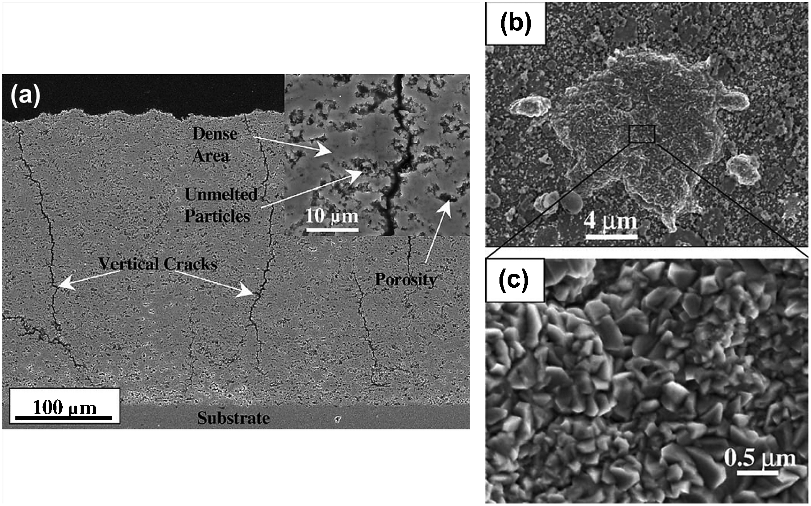
Solution precursor plasma sprayed ZrO2–7wt-%Y2O3 coatings: a cross-sectional view, b top view highlighting splat-like feature, and c higher magnification of b highlighting the equiaxed, nano-sized grains. Reproduced from Xie et al. 153 with permission from Elsevier
Suspension plasma sprayed YSZ coatings exhibited unmelts, partially molten, and resolidified particles within the coatings, which could be minimised by optimising the heat transfer, particle fragmentation, and particle trajectory through the variation of spray distance, injection velocity, injection location, solid loading, and plasma enthalpy. 147 At high magnification, the splat-like deposit revealed angular nanometre-sized grains ranging from tens to hundreds of nanometres. 153 Despite having more than one constituent, and therefore qualify as a composite, nano-YSZ will not be discussed further because the free yttria content in YSZ is minimal and localised compared to non-transformable tetragonal zirconia that it has not been detected in most studies, 156,180,181 but was only indexed sporadically by selected area diffraction (SAD). 151 This section will, therefore, focus on YSZ composites with a significant alumina component; i.e. Al2O3–ZrO2.
Alumina was incorporated in YSZ to enhance the abrasion, wear, oxygen diffusion, and thermal resistances of conventional YSZ coatings. 158 Addition of Al2O3 has been evidenced to limit the grain growth of ZrO2 during heat treatment, where grain growth of 7YSZ is three times greater than Al2O3–40wt-%ZrO2. 182 The restricted growth of ZrO2 was attributed to (i) the limited solid solubility of Al2O3 and ZrO2, where the two phases are mutually soluble only after melting; and (ii) the increased diffusion path relative to single phase oxides.
Similar to nano-YSZ coatings, Al2O3–ZrO2 coatings have also been deposited by conventional, 183,184 suspension 109,148 and SPPS. 140,182 The rapid solidification of thermal spray processes is conducive to the extension of the Al2O3–ZrO2 solid solution to form metastable amorphous phases, which could potentially (i) exhibit unique microstructures that would reflect on the electrical, optical, magnetic, thermal and mechanical properties; 185–187 and (ii) provide a reservoir of chemical species for surface chemical reactions during heat treatment. 140 The amount of Al2O3 incorporated in Al2O3–ZrO2 nanocomposites ranged from 5 to 80 wt-%. 183,184 Most studies on Al2O3–ZrO2 coatings have examined the near eutectic composition of Al2O3–40wt-%ZrO2, where the eutectic point of the Al2O3–ZrO2 pseudobinary system is 58wt-%Al2O3. 188–190 The near eutectic composition is favoured because the lowered melting point compared to pure Al2O3 and ZrO2 promotes the formation of a nanostructured, metastable solid solution.
Plasma sprayed Al2O3–ZrO2 nanocomposite coatings were characterised by a typical bimodal microstructure composed of nanozones of unmolten and partially molten particles, and a dense molten region. 191 The main difference identified between nanostructured and conventional coatings was the distribution of pores, where nanostructured Al2O3–ZrO2 coatings exhibited a homogeneous pore distribution of equal size compared to the wide and inhomogeneous pore distribution of conventional coatings. 183 The difference in homogeneity of pore distribution, in addition to the influence of grain boundaries, contributed towards greater load carrying capacity and less fluctuations of hardness and elastic modulus values in nanocomposite coatings compared to their conventional counterparts. 183 The molten regions of coatings revealed the lamellar structure of typical thermal sprayed coatings, 192 although nanostructured coatings indicated better chimerism between lamellar interfaces compared to conventional coatings because of more homogeneous melting. 183
Most studies have reported t-ZrO2 to be the main phase of as-sprayed coatings with metastable γ-Al2O3, although small amounts of m-ZrO2 192 and c-ZrO2 183 have also been found. Such discrepancies are most likely caused by the differences in composition, initial phase of the feedstock, and/or feedstock processing. The main phase of ZrO2 in the feedstock is mostly retained in plasma sprayed coatings in the presence of Y2O3 and/or Al2O3. Yttrium ions are more stable substitutional solutes in ZrO2 compared to aluminium ions because of their larger ionic radius, thereby making it a more effective stabiliser. However, the use of Al2O3 as an additional stabiliser significantly reduced the content of metastable γ-Al2O3, which tends to nucleate in favour to α-Al2O3 upon solidification by virtue of its low nucleation and interfacial energy for transformation. 184,193 Addition of other high melting point oxides and carbides; e.g. MgO and SiC, has also been known to give rise to α-Al2O3 formation by increasing the amount of available unmolten, nucleation sites. 184 Such escalation in α-Al2O3 content, in addition to the dense nanostructure, contributed to an increase of coating hardness, wear and corrosion resistance. 184,194
The SPS process has been used to engineer Al2O3–ZrO2 nanocomposite coatings with different architectures; e.g. dense or porous, graded porosity or composition, and finely structured multi-layers. 195 The varying architecture is achieved by adjusting the interrelated operating parameters: (i) heat and momentum transfer to the particles (related to the plasma gas mixtures), (ii) particle momentum and thermal inertia (related to particle size and spray distance), and (iii) heat flux imparted by the plasma flow to the substrate and previously deposited layers. The plasma auxiliary gas, plasma current, gas flowrate, gas composition, feedrate, particle size distribution, and solid loading contribute to the particle temperature and velocity profiles, which consequently influence phase formation in the coatings. 148 Low particle velocity (<650 m s−1) favours the formation of stable α-Al2O3 and tetragonal ZrO2 phases while high particle velocity (>750 m s−1) favoured the formation of metastable γ-Al2O3 and cubic ZrO2 phases. 108
The SPS Al2O3–ZrO2 coatings were dense, with dense spherical particles of ∼100 nm and ultrafine splats that exhibit similar morphology to conventional plasma sprayed coatings but is more refined; i.e. 1–5 μm compared to 100–150 μm in conventional coatings. 146 Despite having a molten phase, indicated by the presence of ultrafine splats, SPS coatings did not reveal the presence of γ-Al2O3 phase that is observed in conventional plasma sprayed nanocomposite coatings, as the metastable phase was transformed to α-Al2O3 by the convective flux of the plasma jet at the coating surface because of the short spray distance. 194 The α-Al2O3 and tetragonal ZrO2 grains were distributed homogeneously in SPS coatings, while the conventional coatings showed distinct boundaries between the immiscible Al2O3 and ZrO2. 194
Suspension plasma sprayed Al2O3–ZrO2 coatings were highly crystalline and composed of fine lamellae of alternating Al2O3 and ZrO2 layers with segregated crystalline phases. 158 The segregation arose because of the high affinity of ZrO2 to the solvent over Al2O3, which allows the solvent to entrain ZrO2 particles as it flows from the core to the droplet surface during evaporation. On the other hand, suspension HVOF sprayed coatings were amorphous and revealed uniformly dispersed ZrO2 particles in an Al2O3–ZrO2 matrix. 158 Figures 30a and 30b show the microstructure of granular and lamellar structured Al2O3–ZrO2 coatings deposited by high velocity suspension flame spray and SPS, respectively. The finely dispersed ZrO2 particles in HVOF sprayed coatings in addition to its larger grain sizes, when compared to SPS coatings, indicate that the particle temperature was lower and the melting was incomplete. As a consequence, SPS coatings exhibit high hardness and high abrasion resistance, while suspension HVOF sprayed coatings show low thermal diffusivity and high erosion resistance.
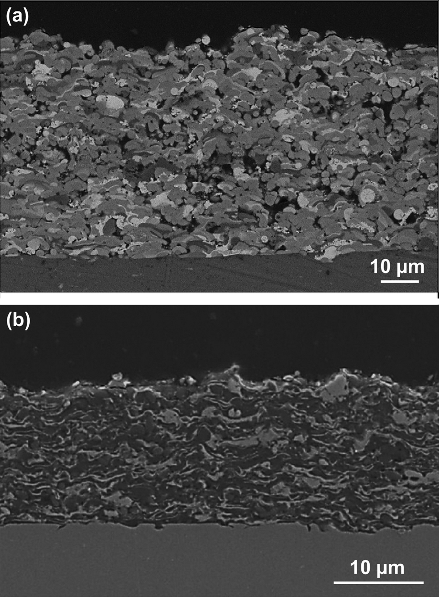
Porous Al2O3–40wt-%ZrO2 nanocomposite coatings were produced by using helium in place of hydrogen as the secondary plasma gas; 148 Fig. 31. The porosity content was increased from 0% in the crack free regions of the hydrogen-deposited coatings to a maximum of 8% in helium-deposited coatings. The increase of plasma stability with the use of helium, coupled with its high conductivity generates a wider plasma jet core that promotes the deposition efficiency of fine particles. Dense coatings deposited by STS tend to develop microcracks from thermal stress relief upon cooling. This arises because of the short spray distance and greater number of passes needed to attain the required thickness in STS compared to conventional thermal spray. These different thermal spray parameters may generate higher temperature on the coating surface, namely 860°C compared to ∼200°C for conventional thermal spray processes; 104 Fig. 31a . Coatings with uniformly distributed porosity are desirable in applications such as thermal barrier coatings, abrasive coatings, and the anode layer of solid oxide fuel cells.
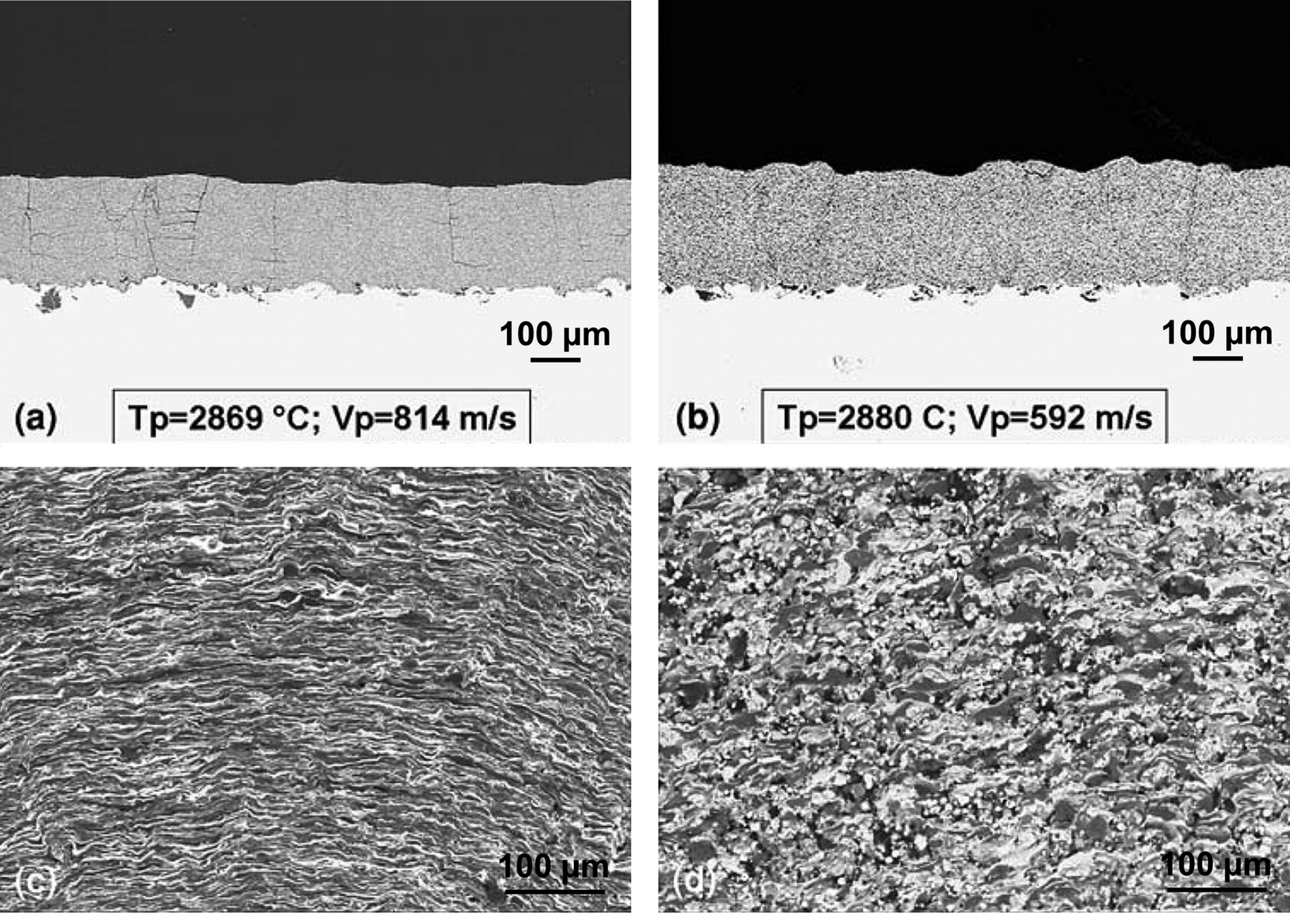
Suspension plasma sprayed Al2O3–40wt-%ZrO2 coatings deposited using a hydrogen and b helium as secondary gas. c and d are the same coatings as a and b, respectively at 2 000× magnification. 148
On the contrary, nanocomposite ZrO2–10mol.-%Al2O3 coatings deposited by SPPS exhibited three distinct microstructural features; Fig. 32. The coatings were dominated by (i) a nanostructure (region 1 in Fig. 32), and (ii) a sub-micrometre structure (region 2 in Fig. 32); with (iii) some large spherical grains (region 3 in Fig. 32). 140 The nanostructured regions were composed of distinct fine (∼10 nm) and coarse (10–40 nm) nanostructured zones that consist mainly of t-ZrO2 phase, with some m-ZrO2 grains in the coarse nanostructured zones. The metastable t-ZrO2 phase was formed as a result of stabilisation by Al3+ in the ZrO2 solid solution. The sub-micrometre regions were composed of 50–100 nm twinned or equiaxed grains of m-ZrO2 phase. The occasional large spherical grains were primarily orthorhombic zirconia, ‘o-ZrO2 phase’, ranging from 0·3 to 1 μm. Formation of o-ZrO2 phase was speculated to arise from aqueous reaction in the mesoporous zirconia-containing precursor. Amorphous aluminium-rich phase was found at the grain boundaries in the form of intergranular pockets.
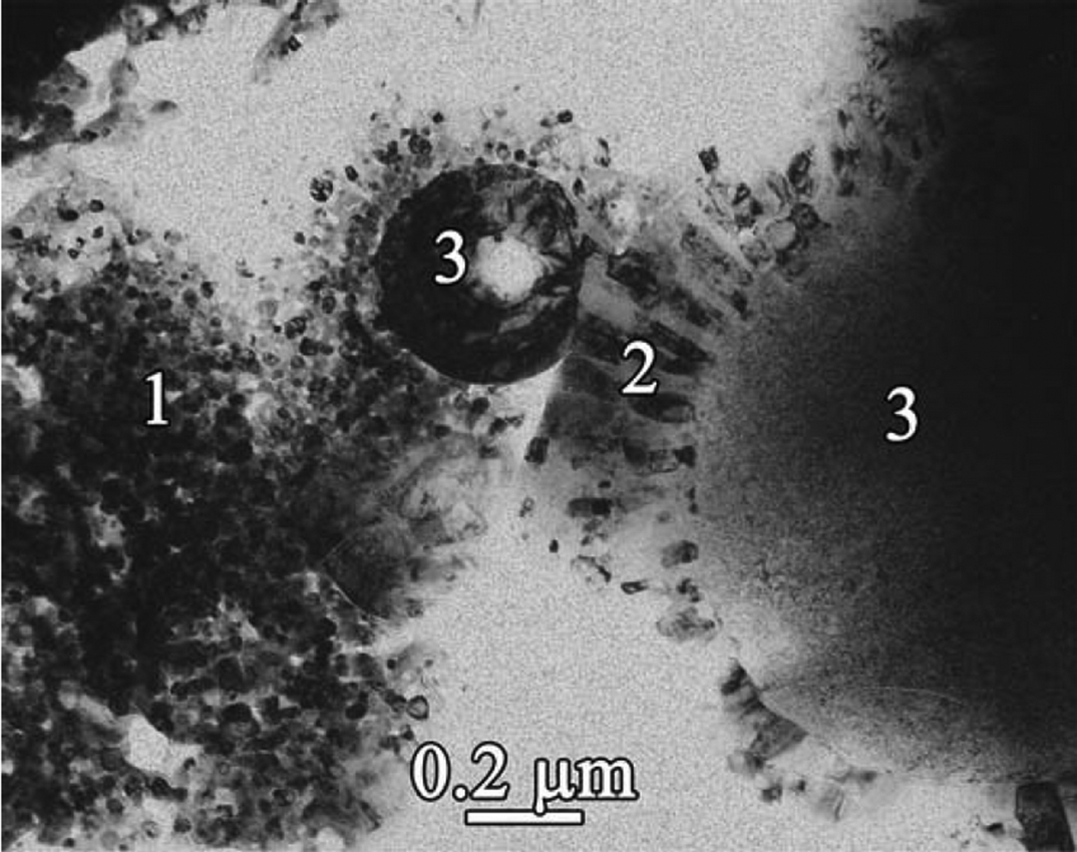
Transmission electron microscope bright-field images of solution precursor plasma sprayed ZrO2–10mol.-%Al2O3 coatings exhibiting three types of structures: (1) nanostructure, (2) sub-micrometre structure, and (3) large spherical grains. Reproduced from Vasiliev et al. 140 with permission from Elsevier
The presence of amorphous phase surrounding the nanocrystalline grains in plasma sprayed, SPS and SPPS nano-Al2O3–(ZrO2–Y2O3) coatings contributed largely towards the decrease in thermal diffusivity, 192 because of improved phonon scattering and internal boundary scattering. 196 In addition, nanograins provide a larger grain boundary volume for phonon scattering by virtue of its comparable crystallite size to the mean free path of phonons. Thermophysical properties of thermal sprayed nanocomposite coatings will be discussed further in the ‘Thermophysical properties’ section.
WC–Co
Tungsten carbide, WC, is well known for its exceptional hardness and wear resistance. These hard but brittle carbide particles are frequently bound by a ductile metal matrix, most commonly cobalt, to improve the fracture toughness. Tungsten carbide–cobalt, WC–Co, is hence used extensively in applications that require resistance against abrasion, sliding, fretting and/or erosion; 52,53 e.g., drills, gears, pistons and valves. Physical properties such as hardness, strength and wear resistance of WC–Co depend largely on the WC grain size and volume fraction. 197 For thermal spray coatings, such properties are also determined by the porosity and phase composition of the carbide and binder phase. 197
While the WC grains in cemented carbides tend to form a continuous network of contacting particles within the cobalt matrix, 198 the carbide particles in thermal spray coatings are more discrete because of the relatively high cobalt content used in thermal spray feedstock and the loss of WC during deposition. 197 The nominal content of cobalt in thermal spray coatings is typically 12 and 17 wt-% compared to the range of 6–10 wt-% used for sintered materials. 197 The most commonly deposited WC–Co composite coating is WC–12Co, which has been deposited via HVOF, 199 detonation spray, 161 cold spray, 133,200 and SPS processes. 113 Nanocomposite coatings with nominal compositions of WC–15Co 201,202 and WC–17Co 135,137 have also been documented.
Generally, WC–Co tends to undergo a combination of decarburisation, oxidation, reduction, and dissolution reactions when deposited by conventional thermal spray processes, such as plasma spray, HVOF, and detonation spray, because of the high processing temperature. Hard and brittle phases such as W2C, W, and CoxWyCz, and WO3 were found in thermal spray WC–Co coatings. 197 During spraying, cobalt is melted first, followed by the dissolution of carbon from the edges of WC grains into cobalt which leads to decarburisation of WC particles. Upon impact and cooling, W2C, W, and the remaining WC precipitate from the melt while the remaining liquid forms an amorphous matrix that contains W, C, and Co; 201 Fig. 33.
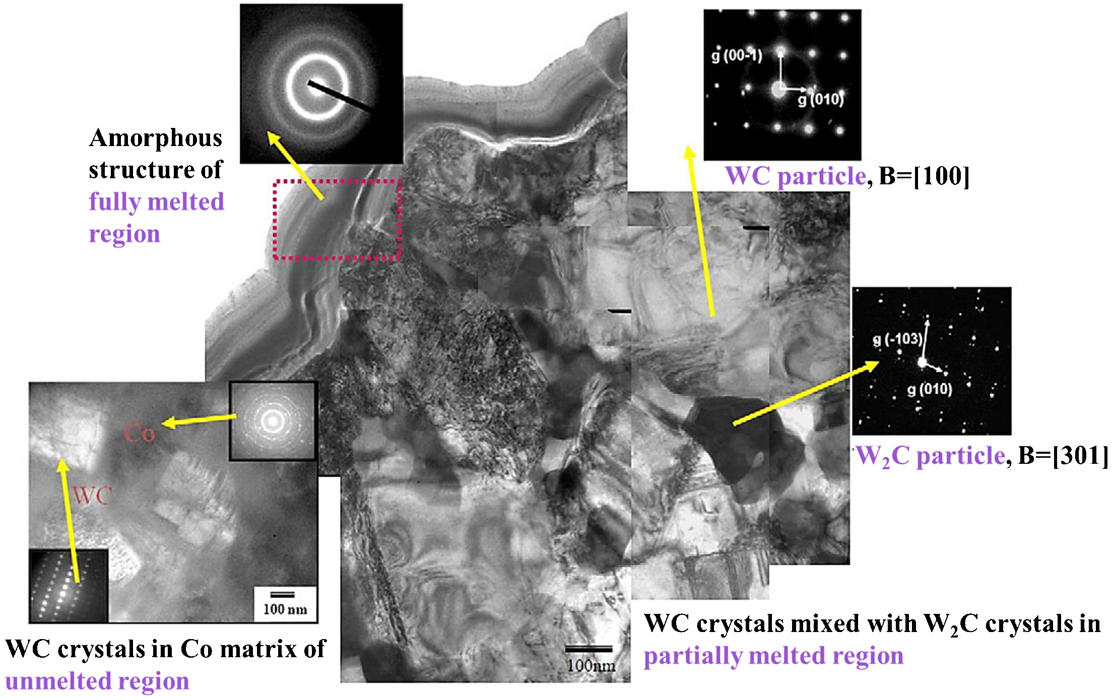
Transmission electron micrograph of nanostructured tungsten carbide–cobalt, WC–Co coating deposited by detonation spray, depicting different phases in regions at different melting states. Reproduced from Lim et al. 161 with permission from Elsevier
Nanocomposite WC–Co coatings underwent greater degrees of decomposition and dissolution to form W2C and W compared to conventional coatings owing to the greater surface area to volume ratio of nano-WC particles. 161,201 The carbon content decreased by 41% for nanocomposite WC–Co coatings compared to only a 24% reduction in conventional coatings. 201 The crystallinity index of nanocomposite WC–Co is also lower than that of conventional coatings. 201 Despite having significantly higher deposition efficiency (>70%) 199 and improved hardness compared to conventional coatings, the greater decomposition to form brittle phases in nanocomposite WC–Co coatings led to their inferior wear resistance. 198,202 In addition, the fine WC grains in nanostructured coatings resulted in rapid pullout of the hard phase and high wear rates compared to larger WC grains that were more resistant to removal by relatively smaller abrasive particles. 203
Achieving the right balance of melting would produce good bonding while limiting the degradation and other reactions between constituents in the coating, to produce a more wear resistant matrix phase. This is usually achieved by regulating the process parameters such as the agglomerate size, fuel chemistry, and oxygen–fuel ratio. 204 Another approach is to apply a protective layer over the feedstock particles; e.g. cobalt-coated WC–Co particles, where the thin protective layer effectively shields WC particles from direct exposure to the oxidising flame; thereby minimising the degree of WC decomposition and limiting excessive particle melting. 205
Cold sprayed WC–Co coatings are favoured over the conventionally deposited coatings because the WC particles do not undergo high temperature phase transformation into hard and brittle phases. In fact, nanostructured WC–Co coatings are the most widely reported nanocomposite coatings deposited by cold spray. The coatings did not exhibit any evidence of phase transformations or degradation because the deposition occurred in the solid-state. 133,135 However, building up of WC–Co coatings by cold spray has been difficult compared to deposition by HVOF and detonation spray because of the poor deposition efficiency of the WC particles.
The use of nanostructured feedstock significantly improves the deposition efficiency and density of cold sprayed WC–Co coatings. 137 Crack-free WC–Co coatings with a porosity of <3·8% and thickness up to 900 μm have been deposited by cold spraying agglomerated nanostructured feedstock. 135,137 The coatings also exhibited a more smooth coating-substrate interface compared to conventional coatings. 137 This outcome arises because (i) the critical velocity is lowered and (ii) the contact area between the Co binder and WC particles was greater. Cold spraying of conventional feedstock using similar processing parameters resulted in erosion and/or grain refinement rather than deposition because of insufficient contact between the hard phase and binder. 137
On the contrary, SPS produced WC–Co coatings with variable porosity levels from less than 0·2 to 9%. 113 Coatings with low porosity revealed substantial degradation of WC–Co because of extensive melting of the particles, which caused a significant decrease in hardness. Similar to HVOF coatings of agglomerated WC–Co, the SPS coatings were composed of W2C, W3C, and W from the decomposition and reduction of the WC phase, along with the presence of a brittle amorphous cobalt phase.
Distinct carbide degradation during the SPS process is indicated by the decrease in carbon content and low crystallinity. The high particle temperature, in addition to the large surface area of fine carbide particles in the SPS process, increased the surface reactivity of the particles for oxidation and rapid dissolution of WC grains. Thus, the degradation of carbides and binder can be restricted by lowering the particle temperature; e.g. varying the suspension feedrate or increasing the total thermal load.
CNT-reinforced nanocomposites
Carbon nanotubes have evolved as a material with exceptional mechanical, electrical, and thermal properties. 206–208 Physical properties of CNTs depend on their length, diameter, chirality, and orientations. 209–212 The high strength of CNTs, namely elastic modulus of ∼0·9 TPa and tensile strength of ∼150 GPa, 213,214 places them as a reinforcement candidate for composite materials. However, research on CNTs reinforced ceramic and metal matrix composites has been scarce compared to their polymeric counterparts because of the processing constraints in attaining composites with (i) homogeneous CNT dispersion, (ii) effective CNT retention in relation to chemical and structural stability, and (iii) good CNT-matrix interfacial bonding. 215
Thermal spray is emerging as a promising processing route to incorporate CNTs into ceramic and metal matrix composites, not only as coatings but also as bulk free standing components. Most CNT-reinforced composites are manufactured using MWCNTs, which consist of many single-walled CNTs that are arranged in a concentric manner. Conventional thermal spray processes, including flame spray, 83 plasma spray, 85,213 and HVOF, 215,216 as well as cold spray 138,139 have been used to deposit CNT-reinforced nanocomposites with ceramic and metal matrices; e.g. Al2O3, Al–Si, copper, stainless steel, and hydroxyapatite. Carbon nanotube-reinforced hydroxyapatite coatings will be discussed in the next section, because they require special considerations in relation to toxicology in biomaterial applications.
Free-standing CNT-reinforced Al2O3, 84,85,216 and hypereutectic Al–Si nanocomposites 217–219 with thicknesses over 1 000 μm were manufactured by HVOF and plasma spray forming. As lightweight CNTs are difficult to retain in the core of a thermal spray jet and are often lost as overspray, improving the feedstock flowability and deposition efficiency by using spray dried powder rather than blended ones enabled the thickness limit to be extended to 5 000 μm, 220 The different methods of CNT incorporation; i.e. agglomerated vs. surface dispersion, resulted in the variation of in-flight particle characteristics, and consequently the microstructure and properties. 221 Thermal spray formed CNT-reinforced nanocomposites are composed of a two-phase structure: (i) matrix containing uniform CNT distribution, and (ii) CNT-rich clusters. 215,220,222
The uniformity of CNT distribution in the structure relies on the composition of the feedstock. The degree of CNT clustering increased when the concentration of CNT increased, because of the formation of a CNT mesh through capillary action generated by the surface tension of the molten alloy matrix. 220 Formation of aluminium carbide, Al4C3, which will critically deteriorate the mechanical properties of the nanocomposite, was suppressed during thermal spray because of the thermodynamic stability of the cylindrical graphite-structured CNTs in the aluminium matrix at high temperature. 217 The bimodal grain matrix and crack bridging effects of the CNTs led to the improvement of fracture toughness of Al2O3–CNT by 43%. 85 The mechanical properties of AlSi–CNT were also enhanced by the CNTs, as well as primary silicon particle reinforcement. Plasma spray formed AlSi–MWCNT nanocomposite exhibited a porosity level that was twice that produced by HVOF; thus giving them lower hardness, H = 1·65±0·11 GPa and elastic modulus values, E = 55·5±9·6 GPa compared to HVOF coatings, H = 1·93±0·14 GPa and E = 82·8±9·3 GPa. 219 A greater extent of grain refinement of primary silicon particles deposited by HVOF also contributed to the better mechanical properties because they act as potential barriers to dislocation movement. 223
Apart from achieving a homogeneous CNT distribution, the CNT-matrix interfaces require low thermal resistance to take advantage of the high thermal conductivity of CNTs, 139 as well as good interfacial bonding for the shear stress transfer in short fibre reinforced composites. 138 Improvement in the wettability and interfacial adhesion between AlSi and CNTs was achieved through the formation of an ultrathin β-SiC layer at the AlSi–CNT interface, which promoted load transfer to the reinforcement phases. 218 Furthermore, CNT inclusions impeded grain growth by restricting grain boundary mobility through grain pinning and the formation of an interfacial amorphous layer. 222
Cold sprayed CNT-reinforced composite coatings exhibited homogeneously dispersed CNTs throughout copper 139 and Al–Si matrices. 138 The solid-state deposition of Cu–CNT coatings resulted in a dense microstructure and ‘clean’ interfaces with no intermediate amorphous compounds; thus exhibiting high thermal diffusivity compared to pure copper coatings. The fibre structure of the CNTs was retained after spraying, but the CNTs were moderately damaged from the impact and shear processes during milling 139 and deposition. 138 Defects such as kink formation, neck fracture and graphite layer peeling were reported.
The coating surface revealed protruded CNTs that were incorporated in the copper matrix to form a closely attached interface, while the length of CNTs at the cross-sections was maintained at several micrometres and located between elongated copper splats. In the case of AlSi–CNT coatings, the spray dried Al–Si particles that underwent disintegration during cold spray deposition fragmented the CNTs and both components were embedded and mechanically bonded to the aluminium matrix. The coatings exhibited a wide range of elastic modulus values because of inhomogeneous distribution of Si-rich regions as well as porosity that was transferred from the spray dried particles to throughout the coatings.
The manufacture of CNT-reinforced nanocomposites by suspension or SPTS has not yet been reported in the open literature. Nevertheless, the prospects and feasibility of these manufacturing routes are promising considering their capacity to achieve intimate CNT-matrix interfacial interactions at the molecular level of mixing. It is also worth noting that CNT-reinforced nanocomposites have been successfully fabricated through the spray pyrolysis process. 224
Hydroxyapatite-based nanocomposites
Research on plasma sprayed hydroxyapatite, HA [Ca10(PO4)6(OH)2], has become prominent in biomedical applications since its inception in the 1980s. 225–227 The structural similarity of HA to bone mineral, which constitutes 60–70 wt-% of natural bone, help promote the fixation and stabilisation at the bone-implant interface. 228–230 Despite the biocompatibility edge offered by HA, it lacks the mechanical strength to provide the load-bearing capacity required by biomedical implants. Thus, HA is customarily applied as a coating onto metal substrates, such as titanium alloys, to optimise the biological and mechanical attributes of the implants. Bioinert reinforcing materials, such as alumina and titania, are also incorporated to impart strength and toughness to brittle HA without compromising its biocompatibility and bioactivity. Hydroxyapatite has been doped with 5 wt-% silver and then incorporated with a polyether ether ketone (PEEK) matrix to produce nanocomposite coatings that impart substantial anti-bacterial properties to the coatings. 231
Nanostructured hydroxyapatite composite coatings have been demonstrated to not only exhibit superior mechanical performance, but also enhanced biocompatibility with osteoblast cells. 87 The improved biocompatibility was attributed to the effect of nanotexture or nanoroughness on the adsorption of proteins such as vitronectin and fibronectin. 232,233 These proteins mediate adhesion of anchorage-dependent cells such as osteoblasts and, therefore, increase cell reproduction on the surface. Various compositions of HA nanocomposites have been deposited by plasma spray, 234,235 HVOF, 236,237 cold spray, 231 SPS, 238,239 and SPPS; 240 with HA fractions ranging from 10 to over 95 wt-%. The biological and mechanical performance of HA nanocomposite coatings are phase-dependent and, thus, vary with the deposition process.
At high temperature (namely >1 000°C), hydroxyapatite undergoes decomposition to tricalcium phosphate, TCP (Ca3(PO4)2), tetracalcium phosphate, TTCP (Ca4P2O9), and calcium oxide (CaO), in addition to the formation of amorphous phase. 241,242 Dehydroxylation of HA also occurs to produce oxyhydroxyapatite, OHA and oxyapatite, OAp. 243 Such phases decrease the purity and crystallinity of HA in the coatings, and consequently result in expedited coating dissolution because these phases have much higher dissolution rates than HA; i.e. ACP≫TTCP>α-TCP>OHA>β-TCP≫HA. 243,244 Thus, HVOF is the preferred method of depositing HA nanocomposite coatings compared to other conventional thermal spray processes.
HVOF-deposited HA–ZrO2 nanocomposite coatings exhibited a layered and dense structure, with evenly distributed ZrO2 particles. 237 In addition to the high velocity deposition, the distribution of nano-ZrO2 particles at the HA splat interfaces also contributed to the low porosity. Limited particle melting was related to high crystalline HA phase retention, where the as-sprayed coatings revealed 74% crystallinity. Secondary phases such as α-TCP, t-ZrO2, and CaZrO3 were present in the coatings, although these same phases were also found in the feedstock; thereby indicating minimum phase transformation during the HVOF process. The absence of β-TCP, TTCP, and CaO further confirms the limited phase transformation of HA. 237 The significance of the melting fraction on the phase composition and properties of HA coatings has been discussed by Khor et al. 74
The lack of tetragonal to monoclinic ZrO2 transformation was favourable to improving mechanical properties, and was attributed to the limited heating of nano-ZrO2, rapid cooling and the formation of residual stress at the HA/ZrO2 zone during the quenching of molten particles. The presence of CaZrO3 phase suggests that there has been reaction between HA and ZrO2 during processing. However, the fraction of CaZrO3 phase in the coatings only increased 0·2 wt-% from the 1·0 wt-% in the feedstock; indicating that the majority of this phase arose during feedstock consolidation through SPS, rather than the HVOF deposition process.
On the contrary, HA–TiO2 nanocomposite coatings deposited by HVOF demonstrated significant phase transformation from anatase to rutile TiO2, where the amount of anatase decreased from 86% in the feedstock to 17% in the coatings. 230 This phase transition occurred because rutile is the most stable among all the polymorphs of TiO2. The retention of small amounts of anatase TiO2 in the partially molten zones greatly enhanced the mechanical and photocatalytic properties of the coatings. 236 Despite the fact that CaTiO3 has been found in HVOF HA–TiO2 coatings with similar compositions, 245 no such phase was detected in the nanocomposite coatings. 87,230
The absence of CaTiO3 phase in addition to the lack of thermal decomposition products of HA in the coatings arises because of (i) the insensitivity of XRD or masking by HA peaks owing to the low fraction of HA, i.e. ∼10–20 wt-% compared to 90 wt-% in HA–ZrO2 coatings, (ii) the short residence time in the HVOF jet, and/or (iii) the feedstock manufacturing process, where they were mechanically blended rather than chemically or thermally consolidated. However, there was some diffusion between HA and TiO2, which was indicated by the coexistence of titanium, calcium, and phosphorus atoms at microregions between adjacent HA and TiO2 splats. 87 Formation of such products from the chemical reaction between HA and TiO2 have been claimed to promote apatite growth. 87,245
In applications requiring photocatalytic performance, nanocrystalline anatase is more favourable as photocatalytic TiO2 is optimised in this form, 246 where it is most stable at particle sizes <11 nm. 247 While HA requires a low quenching rate to minimise the formation of secondary phases, formation of anatase TiO2 is favoured by a high quenching rate. A dual injection system that combines conventional powder feeding of HA and SPPS of TiO2 was used to overcome this exigency to deposit HA–TiO2 nanocomposite coatings that contained substantial anatase. 240 Despite the benefit of the novel injection system, the coatings maintained the presence of rutile TiO2 and traces of TCP, TTCP, and amorphous phases. Graded multi-layered HA–TiO2 coatings deposited by SPS also exhibited similar phases. 238 Such phases suggest that the anatase to rutile phase transformation at 400–1200°C 248 still occurs regardless of the shorter in-flight time of the particles in SPPS and SPS compared to conventional thermal spray processes.
The deposition of HA nanocomposite coatings by plasma spray, with the incorporation of CNTs, improved coating crystallinity from 53·7 to 80·4%. 234 The improvement in crystallinity stems from the fact that CNTs act as nucleation sites for the crystallisation of HA and aid the preservation of its inherent crystal structure. 249,250 During rapid cooling of the plasma spray process, thermal energy is isolated near CNT surfaces surrounded by HA melts because CNTs have three times higher thermal conductivity (∼3×10³ W m−1 K) than HA (∼0·7×103 W m−1 K). 234 This allows HA to nucleate over a longer duration in CNT-distributed regions compared to cooling in the absence of CNTs. Despite the improvement, the crystallinity of plasma sprayed HA–CNT coatings is lower compared to that of the feedstock. Transformation of HA to secondary phases was evident in the form of phosphate-rich needle-shaped regions. 234
While conventional plasma sprayed HA coatings exhibit the typical structure of molten splats, intersplat cracks, micro porosity, and partially fused particles; HA–CNT coatings constitute resolidified fine and nodular HA particles. The nodular particles in the nanocomposite coatings contributed to increased surface roughness, and consequently enhanced cell adhesion and growth. 235 The distribution and retention of CNTs in HA coatings were similar to that of other CNT reinforced coatings discussed in the ‘CNT-reinforced nanocomposites’ section, where the uniform distribution of CNTs in the coatings indicated maximum retention from the high temperature and velocity deposition. 234
Wear and fracture toughness were improved by up to 56% with CNT-reinforcement through the anchoring effects of CNTs. 235 The reinforcing mechanisms of CNTs will be discussed further in the ‘Mechanical properties’ and ‘Tribological properties’ sections. The variations of mechanical properties and in vitro behaviour of HA–CNT nanocomposites as a function of processing temperature, because of phase and microstructural changes, have been studied in detail by Xu et al. 251 There have been controversial views in relation to the benefits of CNTs in biomaterial applications. On the one hand, CNTs were demonstrated to enhance cell proliferation. 249,252 On the other hand, CNTs were found to exhibit toxicity in vivo. 253,254 The toxicology effects of thermal sprayed CNT-reinforced biocoatings will be discussed further in the ‘Biocompatibility and cytotoxicity’ section.
Polymer-based nanocomposites
Polymer-based materials are widespread as protective coatings in harsh environments, low friction insulation coatings, and functional coatings because of their cost effectiveness, low density, chemical inertness, as well as high tensile strength. The inclusion of reinforcing filler results in composite coatings with enhanced mechanical and tribological thermal properties. 255,256 However, conventional polymer processing techniques often require the use of volatile organic solvents and have limited on-site applicability for large surfaces.
The thermal spray process not only eliminates the need for a solvent, through the use of powder feedstock, but also offers the following advantages: (i) the capacity for on-site application and repair without the restriction of component size and coating thickness; (ii) the ability to operate under a wide range of environmental conditions; (iii) the ability to deposit polymers with high melt viscosities, e.g. high filler content polymer composites; and (iv) the capacity for the particles to spread out to form coatings without being fully molten, because of the high kinetic energy. A review on thermal spraying of polymers have been conducted by Petrovicova and Schadler. 257
Polymer-based nanocomposite coatings have been deposited predominantly via low temperature thermal spray processes; i.e. combustion thermal spray processes such as flame spray and HVOF and the cold spray process to limit polymer decomposition. Thermal spray polymer-based coatings have focused primarily on thermoplastics such as Nylon, 258,259 polycarbonate, 260 and polyether ether ketone (PEEK), 231 although thermoset polymer coatings such as epoxy 261 have also been documented. Polymer fractions in such nanocomposite coatings vary from 5 to over 95 wt-%, 86,261 with the remainder composed of reinforcing fillers such as silica, 258,262 carbon black, 258,262 nanodiamond 259 and α-iron. 261
Silica or carbon black reinforced Nylon nanocomposite coatings deposited by flame spray and HVOF exhibited significantly enhanced crystallinity, which consequently increased mechanical and tribological performance of the coatings. Scratch and wear resistance of Nylon–SiO2 nanocomposite coatings were improved by up to 35 and 67%, respectively. 262 The increase of crystallinity was evidenced by the increase of melting enthalpy or heat of fusion; as measured by differential scanning calorimetry (DSC) and an increase of peak intensity and overall area under X-ray diffraction (XRD) spectra. 86,263 Such improvement in the degree of crystallniity was postulated to arise from the initiation of heterogeneous crystallisation and changes in the polymer thermal characteristics by the reinforcement filler. 258
The crystallisation process did not cause any cracking or coating shrinkage because of the space restriction imposed by the nano-sized filler; i.e. small crystalline domains were concentrated in the vicinity of the nanoparticles. 258 Chemical modification of silica further improved the degree of crystallisation, where the degree of crystallinity increased in the order: hydrophilic SiO2 < hydrophobic SiO2 < carbon black. 258,262 However, other contributing factors on the degree of crystallinity, such as degree of heating/melting of the polymer particles during in-flight and the substrate temperature profile, have not been taken into consideration and require further investigation.
Only two out of five crystal structures of Nylon were detected in the feedstock and coatings: (i) the thermodynamically stable triclinic α phase, and (ii) the metastable pseudohexagonal δ phase. 263 Pure Nylon and nanocomposite coatings did not retain the metastable δ phase upon deposition, whereas micrometre-scaled nanocomposite coatings preserved a low level of δ phase. Elimination of the δ phase was achieved by a relatively slow cooling rate after deposition, namely ∼50°C min−1, thus allowing sufficient time for the δ phase to rearrange to the thermodynamically stable α phase. This effect indicated that the particles underwent some melting during deposition. Melting has been reported for Nylon–SiO2 nanocomposite coatings, but no decomposition products have been detected. 86,258,263
Deposition of nanodiamond reinforced Nylon coatings by HVOF indicated effective retainment of the nanodiamond phase after deposition, and did not result in any significant graphitisation of the nanodiamond. 259 The uniformity of nanodiamond distribution in the coatings was improved by purifying the nanodiamond through surface chemistry modification. The modification allowed conversion of surface functionalities to –COOH groups and, this was followed by treatment with dilute hydrochloric acid to remove metal impurities. 259 The surface –COOH groups form hydrogen bonds with nitrogen and oxygen atoms of the amide groups in the Nylon backbone chain. This reaction allows stronger interactions between the polymer and nanodiamond particles and a more uniform distribution of nanodiamond within the polymer matrix.
The viscoelastic behaviour of the polymer was modified by nanoparticle reinforcement, where the mobility of the polymer chains and conformation changes were limited by the nanoparticles. The confinement of the chains at the nanoscale level reduced the dissipation of energy during deformation processes. Hence coatings with high nanodiamond content tended to exhibit greater recovery at the end of an unloading cycle and smaller residual extension compared to pure polymer coatings. 259 The adhesion and peel strengths of the nanocomposite coatings were significantly improved by the polar bonding of SiO2 86 and –COOH surface groups of nanodiamond 259 with the substrate.
Reports of the performance of other thermal sprayed polymeric nanocomposite coatings have been directed towards specific functional properties such as electromagnetic wave absorption for applications such as silent rooms and radar systems 261 and anti-microbial properties for biomedical applications. 231 Similar to mechanical properties, the extent of functional property enhancement of these coatings depend on attributes of the nano-components such as volume fraction, uniformity of distribution, particle size and morphology, and magnitude of the specific functional property. No polymeric decomposition products were reported in these functional coatings deposited by high velocity air fuel and cold spray. 231,261
Properties and potential applications
Nanocomposite coatings exhibit improved properties compared to their conventional counterparts because of the higher surface area to volume ratio of the nano-sized functional component(s) in the coatings. Such enhancements are reflected in properties such as the mechanical, 173 tribological, 235 thermal, 152 electrical 131 and catalytic 264 performance of the coatings. The mass fraction of nano-sized components required for significant property changes can be low, especially for high aspect ratio filler materials such as CNTs. Property enhancement has been observed in nanocomposite coatings with as little as 0·5 wt-% of nanostructured reinforcing phase. 84 Figure 34 outlines the property changes exhibited by nanocomposite coatings, which will be discussed in more detail in the subsequent sections.
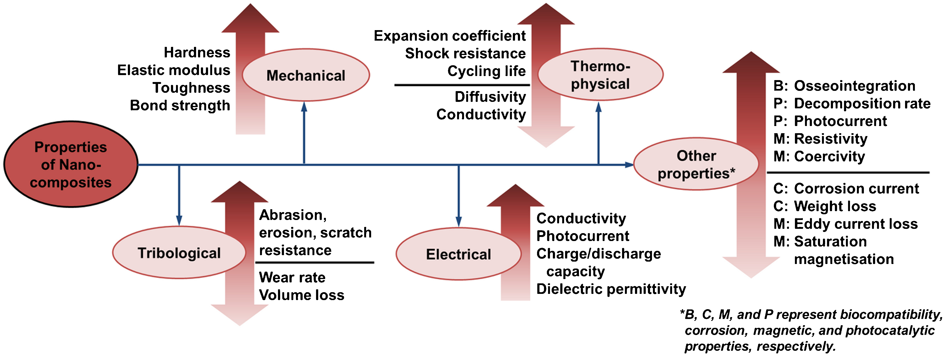
Summary of material properties changes associated with nanocomposite coatings
Mechanical properties
The four main criteria that are often used as measures of the mechanical performance of thermal sprayed coatings are (i) hardness, (ii) elastic modulus, (iii) fracture toughness, and (iv) bond strength. Nanocomposite coatings have generally shown marked improvements in all of these mechanical attributes compared to their conventional, microstructured composite coatings as well as unreinforced, single-phase nanostructured coatings. Nanostructured materials that were reported to benefit in these aspects include (i) carbide or oxide reinforced materials, such as Al2O3–TiO2, Al2O3–ZrO2, ZrO2–Y2O3, WC–Co, B4C–Al, and Cr3C2–NiCr, and (ii) carbon nanotube reinforced matrices, such as hydroxyapatite, Al2O3, and Al–Si. The mechanical properties of several nanocomposite coatings deposited by various thermal spray processes are summarised in Table 12.
Comparisons of the mechanical properties of nanocomposite coatings deposited by various thermal spray techniques
* Indicates the approximate values derived from figures in the respective references.
HVOF: high velocity oxygen fuel; SPS: suspension plasma spray; SPPS: solution precursor plasma spray.
A 20% increase in hardness has been reported in nanostructured Cr3C2–25wt-%(Ni20Cr) coatings deposited by HVOF compared to their conventional counterparts, 265,266 while the hardness of (Al–Mg)–20wt-%B4C nanocomposite coatings was almost double that of unreinforced nanostructured Al–Mg. 134 Cold sprayed nanostructured WC–12wt-%Co. coatings exhibited hardness values between 11·91 and 20·13 GPa, 135,137,200 which is comparable to that of sintered bulk WC–Co. 267 The increase of hardness values is often explained in terms of the reduction of grain size in the nanocomposites. 134
However, bimodal hardness distributions have been observed for nanocomposite coatings deposited by conventional approaches, which exhibit bimodal microstructures, as discussed in the ‘Conventional approaches’ section. Distinctive hardness values were noted in the fully molten and partially molten (nanostructured) regions of the coatings, where the more porous partially molten zones exhibited a lower hardness value compared to the fully molten zones. 120,121 Such behaviour indicates that the microstructure and density of the coatings have more important roles in determining the hardness values than the grain size when there are microstructural variations throughout the coatings.
The reported trend of elastic modulus values for nanocomposite coatings compared to conventional coatings has been inconsistent. While most nanostructured coatings were reported to have a decreased elastic moduli because of increased strain tolerance through irreversible deformation by particle sliding and microcracking, 268,269 others were reported to have an increased modulus. 183,270 Such discrepancies were attributed to the difference in the density and volume fractions of the nanozones in the coatings, as well as a sensitivity of nanostructured coatings to localised measurements and test parameters; e.g. load and indenter geometry.
Plasma sprayed nano-(ZrO2–7wt-%Y2O3) coatings exhibited a more stable, but lower, elastic moduli when exposed to prolonged high temperature conditions compared to conventional coatings, although both coatings demonstrated a significant increase of elastic moduli at the beginning of heat treatment; 268 Fig. 35. The stabilisation of elastic modulus values was induced by the differential sintering behaviour of nanostructured coatings. The high sintering rate of the porous nanozones compared to the fully molten regions led to the opening of large micrometre-sized voids in the coatings, which counteracted the overall densification because of sintering. 119 Such porous nanocomposite coatings, which have low stiffness and are durable through thermal cycling, have been patented as thermal barrier and abradable coatings in applications such as turbine blades and the combustion chambers of aircraft and land-based gas turbines. 271
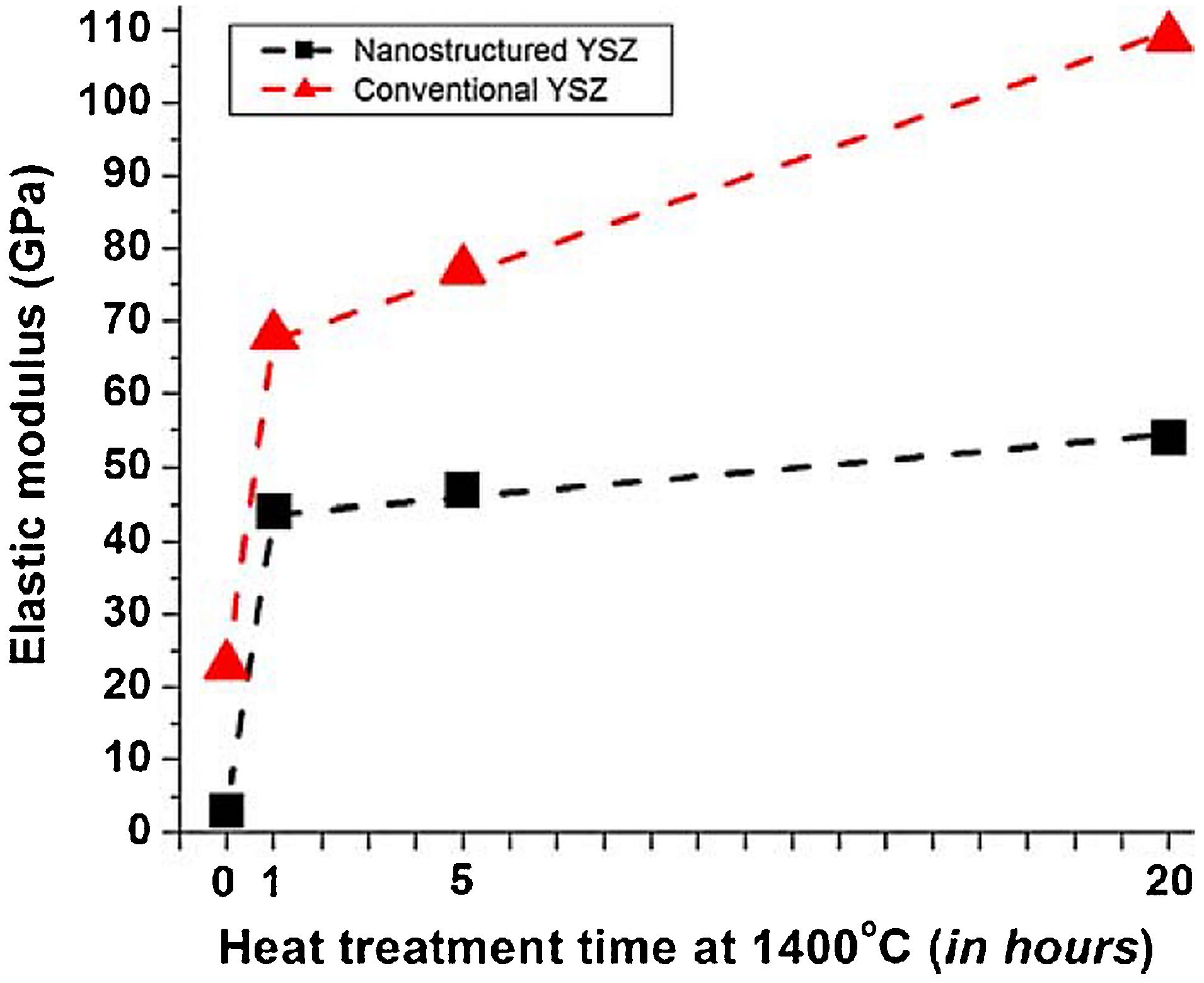
Variations of elastic modulus values of nanostructured and conventional ZrO2–7wt-%Y2O3 coatings when subjected to heat treatment at 1 400°C. Reproduced from Ref. 268 with permission from Springer Science and Business Media
The fracture toughness of plasma sprayed hydroxyapatite coatings was increased by 56% from 0·39±0·09 to 0·61±0·09 MPa m1/2 when reinforced with 4 wt-% of MWCNTs. 234 The improvement of fracture toughness was attributed to the distribution and anchoring of CNTs to form bridge structures, which have excellent elastic recovery and could withstand high bending deformations. Similar effects were observed for MWCNT reinforcements in Al2O3. 272 The CNTs form a web-like structure with the ceramic grains in the nanocomposites, which improve cohesion and inhibit grain growth by restricting grain boundary mobility. 251 However, such cross-linking by CNTs could be damaged by post-deposition heat treatment above 1 200°C that consequently result in total loss or reduced reinforcing effects of CNTs.
Nanostructured Al2O3–13wt-%TiO2 coatings also demonstrated a significant increase in fracture toughness as measured through crack growth resistance and interfacial toughness. 124,173 While the long and well-defined splat boundaries in conventional coatings tend to provide an easy crack propagation path, the periodic disruptions of splat boundaries by the partially molten regions in nanocomposite coatings act to arrest or deflect crack propagation; thereby improving their fracture toughness. Similar crack bridging effects were observed through improvement in the interfacial toughness of Al2O3–13wt-%TiO2 nanocomposite coatings. Improved toughness has also been attributed to enhanced interlamellar strength because of more homogeneous particle distributions. 168
The bond strength of thermal spray coatings is governed by the cohesion strength between splats and adhesion between the coating and substrate. Determination of the cohesion and adhesion of Al–20wt-%B4C coatings through shear testing indicated that the coating adhesion increases in the order: microstructured Al–B4C, unreinforced aluminium alloy and nanostructured Al–B4C. 134 Reinforcement using micrometre-sized ceramic particles reduced the adhesive strength because the ceramic particles caused a decrease of surface area for matrix particle deformation at the coating and/or substrate interfaces. On the contrary, nano-sized B4C ceramic particles were encapsulated within the aluminium alloy matrix, thus minimising the contact area of the ceramic particles at the interface and allowing effective bonding. The contact between splats was also improved in nanostructured coatings because of the refined splat size, resulting in the enhancement of cohesive strength. Similar bond strength improvements were noted through measurements by tensile adhesion tests in nanostructured ZrO2–7wt-%Y2O3, Al2O3–13wt-%TiO2 and WC–12wt-%Co coatings. 123,137,179
Thermal sprayed durable and tough nanocomposite coatings have been implemented in industries such as aerospace, automotive, and marine. Nanostructured Al2O3–13wt-%TiO2 coatings were approved by the United States Navy for shipboard and submarine applications such as arm weldments, bulkhead pivot arms, bearing sleds, front and aft door supports, magnet arms, socket and arm pivot pins, periscope guides, hydraulic pistons, and reduction gear sets. 124,273 Thermal sprayed nanostructured coatings with enhanced mechanical properties, such as ZrO2–7wt-%Y2O3 and (ZrO2–7wt-%Y2O3)–Al2O3, are widely used as durable thermal barrier coatings for gas turbine engines in aircraft and power generation plants. 274–276
Nanocomposite coatings with high hardness and fracture toughness incorporating 3–5 nm carbide or oxide grains embedded in an amorphous matrix have also been developed for aircraft components. 277 The coatings capitalise on the macroscopic ductility mechanism that is unique to nanocrystalline–amorphous composites through the large proportion of 1–2 nm nanograins in the amorphous matrix. Mechanically hard coatings containing dispersed nano-sized carbide particles, such as SiC, TiC, WC, or VC, have been patented as hard protective coatings for internal combustion engine components such as piston rings. 278 Hard nanocomposite coatings are also advantageous as wear resistant coatings, which will be discussed in the next section.
Tribological properties
There is a general trend reported in the literature that the wear resistance of a material is directly related to its hardness and toughness; i.e. wear resistance is increased when hardness and/or toughness increased. 121,174,184 Such effects were evidenced in thermal sprayed nanocomposite coatings, where the enhanced wear resistance pertains to (i) the crack arrest and deflection by nanozones, 124 and (ii) the enhanced interlamellar strength from homogeneous particle mixing. 168 Depending on the wear mechanisms and the coating characteristics, the coating hardness and toughness influence the wear resistance to different extents. For instance, suspension plasma sprayed Al2O3–40wt-%ZrO2 coatings exhibited a higher abrasion resistance compared to that deposited by HVOF owing to its superior hardness. 158 However, the brittle nature of the plasma sprayed coatings has resulted in poor erosion resistance compared to HVOF coatings, which have high crack propagation resistance and toughness compared to plasma sprayed coatings.
Nanostructured ZrO2–7wt-%Y2O3 = coatings have shown a 20% reduction in wear rate compared to its conventional counterpart, although there has been no significant changes to the coefficient of friction. 270 In addition to the phase transformation toughening by stress-induced martensitic transformation of ZrO2 from tetragonal to monoclinic, the enhanced wear resistance was also attributed to the narrowing of the defect size distribution, which led to the improvement of resistance to crack propagation. Incorporation of 4 wt-% CNTs reduced the wear volume loss of hydroxyapatite coatings by almost 50%. 235 The CNTs act as reinforcing and self-lubricating elements in the coatings, while improving the fracture toughness of the coatings through anchoring effects and energy absorption from protruding CNTs at the surface during abrasion.
The abrasion resistance of Al2O3–13wt-%TiO2 coatings was improved eight-fold by using a nanostructured feedstock, compared to conventional coatings. 167 The dense and finely dispersed nanozones, which were acquired through penetration of the semi-molten porous core by molten material during in-flight, contributed to the increased crack propagation resistance and wear resistance of the coatings. The wear mechanisms in conventional Al2O3–13wt-%TiO2 coatings were identified to be grain dislodgement because of grain boundary fracture and lateral crack chipping, while wear in nanostructured coatings was only through grain dislodgement. 170 Wear resistance of Al2O3–13wt-%TiO2 coatings can be further improved by three-fold through the addition of CeO2 and ZrO2 particles; 170,279 Fig. 36. Similarly, the addition of 50wt-% Fe3O4 as a solid lubricant in Al2O3–13wt-%TiO2 coatings significantly reduced the coefficient of friction, which result in a four-fold increase in the sliding wear resistance and a three- to five-fold increase in the abrasive wear resistance. 280 Such self-lubricating wear resistant coatings find application in high pressure fuel pumps for direct injection engines that use cleaner, lubricant-free fuels.
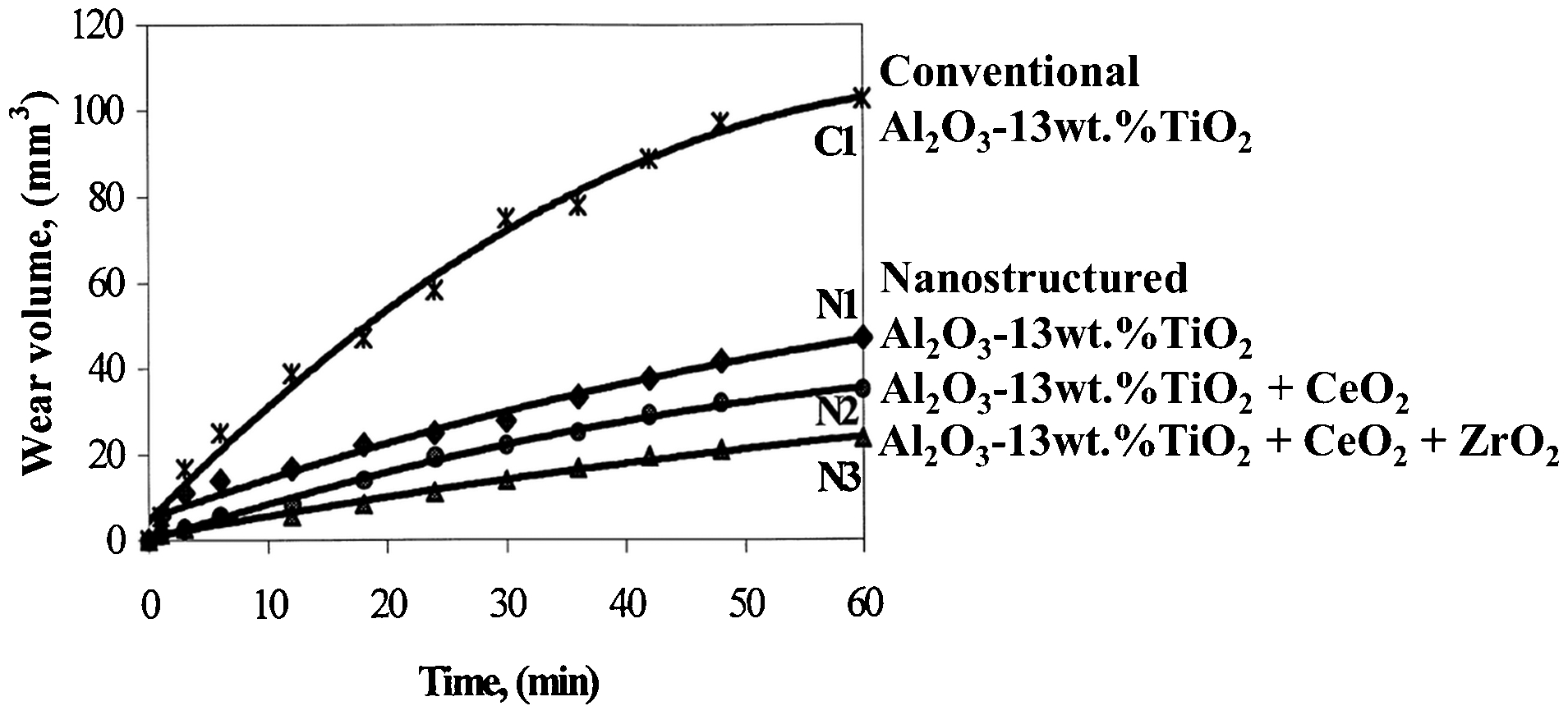
Wear volumes of conventional and nanostructured plasma sprayed Al2O3–13wt-%TiO2 coatings. Reproduced from Wang et al. 170 with permission from Elsevier
On the contrary, the abrasive wear resistance of nanostructured WC–Co coatings was found to be inferior to that of conventional coatings. 201,203 The wear rates of HVOF sprayed nanostructured WC–Co were between 1·4 and 3·1 times higher than coatings deposited using conventional powders. The deterioration of wear resistance was attributed to WC pullouts and decomposition. The wear mechanism of WC–Co coatings is through binder phase removal by abrasive particles. Therefore, larger carbide particles in conventional coatings are more resistant to wear because the binder phase must be removed to a greater depth before the particle can be removed. 203
On the other hand, the fine carbide particles in nanostructured coatings can be detached with the removal of only a small amount of binder, and the fine WC pullouts contribute to further abrasion. The nano-sized particles are also more susceptible to in-flight decomposition compared to conventional particles, which led to the decrease of the wear resistant WC phase and the formation of brittle amorphous binder phases in the coatings. 201 Implementation of a multimodal feedstock consisting of a mixture of nano- and sub-micrometre-sized particles rather than a fully nanostructured feedstock improved the wear resistance of WC–Co coatings by over 30% compared to conventional coatings because of better retainment of WC particles. 281–283 Such multimodal coatings have been patented as abrasion wear resistant coatings. 284
The erosive wear resistance of Al2O3–20wt-%(ZrO2–8Y2O3) coatings was increased by about 50% through the addition of 10% nano-SiC particles. 184 The SiC hard phase contributed to an increase of hardness and fracture toughness of the coatings, thereby improving the erosion resistance. Similar improvement in scratch resistance and sliding wear resistance was observed in polycarbonate and Nylon-11 coatings through SiC and/or carbon black nanoparticle reinforcement. 46,260,262,263 Coatings that incorporate modified hydrophobic ceramic reinforcing particles exhibited the best scratch and wear resistance because of enhanced polymer-ceramic adhesion and reduced agglomeration of the reinforcement particles. 46,263 The scratch resistance increased as a function of decreasing reinforcement size 263 and increasing polymer particle size. 262
Hard and tough nanocomposite coatings can be used as wear resistant coatings for structural applications in a variety of industries. Wear resistant nanocomposite coatings can potentially increase component life up to five times. 37,285 Self-lubricated, thermal sprayed nanocomposite coatings comprising a BN or Fe3O4 lubricant phase, a hard ceramic phase, and a ductile metal phase have been patented as low friction and wear resistant coatings for metal machinery. 286,287 Thermal sprayed coatings containing nano-Cr2O3 and a secondary oxide or carbide immiscible phase are used as erosion and abrasion resistant coatings to enhance the durability of valve components. 288 Polymer coating systems consisting of solid lubricants such as high density polyethylene, polytetrafluoroethylene, graphite, or molybdenum disulphide, which are deposited by spray coating, dip coating, pulsed laser deposition, CVD, or electrochemical deposition, can potentially be adapted for thermal spray deposition and used as protective coatings on threaded joints for metallic pipes. 289
While dense nanocomposite coatings are widely used as wear resistant coatings, porous nanocomposite coatings with a friable structure are used as abradable coatings. Porous nanocomposite coatings are produced by retaining the porous nature of the nanostructured feedstock through incomplete infiltration of the non-molten particle core by the semi-molten region. 271 Abradable coatings are typically porous composites that consist of a metal phase and a self-lubricating non-metal phase. Such coatings are particularly useful as abradable seals to reduce the gas path clearance in gas turbine engines and improve the efficiency and fuel consumption of aircraft and power plants. 79 These coatings must be abradable yet mechanically stable to withstand high temperature operating conditions. Therefore, abradable coatings are often associated with low thermal conductivity thermal barrier coatings, which will be discussed in the next section.
Thermophysical properties
Heat conduction in solids occurs mainly through lattice waves; i.e. elastic or ultrasonic waves through phonon propagation. Heat conduction by lattice waves is influenced by the lattice defects, grain boundaries, and extended imperfections, which collectively determine the mean free path or attenuation length of the heat carriers. 290 However, at elevated temperature, the radiative component becomes a significant mode of heat conduction in addition to lattice waves. Heat transfer through radiation can be reduced by porosity or inclusions with a substantially different index of refraction than the radiating body. Therefore, the optimised microstructure for thermal conductivity reduction is a matrix of nanometre-sized grains with relatively large pores or other stable inclusions of about 0·5 μm diameter. 290
Comparing nanostructured thermal spray coatings to their conventional counterparts, nanostructured coatings exhibit a lower thermal conductivity and diffusivity because of their small grain size and homogeneous pore distributions. 291,292 The attenuation length decreased when the grain size decreased, hence effectively reducing grain boundary scattering and thermal conductivity; 290 Fig. 37a . The smaller and more homogeneously distributed pores and thinner splats in nanostructured coatings provided a larger boundary volume for effective phonon scattering and stronger interfacial thermal resistance, which consequently reduced the thermal conductivity. 292 The equiaxed grains in nanostructured coatings with tortuous zigzag-like boundaries also contributed to a greater thermal resistance compared to conventional coatings, which exhibit columnar grains that are aligned parallel to the direction of heat flow. 292
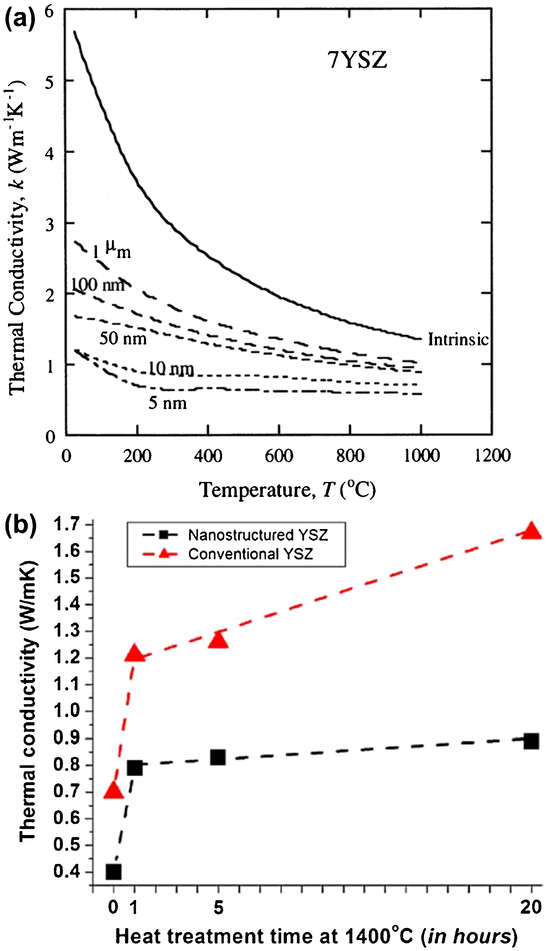
a Theoretical thermal conductivity of ZrO2–7wt-%Y2O3 coatings as a function of temperature and grain diameter (reproduced from Klemens and Gell 290 with permission from Elsevier) and b evolution of thermal conductivity values of ZrO2–7wt-%Y2O3 coatings during sintering at 1 400°C (reproduced from Lima and Marple 268 with permission from Springer Science and Business Media)
The thermal conductivity of plasma sprayed conventional ZrO2–7wt-%Y2O3 coatings was reported to be almost twice that of nanostructured coatings. 268 A similar reduction of thermal diffusivity was observed for nanostructured ZrO2–7wt-%Y2O3, 119,291 and Al2O3–50wt-%ZrO2 coatings, 293 indicating that the coating density is not the determining factor for the decrease in thermal conductivity. Such effects are the result of effective phonon scattering and interfacial thermal resistance associated with the decrease of grain size and splat thickness. The influence of interfacial thermal resistance on thermal conductivity is evidenced by the decrease of thermal conductivity through deposition of thin, multi-layer coatings. 294,295 The thermal expansion coefficient of nanostructured ZrO2–7wt-%Y2O3 coatings was also found to be higher than that of conventional coatings. 291
Exposure to high temperature resulted in a substantial increase in thermal conductivity for both conventional and nanostructured coatings. 119,268 The increase in thermal conductivity is attributed to sintering effects, where the pores were healed and the contact between splats improved. However, the thermal conductivity growth rate for conventional coatings was almost five times higher than that of nanostructured coatings; 268 Fig. 37b . Such differences in the thermal conductivity growth rate are attributed to the differential sintering behaviour of nanostructured coatings as discussed in the ‘Mechanical properties’ section. The stable thermal conductivity of nanostructured coatings at elevated temperature places them as a viable candidate for high temperature applications.
Suspension plasma sprayed Al2O3–40wt-%ZrO2 coatings exhibited a higher thermal conductivity compared to coatings deposited by plasma spraying of agglomerated feedstock. 158 The high thermal conductivity was attributed to low interfacial thermal resistance because of the more intimate splat contact and low porosity in SPS coatings. The improved bonding, in addition to increased strain tolerance, contributed to a longer thermal cycling life of SPS and SPPS coatings. 179,181 On the other hand, the coatings deposited by suspension HVOF spray exhibited a lower thermal conductivity than its plasma sprayed counterpart because of a high amorphous phase content and limited particle bonding because of poor melting in the low temperature flame. 158
The thermal cycling life of nanostructured ZrO2–7wt-%Y2O3 coatings was 2–4 times higher than that of conventional coatings. 296,297 Nanostructured coatings exhibited significantly different thermal shock behaviour than conventional coatings, where crack propagation in nanostructured coatings occurred through intergranular fracture while that in a conventional coating was through intergranular and transgranular fracture. 296 The increase of crack path tortuosity through intergranular fracture enhanced the thermal shock resistance of nanostructured coatings. During thermal cycling of nanostructured coatings, vertical cracks propagated from the surface towards the bond coat without any horizontal propagation at the coating interface because of the presence of nanozones. 296 Such vertical cracks were not found in conventional coatings and were replaced instead by horizontal cracks near the coating interface.
The use of low thermal conductivity nanocomposite coatings as advanced thermal barrier coatings can potentially improve the thrust and lower the fuel consumption of gas turbine engines. The thermal barrier coatings provide an additional layer of insulation to engine components such as turbine vanes and combustors. An example of such a nanocomposite coating is given in Ref. 298. A thermal barrier system that consists of two layers of ZrO2–7wt-%Y2O3 coating with a nanostructured inner layer was claimed to improve the ductility of thermal barrier coatings. 275 Nanocomposite coatings with high thermal stability can also be used as abradable coatings to minimise clearance in high temperature applications.
The temperature distribution in a thermal barrier system is depicted in Fig. 38. Such nanocomposite coatings essentially exhibit vertical cracks, 276 and/or a porous nanostructure, 271 which maintains the low conductivity and stabilises the thermal diffusivity after several hours of thermal exposure. An intermediate coating between a bond coat and a ceramic top coat, which consists of NiCoCrAlY and Al2O3 nanoparticles, has been implemented to reduce thermal stresses that arose from different thermal expansion coefficients between the bond coat and top coat. 299
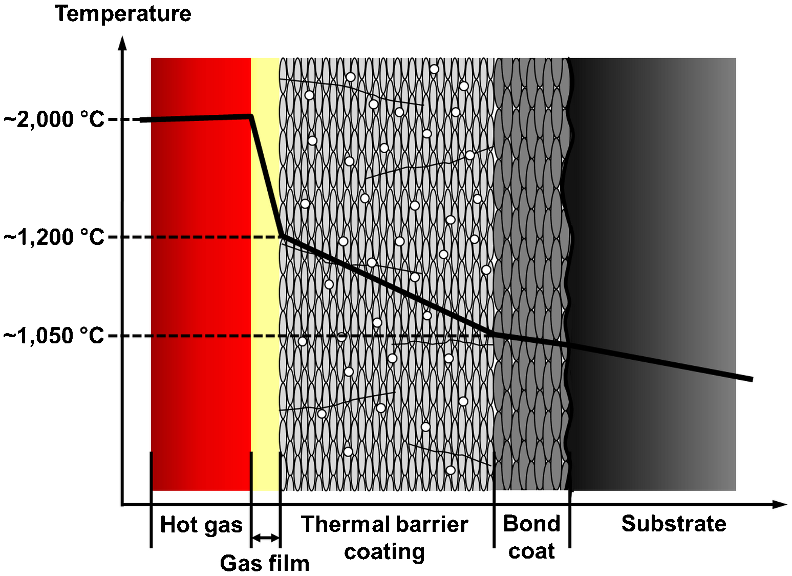
Schematic of temperature distribution across thermal barrier system
Electrical properties
The electrical properties of nanocomposites have been widely capitalised, either for their conductivity 300 or insulation, 19 in applications such as electronics, 31 energy conversion and storage, 33 and tissue engineering. 301 However, reports on the electrical properties of thermal sprayed nanocomposite coatings have been scarce. The literature for these coatings has been more focused on the coating microstructure rather than presenting evidence of their electrical properties.
Suspension plasma spray has been presented as a potential solution for producing a bilayer anode–electrode nanocomposite system for SOFC applications. 302 The bilayer system consists of a porous Ni–(ZrO2–8wt-%Y2O3) layer for the anode and a dense ZrO2–8wt-%Y2O3 layer as the electrolyte. The different microstructures were attained by manipulating the in-flight droplet's surface tension and viscosity through the use of different solvents; i.e. water suspensions to produce a dense microstructure and alcoholic suspensions for the porous microstructure. A functionally graded TiO2–hydroxyapatite nanocomposite coating has also been deposited by SPS to improve the interfacial bond between hydroxyapatite and the implant material. 238,239 The electrical conductivity of TiO2, which has been measured in bulk materials, 303 and nanostructured coatings, 304–306 could potentially be used to direct cell growth in biomedical implants. 301 However, this approach has yet to be verified because of a paucity of experimental data.
Nanostructured dielectric coatings for applications in low frequency electrical components and as insulation layers in embedded three-dimensional circuitry have also been developed via thermal spray. 307 Nanocomposite Al2O3–13wt-%TiO2 and Al2O3–5vol.-%Ni coatings were found to have increased electrical permittivity compared to pure nano-Al2O3 coatings; while the incorporation of nano-NiO, SiO2 and glass were found to have decreased the permittivity. The varying effects of the different materials on permittivity were related to the presence of porosity, extent of α-Al2O3 phase retainment and the surface roughness of the coatings. Conductive nanocomposite coatings have also been developed in the same study, where the incorporation of 5 wt-% of nano-WC doubled the electrical conductivity of pure copper because of the suppression of oxide formation. 307
Similarly, the electrical conductivity of silicon carbide, SiC, coatings, which are widely used as functional coatings in electronic and opto-electronic devices, was improved by the incorporation of nano-sized titanium nitride, TiN. 131 Silicon carbide–titanium nitride nanocomposite coatings deposited by cold spray were composed of a partially agglomerated SiC insulating phase because of their high surface area and surface energy. The conductive TiN phase in this nanocomposite coating was homogeneously distributed to form a net-like structure that contributed to the electron transport properties of the coatings. 131 The electrical resistivity of the coatings was decreased with the increase of conductive TiN contents.
A nanocomposite system integrating a photoelectric conversion function and electron storage function into a single device, which could potentially be used for photo-cathodic corrosion protection and solar energy conversion and storage, was produced by thermal spraying TiO2–50wt-%Fe2O3 coatings. 308 The reduction of TiO2 particle size to nanoscale has enhanced the photocurrent of the coatings by more than 10 times. Such enhancement was attributed to the increase of the particle surface area and quantum size effect. On the other hand, the use of nano-Fe2O3 doubled the charge and discharge capacity of the coatings, which contributed to the improvement of the electron storage function. The enhancement of electron storage capacity was associated with the increase in reaction rate from the larger surface area of nano-Fe2O3.
Plasma spray was used to create metastable ceramic phases for SOFC applications through rapid quenching. 309 The fuel cell components consist of three nanostructured plasma sprayed layers: (i) nanoporous lanthanum strontium magnesium, La1−xSrxMnO3, as a nanoceramic cathode; (ii) dense metastable YSZ, ZrO2–8wt-%Y2O3, as the electrolyte; and (iii) porous Cu/Ni–(ZrO2–8wt-%Y2O3) nanocomposite as the anode. Porosity was introduced into the anode and cathode layers to enhance the catalytic activities at the electrodes. The plasma sprayed nanocomposite SOFC reduced the operating temperature from 800 to 600°C by increasing the rate of electrochemical reactions through enhanced catalytic activity and faster transport of negative ions. Nano-gas channels and porosity were introduced to the SOFC's nanocomposite anode by plasma spray to further enhance the electrochemical activity and retard nickel aggregation under the high temperature environment. 310 The conductivity of Ni–(ZrO2–8wt-%Y2O3) nanocomposite manufactured by plasma spray compared to its conventional microstructured counterpart is depicted in Fig. 39. Nanostructured samarium doped ceria deposited by SPS was also proposed as an alternative SOFC electrolyte material for a low operating temperature environment. 274
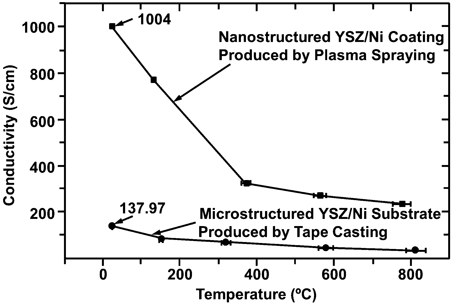
Conductivity of (ZrO2–8wt-%Y2O3)–Ni nanocomposite anode as a function of temperature, compared to that of conventional microstructured anode fabricated by tape casting 310
Nanocomposite semiconductor materials were also developed by thermal spray for opto-electronic applications. 311 The coating is composed of a polymorphic matrix, such as silicon or germanium doped derivatives, with dispersed metastable nanocrystals formed during the thermal spray process. Nano-fillers such as CNTs are also known to produce composites with enhanced electrical properties. 19,31,215 Despite many studies on thermal sprayed carbon nanotube composites, the potential of these composites in relation to their electrical properties is yet to be explored.
Other properties
Biocompatibility and cytotoxicity
As discussed in the ‘Mechanical properties’ section, nanocomposites have superior mechanical properties compared to their conventional counterparts. Nanostructured materials such as titania, 236,240 zirconia, 237 and carbon nanotubes 234,235 have been used as biocompatible reinforcements to impart strength and toughness, and to improve the adhesion of hydroxyapatite coatings for biomedical applications. Such nanostructured biomedical coatings consisting of a mixture of fully and partially molten particles have been patented for implants such as artificial hip joints, artificial knee joints, and artificial teeth. 312 Another approach used to improve the adhesion of thermal sprayed hydroxyapatite to implant materials uses feedstock particles that were coated with titanium by using a vapour deposition process. 313 Substantial anti-bacterial properties can also be imparted to such nanocomposite coatings by doping with small amount of known anti-bacterial element such as silver. 231
Nanostructured materials also exhibited enhanced biocompatibility with osteoblast cells and osseointegration compared to their conventional counterparts because of the effects of nanoscale roughness on surface wettability and cell adhesion. 232 However, the cytotoxicity of nanomaterials in vivo is still a subject of constant debate. While there were indications that nanomaterials nurture cell proliferation through enhanced precipitation and mineralisation, 87,234,251 there were also evidence of adverse biological effects. 301,314
Thermal spray nanocomposite coatings intended for biomedical applications have not been reported to be toxic thus far. However, most studies have focused on the effects on cell adhesion and proliferation rather than direct evaluation of cytotoxicity. Although both aspects are usually interrelated, improved cell growth does not necessarily represent non-toxicity, rather there are other factors involved; e.g. surface topography vs. surface chemistry. There is still a lack of understanding on the biocompatibility and toxicology of such coatings in vivo.
For instance, CNT-reinforced hydroxyapatite coatings are receiving considerable attention in this regard. On the one hand, in vivo studies have indicated the coatings to be non-toxic, as evidenced by good spreading and unrestricted osteoblast cell growth along surfaces in contact with CNTs. 234 The CNT-reinforced hydroxyapatite coatings, as well, exhibit a greater total number of cells compared to pure hydroxyapatite coatings. 251 On the other hand, CNTs by themselves have been reported to cause biological effects ranging from inducing intracellular reactive oxygen species 315 to impairing phagocytosis with attending cell necrosis and degeneration. 314,316
Such contradicting outcomes are likely to arise because the role of CNT characteristics is often overlooked in most studies. Characteristics such as the compositional purity, concentration (dose), as well as the degree and type of dispersion are all critical to the cytotoxicity of CNTs. Pulskamp et al. 315 demonstrated that commercial CNTs induce the formation of intracellular reactive oxygen species and decrease the mitochondrial membrane potential, both of which are dose- and time-dependent. The same test on purified CNTs did not reveal any of these biological effects, indicating that the trace metals in commercial CNTs are liable for such effects.
Using CNTs with comparable amount of impurities, Wick et al. 317 further established that the type of agglomeration, and consequently the degree of CNT dispersion, significantly affects the cell activity and proliferation in a dose-dependent way. At the same concentration, dispersed and agglomerated CNTs were established to be less and more cytotoxic than asbestos, respectively. The difference in cytotoxic effects of both types of CNTs arose from the change in structural characteristics of the CNTs. Agglomerated CNTs, which are bigger, stiffer, and more solid than dispersed CNTs, exhibit similar characteristics and cytotoxic response to asbestos. 317 With further knowledge and understanding on the influence of the nanomaterial characteristics on biological effects, it will be possible to mitigate their toxicity by developing new approaches for their incorporation.
Corrosion resistance
Corrosion resistant coatings are widely used as protective coatings for components subjected to high temperature oxidation or an aqueous corrosive environment. Protective coatings used in high temperature environments are also known as ‘thermal oxidative barrier coatings’ because they function as both thermal barrier and corrosion resistant coatings. These coatings are used commercially for industrial boilers and aerospace components such as turbine engine blades or vanes, the leading edges of airfoils, combustor chambers or liners, seals and joints. The corrosion resistance of steel, measured through the decrease of corrosion current and weight loss in electrochemical tests, was improved by two times through the application of a NiCr coating incorporating nano-sized SiO2, Cr2O3 and/or Al2O3 particles. 318 The dense nanocomposite coating was deposited by a single step deposition process using a combination of HVOF and arc spray, where the nanoparticles were synthesised in-flight by HVOF from liquid precursors while the metallic matrix alloy was fused by arc spray. Such high density coatings can be used in applications such as coal fired boilers to restrict the migration of corrosive solution or molten material to the substrate interface.
A low oxygen permeability bond coat consisting of a layer of thermally grown α-Al2O3 on HVOF nanostructured NiCrAlY with oxide, nitride and/or oxynitride inclusions has been patented for thermal barrier applications. 319 Ceramic nanocomposite coatings that consist of Si3N4, BN, SiC and/or B4C with an oxide forming metal are also being used as thermal oxidative barrier coatings for applications in severe high temperature, corrosive, and oxidising environments. 298 The corrosion resistance of nanostructured WC–Co wear resistant coatings for application in a corrosive aqueous environment was improved by 350% compared to its conventional counterparts, where the nanostructured coatings withstood 600 h without any signs of pitting corrosion while conventional coatings failed after 130 h in a similar salt fog spray test. 281 Corrosion resistant coatings containing nano-sized chromia particles and a secondary immiscible phase such as ZrO2, Ta2O5, B4C, SiC, TiC, Cr3C2, or WC, have been used for valve components in an acid leaching environment. 288 Nano-sized corrosion inhibiting agents such as zinc calcium strontium orthophosphate silicate hydrate compounds can be incorporated into coatings for corrosion protection in threaded connections; e.g. threaded joints in metal pipes. 289 Nanocomposite FeNbCrW coatings are also applied by electric arc spray to improve the corrosion resistance of steel in the naval industry. 320
Photocatalytic properties
Titania, TiO2, is known for its photocatalytic properties, 321,322 and is widely employed in applications such as self-cleaning surfaces, water and air purification, cancer therapy, self-sterilising surfaces, and photosensitisation. 323 As with other catalysis processes, photocatalytic performance is enhanced when there is a greater surface area; i.e. smaller particle size, to promote the reaction rate. 324 Nanostructured TiO2 coatings deposited by thermal spray exhibited significant improvements in their photocatalytic performance compared to their conventional counterparts. 325 Photocatalytic performance of coatings is typically measured by the rate of pollutant degradation for applications involving organic pollutants removal, 324,326 or by the photocurrent density for photovoltaic applications. 327
Various studies have established that anatase-TiO2 demonstrates improved photocatalytic performance compared to the rutile phase, although the anatase tends to transform to rutile during the thermal spray process. 324,328–330 Doping with oxides of group V elements, such as Nb and Ta, has been proven to inhibit the thermally activated transformation of anatase to the rutile phase, thus exhibiting improved photocatalytic performance that exceeded that of the standard Degussa P-25 coating. 326 Similar enhancement in photocatalytic activity was observed in nanostructured TiO2–Al coatings. 331 Suspension and SPPS are also more favoured as the deposition method of nano-TiO2 for high anatase phase retainment compared to conventional approaches. 329,330
Nano-TiO2 particulates synthesised through SPPS were incorporated into silicon coatings to accelerate photoreactions and increase the photovoltaic efficiency. 332 Such an approach of depositing nanostructured TiO2 coatings via suspension or SPPS have been patented for the fabrication of photovoltaic cells. 274 Porosity was introduced into nano-TiO2 coatings through the addition of polyethylene glycol to increase the surface area of the nanostructured coating and to improve the transfer of ions through electrolytes, contributing to an increase of short-circuit current density and conversion efficiency of dye-sensitised solar cells. 327 Nano-TiO2 particles have also been incorporated into hydroxyapatite to create nanocomposite or multi-layered coatings, 239,240 which could impart anti-microbial properties to surfaces because of the ability of hydroxyapatite to adsorb contaminants and the capacity of TiO2 to decompose bacteria and other contaminants. 333
Magnetic properties
Reports on nanostructured magnetic coatings deposited by thermal spray have been scarce and are mainly centred on yttrium iron garnet, Y3Fe5O12 (YIG). Nanostructured YIG coatings have been formed by SPPS through different reaction paths, both with and without an intermediate yttrium iron perovskite, YFeO3 phase. 334 The annealed YIG coatings exhibited saturation magnetisation and coercivity values that are comparable to those of bulk YIG. Aluminium-substituted YIG (YAG) coatings deposited by a similar process exhibited a single phase microstructure rather than the two phase microstructure observed in YIG. 335 However, the saturation magnetisation and coercivity of YIG coatings decreased significantly with Al-substitution.
The eddy current frequency range in plasma sprayed soft magnetic Fe76P11−xSixC8B5 coatings for use as inductive components was improved by increasing the electrical resistivity of the coatings through the addition of 20 vol.-% ZrO2. 336 The frequency limit of the nanocomposite coatings was shifted to above 1 MHz, where the electrical resistivity was improved by 50%, but the saturation magnetisation of the coatings deteriorated by 20% from 1 to 0·8 T. 336 Thermally sprayed soft magnetic nanocomposite coatings containing an insulating phase has been patented for similar purposes. 337 This three-component nanocomposite coating comprises a magnetic core particle that is coated by an insulating phase and embedded in a magnetic or insulating matrix phase; 337 e.g. nano-Co/SiO2. The interaction of neighbouring magnetic nanoparticles maintains the desired soft magnetic properties, while the insulating phase provides high resistivity to reduce the eddy current loss and core loss of the material.
Concluding remarks: challenges and looking to the future
Feedstocks
The thermal spray process can be segmented into five distinct groupings as indicated in Fig. 40. The presented sequence from 1 to 5 is intended to be logical; i.e. the thermal spray process starts with an appropriate feedstock and finishes with testing and evaluation for quality control purposes before being implemented towards specific applications as indicated in box 6.
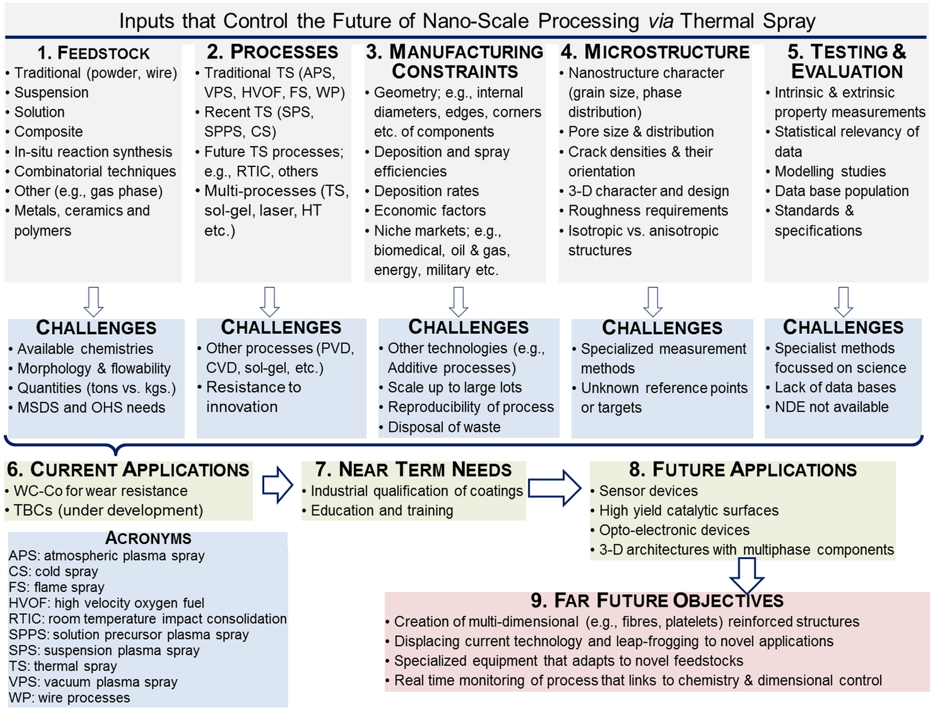
Input criteria that determine the outcomes for nanoscale materials manufactured by thermal spray methods
Nanostructured coatings exist in some microstructural form for the majority of thermal spray coatings perforce of the rapid solidification process. 52,338 Thus, microstructural artefacts; e.g. splat sizes, porosity, cracks, phase distributions and grain sizes are likely to form. However, the future outlook demands such features to be dominant and manufactured in a controlled fashion rather than be a curious and scientifically interesting anomaly. The most appropriate feedstock is consolidated from nano-particulates that are produced via a chemical route. The art in the thermal spray processing is to adjust the spray parameters so that only partial melting arises in order to maintain nanostructures that are consolidated into an integral coating by partial melted particles. 75,79,103
The SPS and SPPS methods show considerable promise in lowering the feedstock cost barrier and achieving nanostructured deposits; however, there are associated challenges with regard to attaining high deposition efficiencies and high rates of deposition; 104,105,339 characteristics that are both vital for manufacturing environments. It is foreseen that specific applications, possibly in the thermal barrier coatings or electronic devices sectors, will be primary drivers to grow these methods.
The principal challenge in the area of feedstock is to attain nanostructured deposits, therefore, future developments will, most probably, involve a combination of conventional and solution/suspension materials. Thus, it is suggested that (i) duel injection port strategies and (ii) use of a single injection port, but slurry feedstock consisting of traditional solid and low viscosity mixtures, will pave the way for increased production routes.
Associated with these industrial needs are those of (i) an ability to scale up feedstock production and ensuring their long storage capability, especially if any fluid components are present, and (ii) safe guards and controls with respect to occupational health and safety. The issue of cost will always be present and scale-up in specific niche areas, which are suggested above, will drive cost down.
Processes and manufacturing
The traditional and recent thermal spray processes in box 2 of Fig. 40 have been deployed successfully to manufacture nanostructured materials. The main issue, though, boils down to manufacturing constraints that arise under these well-known processes. Thus, these processes are line-of-sight, exhibit relatively low deposition and spray efficiencies, and are inflexible with regard to the spray footprint that controls the deposit resolution. 52 These factors are all adverse to the manufacturer economics that drives innovation.
The promise of nanoscale processing via thermal spray is that there may be an opportunity to break down the barriers, also described as ‘challenges’, posed in Fig. 40; especially by employing multiple processes. For example, sol-gel infiltration 340 of an existing conventional thermal spray coating via dipping or simple aerosol spray methods that is followed by a post-process such as (i) arc plasma heating (with or without the thermal spray device), 341 (ii) conventional furnace heat treatment, 342,343 or (iii) laser glazing. 344 As well, there is a large market for near-net shape manufacturing processes; therefore, additive manufacturing by means of thermal spray deposition is a distinct opportunity.
It is recognised that there is resistance to changes in any engineering practice. Thus, the technical and financial advantages need to be articulated clearly before the adoption of such practices.
The microstructure
The microstructure is driven by the need for certain intrinsic and extrinsic needs. The prior knowledge for thermal spray coatings indicates that the physical characteristics are determined by the extrinsic characteristics. That is, the physical properties depend strongly on the defective microstructure; 345 which accounts for their highly variable nature.
The opportunity to manufacture nanostructured coatings offers potential to enhance physical attributes such as modulus, ductility, thermal conductivity, and magnetic and electrical properties. Such properties may be tailored by adjusting the microstructure. For instance some strategies include (i) modifying the feedstock with regard to chemistry and intrinsic size, 346 (ii) varying the thermal spray process so that the feedstock experiences appropriate thermal and velocity conditions to achieve the desired microstructure, 199 and (iii) using other manufacturing techniques, such as sol-gel infiltration, 340 laser post-processing, 203 and sintering techniques, 268,341 to modify the as-received thermal spray coating.
The overall notion is to re-design the engineered coating on the basis of the desirable microstructure, rather than being constrained by conventional feedstocks and processes. Therefore, the microstructure is transformed into being the prime design criteria and not a fortuitous accident that derives from the manufacturing process.
Testing and evaluation
Testing of nanostructured materials is well-developed. For example, mechanical properties may be determined by nano-indentation 347,348 and scratch techniques; 184,263 phase structure by means of XRD, 122,123 Raman spectroscopy, 326 transmission and scanning electron microscopy; 217,237 and roughness via atomic force microscopy. 349,350 These methods can be classified as ‘conventional and routine’ techniques.
The nature of all test methodologies on thermal spray deposits is contingent on the understanding that the property measure is extrinsic in nature. Therefore, the measured values are highly variable because of the inhomogeneous structure of these coatings. The exceptions to this understanding would incorporate processes that create dense coatings because these lamellar microstructures are typically disrupted. The extrinsic nature of coatings implies that properties, atypical of the original materials, can be realised and herein lies technical opportunities. Thus, the design engineer is no longer constrained by text book values for material properties because these are regulated by the thermal spray nanostructure. Furthermore, the statistical variability of the nanostructure will be related to the phase distribution; thereby leading to known property distributions.
Applications in the future
The current (2014) global thermal spray industry for the domestic market is valued at about 7·1 B. 351 The market for these traditional applications of thermal spray coatings include 52,53 (i) transportation systems such as aerospace, automotive, naval and railway networks; (ii) heavy industry such as remanufacturing for dimension restoration, and rolls in the steel, papermaking, and printing industries; (iii) prostheses for the bioengineering market; and (iv) the energy producing sectors such as land-based turbines, geothermal sources, wind energy, and solid oxide fuel cells. These markets will expand with the use of appropriate nanoscaled structures because of the improved performance gains that evolve from the nanostructure.
The more critical growth markets for the future are those that will be uncovered because of the new materials and thermal spray processes that will be discovered. Extension of cold spray methods to the application of nanostructured ceramics and cermet composites would open up opportunities for advanced applications where wear control is an issue. In an alike fashion, SPS and SPPS methods are on the cusp of being of industrial importance and any shift to creating nanostructures will accelerate their commercial adoption.
Boxes 6–9 allude to the need to create new market sectors that are outside the traditional applications for thermal spray deposits. It is especially important to identify future markets such as (i) sensor arrays, (ii) opto-electronic devices, (iii) nanostructured coatings for energy harvesting, (iv) thin coatings as masking materials for thin film technologies such as PVD and CVD, and (v) nanostructured biomimetic materials. These markets are currently being explored with regard to thermal spray technologies and bode well for a healthy future.
Footnotes
Acknowledgements and Dedication
The authors acknowledge the financial support provided from a Swinburne University Postgraduate Research Award (SUPRA). The authors dedicate this review to the memory of Professor Joachim “Jockel” V.R. Heberlein; born 19 August 1939 and who passed away on 17 February 2014. Jockel made significant contributions in the topical area of nanomaterials that were manufactured via thermal plasma techniques. “His lively spirit, intense interest, and amazing energy all left him. … I wonder where they all went.”�