
Abstract
Dye sensitised solar cells (DSCs) have been assembled directly onto a prepainted construction steel substrate. This has been achieved by chemically isolating the underlying substrate through the application of a high temperature resistant organic polymer rendered conducting by applying a 1·2 μm collection electrode of magnetron sputtered titanium. The resultant DSCs achieved 2·9% energy conversion efficiency under one sun illumination compared to 3·2% for identical cells manufactured on 1 mm thick Ti coupons. The slight reduction in efficiency reflects the increasing resistance of the substrate 1·2 μm Ti layer, which results from microcracking during the titania sintering step.
Introduction
Dye sensitised solar cells (DSCs) have been studied extensively in recent years as a promising low cost alternative to conventional silicon solar cells.1,2 The potential to move from fabricating glass monolithic cells3 to flexible solar cells means that DSCs are particularly attractive for roll to roll coating. This is a promising scale up route to manufacturing high volume building integrated photovoltaics since DSCs are also constructed from relatively low cost ingredients. Furthermore, conventional clean room facilities are not required, and new technological developments, particularly in respect to the manufacture of flexible conducting transparent top layer materials and the application of the technology onto metal substrates, means that a flexible low cost product is now possible.4 – 7
The application of DSCs to construction steel roofing and cladding materials is an exciting opportunity given the large areas of material installed globally. To illustrate, ∼400 million square metres of painted steel roof and wall materials are installed in Europe each year, much of which on commercial buildings and large area warehouses. This provides a perfect opportunity for the application of photovoltaic technology to an existing continuous manufacturing process. Current technologies have shown that DSCs can be applied to flexible titanium foil (typically >100 μm) in a roll to roll process.6 Hence, one option for the manufacture of a coated steel product is the lamination of a functionalised metal foil since the Ti will resist the corrosive attack of the tri‐iodide electrolyte. In this short paper, the authors have taken a different approach, which is to directly apply a much thinner Ti layer (1·2 μm) to an existing painted steel substrate through magnetron sputter deposition.
Magnetron sputtering has already found application in the field of DSCs for preparing the functional titania layer. Gomez showed in a series of papers that a TiO2 layer can be deposited on top of conductive glass by reactive magnetron sputtering8 – 13 as an alternative to titania paste deposition via screen printing or doctor blading. Resulting glass DSCs with forward illumination showed a typical 4% efficiency using this TiO2 deposition method.8
In this short communication, the authors described the direct magnetron sputtering of metallic titanium onto a prepainted steel substrate and subsequent assembly of a conventional DSC. The metallisation has the potential to act as a conduction layer and additional barrier to the corrosive effects of the tri‐iodide electrolyte redox couple on the steel.14 The assembly of such a cell in one embodiment without the need for inclusion of a metal foil offers an exciting scale‐up potential for the technology for metal roofing products.
Experimental
Substrate material
For the purpose of this work, a conventional sintering temperature of 450°C was selected for the titania layer. As such, a 0·7 mm gauge steel substrate protected from corrosion by a metallic coating of aluminium was used. The hot dip coated aluminised steel was obtained from Corus. The aluminised coating itself contains ∼10 wt‐%Si (as an addition to the hot dip spelter), as this prevents large scale iron–aluminium intermetallic formation and leaves the coating very formable. The organic coating applied was a modified version of a proprietary formulation used to produce commercial bakeware, again chosen for its known resistance to degradation at higher temperatures. The organic coating comprised of a thermosetting epoxy binder; exact details of the chemistry are protected by commercial confidentiality. The material was produced on a trial roll to roll coating line, using a process of reverse roller coating for the organic layer and conventional oven curing at a peak metal temperature (240°C) to produce the heavily cross‐linked polymer structure. The resulting prepainted aluminised steel substrate was guillotined to shape before application of the sputtered Ti layer.
Sputtering of titanium
The titanium layer was deposited onto 20×30 mm coupons of the prepainted aluminised steel substrate via a dc magnetron sputtering system (PVD 75 supplied by Kurt J. Lesker). The coupons were wiped clean with ethanol to remove any surface contamination before sputtering. Sputtering was performed from a 2 in. diameter titanium target (99·995% supplied by Kurt J. Lesker). The geometry of the system was such that the target was separated from the sample at a distance of 200 mm. The sample was earthed, and the sputtering atmosphere (99·995%Ar) was kept at 3·5 mtorr and at room temperature. The power density applied to the target was 12 W cm−2, and this achieved a deposition rate of 2 Å s−1 (∼0·7 μm h−1) as determined by an internal piezoelectric crystal. Ti was applied at a total thickness of 1·2 μm for the purpose of this initial study taking ∼2 h to complete. Blank samples were also included on glass substrates to evaluate certain thermal expansion issues as are detailed below.
Preparation of TiO2 photoelectrode
To enable deposition of the TiO2 paste, a 1 cm2 mask of ∼50 μm Scotch adhesive tape height guide was applied to the surface of the 1·2 μm titanium layer applied to the prepainted aluminised steel substrate. A commercially available paste containing TiO2 nanoparticles, ethyl cellulose and terpineol (Dyesol DSL 18NRT) was placed onto the sample using a dropping pipette. Using a glass rod, this was drawn across the 1 cm2 of exposed vapour deposited titanium. Immediately following deposition of the TiO2, the tape was removed leaving the sputtered titanium still adhered to the prepainted steel. Following deposition of the TiO2, the photoelectrodes were sintered at 450°C for 30 min. A titania film thickness of 7±1 μm was achieved after sintering determined using stylus profilometry. In order to simplify the process steps, in this instance, a typical but not essential post‐treatment with TiCl4, which can increase TiO2 surface area was not attempted. In any case, it was felt that this process could result in delamination of the Ti layer through undercutting of the organic coating Ti interface. When the samples had cooled to room temperature, they were fast dyed by immersion in 0·3 mM sensitising dye (N719 from Dyesol) solution, namely cis‐bis(isothiocyanato)bis(2,2‘‐bipyridyl‐4,4’‐dicarboxylato)‐ruthenium(II) bis‐tetrabutylammonium in an acetonitrile/tert‐butanol (1∶1, v/v) solvent mix at 60°C for 1 h.
Device fabrication
Upon removal from the dye solution, the TiO2 photoelectrodes were washed in the same 1∶1 acetonitrile/tert‐butanol solvent mix used to make up the dye solution to remove any excess dye. Standard glass counter electrodes were prepared by depositing 5 mM chloroplatinic acid in 2‐propanol onto the conductive glass (fluorine doped SnO2 Pilkington TEC 15) and fired at 400°C for 30 min. To allow electrolyte injection, a 0·5 mm hole was predrilled into the counter electrode. In this instance, a solid counter electrode was used to facilitate easy lab assembly of relatively small cells. In a work to be reported separately, the authors have developed methods for the platinisation of conductive polyethylene terepthalate which then offers a fully flexible solution.
Devices of 1 cm2 were prepared by heat sealing the counter electrode to the TiO2 film using 30 μm Surlyn gaskets. The electrolyte solution (0·8M 1‐propyl‐3‐methylimidazolium iodide, 0·3M benzimidazole, 0·1M I2 and 0·05M guanidinum thiocyanate dissolved in 3‐methoxy propionitrile) was introduced to the cell by vacuum injection, and the remaining hole was sealed with Surlyn and a circular microscope coverslip. Simple current collectors were applied using a silver paste, which was applied to the exposed areas of all conducting surfaces. The geometry of the final cell design is shown schematically in Fig. 1.
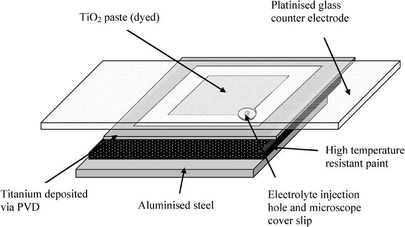
Schematic illustration of geometry of DSC on organically coated steel substrate
Current voltage I–V measurements
The current voltage characteristics of the cell were measured using an Oriel Sol3A (94023A) utilising a Xenon arc lamp (150 W), an AM1·5 filter and a Keithley 2400 source meter. A certified (Oriel 91150V) monocrystalline silicon reference cell traceable to the US Department of Energy National Renewable Energy Laboratory was used to adjust the solar simulator to the standard light intensity of one sun, i.e. 1000 W m−2.
Results and discussion
The physical vapour deposition (PVD) deposited 1·2 μm Ti layer showed generally excellent adhesion to the organically coated steel substrate and could not be removed using industry standard tape pull off tests. The layer itself was continuously displaying a sheet resistance of 6·7 Ω/sq as tested using a four‐point probe method. This compared favourably to glass mounted 1·2 μm Ti layers (5·9 Ω/sq) prepared under identical deposition conditions and is of a higher resistance than that displayed for 1 mm thick Ti coupons (as shown in Table 1) due to the relatively high resistance of the thin deposited film. In this respect, the deposited layer seemed to be performing as would be expected for a microfoil electrode. Heating of the system at 450°C for 30 min did, however, degrade the conductivity of the Ti layer applied to the prepainted aluminised steel surface as shown in Table 1. This was not the case for either the Ti coupon or glass mounted PVD layer where there was a slight improvement in conductivity following heating. The fall off in Ti layer conductivity in the prepainted steel samples can be explained by considering the nature of the Ti layer post sinter. Figure 2 illustrates an optical micrograph of the sample post‐sintering (without a titania layer). It can be seen that there is considerable surface microcracking in the material, and this reflects a serious mismatch in thermal expansion properties between the trial high temperature epoxy organic binder and the PVD Ti layer. No cracking was observed on glass mounted Ti layers of the same thickness (which is consistent with the improved conductivity in these systems shown in Table 1). This cracking leads to a large potential variability in post‐sinter sheet resistance (as shown by the standard deviation in measurements for separate samples in Table 1).
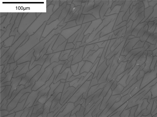
Optical micrograph showing microcracking of 1·2 μm PVD titanium layer on prepainted aluminised steel following heat treatment at 450°C for 30 min
Four‐point probe determined sheet resistance values for Ti coupons (1 mm) and PVD layers of Ti (1·2 μm) deposited on glass and prepainted steel substrates before sintering step and after application of heating step at 450°C for 30 min without prior titania deposition
Figure 3 shows the I–V curves produced from a DSC on Ti sputtered organically coated steel compared to DSCs produced under identical conditions on 1 mm thick Ti. It can be seen from Fig. 3 and the average cell performance data in Table 2 that the 1 mm Ti sheet and 1·2 μm PVD Ti prepainted aluminised steel mounted DSC performance is reasonably comparable. In both cases, the efficiency is lower than that obtained on glass since the cell is essentially in a reverse set‐up with light travelling through the iodide/tri‐iodide electrolyte.
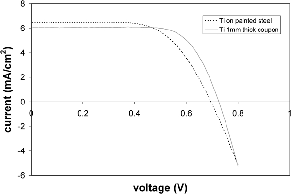
Typical current voltage curves at one sun for DSCs prepared on 1 mm thick Ti coupons (solid line) and Ti vapour deposited (1·2 μm) on prepainted aluminised steel substrates
Efficiency data for 1 cm2 DSCs mounted on 1 mm Ti coupons and on 1·2 μm thick PVD Ti mounted on prepainted steel substrates at one sun illumination
The 1 mm Ti coupon data presented shows that the organically coated steel cell still has some way to go to match a solid substrate. The lower fill factor indicates that the increased sheet resistance caused by Ti layer microcracking (illustrated in Fig. 2) is the primary reason for the lowering in cell efficiency. There is clearly a coefficient of thermal expansion (CTE) mismatch between the polymer and the Ti microlayer, and the current work is aimed at matching the performance of the layers in heating steps and to further understand what role oxidation plays in changing the sheet resistance of microlayers of Ti on organic binders. Oxidation is evident through the creation of multicoloured surface effects on the titanium surfaces on heating. Further efficiency gains could also be possible by secondary treatments, such as TiCl4, or through the inclusion of scattering particles in the titania paste material. In addition, the electrolyte used here has not been optimised for reverse cell set‐up (i.e. the high tri‐iodide concentration reduces the photons reaching the sensitising layer, whereas in the forward set‐up, the first layer that the photons hit is the sensitising layer on glass). Nevertheless, the 1·2 μm PVD titanium layer on prepainted aluminised steel has been shown to be capable of providing sufficient electron transport to sustain a DSC at an efficiency of ∼3%. This provides an intriguing method for creating a steel based DSC in one embodiment, by roll to roll processing. In other words, following paint curing, a metallisation unit could be incorporated to apply a Ti (or another metal layer), which would then form the basis of subsequent printed and roller coated dye cell components. Furthermore, given that deposition of TiO2 via magnetron sputtering has already been demonstrated elsewhere,8 – 13 there is an opportunity to use this method to not only isolate and metallise the underlying substrate but also deposit the nanoporous TiO2, entirely within one PVD operation. This proposal is however not without its challenges. First, the deposition rates via the authors’ laboratory unit are very slow. Commercial industrial coating lines would need to operate at speeds of 20–120 m min−1. With a coating time of 2 h, this is clearly a limiting factor. Physical vapour deposition is, however, a technology that is being explored for industrial application of micrometre scale metallic coatings. The major challenges are creating a roll to roll vacuum lock and ensuring consistent and fast deposition. The development of electron beam evaporation should assist with the latter, and the former is already being addressed in work aimed at functionalising thin polymer films and in the development of galvanised products with a micrometre additional layer of elements such as magnesium. The second challenge is to address thermal mismatch. First, what can be altered is the nature of the organic layer. The epoxy coating used in this work was chosen, as it had known heat resisting properties and good adhesion to the aluminised substrate and so could be used to show potential in this early demonstration. The choice of a different polymer with a CTE closer to Ti would help reduce cracking. It is also the case that multitarget PVD offers the opportunity of laying down several metal layers consecutively or creating an alloy material with a closer match to the CTE of the polymer. The third challenge links to the first two and that is to reduce the cracking and maintain both the corrosion barrier properties of the Ti layer and create good conductivity. Alongside these production challenges for the substrate are further exciting possibilities. A parallel work is underway to lower the sintering temperature for the TiO2 thereby allowing for the use of a galvanised substrate coated with a polyurethane or similar architectural coating, which will support external weathering capabilities. Despite these challenges, the attraction of the DSC is that it lends itself well to roll to roll processing and is a technology that is far more developed than organic photovoltaics, which will be an important next generation of coating for such products.
Conclusions
This work has shown that a DSC can be manufactured directly onto prepainted aluminised steel in one embodiment using magnetron sputtered titanium. This DSC is capable of achieving 2·9% photovoltaic conversion efficiency compared to a solid Ti electrode produced under identical conditions of 3·2%. The principal reason for the lowering of efficiency of the thin PVD layer on prepainted aluminised steel is a lower fill factor, which is directly related to the microcracking introduced by differential CTEs, which increases sheet resistance. Current work is underway to investigate variations to the polymer type and coating pigmentation to obtain a closer match in thermal characteristics and to explore multilayer magnetron sputtered metals. Developments in low temperature sintering also offer the potential to expand the substrate choice to include galvanised zinc–aluminium alloy coated steels, which are more typical of those used for high durability construction products.
Footnotes
Acknowledgements
The authors would like to acknowledge financial support from the Engineering Physical Science Research Council (EPSRC EP/E035205) and Corus Colors, PV Accelerator, Shotton Works, Deeside. Discussions with Dr Brian O’Regan at Imperial College London on cell building methodologies and with Dr Zak Barrett on the operation and use of the Kurt J. Lesker PVD 75 were invaluable.