
Abstract
In a number of thin slab caster/hot strip mills, a serious vibration phenomenon can occur in F2–F4 stands during rolling thin gauge or high strength strip. In particular, the vibration of compact strip production (continuous) hot rolling mills is a more serious and difficult technical problem to resolve. When vibration occurs, chatter marks occur on the mill rolls and strip surface together with excessive noise. The problem not only reduces the life of the rolls but also poses a threat to the safety of the production equipment, having triggered a number of major accidents in the past. Following vibration theory study, computer simulation and field tests, measures were implemented to control the vibration, which achieved significant results and economic benefits.
Introduction
The first compact strip production (CSP) hot rolling mills from SMS Company went into operation in the USA in 1989. Since 1998, 13 thin slab continuous hot rolling mill production lines have been installed in China. There are three types of hot rolling mills: the CSP hot rolling mills from SMS Company (Germany), the flexible thin slab hot rolling mills from Mitsubishi (Japan) and the Angang strip production hot rolling mills from AnSteel (China). These mills all produce abnormal vibration. Chatter marks occur on the rolls and strip surface together with excessive noise.1,2 In particular, the vibrations of F2–F4 stands are more apparent. When vibration occurs, not only does this seriously affect the quality of the strip surface and the development of new products, but it is also a threat to the safety of production equipment. Furthermore, roll changes or process specification changes were more frequent.3 – 5
Integrated field test and single analysis
Field testing was carried out on the F3 stand of a specific company, including 55 testing parameters, such as the mechanical, electrical, rolling process and vibration parameters. The testing system is comprised of four parts, including the mill online monitoring system, bending and torsional vibration remote testing, process data testing and vibration signal testing.
As depicted in Fig. 1, the torque and bending moment for the F3 stand are shown as strip bites. The torsional vibration parameters of the two spindles simultaneously reached a maximum and then attenuated and reached a relatively stable oscillation state. The torsional vibration frequency is ∼19·8 Hz, which is the first order natural frequency of the kinematic chain. At the same time, the bending vibration parameters also produced the phenomenon of free vibration attenuation and frequency at ∼35 Hz.
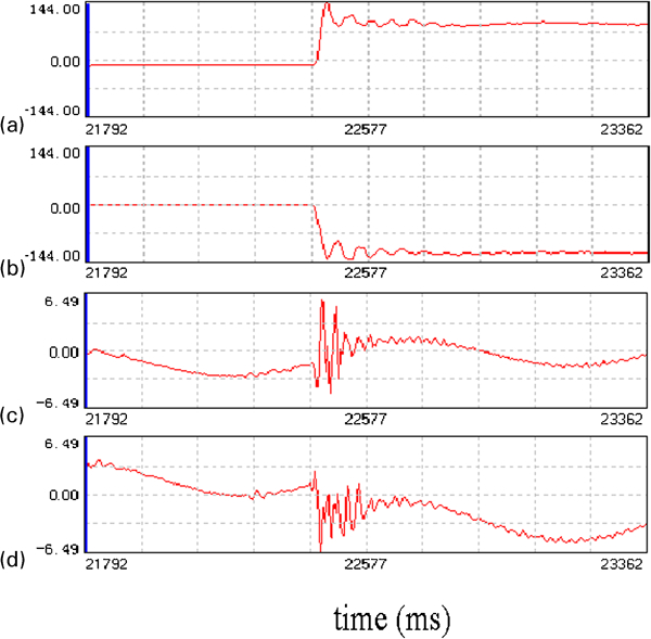
Waveform diagram for bending and torsional vibration parameters of top and bottom universal joint spindles in normal working condition
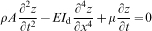
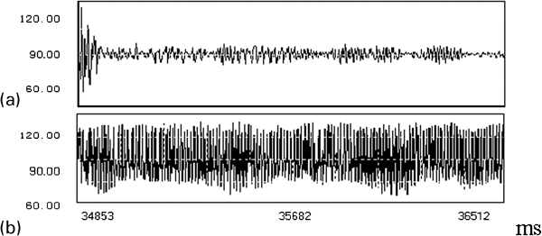
As depicted in Fig. 2, when noticeable vibration happens, the torsional vibration parameters of the top and bottom universal joint spindles have a clear coupling vibration phenomenon. Through spectral analysis, the dominant frequency of vibration is 42·75 Hz.
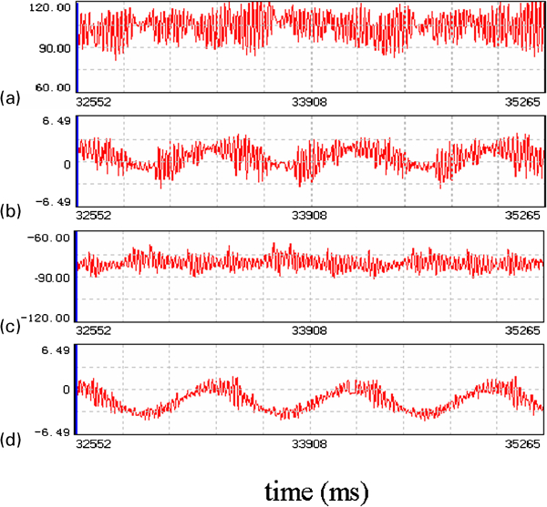
Waveform diagram for torsional and bending vibrations of top and bottom universal joint spindles when noticeable vibration is occurring
The testing results showed that the F3 vibration has a strong coupling vibration phenomenon, which required a more in-depth theoretical vibration study. The following three aspects were simulated to provide a theoretical basis to ascertain the origin of the vibration: coupling of torsional and vertical vibration, coupling of bending and torsional vibration and electromechanical coupling vibration.
Vertical torsional coupling vibration
In the past, research into rolling mill vibration concluded that torsional vibration in the mill drive system could not transmit to the vertical system.6 – 8 However, in the mill vibration test, it was found that the frequency of torsional vibration was contained in the vertical vibration signal. This phenomenon was explained by theoretical research as follows.
First, the ANSYS software was used to build a finite element model of the vertical system in accordance with the actual mill size (Fig. 3).
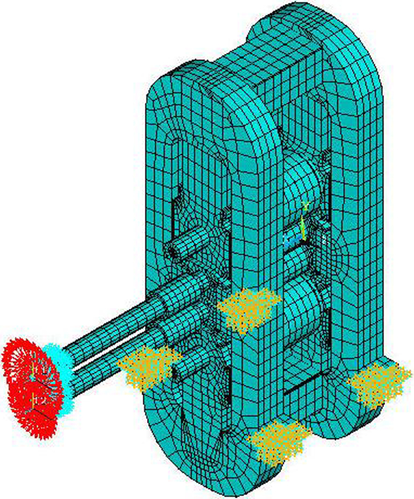
Finite element model of CSP mill
In order to study the influence of torsional vibration on the vertical vibration of the system, the driving torque M, which is the same as the field test numerical value, was imposed to the universal joint spindle, as expressed approximately by the following equation9


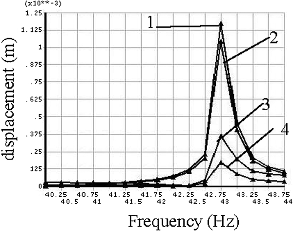
Then, the response of the vertical system under the effect of the driving torque was studied using the harmonic response analysis module in ANSYS to obtain the frequency–displacement curve of the rolls. Figures 4 and 5 display the frequency–displacement curves of the roll system in the X and Y directions respectively at intervals of 0·25 Hz for a total of 16 frequencies from 40·25 to 44 Hz.

Frequency–displacement curves of roll system in X direction
Frequency–displacement curves of roll system in Y direction
According to the figures, the roll system produces a different response amplitude under the different frequency driving torques, with the response of the horizontal direction being larger than that of the vertical direction, but both with a peak amplitude of 43 Hz. Therefore, the horizontal and vertical vibrations of the mill roll system are enhanced if the frequency of the driving torque approaches this value. Thus, torsional vibration can lead to vertical vibration.
Contrasting the displacement values in the X and Y directions, it can be seen that the top mill roll system displacement (vibration) is larger than that of the bottom mill roll system.
Bending torsional coupling vibration
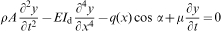
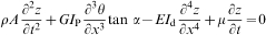
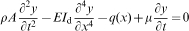
First, microelement axis segments of the universal joint spindle were intercepted. These take into account the influence of mass unbalance, deadweight, spindle angle and damping. Then, the torsional and bending vibration differential equation of the universal joint spindle was built through force and moment balance relations of the microelement axis segment.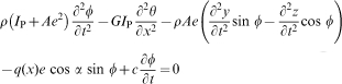
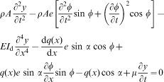
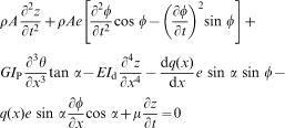
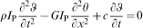
From the differential equations, there is a clear coupling relationship between the bending and torsional vibrations.
When mass unbalance does not exist (e = 0), differential equations (1)–(3) become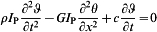
Electromechanical coupling vibration
It is found that the main form of rolling mill vibration is torsional vibration, the frequency of which is ∼42·75 Hz through comprehensive tests (Fig. 6).
Waveform diagram and torque spectra of mill spindles during vibration
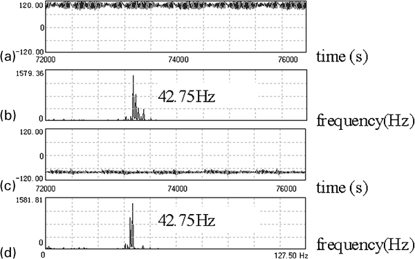
When state observer (Fig. 7) is added into the simulation model of the main driving control system, torsional vibration of the spindle (42·75 Hz) is observed. A simulation model of the electromechanical coupling in Matlab/Simulink is shown in Fig. 7.
Simulation model of control system with dimension state observer included (Kp: ratio of speed regulator magnification factor; Tn: speed regulator integral time constant; K: current regulator proportional amplification factor; Ts: current regulator integral time constant; 2·5: motor speed/rev min−1; Me: load torque; Kn: speed difference gain coefficient)
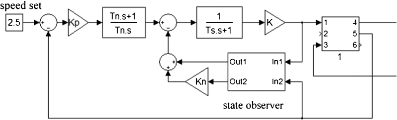
When the main driving control system has a second order torsional vibration, the observer will use the oscillation caused by disturbance the same as that of the second order vibration frequency on the driving control system to compensate the oscillation in order to achieve stable operation. Using this method of compensation, the rapid nature of its role is mainly because the compensation loop can generate oscillation the same as the actual driving control phase synchronous oscillation signal as the feed forward control directly involved in regulating the effect of its control, as shown in Fig. 8.
Signal of spindle torque before and after dimension state observer included
As can be seen from the figures, after the state observer is included, the second order torsional vibration amplitude is significantly reduced; that is, the second order torsional vibration suppression of the rolling mill main driving control system has been largely eliminated. The first order natural frequency of the driving control system torque signal still exists at the bite; then, it rapidly disappears.
Simulation results indicate that the purpose of the second order torsional vibration suppression of the rolling mill main driving control system has been achieved with the use of the state observer.
After field testing and simulation analysis, it was found that the second order torsional vibration of the rolling mill main driving control system has also become the main form of vibration, and the existing motor control system cannot inhibit it. Therefore, a state observer as described in this paper, which can suppress the second order torsional vibration and provide simulation, was used to analyse the effect that the motor control system suppresses the second order torsional vibration of the rolling mill main driving control system. Simulation analysis showed that using the state observer can achieve the purpose of the second order torsional vibration suppression of the rolling mill main driving control system.
When a state observer is used in the rolling mill main driving control system, second order torsional vibration (42·75 Hz) is restrained (Fig. 9), and remarkable success is gained.
Actual torque signal of spindle torque with dimension state observer included
Conclusions
The theoretical studies and test results show the following:
A strong coupling vibration occurred in the main drive system of the rolling mill.
In order to suppress second order torsional vibration, a feedback loop called state observer was designed and used in the rolling mill main drive system. The results showed that using the state observer can suppress the second order torsional vibration of the main drive system of the rolling mill.
The practical application of the state observer in the F3 stand mill with the optimised parameters effectively suppressed the second order torsional vibration.