
Abstract
Based on the laser triangulation and machine vision technology, a three-dimensional quantitative inspection method for continuous cast slab surface defects was established, which adopted one laser and two array charge coupled device cameras and an optimal laser stripe imaging algorithm. In addition, the laser scanning system establishing method is described in detail in this paper. A laser stripe edge shape extraction method on the slab surface is proposed that utilises an improved edge scanning extraction model in accordance with the charge coupled device camera frame frequency. The detection accuracy control algorithm is presented and finally the three-dimensional image reconstruction method for slab surface defect shape was also studied. Based on the research work, the possibility of the presented laser scanning system was verified through industrial application experiments in a steel plant.
Introduction
Early surface defect inspection in hot steel products is a difficult task, but successful inspection can help significantly reduce production costs and increase productivity. Such is the complexity of the steelmaking and continuous casting process: surface and inner cracks or other types of defects may occur. With reference to surface defects, it is their depth that can lead to serious problems in the subsequent manufacturing stages.1,2 In continuous casting, three occasional surface defects on slabs and an example of some are shown in Fig. 1.
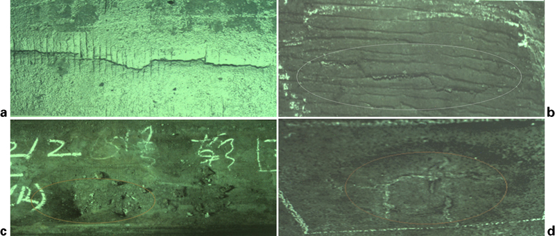
Common defects in continuously cast slab
Owing to the specialty of the continuous casting process, particularly hot charge rolling and continuous casting–direct rolling technology, which requires continuous operations for the entire procedures, a necessity is an online, non-contact and high precision inspection technology for surface defects. Obviously, the successful application of this technology also plays a supporting role for the production integration in iron and steel enterprises.
Different types of cracks in the slab surface are the main defects that directly affect the yield and quality off the caster. For example, if longitudinal depth exceeds a given degree, holes and/or through thickness cracks may result in final rolled and finished products. With respect to the aspects of surface defect detection technology on hot continuously cast slab, a lot of research work has been done by researchers from different countries to overcome the challenges. For example, Mei et al. 3 employed infrared non-destructive testing (NDT) technology with the data interpretation based on a generic algorithm. Rinn2 from Parsytec Inc. in Chicago, using multiple area array charge coupled device (CCD) field image overlapping method, expanded the testing scope in the width of steel plate and this detection system has been developed and applied to the industrial field. In addition, Rafajlowicz et al.4 adopted a different timing of radiation image data fusion technology to inspect surface defects on continuously cast slab. Fabijanska and Sankowski,5 according to the information fusion technology, developed an inspection method related to surface and subsurface defects in continuously cast slab. Álvarez et al.6 at Ovid University in Spain studied a three-dimensional (3D) quantitative detection method through laser interference holography and image processing technology, which realised in an industrial application on hot slab, more than 900 surface defects online. Favro et al. 7 at Wayne State University in the United States, based on the thermal wave inverse scattering theory and the Green’s function method, established a specific relationship (without considering the thickness of the object) between the corresponding surface temperature in the defect centre and the depth of defect, the radius and the pulse heating time. This inspection technology requires the object to have imposed a high excitation energy pulse and simultaneously collect specimens of image sequence for analysing the existing subsurface defects. Obviously, on account of the considerable thermal diffusivity of steel, there will be a short time when the achieved image has the maximum contrast value, which will result in lower detection sensitivity for the dynamic hot slab defect detection. This method has many disadvantages and furthermore, owing to the information interference on hot slab surface, such as the water film or oxide scale, it is difficult for the traditional optical imaging method to select an appropriate threshold segmentation algorithm for the CCD greyscale image and precisely extract the regions of interest on the slab surface. Therefore, this means a high probability of misrecognition of the defect.
In this paper, based on the previous researches mentioned in Ref. 1, a laser scanning inspection system was developed using dual area array CCD camera image data fusion technology, which was developed for 3D quantitative detection for slab surface defects in the continuous casting process. In addition, the detection accuracy of defects in 3D shape with minimum occlusion problem was improved through the symmetric CCD cameras and image data fusion technology and the optimal imaging method of the laser stripe projected on hot slab surface studied. The feasibility of this laser scanning system (LSS) was tested on the steel plant during industrial experiments.
Establishing method of proposed system
The LSS included a linear He–Na laser emitter (line width of 1 mm) that projects vertically over the slab surface and two area array CCD cameras that are symmetric with the laser optical irradiation routing; the installation architecture is shown in Fig. 2. The system was designed by the following rules, where: θ = θ′ and CCD-1 and CCD-2 simultaneously capture the thin laser line when the LSS is running. Based on the principle of laser triangulation, the given angle between the laser line and the CCD camera central optical axis can translate distance changes of the slab surface into lateral displacement δ of the light spot on the CCD focus plane or in a recorded image. The conversion formula can be expressed as below,8 taking CCD-1 as an example (in Fig. 2.); similarly, CCD-2 follows the same rules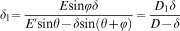

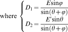
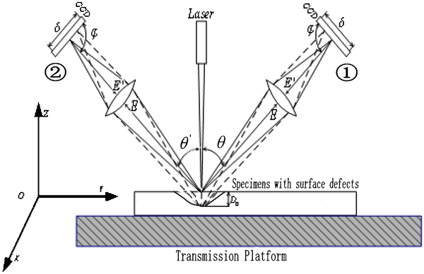
Schematic diagram of dual CCD sensor system for slab surface defects inspection
where θ is the angle between laser line and CCD lens axis related to the slab surface’s normal, φ is the angle between lens axis and CCD focus plane, δ l isx the lateral displacement corresponding to the depth changes in inspected object surface and E and E′ represent the object distance and image distance in the baseline distance respectively.
Data processing for CCD-2 is treated in the same way as for CCD-1. Since the laser stripe has a certain width of 1 mm, in order to ensure the real time speed of the CCD image scanning and processing, the cameras scan the right and left edges of the laser stripe respectively and in accordance with the slab casting speed, the CCD scanning lattice images are fused into one image. This approach to data processing can guarantee the shape integrity of slab surface defects and thus the defects can be captured by the LSS with minimum occlusion.
Charge coupled device optimal imaging method for laser stripe
To precisely extract the morphological features of the laser stripe edge features by the CCD sensors is an all important precondition, which will determine the system detection accuracy. The acquisition method of laser stripe double edges proposed in this paper provides a technical solution for fast laser scanning in this field of research and meanwhile it can considerably reduce the measurement error that is commonly caused by artificial CCD definition adjustment with regard to the optimal imaging method of laser stripe shape on slab surfaces. There are differences in photosensitivity for different types of CCD image sensors, and for high brightness light source, such as linear He–Na laser emitter, the CCD imaging features of laser stripe are manifest as three different contour features under different apertures and optical integration times (OPT). These are described as follows:
partial fracture of the laser stripe edges (CCD OPT is too short)
optimal connectivity state (optimal OPT)
laser stripes light intensity scattering (OPT is too long).
Therefore, the OPT of CCD focus plane photosensitive element must be adjusted automatically before scanning by the software using a definition controlling algorithm to find the optimal connectivity state of laser stripe. The image features under different aperture settings and OPTs are shown in Figs. 3 and 4.
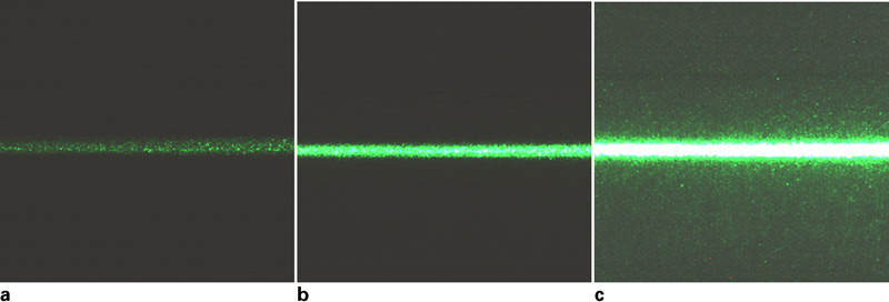
Laser stripe imaging features at F8 aperture setting under different OPTs
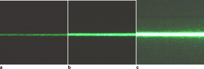
Laser stripe imaging features at F4 aperture setting under different OPTs
Through the analysis above, the conclusion may be drawn that under a specified aperture setting, the laser stripe imaging features are related to the magnitude of the CCD OPT. The optimal imaging method of the laser stripe that is presented in this paper is thus. The average gradient t(AG) of a series of CCD original images was calculated under fixed aperture settings and different OPTs. The OPT corresponding to the second curve minimum point in the y coordinate is the desired OPT for CCD laser stripe imaging. Accordingly, the best imaging features of the laser stripe can be determined using this controlling algorithm, as shown in Fig. 5.
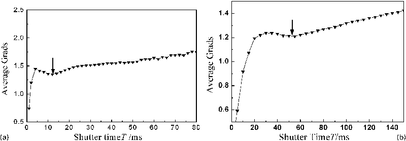
Average image gradient changes under different aperture settings and integral times
The laser stripe definition controlling algorithm that is adopted in the LSS is explained as follows. The three representative laser stripe imaging shapes, depending on a given OPT (in Fig. 5: F4-F8), including laser stripe edges partial fracture, optimal connectivity state and light intensity scattering correspond to the first maximum point of the AG curve (at shutter times of 4 and 33 ms), the second AG curve minimum point (at shutter times of 12 and 55 ms) and the rapidly increasing point on the AG curve (at shutter times of 20 and 70 ms) respectively. The reasons for the use of the average gradient of the laser image are:
the laser stripe itself had a small gradient value (smoothly connected)
the laser line had the largest edge gradient value only with the image background
there was one gradient value that existed between the light scattering spot of laser stripe and image background.
Consequently, the image average gradient reflects the small details of the image contrast and the variation characteristics of image texture. To take the image resolution by n×m for example, the average gradient can be defined as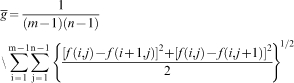
In summary, the optimal image acquisition method of laser stripe can be obtained by CCD cameras through finding the second state of local minimum point on average gradient curve using automatic controlling algorithm designed by software.
Charge coupled device signal processing method and examples
In order to guarantee a given accuracy for the two-dimensional (2D) areas that are determined by the CCD vertical height and the number of CCD pixels, the system real time inspection data and displacement encoder signals must be sent into an interprocess communication processing module simultaneously, which requires that the CCD cameras scanning image must be processed in the same sequence. The CCD frame scanning frequency was set by a specific algorithm based on the real time casting speed signal. In addition, by adjusting the angle between the CCD focus plane and the normal to the slab surface, the maximum inspected depth for surface defects can be accurately calibrated, which can competently meet the requirements of slab quality assessment. In the laser scanning process, the 2D scanning mosaics grey image of laser stripe were mapped separately to corresponding processing modules (three designated buffers):
3D defects morphology reconstruction
2D surface area calculation
the maximum depth measurement.
The methods of CCD signal acquisition, data fusion process and data flow are shown in Fig. 6.
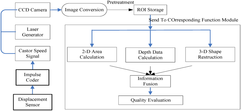
Processing procedure of entire detection system
Software and specimen detection examples
In order to guarantee the surface quality of continuously cast slab, the surface must be observed in real time. The designed scanning software has four display windows in the main interface that have four functions as illustrated in Fig. 7. Window 1 on the top left corner displays the original laser image and the adjusted shape, which is regulated by the optimal laser stripe acquisition algorithm mentioned in the section on ‘Charge coupled device optimal imaging method for laser stripe’. Window 2 at the top left is the laser scanning greyscale mosaic image. Windows 3 and 4, at the bottom left and bottom right respectively, show the 2D shape and the 3D reconstructed images. The slab surface morphology can be observed through different windows while the system is running. Meanwhile, the operating parameters for continuous casting can be regulated online, based on the observation and inspection results.
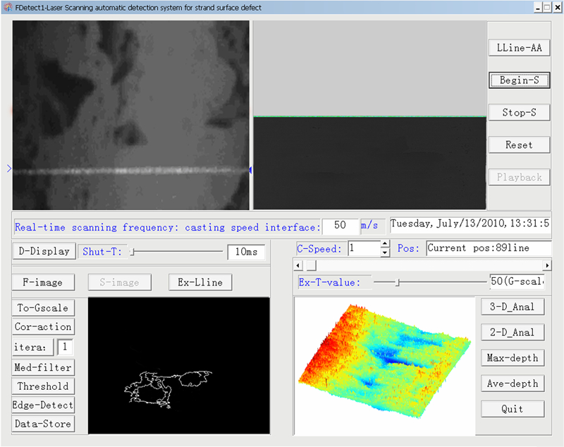
Software main interface
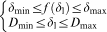
The texture image features on the slab surface are generally manifest by their irregular shape, that is, it is difficult to accurately extract the regions of interest from the original image, even with high resolution image sensors. Therefore, the data processing quantity is considerably increased and the design of the recognition algorithm is more difficult. In the next step, the recognition algorithm will be simplified to avoid causing a higher false recognition rate for defect inspection. In addition, removing the pseudo defect information (oxide scales and/or water film) by conventional optical NDT methods is also a thorny problem. The defect inspection methods designed in this paper, based on the distance information from the slab surface and dual CCD image data fusion technology can effectively eliminate the interference of image colour features and it is beneficial to the integrity of 3D defect morphology, especially for small defects such as the slab surface blowholes and transverse cracks. As shown in Figs. 8 and 9, the scanning images of manmade specimens include three common types of slab surface defects, which were captured by the CCD-1. The 3D reconstructed images made through the data fusion of CCD-1 and CCD-2 images are shown in Fig. 10. According to equation (2), the CCD sensor image data fusion method can be expressed as follows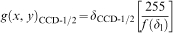
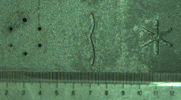
Simulated defects in continuous casting slab surface
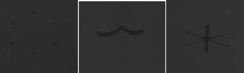
Laser scanning images
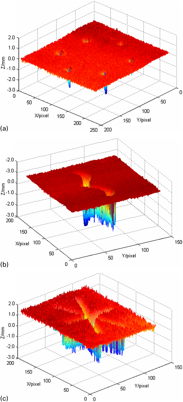
Quantitative 3D reconstructed images
where D min and D max represent the minimum and maximum inspection depths respectively.
The ultimate image grey value after camera image data fusion can be expressed by
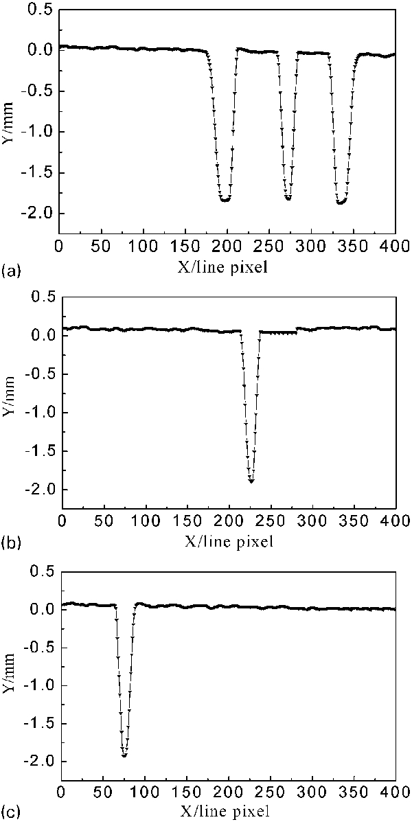
Searching results of maximal depth of defects in laser scanning image
Industrial application experiment
The onsite LSS consisted of three indispensable parts and the installation method included the following procedures:
the high precision linear laser device was installed in the horizontal direction and projected vertically on the slab surface. The laser emitters were installed behind a high temperature shielded cover that was made of a double magnesium alloy, which adopted clean nitrogen cooling. The laser was installed in accordance with a given angle with the CCD focus target and slab surface datum plane
CCD-1 and CCD-2 image sensors were installed symmetrically at both sides of the laser that was used to extract the laser line shape on slab surface. The CCD cameras were fixed in high temperature protection hoods that had installed a narrow band optical band pass filter in front of the camera lens, which can prevent the red light radiation interference of hot slab
to ensure detection precision for 2D and 3D defects, in the junction of the CCD cameras and the laser, an angle adjusting device was installed, which was applied to calibrate the relationship between laser scanning distance lattice and the converted image grey value
the pulse generator installed in the continuous casting roller sent a precise displacement signal of cast slab into the interprocess communication in real time, which was used to control the CCD sensor frame scanning frequency.
The specific installation architecture mentioned above is shown in Fig. 12.
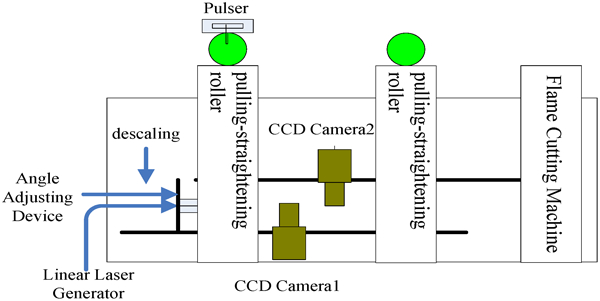
Schematic diagram of system installation architecture
Online NDT technologies for the detection of surface defects on hot continuously cast strands in both the domestic and international iron and steel companies are a research focus and the technology described in this paper can play a key role in promoting the hot charging or direct rolling rate route in continuous casting. However, the technology may also be applied to other material production fields and may also play a supporting role in the development of industrial automation. By industrial application experiments, the feasibility of this new system was verified on a continuous casting production line. The original image (without descaling) of the laser line captured by a general camera on the continuously cast hot slab is shown in Fig. 13a ; the morphology of laser stripe on the hot slab surface can be clearly seen. The 3D reconstructed image of the slab surface pit defect onsite is shown in Fig. 13b and c . Figure 13d shows the displayed 2D edge detection region of the defect.
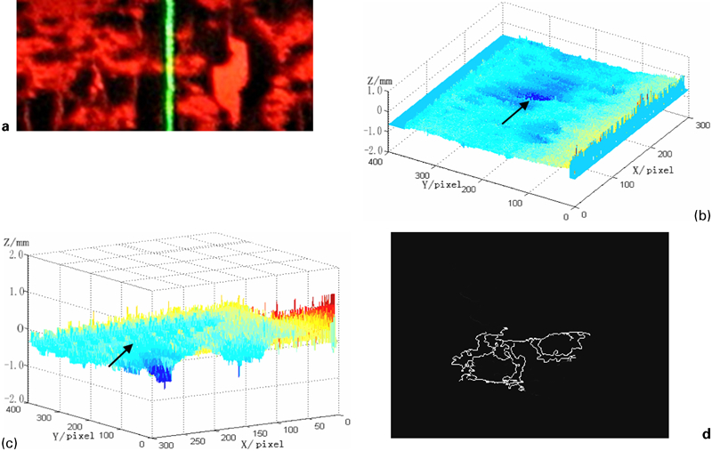
Results from field experiment
Conclusions
The laser scanning method system designed for hot strand surface defect inspection in this paper is applicable to 2D and 3D defect morphology detection, which has a wide inspection range. In addition, it can offer the assessment for surface quality of the strand online and is reflected especially in the following points:
Based on the machine vision technology and the laser triangulation distance measurement, a 3D quantitative laser scanning defect inspection method was established using dual CCD image sensor data fusion technology. Moreover, a detailed description of the hardware and software system design methods has been given.
The traditional method of image acquisition has been improved in respect of the grey image that is converted from the laser scanning distance dot matrix scanned by the CCD cameras to 3D surface topography information of the inspected object.
The optimal extraction algorithm for the laser stripe image was established based on the integration time control principal of the CCD photosensitive element and through the real time scan detection for the specimen.
The feasibility of this system had been verified in plant.
Footnotes
Acknowledgements
The authors wish to express their appreciation to the National Natural Science Foundation and Shanghai Baosteel joint project support (grant no. 50974151). The authors also thank Chongqing University for their assistance in taking some of the experiments.