
Abstract
A software to simulate the solidification, heat transfer and water flowrate distribution in slab continuous casting was developed by establishing a mathematical model for the heat transfer and solidification in medium thickness slab casting. This model was validated by pin shooting and surface temperature measurement experiments. A reasonable target surface control temperature was found by testing the high temperature mechanical properties of Nb bearing ship plate steel, and then the water flowrate of each loop of the secondary cooling zone was determined by the software. The influence of uneven secondary cooling in the slab width direction on the quality of the slab was also investigated, which provided data for the optimisation of the secondary cooling of the slab caster. On the basis of the above research, an optimisation scheme for a secondary cooling system was proposed. Experimental results showed that the quality of the slab was significantly improved after optimisation. The centreline macrosegregation was reduced, and the ratio of equiaxed grains was increased by 3·18%. In addition, the transverse cracking of the slab was almost eliminated.
List of symbols
constant (a is 15·8847, and b is 0·011495)
specific heat capacity of steel, J kg−1 °C−1
specific heats of solid steel, liquid steel and steel in the mushy zone, J kg−1 °C−1
specific heat capacity of water, J kg−1 °C−1
elastic modulus, GPa
solid phase fraction
gravity constant (9·8 N kg−1)
heat transfer coefficient, W m−2 °C−1
complex heat transfer coefficients on the broad and narrow surfaces of slab, W m−2 °C−1
the distance between meniscus and force bearing point, m
latent heat, J kg−1
effective length of mould, m
the distance between meniscus and microunit, m
heat flux, W m−2

average surface heat flux, W m−2
water flowrate of mould, kg s−1
effective cooling region of mould, m2
temperature, °C
temperatures of strand surface, cooling water and environment, °C
liquidus and solidus of steel, °C
casting speed, m min−1
the flux of cooling water, L m−2 s−1
ferrostatic pressure, N m−2
temperature difference between inlet and outlet water of mould, °C
mesh size of slab in its width and length directions (8 and 4 mm in this paper)
radiation coefficient (0·8 in this paper)
thermal conductivity coefficient, W m−1 °C−1
thermal conductivity coefficients of solid steel, liquid steel and steel in the mushy zone, W m−1 °C−1
Poisson's ratio
density of steel, kg m−3
Stefan–Boltzmann constant (5·67×10−8W m−2 K−4)
time, s
Introduction
The as cast quality of continuously cast slab depends on the design and levels of maintenance of the casting machine, the casting process operation and the steel’s chemistry. The cast slab passes through three cooling regions: the mould cooling zone, the secondary cooling zone and air cooling zone. The cooling conditions at the mould and air cooling zones are relatively stable for a given caster when specific equipment is used, with only the secondary cooling zone capable of being adjusted within a larger range. Moreover, the secondary cooling is an important factor affecting the quality of the slab, and this has been investigated by numerous researchers worldwide over a long period.1 – 7
A mathematical model of the heat transfer for slab casting was established on the basis of the research on the heat transfer process, and the corresponding numerical simulation and control software were then developed. Satisfactory results were achieved using optimisation technology8 – 10 for the secondary cooling system on CCM2 at the no. 3 steelmaking plant of Hansteel. The model can be used to optimise the secondary cooling control and predict the final solidification position of the slab, which provides an important guide for continuous casting production.
Mathematical model of slab solidification
Heat transfer differential equation during solidification process
The molten steel is moved constantly down from the mould meniscus with the heat transfer, and the amount of heat transfer depends on the thermophysical properties of the steel and the cooling conditions during the casting process. To simulate the temperature distribution in the slab, a mathematical model of the heat transfer needs to be established. Moreover, a microunit is considered to move down from the meniscus with the casting speed, where the length, width and height of this microunit are dx, dy and dz respectively, as shown in Fig. 1.
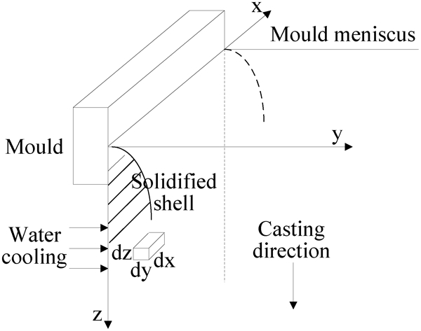
Scheme of microunit of slab during casting
The assumptions proposed in the authors’ previous research10 are adopted in the present paper to simplify the model. On the basis of the heat balance of the slice, the unsteady heat conduction equation for the slab can be expressed as follows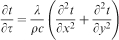
Boundary conditions of heat transfer differential equation
The solidification of molten steel is a process of heat release and transfer. To solve equation (1), the boundary conditions need to be determined for the mould, water spray cooling zone and air cooling regions.
Heat transfer in mould
From the cooling water flowrate temperature difference between the inlet and outlet of the mould, the average heat flux in the mould can be described by equation (2)11

Heat transfer in secondary cooling zone
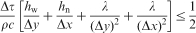
Two types of nozzles were chosen for the secondary cooling zone of CCM2: water only nozzles and air mist nozzles. Usually, water only nozzles are arranged within the foot roller segment, and air mist nozzles are distributed throughout the remaining secondary cooling segments. The boundary conditions in the secondary cooling zone can be expressed by equation (5)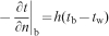

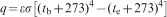
Heat transfer in radiation or air cooling zone

Physical parameters of steel
Liquidus and solidus temperature of steel
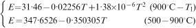
The liquidus and solidus temperatures of steel are related to its chemical composition. In this paper, the relevant discrete data are obtained from the latest Fe-i binary phase diagram and fitted by the least square method to find a new formula for the calculation of the liquidus temperature of steel. The model was verified by data from the literature, and the results show that the liquidus temperature deviation between the measured and predicted values using the present model is between −3 and +4°C,13 i.e.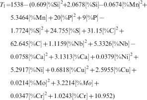
Density of steel
The density of steel is assumed to be constant because it is relatively stable in each state during the casting process. The density of solid steel is considered to be 7400 kg m−3, while a value of 7000 kg m−3 is used for liquid steel and 7200 kg m−3 for steel in the mushy region.
Thermal conductivity coefficients
Generally, the thermal conductivity of steel is related to its temperature. In the present model, it is assumed that the thermal conductivity of solid steel has a linear relationship with temperature,14 i.e.

Specific heat capacity and latent heat of solidification
In general, the specific heat capacity increases with temperature, whereas it changes very little at high temperature. Therefore, the specific heat capacity can be treated as a constant in solid steel and liquid steel. In the model, the sensible heat method, that is to say, the latent heat of solidification, which is taken into account as the specific heat capacity of the steel, is chosen to deal with the latent heat of solidification. Thus, the specific heat capacity of the steel in the mushy zone can be expressed by equation (15)17
Development of calculation software
The simulation and control software for the solidification and heat transfer of a slab was developed using the software Borland Delphi 7·0. The main functions of the model are as follows:
the collection of process parameters, including steel grades, operational conditions, machine characteristics and environmental conditions
offline calculation of the temperature profile, liquid pool length, solidification shell thickness, etc.
calculation of the water flowrate distribution in the secondary cooling zones, which should conform to the demands of the metallurgical optimisation criteria.
The chemical composition of the steel grade Q420B is 0·165C–0·421Si–1·477Mn–0·018P–0·004S–0·029Nb–0·008Ni–0·01Cu–0·003Mo–0·019Cr. The temperature field of a slab is calculated under the given casting conditions, and an example of the interface of the temperature field of the foot roller outlet is shown in Fig. 2. The locations of the points and their corresponding temperatures can be obtained by moving the cursor in the temperature field.
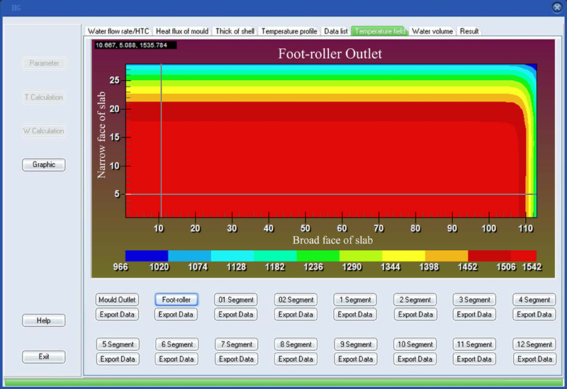
Example of simulation results showing interface of slab temperature field
Verification of model
Two methods were used to verify the numerical model established in this study: pin shooting and infrared temperature measurement experiments. The cross-section of a slab is 1800×220 mm, and the casting parameters for high strength ship plate steel Q420B are listed in Table 1.
Process parameters for Q420B casting
Figure 3a and b shows respectively the model predictions for slab surface temperature and shell thickness, and superimposed on these are the results from the infrared temperature and the pin shooting measurements. It can be seen that there is very good agreement between the measured and predicted data. The result of one of the pin shooting experiments for the slab of Q420B steel at the outlet of the fifth segment (13·75 m below the meniscus) is shown in Fig. 4. The figure shows that the solidified shell thicknesses of the inner and outer arcs are 88 and 89 mm respectively. Thus, the average shell thickness is 88·5 mm. However, using the model with the same casting conditions, the predicted thickness of the solidified shell is 87 mm. Compared with the thickness of the solidified shell calculated by the model, the measured thickness is 1·5 mm larger, and the relative error is 1·69%, which is acceptable. The research results indicate that the model is reliable.
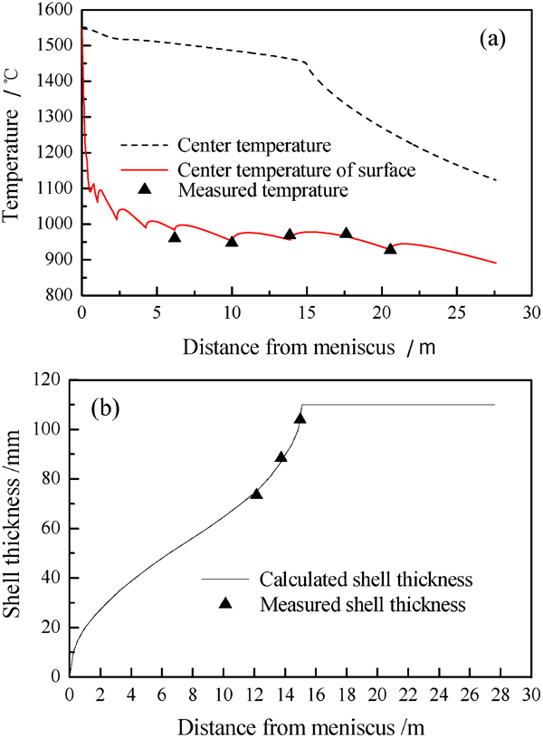
Comparison of predicted and measured a surface temperature and b shell thickness (casting speed, 0·9 m min−1; superheat, 29°C; steel grade, Q420B)
Application of model
Rational control of slab surface temperature
The close relationship between secondary cooling and quality of the slab has been demonstrated extensively. 18 18,19 The rational control of the temperature field of a slab is useful to decrease the stress and strain in a continuous casting process and improves the quality of the slab.
The behaviour of the high temperature mechanical properties of Q420B was tested by a Gleeble 1500 thermal simulator, and the high temperature ductility for the steel is shown in Fig. 5. The value for the reduction in area (RA), used as a basic judgment index for brittle fracture in the high temperature region, was fixed as 80% for Q420B in this study because the Nb bearing steel is very sensitive to cracking. Thus, below 1000°C, there is a significant reduction in ductility, especially when the temperature is between 690 and 880°C, where the value of RA is <30%. In this zone, relatively small deformation of the slab can result in cracking; therefore, it is important to avoid the high temperature brittleness region when setting the target surface control temperature in the secondary cooling zone.
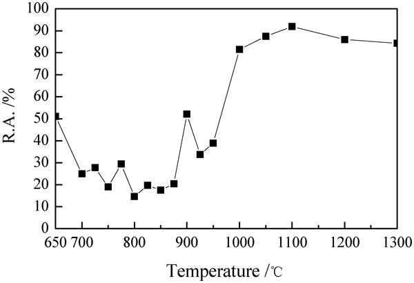
Tendency of reduction of area changed with temperature (steel grade: Q420B, section: 1800×220 mm, casting speed: 0·9 m min−1)
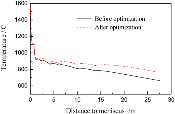
As can be seen from Fig. 6, the model predicted surface temperature of the slab in the straightening zone before secondary cooling optimisation has dropped into the high temperature brittleness region due to the strong cooling intensity. Consequently, the target surface temperature at the straightening zone should be controlled to >1000°C, which is favourable for straightening Nb bearing steel slab. It is clear that the variation of the setting profile of the target surface temperature in Fig. 6 is smooth and slow in the secondary cooling zone. The maximum reheating temperature and the temperature loss are <68 and 179°C m−1 respectively, which obeys the metallurgical rules for surface reheat of <100°C m−1 and a temperature loss of <200°C m−1. 16 16,20
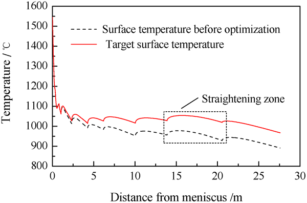
Temperature behaviour of slab surface along casting direction (casting speed, 0·9 m min−1; superheat, 29°C)
The water flowrate in the secondary cooling zones is adjusted according to the temperature difference of the set point between the model predicted values and the desired target values, which increase the water flowrate when the calculated temperature is above the set point, or, alternatively, decreases the water flowrate when the calculated temperature is below the set point. To ensure the rapidity and stability of water adjustment, no changes are made to the water flowrate when the temperature variation is within 5°C. Based on the target surface temperature profile shown in Fig. 6, the water flowrate of each cooling loop can be calculated using the optimisation model for the secondary cooling water flowrate distribution.
Optimised design of secondary cooling spray system
Under the current conditions on CCM2 at the no. 3 steelmaking plant of Hansteel, flat type air mist nozzles are used in the segments, with three nozzles arranged in each row. The distance between adjacent nozzles is 450 mm, and the height from the slab surface to a nozzle is 380 mm. Because the spraying angle is 110°, the water sprayed from the nozzles appears to be triple overlaid on the centre surface of the slab, which causes water accumulation in this region. In addition, the presence of excessive water at the corner of the slab may result in overcooling in the corner region. Uneven cooling along the width direction of the slab can easily lead to slab cracks and other defects.
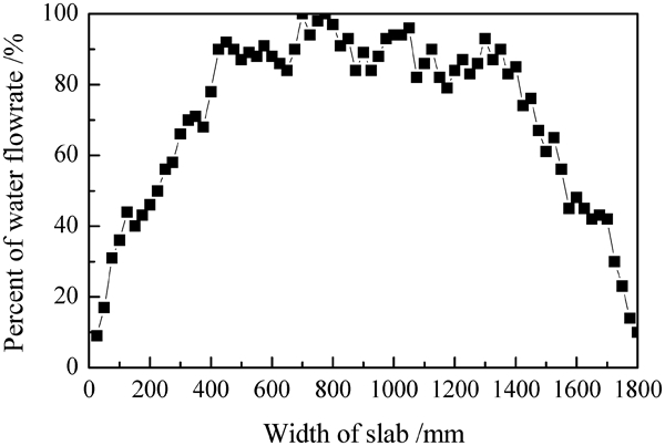
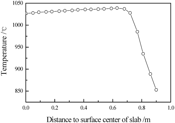
Based on the mathematical model, the stress and strain fields of the slab were also studied under specific casting conditions using the finite element software ANSYS. Considering the symmetry of a slab cross-section, half of the slab cross-section was taken as the research object. Under the current arrangement of nozzles, the distribution of water flowrate in the slab width direction was measured as shown in Fig. 7, and from these data the uneven heat transfer coefficients in the direction were obtained by equation (6). A uniform grid is used for the establishment of the present model, and the heat load conditions are applied to the corresponding surface nodes of the model along the slab width direction. Meanwhile, the adiabatic boundary condition is imposed on the symmetry plane to simulate the solidification and heat transfer in the casting process. Before optimisation at the straightening zone, the temperature profile of the slab surface in the slab width direction was as shown in Fig. 8. As can be seen from the figure, due to the poor spray cooling pattern, there is an uneven surface temperature distribution in the slab width direction. The temperature at the surface centre of slab is only 938°C, while the highest temperature value of the slab surface is 1001°C, which is near the quarter of the whole slab width. Moreover, the lowest temperature of 768°C is at the slab corner.
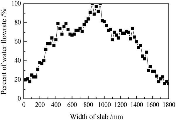
Water distribution along slab width direction before optimisation (water pressure, 0·2 MPa; air pressure, 0·2 MPa)
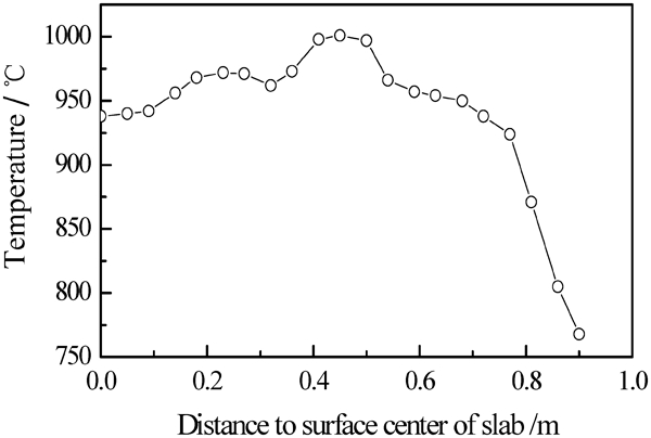
Temperature behaviour of slab surface in slab width direction before optimisation (half section, casting speed, 0·9 m min−1; superheat, 27°C, 18 m below meniscus)
This paper analyses fully the stress field of the slab in the straightening region, between 15·86 and 20·24 m below the meniscus. Because the slab is not fully solidified when the slab enters into the straightening zone, the temperature of the central region of slab is still above the liquidus temperature. In order to simplify the model, the equivalent stress analysis is only focused on the solidified shell. The temperature field before optimisation is set as the initial condition; meanwhile, corresponding ferrostatic pressure is imposed on the solidifying front of the slab for stress analysis. The ferrostatic pressure can be expressed as
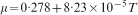
Thermal expansion coefficients
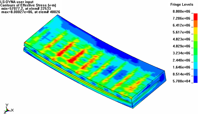
The equivalent stress field of the slab is simulated under the action of the straightening roller along the casting direction, as shown in Fig. 9. The figure shows clearly that the maximum equivalent stress on the slab reaches 8·012 MPa in the straightening zone under the current conditions. Moreover, the stress concentration appears at a quarter of the whole width of the slab and near the slab corner. This may be because the temperature distribution is uneven along the width direction of the slab, which results in a high temperature gradient in the slab. Hence, the corresponding equivalent stresses in these regions are larger than those of the other regions, which can generate easily slab defects.
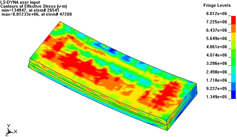
Equivalent stress field of slab at straigthening segment before optimisation (steel grade, Q420B; section, 1800×220 mm; casting speed, 0·9 m min−1; superheat, 27°C)
Uneven cooling usually appears in the width direction of a slab because of its large width. As an additional factor, the heat transfer occurs on two directions at the corner of a slab. Thus, the design scheme for a secondary cooling system should obey the rules of a homogeneous cooling distribution in the width direction and a gradual decrease in the cooling range along the width direction from the top to bottom of the caster; this should prevent defects caused by undercooling in the corner region of the slab. Based on the temperature and stress analysis of the slab, combined with cold test performance data of the nozzles, a new scheme for the secondary cooling system is proposed. This includes the choice and arrangement of nozzles, the calculation of water flowrate in different cooling loops and the optimisation of the water ratio of the inner and outer arcs. The specific water flowrate is decreased from 0·68 to 0·62 L kg−1, and the water ratio of the inner and outer arcs is changed from 1·15 to 1·25 in segments 2 and 3, from 1·4 to 1·55 in segments 4 and 5 and from 1·6 to 1·7 in the other segments. The arrangement of the nozzles is shown in Table 3.
Scheme for selection and arrangement of nozzles*
*These nozzles are produced by Boji Spraying System Co., Ltd, Jiangsu Province, China. The parameters of the nozzles are as follows: 3/8PZ5080B12, where 3/8 is the interface screw thread, PZ is the nozzle, 50 is the flowrate under the standard pressure of 0·3 MPa (L min−1), 80 is the spraying angle under the standard pressure of 0·3 MPa (°), B is the flat type and 12 is the spraying type (expressed in 1, 2, 3, …); and HPZ4·6-90B14, where HPZ is the mixed type nozzle, 4·6 is the flowrate under the standard pressure (the general water and air pressures are 0·2 MPa, L min−1), 90 is the spraying angle under the standard pressure (°), B is the flat type and 14 is the spray type (expressed in 1, 2, 3, …).
After the optimisation, the distribution of the water flowrate in the slab width direction is improved significantly, as shown in Fig. 10, and thus, the corresponding calculated slab temperature profile at the straightening zone is also improved significantly, as shown in Fig. 11. The highest surface temperature is 1040°C, which is only 13°C higher than the surface centre temperature. Meanwhile, because weak (soft) cooling in the corner region of the slab was adopted in the new design scheme of the secondary cooling system, the temperature in the corner region was obviously improved to avoid the quality defects caused by overcooling in the corner of the slab. The results are shown in Fig. 12.
Water distribution along slab width direction after optimisation (water pressure: 0·2 MPa, air pressure: 0·2 MPa)
Temperature behaviour of slab surface in slab width direction at straightening zone after optimisation (casting speed, 0·9 m min−1; superheat, 27°C, 18 m below meniscus)
Comparison of temperature profiles of corner region before and after optimisation of spraying system
On the basis of the optimisation of the temperature field, the stress field of a slab at the straightening zone was analysed. The simulation results for the equivalent stress field in the straightening zone of the slab after optimisation are shown in Fig. 13. Comparison of Figure 9 Figs. 9 and 13 shows that although the maximum values of equivalent stress decrease from 8·012 to 8·000 MPa after optimisation (only reduced by 0·012 MPa), the stress concentration has almost disappeared. The larger stresses shown in Fig. 13 exist only where the slab and the rollers are in contact because of the ferrostatic pressure of the molten steel. However, a wide range of slab surface was under the state of large equivalent stress before optimisation, which was harmful to the surface quality of the slab. In the software simulation, the temperature and stress fields were both greatly improved, which helped to improve the quality of the slab.
Equivalent stress field of slab at straigthening segment after optimisation (steel grade, Q420B; section, 1800×220 mm; casting speed, 0·9 m min−1; superheat, 27°C)
Comparison of slab quality before and after optimisation
After the optimisation of the secondary cooling spray system, the quality of the Q420B ship plate steel was greatly improved. Slab microstructure photos before and after optimisation are shown in Figure 4 Figs. 14 and 15 respectively. Before optimisation, the cooling intensity in the inner arc was larger than that in the outer arc and promoted the growth of columnar crystals. As can be seen in Fig. 14, there was a very uneven distribution of equiaxed crystals between the inner and outer arcs. The width of the equiaxed grain zone was ∼32 mm in the outer arc, but there were no equiaxed grains in the inner arc region. In addition, heavy centreline macrosegregation was seen at the centre of the slab.
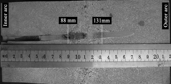
Pin shooting sampling macrostructure graph of slab at outlet of no. 5 segment (casting speed, 0·9 m min−1; superheat, 29°C; steel grade, Q420B)
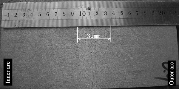
Microstructure photo of internal quality of slab after optimisation (casting speed, 0·9 m min−1; superheat, 27°C)
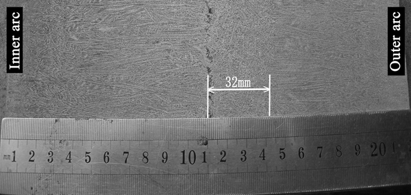
Microstructure photo of internal quality of slab before optimisation (casting speed, 0·9 m min−1; superheat, 27°C)
Figure 15 shows that the ratio of equiaxed grains increased from 14·55 to 17·73% after optimisation, and the distribution of the equiaxed grains on the two sides became uniform. This indicates that the cooling of the two sides of the slab is more uniform after optimisation. In addition, the centreline macrosegregation was also reduced. The results of a statistical analysis of transverse cracks on the surface of the slab also show that the quality of the steel is greatly improved. The transverse cracking disappeared after optimisation compared to a ratio of ∼4·3% before optimisation.
The quality of the ship plate steel was greatly improved after optimisation of the secondary cooling system.
Conclusions
On the basis of a mathematical model of solidification and heat transfer during the continuous casting of slab combined with the process parameters, a simulation software was developed using Delphi 7·0. The model was verified using pin shooting and temperature measurement experiments during the casting of Q420B steel slab. Comparison of shell thickness and surface temperature measurements indicated that the relative error was 1·69%, which indicated that the model was reliable.
The temperature field and the shell thickness were calculated by the software. Based on different steel grades, the distribution of the surface temperature was controlled to acquire an appropriate water flowrate for each loop of the secondary cooling segments. It was found that increasing moderately the temperature at the corner of a slab and obtaining a more uniform temperature field for the slab would help to improve its quality.
On the basis of the heat transfer model, the stress field at the straightening zone of a slab was analysed by ANSYS. A comparison of the stress fields before and following optimisation of the secondary cooling was carried out, which provided the theoretical basis for the optimisation of the secondary cooling system.
After optimising the secondary cooling system for the CCM2, the results of an experiment showed that the quality of the steel was greatly improved. The centreline macrosegregation was reduced, and the ratio of the region of equiaxed crystals was increased by 3·18%. Meanwhile, the cooling of the two sides became uniform, and the transverse cracking disappeared.
Footnotes
Acknowledgements
The authors are grateful for the grants received from the New Century Excellent Talents Program of the Ministry of Education, China (grant no. NCET07-0067) and the National Natural Science Foundation (grant no. 51074023).