
Abstract
Cold rotary forging is an advanced and very complex incremental metal forming process with multifactor coupling interactive effects. Previous research is mainly based on experimental and analytical methods and thus cannot provide full details on the deformation characteristics and mechanisms of cold rotary forging. In the current work, a decisive factor in cold rotary forging, namely equivalent feed amount per revolution 


Introduction
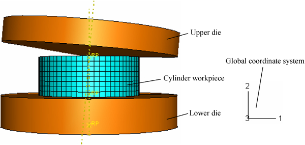
Cold rotary forging is an advanced incremental metal forming process that has wide application in many industry fields, such as automobile, machine tool, electrical equipment, cutting tool and hardware. During the cold rotary forging process (shown in Fig. 1), the upper die continuously oscillates around the vertical machine axis. Simultaneously, the lower die pushes the workpiece vertically so as to cause it to be subjected to axial compression. Thus, after the workpiece is pressed repeatedly several times, the plastic deformation will be completed perfectly. The advantages of cold rotary forging include reduced noise and vibration, uniform quality, smooth surface, close tolerance and considerable savings in energy and materials cost.
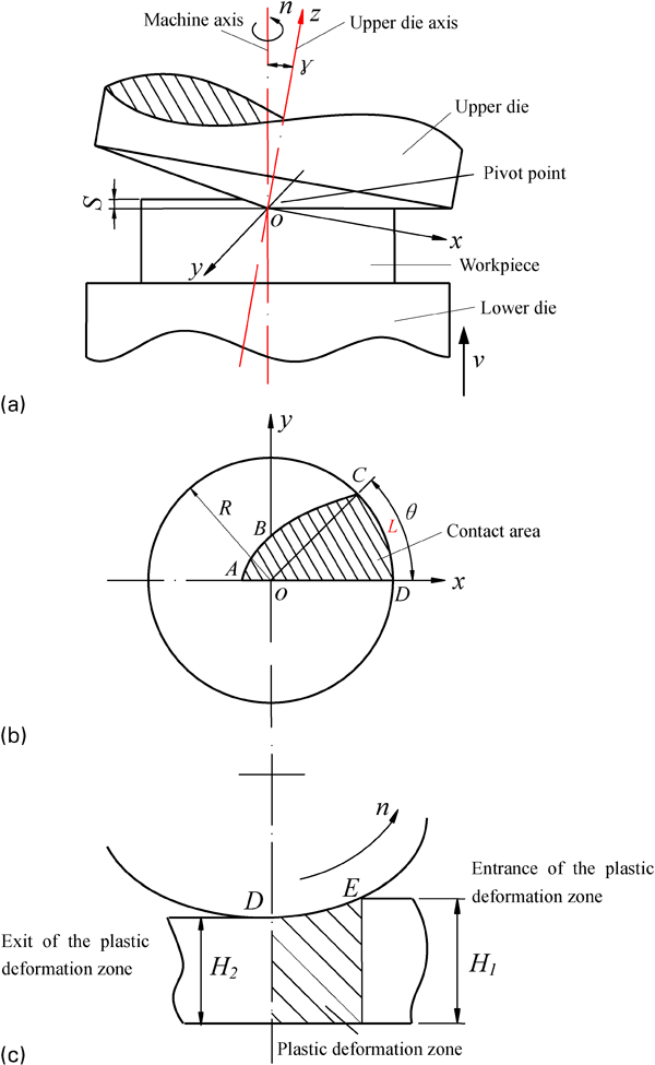
Schematic diagram of cold rotary forging of cylindrical workpiece
Up to now, many scholars have carried out research on the cold rotary forging process. These researches mainly focused on measuring the pressure distribution at the contact area, 1 1,2 calculating and verifying the power parameters3 – 6 and analysing the metal flow7 – 16 by analytical and experimental methods. However, it is very difficult to obtain satisfactory results because of the limit of these methods. The finite element (FE) method has been proven to be a good method in analysing the metal forming process. However, the existing FE research on cold rotary forging17 – 21 is mainly based on rigid plastic theory, so it is difficult to obtain acute simulation results because the elastic deformation has an important effect on the cold rotary forging process. Moreover, these FE researches have not been able to provide full details on the deformation characteristics and mechanisms of cold rotary forging. Therefore, it is urgent to reveal the deformation characteristics and mechanisms of cold rotary forging by the elastic–plastic FE method. As described above, cold rotary forging is a complex incremental metal forming process under coupled effects with multiprocessing parameters, such as geometry sizes of the workpiece, feedrate of the lower die, rotational speed and inclination angle of the upper die, etc. Consequently, the results of studying any single processing parameter cannot reflect the deformation characteristics and mechanisms of cold rotary forging comprehensively. Therefore, a comprehensive and decisive factor, including multiprocessing parameters, has to be determined and presented so as to thoroughly reveal the deformation mechanisms of cold rotary forging.
Consequently, in this study, a decisive factor, namely equivalent feed amount per revolution 


Determination of decisive factor in cold rotary forging
Definition and significance of equivalent feed amount per revolution Q
In the metal plastic forming process, the shape and size of the plastic deformation zone have a decisive effect on the forming process, such as metal flow, degree of inhomogeneous deformation of workpiece and force and power parameters. In this paper, based on the deformation characteristics of cold rotary forging, the length/height ratio of the plastic deformation zone K is put forward to describe the plastic deformation zone.
As shown in Fig. 1c
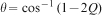
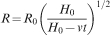
, the shadow region is just the plastic deformation zone. The length/height ratio of the plastic deformation zone K is defined as
The length L of the plastic deformation zone is defined as the axial projection length of the contact arc DE between the upper die and the cylindrical surface of the cylindrical workpiece, as shown in Fig. 1c
. Obviously, arc DC shown in Fig. 1b
is the axial projection arc of the contact arc DE. Thus, L can be obtained according to the geometric relationship shown in Fig. 1b

The value of ∠COD can be expressed by3
By substitute equations (2)–(4) into equation (1), we have
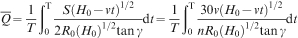
Determination of mathematical expression of equivalent feed amount per revolution
However, it can be seen from equation (4) that for a given cold rotary forging process, Q is an instantaneous variable changing with time. Therefore, its average value over the total forming time T, namely 
By substituting equation (6) into equation (4), we have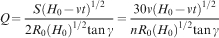

Determination of reasonable range of

In cold rotary forging, the value of 

In cold rotary forging, the surface of the upper die is a conical surface, so the upper die contacts the workpiece only partially; otherwise, the cold rotary forging process has become the conventional forging. Therefore, according to the geometric relationship shown in Fig. 1b
, we have


Three-dimensional (3D) FE modelling of cold rotary forging
Based on the forming characteristics, a reliable 3D FE model of cold rotary forging of a cylindrical workpiece is developed under the ABAQUS/Explicit software environment, as shown in Fig. 2. Summarily, the proposed model has the following features:
Three-dimensional FE model of cold rotary forging of cylindrical workpiece
because the elastic deformation that occurs in the cylindrical workpiece has a significant effect on the cold rotary forging process, the elastic–plastic FE method is adopted to improve the computational accuracy
the dynamic explicit FE procedure is used to avoid the huge computation time and convergence problem of the static implicit procedure
the upper and lower dies are defined as 3D analytical rigid bodies, while the cylindrical workpiece is defined as a 3D deformable solid body. The contact between the dies and the cylindrical workpiece is defined as surface to surface contact type, which allows sliding between the surfaces. The finite sliding formulation is adopted to account for the relative motion of two surfaces. Additionally, the relative sliding that exists between the dies and the cylindrical workpiece contributes to describe the friction condition of the contact pairs with a Coulomb friction model
the rigid motion of the rigid bodies in all degrees of freedom can be represented by the reference point, as shown in Fig. 2. The upper die is constrained to rotate only around the global two axis, while the lower die is constrained to translate only along the global two axis. Because of the oscillation of the upper die, the cylindrical workpiece may rotate together with it during the cold rotary forging process. Based on the deformation characteristics, the constraint type ‘distributing coupling’ is adopted to constrain the rotation of the cylindrical workpiece
in the cold rotary forging process, the contact surface between the upper die and the cylindrical workpiece is a portion of an Archimedes spiral surface. Thus, after the lower die stops the axial feed, the upper die still has to oscillate at least one revolution around the machine axis so as to make the upper surface of the cylindrical workpiece become a plane. The load curves of the upper and lower dies are shown in Fig. 3
the 3D linear reduction integration continuum element with eight nodes (C3D8R) is used to discretise the cylindrical workpiece. The number of elements in the cylindrical workpiece is determined by its size and computational efficiency and precision, and the adaptive mesh technology is employed to reduce the distortion of the elements
mass scaling technology is adopted in the simulation process; appropriate mass scaling factors are selected to improve the computation efficiency while the computational accuracy is also satisfied.
Load curves of upper and lower dies
Verification of developed 3D FE model of cold rotary forging
In order to validate the proposed 3D FE model, experiments have been carried out on a T 200 cold rotary forging press at Hubei Automobile Axle Co., Ltd, China, as shown in Fig. 4. The processing parameters adopted in the simulation and experiment are shown in Table 1. The workpiece material used in this model is AISI 1020, and its mechanical properties are shown in Table 2. Figure 5 shows the initial blank and deformed cylindrical workpiece in the experiment. Figure 6 shows the comparison of the upper surface diameter of the cylindrical workpiece between simulation and experimental results. It can be seen from Fig. 6 that the simulation results are in good agreement with the experimental ones and that the maximum relative error is 3·76%. Thus, the 3D elastic–plastic dynamic explicit FE model of cold rotary forging is proved to be reliable experimentally, and further investigation can be carried out using the developed 3D FE model.
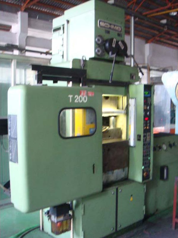
T 200 cold rotary forging press
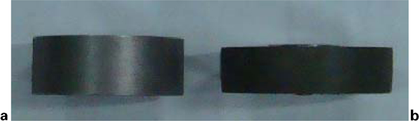
a initial blank and b deformed cylindrical workpiece in experiment
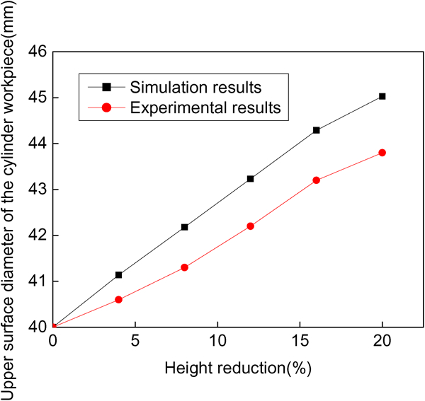
Comparison between simulation and experimental results
Processing parameters adopted in simulation and experiment
Mechanical properties of cylindrical workpiece
Results and discussion
Calculation conditions
From equation (8), it can be seen that if the initial dimensions of the cylindrical workpiece are selected, the value of 

Condition 1: Select v = {0·2, 0·3, 0·6, 1, 2, 3, 4} (mm s−1), n = 300 rev min−1 and γ = 2°, while keeping the other processing parameters listed in
Table 1
Tables 1 and 2 unchanged. The corresponding values of 


Condition 2: Select n = {75, 100, 150, 300, 500, 1000, 1500} (rev min−1), v = 1 mm s−1 and γ = 2°, while keeping the other processing parameters listed in
Table 1
Tables 1 and 2 unchanged. The corresponding values of 


Condition 3: Select γ = {0·5, 0·67, 1, 2, 3·3, 6·5, 10} (°), v = 1 mm s−1 and n = 300 rev min−1, while keeping the other processing parameters listed in
Table 1
Tables 1 and 2 unchanged. The corresponding values of 


Characteristics of distribution of plastic deformation zone
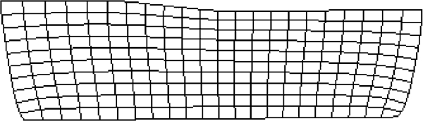
Figure 7 shows the equivalent plastic strain (PEEQ) distribution in the axial section of the cylindrical workpiece during the cold rotary forging process. At the early stage of the process, the plastic deformation zone is formed first at the central region of the upper surface of the cylindrical workpiece, as shown in Fig. 7b . With increasing height reduction ΔH/H 0, the plastic deformation zone gradually develops axially towards the lower surface of the cylindrical workpiece, as shown in Fig. 7c . When ΔH/H 0 = 15·94%, the plastic deformation zone penetrates the axial height at the region near the cylindrical surface, as shown in Fig. 7d . When keeping on increasing ΔH/H 0, the entire axial height has been penetrated completely by the plastic deformation zone, as shown in Fig. 7e . From the above analysis, it can be concluded that the PEEQ distribution exhibits a transfer characteristic from the upper surface to the lower surface of the cylindrical workpiece. Figure 8 shows the selected viewpoints and the variation curves of their PEEQ with time. From Figure 7 Figs. 7 and 8, it can be seen that the plastic deformation of the metal of the upper region is larger than that of the lower region at any time of the cold rotary forging process. Therefore, the deformed cylindrical workpiece exhibits the ‘mushroom’ effect (shown in Fig. 7), which is the main deformation characteristic of cold rotary forging.
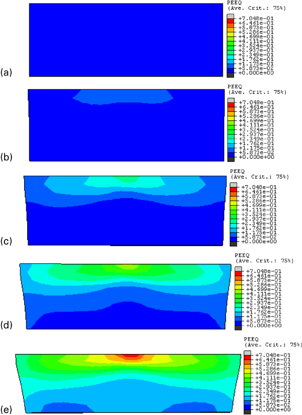
Equivalent plastic strain distribution in axial section of cylindrical workpiece
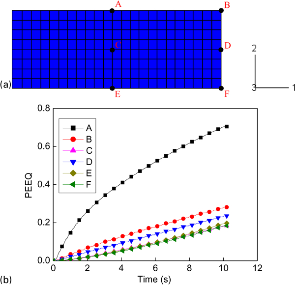
Selected view points and variation curves of their PEEQ with time
Effect of

on plastic penetrating states
From the distribution of the plastic deformation zone shown in Fig. 7, it can be concluded that cold rotary forging is a plastic penetrating process in which the plastic deformation zone gradually penetrates the axial height of the cylindrical workpiece from the upper surface to the lower surface. According to the slip line field theory, the depth of the plastic deformation zone increases with increasing length of the plastic deformation zone. As for cold rotary forging, the larger the length/height ratio of the plastic deformation zone K, the more easily the plastic deformation zone can penetrate the axial height of the cylindrical workpiece from the upper surface to the lower surface, and vice versa. Through a comprehensive analysis and summary, it is found that there exists three different plastic penetrating states in cold rotary forging under different 
when the value of 
when the value of 
when keeping on increasing the value of 

Effect of
Effect of

on metal flow
In cold rotary forging of the cylindrical workpiece, the axial flow of the metal leads to the reduction in axial height, while both radial and circumferential flows of the metal result in the expansion in diameter. Under the same reduction amount in the axial height, the geometric dimensions and shape of the deformed cylinder workpiece may be different under different 


Definition of growth rate of upper surface diameter

The effect of 


Effect of
It can also be seen from Fig. 11 that the effect of 


Effect of

on degree of inhomogeneous deformation of cylindrical workpiece
According to an instability theory of fracture, ductile fracture will never occur in a homogeneous deformation. However, if the deformation becomes very inhomogeneous, the fracture will develop. Meanwhile, the deformation inhomogeneity has a significant influence on the microstructure inhomogeneity, thus affecting the properties of the deformed parts. In this paper, the difference between the maximum and minimum PEEQ is adopted to represent the degree of inhomogeneous deformation of the deformed cylindrical workpiece, namely φ
id = ϵ
max−ϵ
min. The larger φ
id is, the more inhomogeneous the deformation of the cylindrical workpiece is, and vice versa. Figure 12 illustrates the effect of 


Effect of
From Fig. 12, it can also be found that the effect of 


It can be concluded from the above analysis that it is the inhomogeneous deformation that results in the occurrence of the ‘mushroom’ effect of the cylindrical workpiece. However, the ‘mushroom’ effect has duality. In the riveting process, the ‘mushroom’ effect can be utilised to realise the loose and tight riveting. With increasing 


Effect of

on force and power parameters
Figure 13 illustrates the variation curves of the axial forging force and forging moment during the cold rotary forging process. It can be seen from Fig. 13 that the cold rotary forging process has experienced three forming stages. At the first stage, the upper die begins to contact the cylindrical workpiece. Therefore, the axial forging force and forging moment increase rapidly from zero to a certain value. At the second one, the axial forging force and forging moment increase slowly up to their maximum values, indicating that the process has entered the steady forming stage. At the end of the process, because the lower die stops the axial feed while the upper die still oscillates so as to make the upper surface of the cylindrical workpiece become a plane, the axial forging force and forging moment decrease rapidly. Additionally, it can also be seen from Fig. 13 that the axial forging force and the forging moment oscillate with time. This is because cold rotary forging is a complex dynamic contact, highly non-linear and non-steady state deformation process.
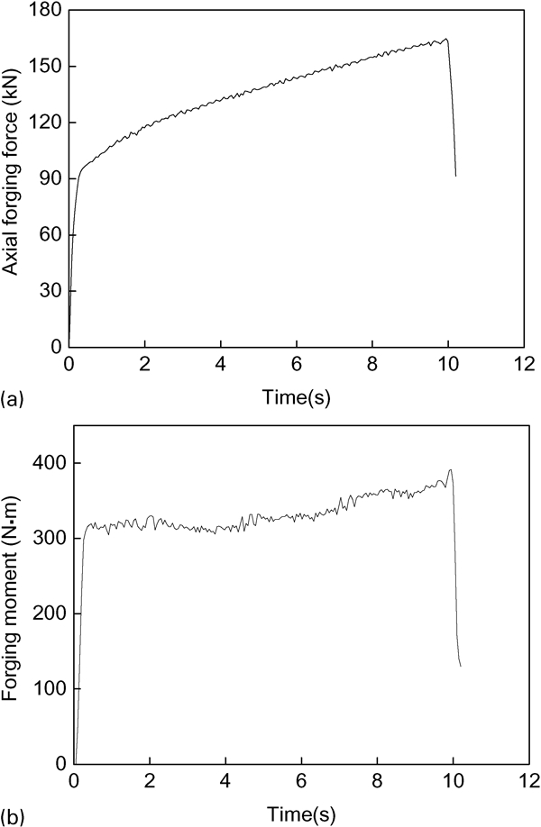
Variation curves of a axial forging force and b forging moment with time
Figure 14 provides the effect of 


Effect of
It can also be seen from Fig. 14 that the effect of 


Conclusions
In this paper, a decisive factor in cold rotary forging, namely, equivalent feed amount per revolution 

The equivalent feed amount per revolution 
There exists three different plastic penetrating states in cold rotary forging under different 


With increasing 


The results of this research thoroughly reveal the deformation characteristics and mechanisms of cold rotary forging of a cylindrical workpiece and help to optimise the processing parameters so as to precisely control the cold rotary forging process.
Footnotes
Acknowledgements
The authors would like to thank the Natural Science Foundation of China for Distinguished Young Scholars (grant no. 50725517), Natural Science Foundation of China (grant no. 51105287) and State Key Laboratory of Materials Processing and Die & Mould Technology, Huazhong University of Science and Technology (grant no. 2011–P05) for the support given to this research.