
Abstract
Based on the careful analysis of the heat transfer mechanism of the cooling process of high temperature sinter, a one-dimensional unsteady state mathematical model for the gas–solid heat transfer process of high temperature sinter was established according to the energy conservation. The mathematical model was verified by the use of industrial practical data, and the results showed that it was correct and reliable. Lastly, the model was used to investigate the effect of operation parameters (such as the trolley moving speed and the cooling air velocity) on the cooling process of the annular cooler, and the proposals were put forward for optimising operations of the annular cooler.
Introduction
In recent years, the iron and steel industry, which is a high energy consumption and high polluting industry, has made rapid developments. Research 1 1,2 has shown that the sintering process accounts for nearly 10% of the total energy consumption of the whole iron and steel industry, and thus, is the second largest energy consuming process. In addition, up to 50% of the thermal energy is taken away by the sintering flue gas and the waste cooling gas of the sintering process. Waste heat from the main flue gas in the sintering bed accounts for 13–23% of the total sintering energy consumption, and waste heat of the sinter cooling machines (the annular cooler or the belt cooler) accounts for 19–35%. This is not only a waste of resources but also causes the environmental pollution. In this paper, by studying the heat transfer mechanism of the cooling process of high temperature sinter in the annular cooler, a one-dimensional (1D) unsteady state mathematical model for the gas–solid heat transfer process of high temperature sinter was established to clarify the high temperature sinter cooling air flowrate, waste hot air flowrate and the temperature variation with time, which provide a guiding basis for better achieving the cascade utilisation of high temperature sinter waste heat. The model has been validated on the basis of practical data gathered in an annular cooler (Fig. 1), and on the basis of the model predictions, proposals are put forward for optimising operations of the annular cooler.
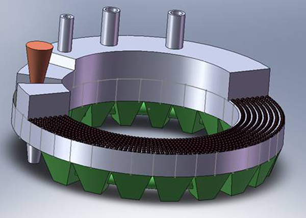
Schematic of annular cooler used in study
Thermal model of sinter cooling
Once the sintering process is complete, the high temperature sinter falls on the cooling bed. Depending on the running condition, the average temperature of the sinter at the inlet of the cooling bed varies from 700 to 800°C. Cooling of the moving beds is usually achieved by blowing fresh air from below the bed. Some of the heated air (∼300°C) may be collected by one or more hoods to be used as the heating medium for the waste heat recovery system. After cooling on the bed, the sinter is <150°C.
Physical model
Figure 2 shows the physical configuration used in the model. The high temperature sinter, which is in the moving bed in the annular cooler, is considered as a uniform porous medium confined in a rectangular region that moves from left to right and the cooling air flows from bottom to top. The following assumptions and simplifications were made for the annular cooler system before establishing the model:3 – 5
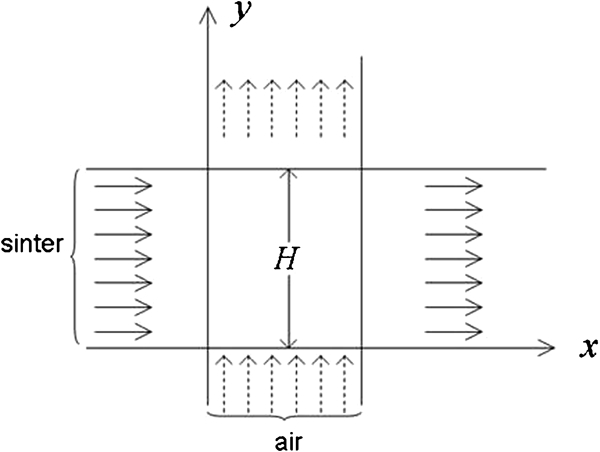
Physical configuration used in model
the annular cooler system is operated in a stable condition and the porous medium is homogeneous and isotropic
the heat transfer process between sinter and gas is stable
sinter in the annular cooler moves horizontally from left to right, and air moves vertically from bottom to top
the internal thermal conductivity along the ‘y’ direction is only considered
the relative velocity between the air and sinter is the air velocity
the thermal conductivity of the gases is negligible.
Mathematical model
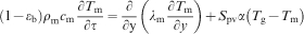
Under the above assumptions, the gas and solid energy balance equations about the cooling process of high temperature sinter are as follows.6 – 8
Gas equation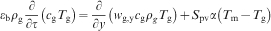
Conditions for modelling
Initial conditions
Where τ = 0, 
At the entrance to the annular cooler where the sinter is falling, we assume that the temperature of the solid in the height direction is the initial temperature of the sinter when it falls into the annular cooler and the gas temperature is ambient temperature.
Boundary conditions
Where y = 0, 
The air inlet temperature is ambient temperature at the bottom of the annular cooler.
Numerical methods
The calculation core of the above model is to solve the 1D unsteady heat transfer equation. In this paper, the control equation is discretised in space by finite difference technique (differential equations are transformed into discrete node algebraic equations). On the basis of the boundary conditions, sinter and gas temperature variation with time at spatial discrete points can be obtained by the time division multiple access method.
Mathematical model verification
The mathematical model should be validated by practical data. The numerical simulation on the cooling process of sinter in the annular cooler is studied in this paper, and the simulated results are compared with the measured data from the sinter plant. Table 1 shows the main parameters of the annular cooler used in the calculation, and Table 2 shows the comparison of computed and measured sinter temperature of the upper surface. Figure 3 shows the sinter temperature on the upper surface along the moving cooling bed. According to Table 2 and Fig. 3, the calculated temperature of the sinter surface shows a good agreement with the measured data, and the maximum relative error is 4·79%; this indicates that the model is correct and credible.
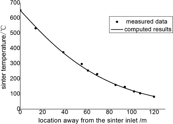
Comparison of predicted and measured sinter temperature on upper surface along moving cooling bed
Main parameters of annular cooler used in calculation
Comparison of computed and measured sinter temperature on upper surface
Results analysis and discussion
Based on the above validated mathematical model, the effects of cooling air velocity, trolley’s moving speed, sinter size and void fraction on the cooling process of high temperature sinter are studied here.
Results analysis
Figure 4 shows that the sinter temperature on the upper surface changes along the moving cooling bed. When the distance from the sinter inlet increases, the sinter temperature on the upper surface decreases because the sinter on the moving trolley is influenced by the cooling air. The figure shows that the sinter temperature is lower than 150°C at the end of cooling, which is consistent with process requirements of sinter cooling.
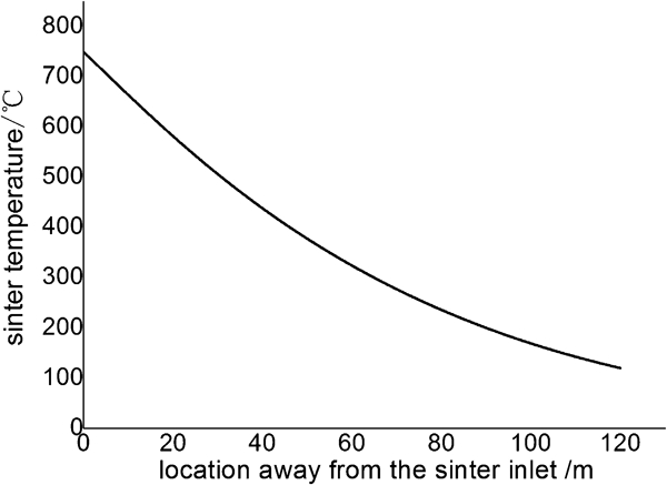
Predicted change in sinter temperature on upper surface along moving cooling bed
Figure 5 shows that air temperature and air velocity on the upper surface change along the moving cooling bed. Figure 5a shows numerical result in this paper, and Fig. 5b shows numerical results in Ref. 8; the results are in close agreement. When the distance from the sinter inlet increases, the air temperature and air velocity on the upper surface decrease because cooling air temperature increases by absorbing the heat from the high temperature sinter as the sinter temperature decreases. According to the Fig. 4, the sinter temperature decreases gradually along the moving bed, which leads to the decrease in cooling air temperature along the moving bed. For the same initial standard air velocity, the actual air velocity on the upper surface is determined by the air temperature; with air temperature decreasing, the air velocity decreases.

Predicted change in air temperature and air velocity in upper surface of sinter along moving cooling bed
Effect of cooling air velocity on cooling process of high temperature sinter
As shown in Fig. 6, with the increase in the cooling air velocity, the sinter outlet temperature tends to decline. When the air velocity increases by 0·1 m s–1, the temperature drops by ∼20°C. This is because when air velocity increases, the forced convection effect between the cooling air and the sinter leads to a decrease in sinter outlet temperature. In industrial production, since sinter outlet temperature is usually controlled under 150°C, the air velocity should be controlled above 0·9 m s–1. Considering that the drag force and system energy consumption will increase due to the increase in air velocity, the cooling air velocity should be controlled in the range of 0·9–1·2 m s–1.
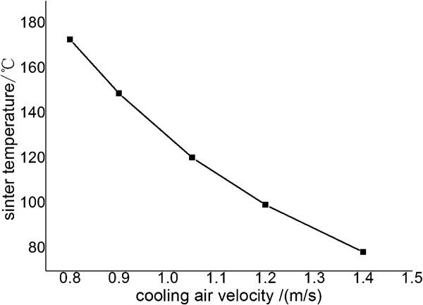
Predicted effect of cooling air velocity on sinter outlet temperature
Effect of trolley’s moving speed on cooling process of high temperature sinter
As shown in Fig. 7, with an increase in trolley speed, sinter outlet temperature increases. When moving speed increases at 0·002 m s–1, the sinter outlet temperature rises by ∼12°C. This is because for the same production output, an increase in trolley’s speed, which leads to shorter cooling time for the sinter and weakening of the cooling effect, thins the sinter bed. This leads to the increase in the cooling effect, but the former is the main factor here; therefore, sinter outlet temperature increases. However, if the trolley’s speed is too slow for the same production output, the sinter bed depth will rise, even more than the height of trolley, which is not in accordance with the actual situation. All in all, considering the two factors above, the speed of the trolley should be between 0·023 and 0·028 m s–1.
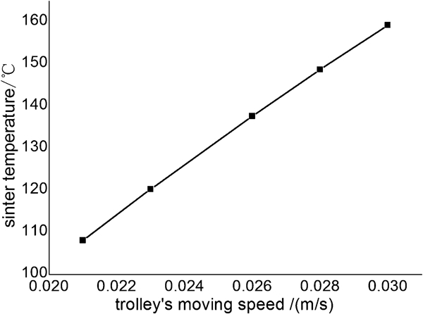
Predicted effect of trolley’s moving speed on sinter outlet temperature
Effect of sinter size on cooling process of high temperature sinter
Figure 8 shows that with an increase in sinter size, the sinter outlet temperature increases; as the sinter size increases by 3 mm, the temperature rises by ∼14°C. Because the heat transfer between high temperature sinter and cooling air is mainly through convection, and with the increase in sinter size, the heat transfer area per unit volume decreases, which makes the effect of the heat transfer between the air and the sinter decline.
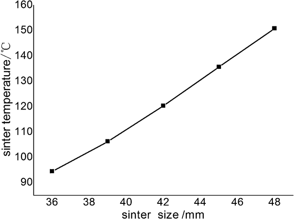
Predicted effect of sinter size on sinter outlet temperature
Effect of sinter void fraction on cooling process of high temperature sinter
As shown in Fig. 9, with the increase in sinter void fraction, the sinter outlet temperature increases. When the sinter void fraction increases by 0·05, the temperature rises by ∼11°C. This is also because the heat transfer between the high temperature sinter and the cooling air is mainly through convection and the heat transfer area per unit volume decreases with the increase in sinter void fraction, which reduces the convection heat transfer between the air and the sinter, making the heat transfer effect decline; therefore, the sinter outlet temperature increases.
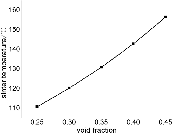
Predicted effect of sinter void fraction on sinter outlet temperature
Conclusions
Based on the careful analysis of heat transfer mechanism of the cooling process of high temperature sinter, a 1D unsteady state mathematical model for the gas–solid heat transfer process of high temperature sinter was developed and the calculating software was developed in Visual Basic language. After ensuring that the model was correct and credible by studying the effects of some thermal parameters of the annular cooler on the cooling process of the sinter, calculations of the effects of the process parameters were undertaken and the conclusions can be summarised as follows.
With an increase in cooling air velocity, the sinter outlet temperature decreased; when air velocity is increased by 0·1 m s–1, the temperature of the sinter dropped by ∼20°C.
With an increase in moving speed of the trolley, the sinter outlet temperature increased; when the moving speed increased 0·002 m s–1, the temperature of the sinter rose by ∼12°C.
With an increase in sinter size, the sinter outlet temperature increased; when sinter size increased by 3 mm, the temperature rose by ∼14°C.
With an increase in sinter void fraction, the sinter outlet temperature increased; when sinter void fraction increased 0·05, the temperature rose by ∼11°C.
When meeting both technological economic requirements at the same time, the cooling air velocity should be controlled in the range of 0·9–1·2 m s–1 and the velocity of the trolley should be maintained between 0·023 and 0·028 m s–1.
Footnotes
Acknowledgements
This work was supported by the National Natural Science Foundation of China (grant no. 50934007).
This paper is part of a special issue on ‘UK: China Steel’