
Abstract
The aim of this work was to analyse the influence of the nozzle structure and parameters on the molten steel flow in beam blank continuous casting. A three-dimensional steady state finite element model was developed to compute the flow field and the meniscus fluctuation in the mould. The volume of fluid model was used to track the free surface evolution at the meniscus. It can be concluded that compared with a through conduit submerged entry nozzle (SEN), a three lateral hole SEN will reduce the impact depth, change greatly the velocity at the free surface and intensify the fluctuation of the free surface. As a whole, the fluid flow in the mould will be improved, which will help to melt the mould powder and improve the absorption of non-metallic inclusions, thus improving steel cleanness. The most rational rake angle for the three lateral hole SEN is 9°. Meanwhile, the SEN immersion depth should be in the range 200–250 mm if the casting speed is about 0·9–1·1 m min−1.
Introduction
The submerged entry nozzle (SEN) is an indispensable device in continuous casting. The SEN structure, the number of ports and their rake angle, and the depth of insertion in the liquid pool influence directly the fluid flow in the mould and consequently the quality of the steel.1, 2 The aim of this work was to analyse the influence of the nozzle structure and parameters on the molten steel flow in beam blank continuous casting. A three-dimensional steady state finite element model was developed to compute the flow field and the meniscus fluctuation in the mould. In order to increase the cleanness of the beam blank, the optimum nozzle structure and parameters are proposed.
Mathematical model
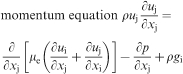
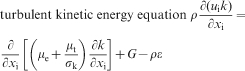
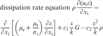
It was assumed that the fluid was an incompressible Newtonian fluid, the flow steady state, the effect of solid shell on the fluid flow could be neglected and the thermal properties of the fluid considered as constants. According to the above hypothesis, the governing equations can be described as follows: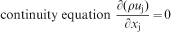
The volume of fluid (VOF) model was used to track the free surface evolution at the meniscus in the mould. The VOF method determines the shape and location of free surface based on the concept of a fractional VOF. A unity value of the volume fraction (VFRC) corresponds to a full element occupied by the fluid and a zero value indicates an empty element containing no fluid or gas. The VFRC value between zero and one indicates that the corresponding element is the partial, or surface, element. The evolution of the free surface is computed, either through a VOF advection algorithm or through the following equation
CLEAR–VOF algorithm is used in this paper. Here CLEAR stands for computational Lagrangian–Eulerian advection remap. This algorithm takes a new approach to compute the fluxes of fluid originating from a home element towards each of its immediate neighbouring elements; these fluxes are referred to as the VFRC fluxes. The idea behind the computation of the VFRC fluxes is to move the fluid portion of an element in a Lagrangian sense and compute how much of the fluid remains in the home element and how much of it passes into each of its neighbouring elements. The typical advection step in CLEAR–VOF is illustrated in Fig. 1.
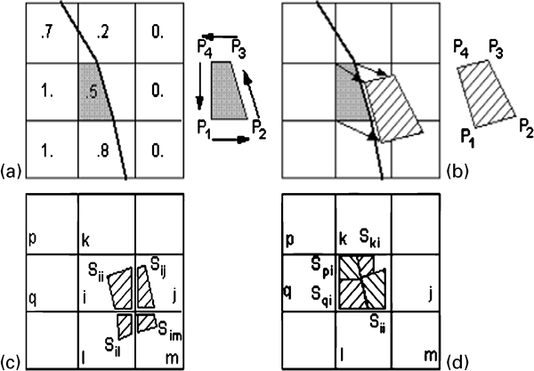
Typical advection step in CLEAR–VOF algorithm
Two different SEN configurations were considered, a through conduit SEN and a SEN with three lateral holes. Figure 2 shows the cross-section of the mould and SEN. In the three lateral hole SEN, one lateral opening faces to the beam blank web and the other two face to the two flange tips respectively. The angle between the three lateral openings is 120°. Figure 3 shows the structure of three lateral holes SEN, where θ is the rake angle between the lateral opening with horizontal direction. The required process parameters are shown in Table 1.
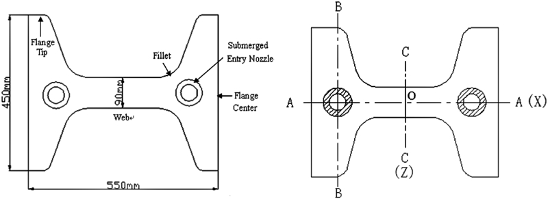
Cross-section of mould and SEN in beam blank continuous casting
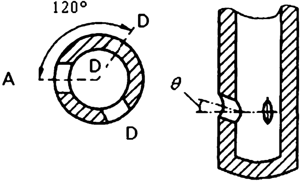
Structure of three lateral hole SEN
Process parameters used in the calculations
Calculated flow field in mould
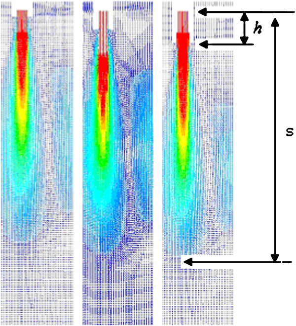
From calculation, it can be concluded that when the through conduit SEN is used, the interfacial oscillations in the mould are relatively small, but the impact depth is too deep, which can produce a negative influence to the melting of the mould powder melting and to the inclusions removal. Figures 4 and 5 show respectively the fluid flow on different sections and the velocity vector at different inserted depths for the through conduit SEN. In order to optimise the flow field in the mould and increase the steel cleanliness, a three lateral hole SEN was researched in this paper. Four different rake angles were analysed, θ = −3, 3, 9 and 15° and the immersion depth was 225 mm. (Note that the immersion depth for the through conduit SEN in the previous work5 was 75 mm.)
Fluid flow in mould with through conduit SEN
Velocity vector at different inserted depth of nozzle with through conduit SEN
Effect of SEN outlet rake angle on flow field
Figure 6 shows on A–O half-section (see Fig. 2) the velocity vector of the molten steel for the different rake angles of the SEN. Figure 7 shows on the D–D section, the velocity vector of the molten steel for the different rake angles. Comparing Figs. 6 and 7 with Figs. 4 and 5, it can be concluded that if the three lateral hole SEN is used, the fluid flow in the mould will change greatly. In the upper part of the mould near the SEN, there exist two vortices near the web and four vortices near the flange. Then, it can be concluded that there are six vortices in the upper mould and six vortices in the lower part. The six vortices in the upper can increase the meniscus fluctuation, which will help to melt the mould powder and the absorption of non-metallic inclusions.
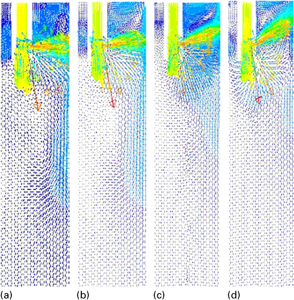
Velocity vector of molten steel on A–A section for three lateral hole SEN
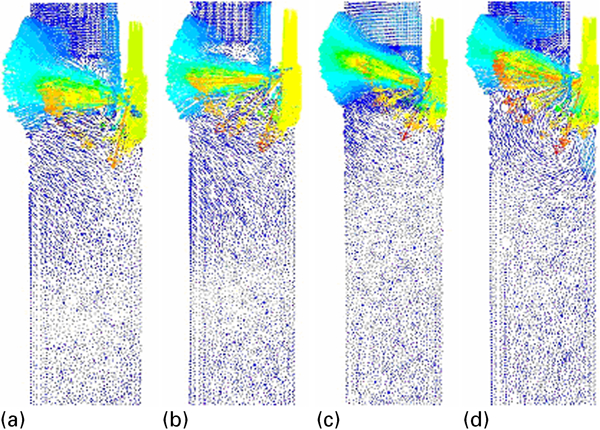
Velocity vector of molten steel on D–D section for three lateral hole SEN
From the calculations, the impact depth(s) of the liquid steel flow at different rake angles θ can obtained; these are 1·03, 0·95, 0·7 and 0·64 m for θ = −3, 3, 9 and 15° respectively. Compared with the impact depth of 1·11 m (immersion depth of 75 mm) with the through conduit SEN, if the three lateral hole SEN is used, the impact depth will reduce greatly. Moreover, with the rake angle increasing, the impact depth will decrease gradually, which will promote the floatation and removal of non-metallic inclusions.
Effect of SEN outlet rake angle on velocity at free surface
The velocity at the free surface with different outlet rake angles is shown in Figs. 8 and 9. It can be seen that with the rake angle increasing, the velocity at the free surface will increase gradually. If the rake angle changes from −3 to 15°, the maximum value of the velocity at free surface near the web will increase from 0·10 to 0·21 m s−1, and near the flange this value will increase from 0·18 to 0·24 m s−1. Moreover, if the rake angle is >9°, the velocity at free surface will change greatly along the flange direction, which implies that at the free surface an obvious fluctuation will appear.
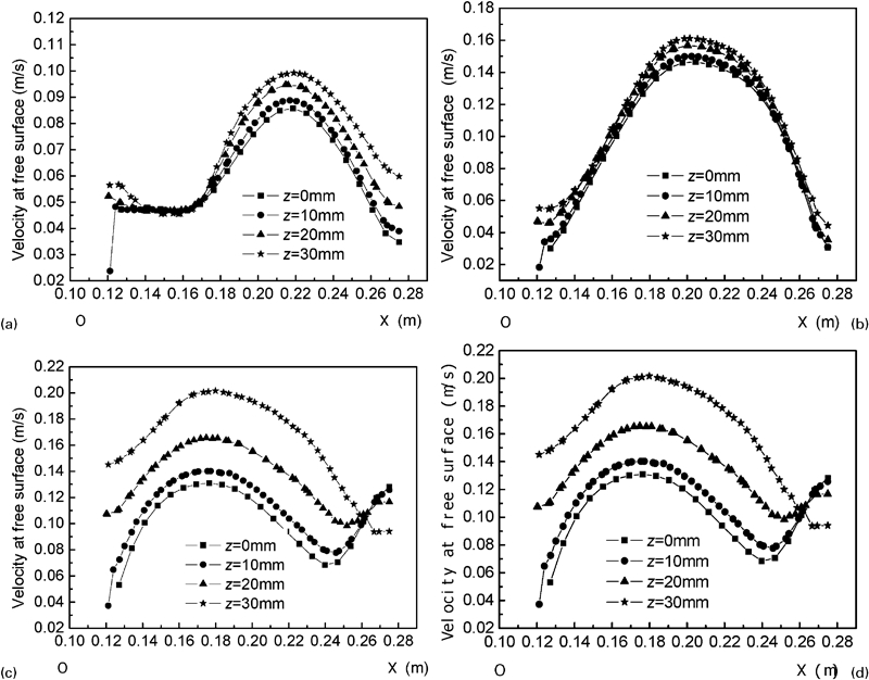
Velocity at free surface near web for different outlet rake angles
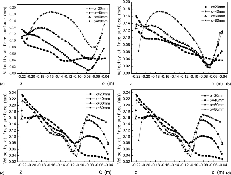
Velocity at free surface neat flange for different outlet rake angles
Effect of SEN outlet rake angle on fluctuation of free surface
The effect of the SEN outlet rake angle on the fluctuation of the free surface was analysed. Figures 10 and 11 show the position tracking of the free surface with different outlet rake angles at a certain time near the web and near the flange respectively. From Fig. 10, the maximum oscillation amplitude O of the free surface near the web can be obtained at different rake angles θ; these are 3·6, 4·1, 5·0 and 5·3 mm respectively for θ = −3, 3, 9 and 15°. From Fig. 11, the maximum oscillation amplitude O near the flange can also be obtained; these are 3·3, 3·6, 4·1 and 6·9 mm respectively for θ = −3, 3, 9 and 15°. Therefore, with the rake angle increasing, the fluctuation of the free surface will intensify gradually.
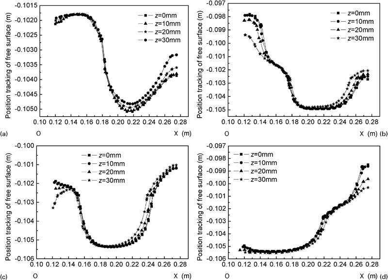
Position tracking of free surface near web for different outlet rake angles
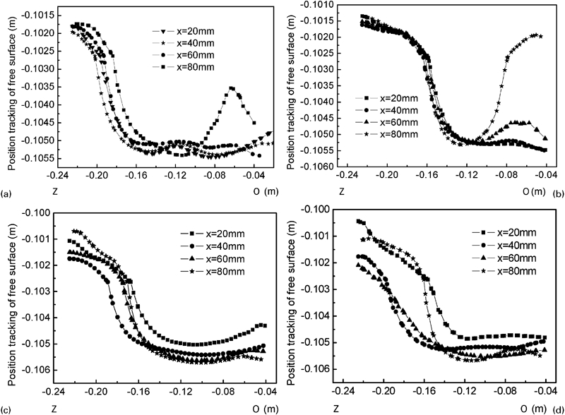
Position tracking of free surface near flange for different outlet rake angles
Comparison of through conduit SEN with three lateral hole SEN
In summary, when the data for the three lateral hole SEN are compared with those of the through conduit SEN:
The three lateral hole SEN will reduce the impact depth. For example, with the three lateral hole SEN with a rake angle of 9°, the impact depth is 0·7 m, compared with 1·11 m for the through conduit SEN.
The velocity at free surface will increase greatly. For example, with the three lateral hole SEN the near the flange the velocity at the free surface is in the range of 0·18 to 0·24 m s−1, but with the through conduit SEN the value is 0·09 to 0·018 m s−1.
The fluctuation of the free surface will intensify. For example, with the three lateral hole SEN, along the flange direction the maximum oscillation amplitude at the free surface is 4·1 mm for a rake angle of 9°, but with the through conduit SEN this value is 2·2 mm when the immersion depth is 75 mm.
Therefore, with the three lateral hole SEN the whole fluid flow in the mould will improve, which will help to mould powder to melt, absorb non-metallic inclusions, and then improve the cleanness of the steel.
But, which rake angle of the SEN is the best for the quality of the beam blank? According to the calculations, if the angle is <3°, the impact depth will be greater than the mould length of 700 mm. Moreover, near the web, the maximum oscillation amplitude of the free surface is <3·6 mm and near the flange the maximum oscillation amplitude is <4·1 mm. Thus, the meniscus fluctuation is relatively steady. But if the angle is >15°, near the web the maximum oscillation amplitude of the free surface is >5·3 mm, and near the flange the maximum oscillation amplitude is >6·9 mm, so the meniscus fluctuation is relatively severe.
According to the production experience of continuous casting, the reasonable oscillation amplitude of the free surface is about 3–5 mm. Based on mass calculation, the most rational rake angle for the three lateral hole SEN is 9°. Meanwhile, the inserted depth of SEN should be in the range 200–250 mm if the casting speed is about 0·9–1·1 m min−1.
Water model experiments
In order to test and verify the simulation results, water model experiments were carried out using a mould made from polymethyl methacrylate. To obtain a fully developed fluid flow the mould length was 1·2 m, thus greater than the actual value. A cellular dummy plate was installed above the bottom of the mould in order to reduce the effect of the water outlets on the fluid flow. The experimental system consists of the water equipment, the mould and the test instrumentation and this is shown in the schematic of the set-up in Fig. 12.
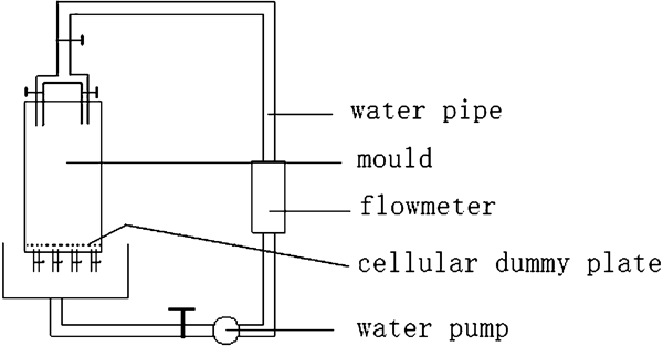
Schematic of water modelling experimental equipment
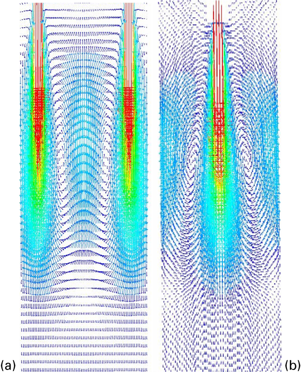
Figure 13 shows the fluid flow field in the mould of the beam blank with the through conduit SEN at 0·98 m min−1 casting speed and 75 mm immersion depth of SEN. Figure 14 shows the fluid flow field for the three lateral hole SEN at 225 mm immersion depth. Table 2 compares the results from the calculations and water model experiments. It can be seen that the fluid flow characteristics from the calculation are very similar to the water model experiments.
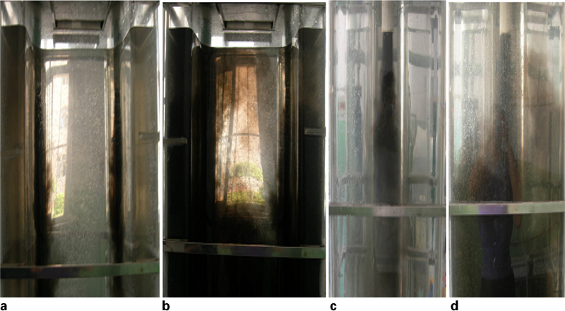
Fluid flow in mould with through conduit SEN
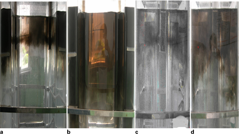
Fluid flow in mould with three lateral hole SEN
Parameters comparison between calculation and water modelling experiment
The results from this research project have been applied gradually to a production caster. The optimum immersion depth of the nozzle, the rational casting speed and the optimum three lateral hole SEN have been adopted in production. Moreover, other research results have been used, such as hot metal desulphurising, optimising the turbulence inhibitor in the tundish, modifying water consumption in secondary cooling zone, etc. Subsequently, the probability of surface cracks has been reduced gradually from 5 to 0·5%. Also, the research has proved that the modified SEN practice is very useful and efficient in the control of steel cleanness.
Conclusions
In the present paper, a three-dimensional steady state finite element model was developed to compute the flow field and the meniscus fluctuation in the mould of beam blank continuous casting and then to analyse the influence of the nozzle structure and parameters on the fluid flow of the molten steel. The following conclusions can be drawn.
If the through conduit SEN is used, the interfacial oscillations in mould is relatively small and the impact depth is too deep, which can bring negative influence to the mould powder melting and the removal of non-metallic inclusions.
If the three lateral hole SEN is used, the fluid flow in the mould changes greatly. There are six vortices in the upper mould and six vortices in the lower part. The six vortices in the upper part can increase the fluctuation of the meniscus, which will helps to melt the mould powder and absorb non-metallic inclusions.
Comparison of the three lateral hole SEN with the through conduit SEN shows that if three lateral hole SEN is used the impact depth will reduce, the velocity at free surface will change greatly and the fluctuation of the free surface will intensify. Therefore, the fluid flow in the mould will become better, which will help to melt the mould powder and absorb non-metallic inclusions, and thus improve the cleanness of the steel.
The most rational rake angle for the three lateral hole SEN is 9°. Meanwhile, the immersion depth of SEN should be in the range 200–250 mm if the casting speed is about 0·9–1·1 m min−1.
Footnotes
Acknowledgements
The authors would like to acknowledge the financial support provided by Natural Science Foundation of Hebei Province.