
Abstract
Mathematical modelling of both fluidised and packed bed reactors has been carried out. In the fluidised bed reactor, a two-phase bubbling bed model has been used in order to estimate the interaction between gas bubbles and the dense phase in the bed. Modelling in the packed bed reactor was carried out based on that used by Ranade and Evans. The reduction behaviour of solid reactants has been expressed by the grain model, and computerised programs were developed in MATLAB software for solving the governing equations at conditions of different temperatures and pressures. The behaviour of both types of reactors for variations in temperatures, size of the pellets and inlet gas compositions has been studied, and a comparison between the reactors has been carried out. Excellent mixing of reactants in the fluidised bed helps to minimise temperature variations and renders this system attractive for carrying out gas–solid reactions. The fluidised bed reactors show better conversion of reactants in comparison with packed beds when solid reactants are used in the form of small pellets.
List of symbols
external surface of grain, m2
external surface of pellet, m2
Archimedes number
stoichiometric coefficient

concentration of gaseous reactant in bulk, mol m−3

concentration of gaseous reactant at the reactor inlet (packed bed), mol m−3
concentration of gaseous product in bulk, mol m−3
drag coefficient
characteristic average bubble diameter in the bed, m
average bubble diameter in the bed at a height h above distributor plate, m
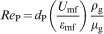
particle diameter, m
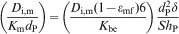
effective diffusivity in pellet, m2 s−1
diffusivity of ith gaseous species in multicomponent system, m2 s−1
shape factors for grain
shape factors pellet
feedrate, kg s−1
rate of product overflow from the bed, kg s−1
acceleration due to gravity, m s−2
superficial mole velocity of gaseous reactant through the packed bed, mol s−1
height above the distributor plate, m
dimensionless parameter (equation (32))
reaction rate constant

reaction rate constant at reference conditions (packed bed)
equilibrium constant
mass transfer coefficient of gas based on particle surface, m s−1
valuable of y* at the bed exit (equation (37))

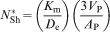
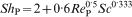
modified Sherwood number
pressure

reference pressure in the packed bed
particle Reynolds number at minimum fluidisation velocity
particle Reynolds number
Schmidt number
Sherwood number
time, s

average residence time in the fluidised bed

dimensionless time (equation (29))
temperature

reference temperature in the packed bed
bubble velocity, m s−1
minimum fluidisation velocity, m s−1
linear fluidisation velocity, m s−1
volume of grain, m3
volume of pellet, m3
bed weight, kg
fractional conversion of the pellet
total reduction of pellets with size d p in fluidised bed
local extent of solid in packed bed
overall extent of solid in packed bed
axial coordinate in packed bed, m
dimensionless axial coordinate (equation (28))
correction factor
effectiveness factor (equation (6))
effectiveness factor (equation (33))
bubble phase fraction in the bed
bed voidage at minimum fluidisation
bed void fraction in packed bed
initial porosity in particle
dimensionless gaseous reactant concentration (equation (27))
average viscosity of gas, N s m−2
average density of gas, kg m−3
average density of solid, kg m−3

generalised gas–solid reaction modulus
time for complete reduction of the pellet, s
Introduction
Two major types of chemical reactors used widely in non-catalytic gas–solid reactions are fluidised and packed bed reactors. A model for non-catalytic gas–solid reactions in packed beds was developed by Sampath et al.,1 in which they avoided using many of the simplifying assumptions of earlier models. Shettigar and Venkateswaran2 have studied non-catalytic reactions in a packed bed reactor using three transient models. Their system is applied to the simulation of regeneration of coked catalyst particles. Later, an unsteady state analysis of packed bed reactors for gas–solid reactions has been carried out by Park et al. 3 Simulation of iron ore reduction in a packed bed was performed by Aguilar et al. 4 In their work, different parameters such as bed characteristics and the flow of the reducing gas have been investigated. Cooper and Hallett5 have presented a numerical model for packed bed combustion of char particles. More recently, an improved one-dimensional model of a tubular packed bed reactor was presented by Koning et al.,6 in which the reaction rate has been calculated using the average temperature over the cross-section of the reactor.
On the other hand, Caram and Amundson7,8 presented a mathematical model for the gasification of char particles in a fluidised bed gasifier. In their work, the effects of different parameters, such as residence time distribution (RTD) and degree of mixing on carbon conversion, are investigated. The reduction of haematite particles to magnetite with hydrogen as a reducing agent in a small scale fluidised bed reactor was reported by Srinivasan and Sheasby.9 The haematite reduction takes place in three stages, and based on their results, the rate of reaction is controlled by the reaction kinetics at the gas/solid interface. Doherty et al. 10 have studied the reduction of haematite to wüstite by different mixtures of CO–CO2, H2–H2O and CO–CO2–H2–H2O in a small fluidised bed that was operated under bubbling conditions. Then, mathematical modelling of twin fluidised beds in which the reduction process of iron ore particles takes place in two stages was presented by Hahn and Chang.11 A good review of both experimental and computational studies of fluidised bed was presented by Halvorsen.12 Thurnhofer et al. 13 presented a mathematical modelling of the reduction of iron ore in a continuous lab scale fluidised bed reactor. In their work, the effect of RTD and kinetics on the reduction behaviour is investigated. Thereafter, a simplified model for non-catalytic gas–solid reactions in fluidised bed reactors was presented by Gomez-Barea et al. 14 Their model is defined based on catalytic gas–solid reaction models and can be used for different types of non-catalytic gas–solid reactions.
The non-catalytic gas–solid reactions in multiparticle systems, i.e. in reactors, are controlled by heat transfer usually because of being highly endothermic. On the other hand, in fluidised bed reactors, heat can transfer easily to the fluidised particles, and for this reason, selecting this type of reactor is recommended in highly endothermic or exothermic reactions. The pellets used in fluidised bed reactors are expected to be smaller in size than that used in packed bed reactors in order to ensure the ability to fluidise the solid and because using larger pellets will consume relatively more energy. Replacing a packed bed reactor with a fluidised bed can sometimes be very beneficial in industrial applications for specific reactions. Carrying the reaction in a fluidised bed reactor gives rise to many desirable features, such as omission of heat transfer resistance between gas and solid reactants, possibility of using powders and dust without a process of granulation and finally better conversion rates and amounts.
Comparison between these two reactors in the manner suggested above has not specifically been addressed in previous publications. In the present work, modelling of both fluidised bed and packed bed reactors is considered. The hydrodynamic behaviour of the fluidised bed has been described using the two-phase bubbling bed model and combined with the grain model for describing the reduction behaviour of solid oxide reactant in the fluidised bed. The modelling in the packed bed reactor is carried out based on previously reported work by Ranade and Evans.15 In a previous paper, we have described the application of the fluidised bed model with validation using experimental data.16 Finally, a comparison between the behaviours of the two types of reactors under varying conditions is made.
Mathematical modelling
Fluidised bed reactor
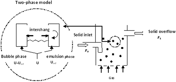
The two-phase bubbling bed model of Grace17 was used for modelling the fluidised bed, as shown schematically in Fig. 1. In this model, solid particles are well mixed, and two phases of emulsion and bubbles exist in the reactor. The solid particles are inside the emulsion phase and react with the gas phase that occupies most of the space inside the bubble phase. As the gas velocity increases from the minimum fluidisation velocity to higher values, the bubble fraction inside the bed will increase from a negligible to a significant amount.
Two-phase bubbling bed model
In the present work, bubbles are assumed to be spherical and increase in size because of coalescence while rising through the bed. Gas exchange between the emulsion and bubble phases takes place by bulk as well as by diffusion across the thin layer of cloud separating the two phases. The effect of external mass transport has been considered. In addition, the pellets are assumed to be spherical and consisting of spherical grains. As mentioned before, the fast circulation of solids and the high rates of heat transport result in an apparent isothermal behaviour of the reactor.
Governing equations
The minimum fluidisation velocity U
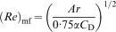
mf at which fluidisation is initiated is a significant parameter that can be calculated using the following equation18

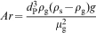
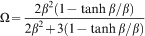
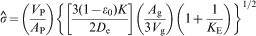
The Archimedes number and correction factor are calculated using the following relationships18

The drag coefficient proposed by Masliyah and Polikar20 for a porous sphere is given by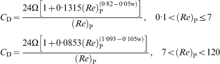


When a stream of bubbles rises through a bed, the velocity of an individual bubble is affected by the presence of the other bubbles. Under these circumstances, Davidson and Harrison22 suggested the following equation for the calculation of the bubble rise velocity U
b


The RTD of solids in the fluidised bed reactor is an important parameter to calculate the conversion inside the reactor, as will be mentioned in the end of this section. The RTD expression for a single stage, continuous reactor can be defined as23

The grain model was applied for the reduction of reactant particles with reducing gases. This model was introduced by Calvelo and Smith24 and Szekely and Evans25 and is based on the assumption that the grains in a pellet are surrounded by pores through which the gas must diffuse to arrive at a sharp interface between grain particles for the reaction to take place. As mentioned earlier, the grains are assumed to be spherical, and the effect of external mass transport has been considered. The general form of the reaction is expressed as


Packed bed reactor
Mathematical modelling of a packed bed reactor of porous pellets is based on Ranade and Evans’s modelling. The scheme of the packed bed is portrayed in Fig. 2. This figure denotes a packed bed arrangement where identical pellets that are assumed to be spherical consisting of spherical grains are charged into the column and the reactant gas is then passed through them. In Ranade and Evans’s mathematical modelling, a temperature gradient can also be considered along the axial position in the bed. The effect of external mass transport has been considered. As a result, a reaction front is formed, which gradually moves along the column axis.
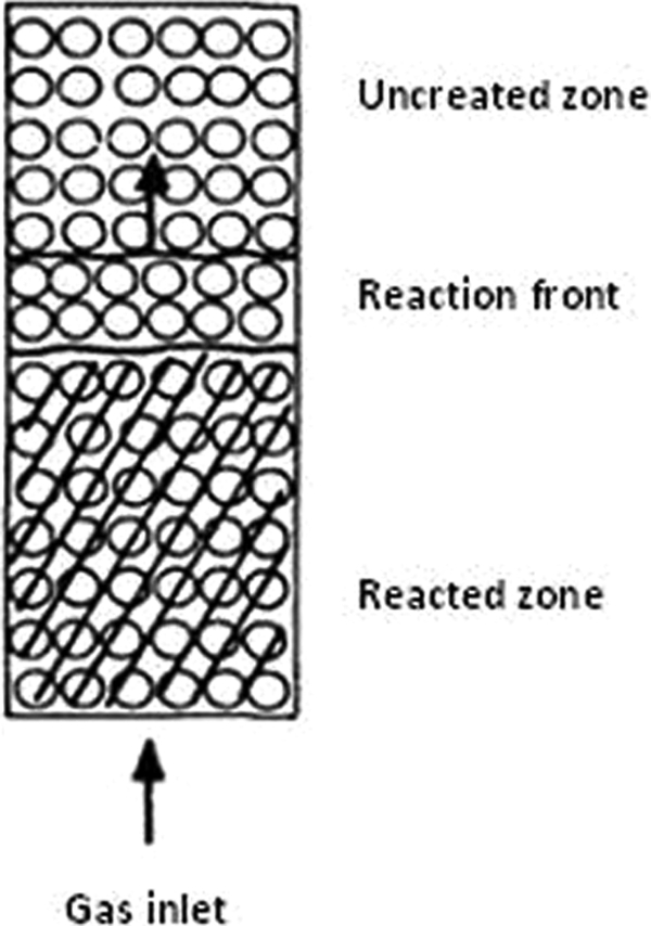
Schematic representation of packed bed reactor (Szekely and Evans)
Governing equations
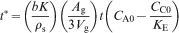
It is assumed that gas flows through the bed of a constant cross-sectional area containing pellets of uniform properties in the form of plug flow. Both dispersive and diffusive mass transports in the direction of gas flow are considered to be negligible and thus can be ignored. However, the mass transfer between the gas flow and the external surface of the pellet presents a resistance to the progress of reaction that cannot be ignored. Under these conditions, a material balance on the gaseous reactant yields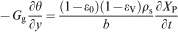


The dimensionless position and time are defined as


Using dimensionless parameters of equations (28) and (29), equation (26) can be written as follows


Solution algorithms and programming
Fluidised bed reactor
The system of equations presented for modelling the fluidised bed was numerically solved using the following scheme:
at a desired bed temperature, gas viscosity and density are calculated
the minimum fluidisation velocity is estimated using equations (1)–(8), and then the linear gas velocity is computed by considering a specified ratio of U 0/U mf(d P)
the average residence time is calculated from equation (12)
numerical values for bubble diameter, velocity and bubble fraction in the bed are determined from equations (9)–(11)
using equations (22)–(24), the particle Sherwood number, Reynolds number and interchange coefficient for mass transfer between bubble and dense phases are calculated, and the mass transfer coefficient and modified Sherwood number are estimated from equations (20) and (21) respectively
the time necessary for complete reduction in pellet is calculated from equation (18) and is used to calculate the average conversion in step (viii)
from the parameters calculated in step (v), the fractional conversion is estimated using equation (18)
using RTD, the time calculated in step (vi) and the fractional conversion calculated from the previous step, the average conversion is computed from equation (25).
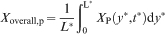
Figure 3 shows the algorithm for solving the governing equations. The calculations have been carried out in two main sections in the hydrodynamic and grain model. The appropriate equation numbers are brought in from respective boxes. Input data are shown in circles and ovals, and calculations are depicted in rectangles. The calculated parameters are exhibited on each output arrow.
Algorithm of solution of equations in fluidised bed
A program was developed in MATLAB software that is able to solve hydrodynamic and grain model equations, with considerations for both changes in the pellet size and hydrodynamic properties of fluidised bed at different temperatures and pressures. In order to reduce the computation time, the matrix operation facilities in MATLAB have been used. These operations can minimise the number of loops applied in the program. The equations were solved numerically using the Newton–Raphson method.
Packed bed reactor
The system of equations presented for modelling the packed bed reactor can be numerically solved using the following scheme:
temperature 


the length of reactor in the axial coordinate is divided into grids, and the temperature and total pressure in each axial position of the reactor are calculated
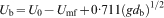
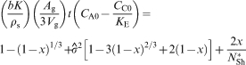
dimensionless parameters such as y*, k s and β p for different axial positions in the reactor are calculated from equations (28), (32) and (33)
the dimensionless time 
the numerical solution of equation (36) yields the local extent of reaction in the bed
the computed overall extent of reaction in the packed bed is calculated from equation (37).
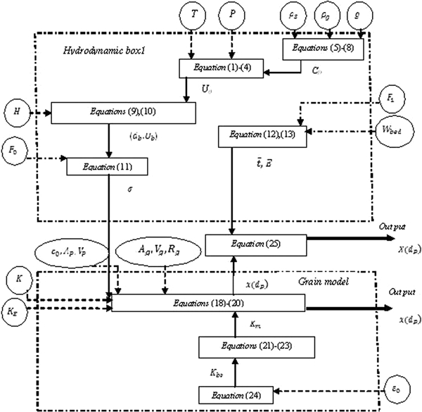
Figure 4 shows the algorithm of the solving equations.
Algorithm of solution of equations in packed bed
As in the fluidised bed reactor, in this case also, the program was developed in MATLAB software for solving the governing equations. The Runge–Kutta technique coupled with Simpson’s rule is used to solve the equations.
Model validation
Fluidised bed reactor model
The data obtained by Srinivasan and Staffansson28 (referred as SS90) were used for fluidised bed model validation. In SS90, the shrinking unreacted core model has been used for the description of the hydrogen–iron ore reaction, and iron oxide pellets of the specified characteristics (composition and porosity) are fluidised under isothermal conditions by a stream of hydrogen at 1073 K and 1·5 atm. The data used as input are presented in Table 1. The comparison between the present work results and the SS90 data is shown in Fig. 5.
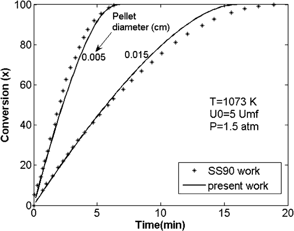
Comparison between present work results and SS90 data under fluidised bed condition
Parameters used as inputs for modelling of reduction of iron ore in fluidised bed reactor
As it is seen, there is a good agreement between the results, and the model proposed can be used to predict the behaviour of the reactor. A detailed description of the present mathematical model was reported by Maroufi et al.
Packed bed reactor model
The experimental data obtained by Ranade and Evans were used for the validation of the packed bed model. In addition, the same modelling presented by them was used to predict the reactor behaviour. Table 2 shows the experimental data used as inputs of the program written in this case.
Parameters used as inputs for modelling of reduction of iron ore in packed bed
The comparison between the present work results and the experimental data in the same condition of the beds is depicted in Fig. 6.
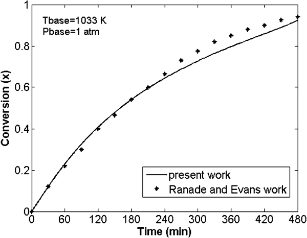
Comparison between present work results and Ranade and Evans data under packed bed condition
In this case also, an acceptable agreement is seen between model prediction and experimental data, and the model can be used in the following studies.
Results and discussion
The reduction of iron oxide with hydrogen is considered in the mathematical modelling of two types of reactors, and the comparison between different behaviours of reactors is discussed in the present section. The hydrodynamic parameters of the bed (height of bed, diameter and bed weight), the size of the grains and the content of reducing gas in the inlet gas mixture are assumed to be identical in modelling the two types of reactors.
There are some significant points in the fluidised bed reactor that should be noted here. The fast circulation of solids within the bed, coupled with the high rates of heat transfer, results in an apparent isothermal behaviour of the reactor. Therefore, in this work, reactant pellets of specified characteristics (composition, porosity) are fluidised under isothermal conditions by a stream of reducing gas. As well as in order to achieve fluidisation phenomenon in a fluidised bed reactor, pellets need to be far smaller than those in a packed bed. The input data used in the program of the fluidised bed reactor are given in Table 3.
Parameters used as inputs for modelling of reduction of iron ore in fluidised bed reactor
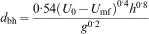
In the second step, the reduction of iron oxide pellets in a packed bed reactor is modelled based on Ranade and Evans’s modelling. Based on their work, a temperature variation of up to 180 K is considered through the bed. In this case, a stationary packed bed of porous pellets is filled inside the reactor, and a hydrogen stream passes through the bed. The temperature is assumed to be uniform within the pellet in axial positions inside the reactor. The reference temperature of 973 K is chosen as the temperature at the inlet of the bed where the gaseous reactant is flowing into the reactor. The necessary input data used in the mathematical modelling of the packed bed are the same those mentioned for fluidised bed except for the pellet size, which is chosen as 1·1 cm.
As can be seen, there is a significant difference between sizes of iron oxide pellets used in fluidised and packed bed reactors. In packed bed reactors, the pellets are stationary and do not matter if they are large, while in a fluidised bed reactor, the size of pellets is an important parameter in modelling for fluidisation to be achieved.
The effects of different parameters, such as temperature, structural geometries of the solid reactant and content of reducing gas in the inlet gas mixture, are investigated on both fluidised and packed beds and discussed in the following sections.
Temperature
Temperature is an important parameter whose effect must be evaluated in gas–solid reactors. As mentioned before, in the present work, reactant pellets are fluidised under isothermal conditions by a stream of pure hydrogen. The effect of temperature on the rate of reduction under fluidised bed conditions for pellets of 0·06 mm diameter is depicted in Fig. 7. However, in the packed bed reactor, there is a temperature gradient along the bed, and the temperatures at the inlet, middle and outlet of the reactor are 973, 883 and 793 K respectively. The conversions in the fluidised bed under these three temperatures are shown in Fig. 7. As expected, the rate of conversion in a fluidised bed reactor increases with increasing temperature. However, the difference is not that impressive.
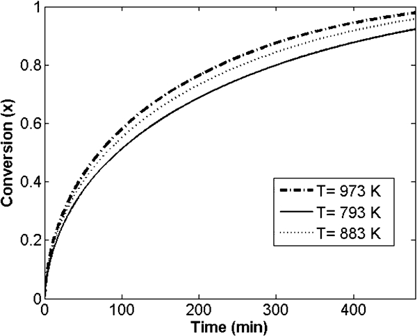
Effect of temperature on conversion under fluidised bed conditions (d P = 0·06 mm, pure H2)
The results of the modelling of the packed bed for three selected reference temperatures are shown in Fig. 8. An increasing temperature in the packed bed leads to an increase in the conversion of reactants. As can be seen, the difference between the rates of reduction for these three conditions is considerable. This shows that the effect of temperature on the performance of the packed bed is more significant than that in the fluidised bed. The temperature gradients along the bed for these three temperatures are depicted in Fig. 9 for 1·1 cm pellet sizes under pure hydrogen stream.
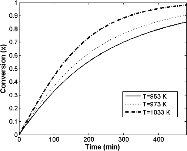
Effect of temperature on conversion under packed bed conditions (d P = 1·1 cm, pure H2)
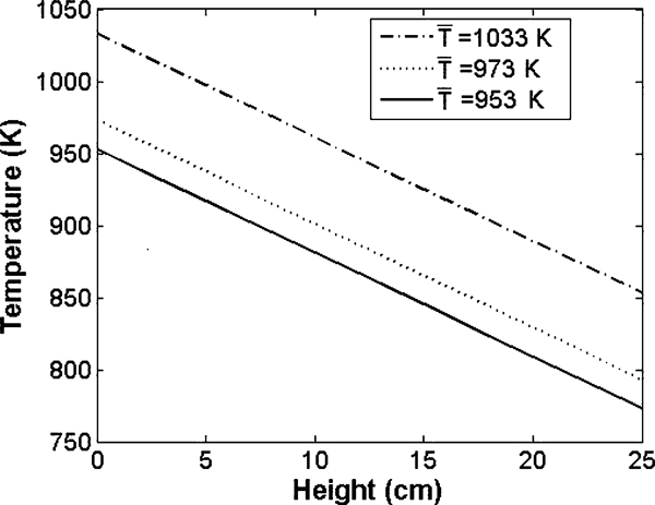
Temperature gradient along packed bed
A comparison between the performances of the fluidised bed and the packed bed reactor, under the same condition of temperature, is shown in Fig. 10. It should be noticed that 973 K is the temperature at reference condition of the packed bed, while this value is constant along the fluidised bed. By noting that smaller granules are used in a fluidised bed than in a packed bed, a fluidised bed shows a better degree of conversion than a packed bed. Achieving a value of 0·99 in the former in comparison with a value of only 0·90 in the latter after a duration of 480 min is observed. This difference in performance arises from the fact that there is a temperature gradient along the packed bed while it is absent in a fluidised bed.
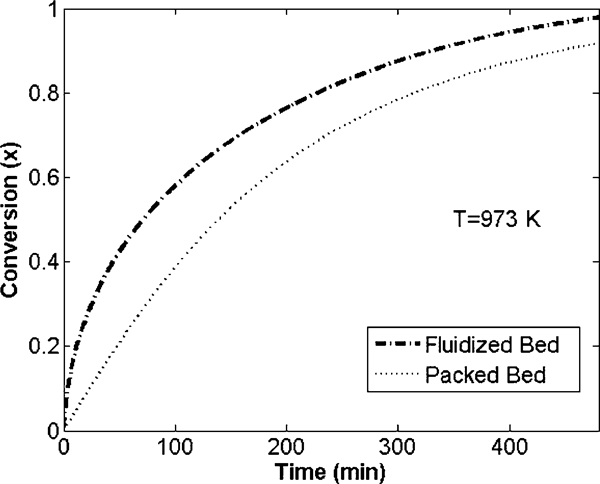
Comparison between fluidised and packed bed reactors at same temperature (d P, packed = 1·1 cm, d P, FB = 0·06 mm, pure H2)
Pellet size
The size of the pellet is expected to have a major effect on the rate of conversion. This effect on the reduction rate of iron oxide particles under fluidised bed conditions for the temperature of 973 K under pure hydrogen stream is shown in Fig. 11. At a given time, the extent of reaction can be noted to decrease with increasing pellet size. The sharp increase in the conversion with the decrease in the pellet size is noticeable. After 480 min of reaction time, a conversion of only 0·73 is achieved using pellets of size 0·1 mm, which is increased to 0·99 with 0·06 mm pellets. The smaller particles can be fluidised more effectively, and the resulting faster circulation of solids within the bed can improve the mass transport.
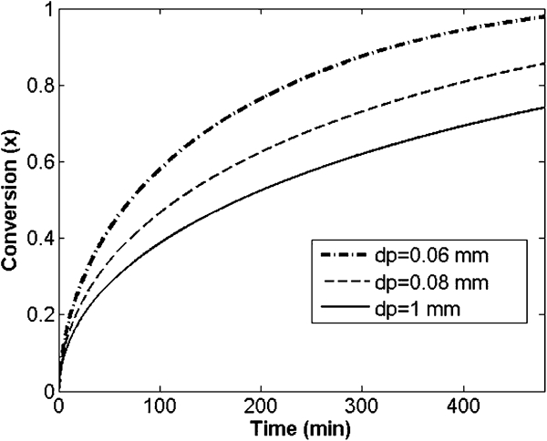
Effect of pellet size on conversion under fluidised bed conditions (T = 973 K, pure H2)
The effect of pellet size on the rate of reduction of the iron oxide under the packed bed condition is depicted in Fig. 12 for the same temperature of 973 K and under pure stream of hydrogen. As can be expected, the extent of reaction in the pellets decreases with the increase in pellet size. However, the difference in reduction rate is not as noticeable as that in the fluidised bed. In addition, in the packed bed, the pellets are stationary and not required to be small as they need to be in the fluidised bed. In packed bed, very small particles must be avoided in order to minimise loss by carry over and to avoid loss of permeability, channelling or choking of the bed.
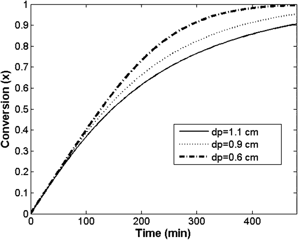
Effect of pellet size on conversion under packed bed conditions (T = 973 K, pure H2)
A comparison between two reactor behaviours (shown in Figs. 11 and 12) shows that if we discard the effect of pellet sizes, fluidised bed reactors show a better trend in conversion curves.
Reducing gas composition
The content of hydrogen in the inlet gas is another important parameter varied in this section while keeping the temperature and pellet size constant at 973 K and 0·06 mm respectively. The effect of changing the effective average gas composition in the bubble phase on the performance of the fluidised bed is shown in Fig. 13. Increasing the reducing agent in the feed gas mixture from 0·8 to 1·0 leads to a considerable increase in the average conversion of the reaction.
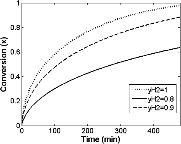
Effect of reducing gas composition on conversion under fluidised bed condition (T = 973 K, d P = 0·06 mm)
The effect of reducing gas composition on the rate of reduction under the packed bed condition has been considered as well for a fixed temperature of 973 K and pellet size of 1·1 cm. The results are seen in Fig. 14. As shown, the average conversion increases with the content of hydrogen in the feed gas. However, the difference between the conversions of reaction in the various reducing gas compositions in the fluidised bed reactor is more than that in the packed bed. With a small decrease in the reducing gas composition, the rate of reduction in the fluidised bed sharply decreases. This shows that the content of reducing gas in the feed gas has a more pronounced effect on the performance of the fluidised bed.
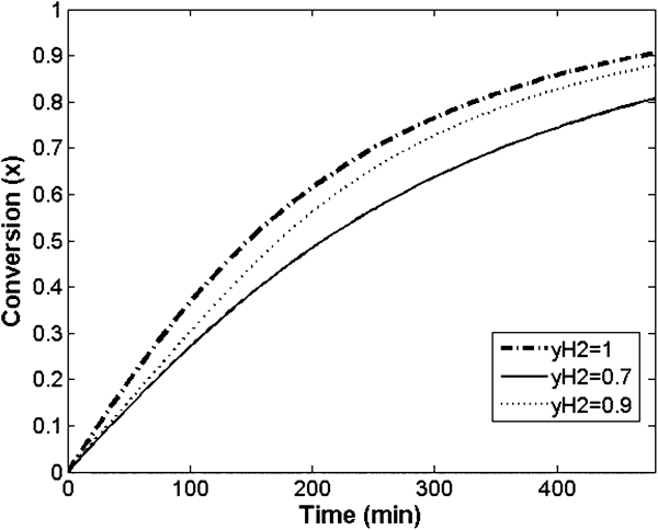
Effect of reducing gas composition on conversion under packed bed condition (T = 973 K, d P = 1·1 cm)
The behaviours of the fluidised bed and the packed bed reactor have been compared at the same condition of inlet gas composition and temperature (
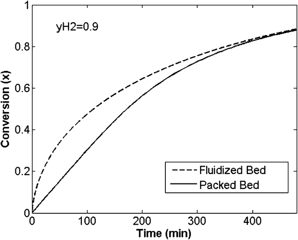
Comparison between fluidised and packed bed reactors at same condition of inlet gas (d P, packed = 1·1 cm, d P, FB = 0·06 mm and T = 973 K)
Conclusions
Mathematical modelling of fluidised and packed bed reactors was carried out, and a comparison of the conversion of non-catalytic gas–solid reactions has been reported for varying parameters. Fluidisation of solid particles in fluidised bed reactors results in lowering the heat transfer resistance outside the particles and is beneficial to highly endothermic or exothermic reactions. In packed bed reactors, there is always heat transfer resistance that affects the rate of reaction of solid particles followed by decreasing in solid reactant conversion. The two-phase bubbling bed model and a steady one-dimensional model were used in the mathematical modelling of fluidised and packed bed reactors respectively, and numerical algorithm was applied to solve the governing equations.
The comparison between two types of reactors confirms that at different temperatures, the conversion achieved by solid reacting in fluidised bed reactors is higher than carrying out the reaction in packed bed reactors without considering the additional effect of pellet size used in each reactor. Indeed, the differences between conversion curves resulting at different temperatures in fluidised bed reactors are smaller than those similar curves in packed bed reactors. Therefore, the effect of variation in temperature inside the packed bed reactors is an important issue, and by carrying out the same reaction in a fluidised bed reactor, this problem can be resolved as temperature variation is greatly minimised.