
Abstract
Physical model experiments have been conducted to investigate the effects of multihole orifices in the upleg snorkel on bubble behaviour and decarburisation rate during Ruhrstahl–Heraeus refining. Bubble behaviour was recorded by a high speed video camera and a volumetric mass transfer coefficient kA/V was used to evaluate the decarburisation rate. Measurement of the volumetric mass transfer coefficient kA/V was made by means of the CO2 desorption from a NaOH solution. Pictures of bubble behaviour show that gas bubbles are generated separately from the multihole orifice in the low region of gas flowrate, but they tend to coalesce at high gas flowrate. It was demonstrated that kA/V increases with increasing gas flowrate and decreasing orifice hole diameter. In the low region of gas flowrate, kA/V for multihole orifices is larger than that for one-hole orifices. In this case, kA/V increases as the number of holes increases, and the hole distance of orifice has little effect on kA/V. However, in the high region of gas flowrate, kA/V for multihole orifices is lower than that for one-hole orifices, and kA/V decreases with the increase in orifice interhole distance. It was found that there exists a critical gas flowrate, above which kA/V for multihole orifices is lower than that for one-hole orifices. This critical value increases with increasing hole distance and hole number. Some explanations were also made in terms of bubble behaviour.
Introduction
In recent years, the Ruhrstahl–Heraeus (RH) degasser has been widely applied for the production of ultralow carbon steels, such as interstitial free and non-oriented electrical steels. Bubble behaviours, such as bubble size and bubble frequency, are key factors to the decarburisation efficiency,1, 2 and some researches have already been conducted to elucidate bubble behaviour during RH refining.3 – 6
Kamata et al. 3 investigated the effects of orifice diameter, orifice number, injection depth and gas flowrate on the circulation flow characteristics in RH using a water model. It was found that the circulation characteristics of the reactor were greatly affected by the diameter and the number of orifices and they attributed these results to the changes in bubble size and the bubble frequency in the upleg snorkel. da Silva et al. 4 examined the influence of nozzle blockage on the circulation rate through a physical model study. It was shown that a non-symmetrical nozzle blockage led to a large drop in the circulation rate. Seshadri et al. 5 found that bottom gas injection practice under the upleg improved the circulation rate, and increasing the circulation rate by bottom injection could increase the degassing rate. Neves et al. 6 evaluated the effect of gas injection in the vacuum chamber on the melt circulation and decarburisation rates using a physical model. It was observed that the injection of gas in the vacuum chamber could increase the decarburisation rate under certain conditions. However, in these researches, only one-hole nozzles or one-hole orifices were adopted in the upleg snorkel to introduce gases into the liquid. Little information is known about the effect of multihole orifices on bubble behaviour, which may further decrease bubble size and enhance the refining efficiency of decarburisation during RH refining.
In the present work, physical model experiments were conducted to make clear the effects of multihole orifices in the upleg snorkel on bubble behaviour and decarburisation rate during RH refining.
Experimental apparatus and procedure
A schematic diagram of the experimental set-up of the RH model is shown in Fig. 1. Table 1 presents the main parameters of the physical model. The vacuum chamber was connected to two snorkels which were immersed into the water bath of the ladle. The immersion depth was 110 mm. The liquid depth in the vacuum chamber was maintained at 74 mm using a vacuum pump and a manometer. N2 or CO2 was introduced into the bath through a layer of nine even distributed orifices in the upleg snorkel. The gas flowrate Q was controlled by using a rotameter in a range of 5–50 NL min−1.
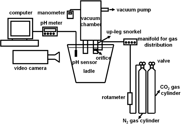
Schematic diagram of experimental set-up of RH model
Parameters of physical model
Configurations of orifices are shown in Fig. 2, dimensions of which are listed in Table 2. The hole number N, the diameter of holes d i, the distance between holes d h and the outer diameter of orifices d o are also shown in Fig. 2.
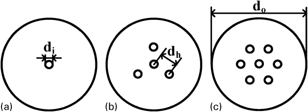
Configurations of orifices for gas injection
Dimensions of orifices for gas injection
Bubble behaviour for the orifices in the upleg snorkel was recorded by a high speed video camera with a shutter speed of 1/2000 s.
A volumetric mass transfer coefficient kA/V, which is the product of relative interfacial area A/V and mass transfer coefficient k, is generally used to evaluate the decarburisation rate.5,
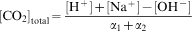
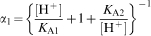
6 CO2 desorption from a NaOH solution was used to measure the volumetric mass transfer coefficient kA/V. CO2 was first dissolved into a 0·02 mol L−1 NaOH solution until pH<6. Then, the operation of the RH model was started, and N2 was injected into the solution through the orifices to cause the desorption of CO2. The variation in pH value was measured continuously using a pH sensor. No significant difference in the experiment results was found when different locations for the pH sensor were tried. The decrease in the total CO2 content is exclusively caused by the decrease in dissolved CO2 for pH value from 6 to 8. From the relationship between CO2 concentration in the NaOH solution and the N2 injection time, the volumetric mass transfer coefficient kA/V can be obtained. The total CO2 content was calculated from the pH value by equations (1)–(6)7

Results
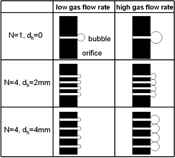
The pictures in Fig. 3 are photographs of bubbles immediately after they broke away from the orifices. The bubbles released from four-hole orifice are smaller than those released from one-hole orifice at a low gas flowrate of 8·3 NL min−1, as shown in Fig. 3a and b . However, at a high gas flowrate of 41·7 NL min−1, the bubbles generated from four-hole orifice seem larger than those generated from one-hole orifice, as illustrated in Fig. 3c and d . This means that, although gas bubbles are formed separately from the multihole orifice at low gas flowrate, they tend to coalesce above a certain gas flowrate.
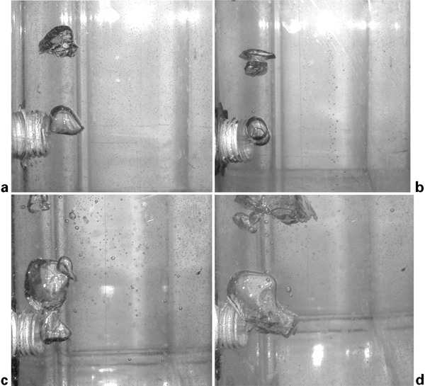
Bubbles immediately after they broke away from orifices in upleg snorkel
Figure 4 shows a typical relationship between CO2 concentration in the NaOH solution and the N2 injection time.
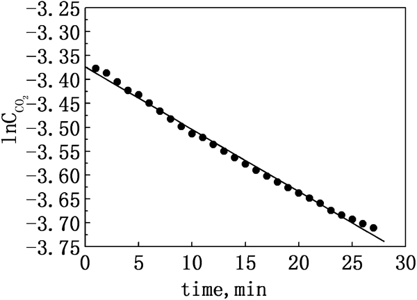
Typical relationship between CO2 concentration in NaOH solution and N2 injection time
Therefore, CO2 desorption reaction can be represented by equation (7), which is regarded as a first order reaction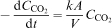

The variations in kA/V as a function of gas flowrate for orifices with different hole diameters, hole distances and hole numbers are shown in Figs. 5 7, in which one-hole orifice with the hole diameter of 1 mm was chosen as d h = 0 and N = 1 for comparison in Figs. 6 and 7 respectively.
Variation in kA/V as function of gas flowrate for one-hole orifices with different hole diameters
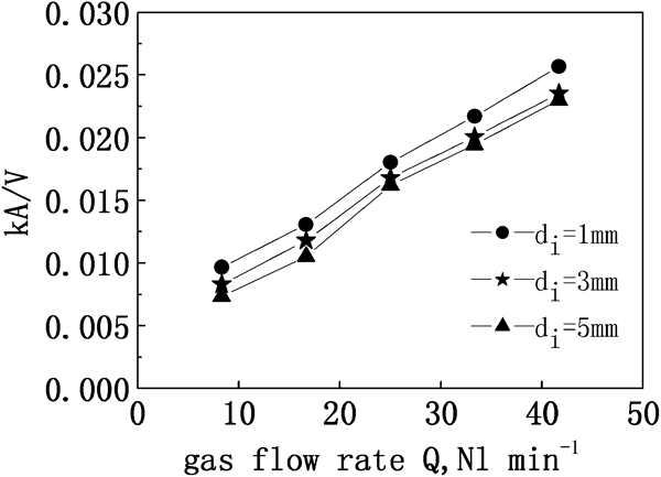
Variation in kA/V as function of gas flowrate for four-hole orifices with different hole distances
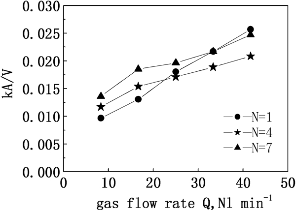
Variation in kA/V as function of gas flowrate for orifices with different hole numbers
As seen from these three figures, kA/V increases with increasing gas flowrate and decreasing orifice hole diameter. In the low region of gas flowrate, kA/V for multihole orifices is larger than that for one-hole orifices. In this case, kA/V increases with the increase in orifice hole number and the orifice hole distance has little effect on kA/V. However, in the high region of gas flowrate, kA/V for multihole orifices is lower than that for one-hole orifices, and kA/V decreases with the increase in orifice hole distance.
Discussion
Sano et al. derived equation (8) to describe the size of bubbles generated at one-hole orifices8
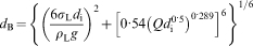
As seen from equation (8), bubble size decreases with decreasing hole diameter when the gas flowrate is kept constant, which leads to a larger gas/liquid interfacial area, hence a larger value of kA/V, as shown in Fig. 5. Although larger bubbles are generated at higher gas flowrate, the gas/liquid interfacial area will become larger because the bubble frequency also increases with increasing gas flowrate. Therefore, kA/V increases with the increase in gas flowrate, as shown in Fig. 5.
For multihole orifices, equation (8) can be modified into equation (9)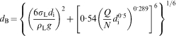
Formation mechanism of fine and large bubbles at low and high gas flowrates respectively
It seems that the hole distance has little effect on kA/V at low gas flowrate. However, at high gas flowrate, kA/V decreases with the increase in orifice hole distance, as shown in Fig. 6. This is probably because at low gas flowrate, fine bubbles are generated from each hole, as indicated in equation (9). In this case, the hole distance is sufficient for avoidance of bubble coalescence, and thus small bubbles are formed individually irrespective of the hole distance. Nevertheless, at higher gas flowrate, bubbles generated from each hole become larger, so the hole distance is too short to avoid coalescence of these large bubbles, as shown in Fig. 3d , resulting in a smaller value of kA/V. Obviously, it is difficult for bubble coalescence to happen at a longer hole distance, but once it does occur, bubbles become much larger. The formation mechanism of large bubbles due to coalescence at high gas flowrate is schematically illustrated in Fig. 8.
It was found that there exists a critical gas flowrate, above which kA/V for multihole orifices is lower than that for one-hole orifices. This critical value increases with increasing hole distance and hole number, as shown in Figs. 6 and 7. Therefore, for a given gas flowrate, the hole distance and hole number must be optimised for multihole orifices in order to gain a larger critical gas flowrate and hence enhance the decarburisation efficiency. For instance, in order to increase the decarburisation rate at higher gas flowrate, the hole distance and the hole number must be increased.
Table 3 lists the relative gain for kA/V when multihole orifices are adopted. It is shown that the largest relative gains for four-hole and seven-hole orifices are 20·99 and 41·66% respectively. Thus, if the multihole orifices with optimised hole distance and hole number are applied for RH degasser, much higher decarburisation efficiency would be achieved even without any increase in gas flowrate.
Relative gain for kA/V of multihole orifices
Conclusions
Physical model experiments have been performed to clarify the effects of multihole orifices in the upleg snorkel on bubble behaviour and decarburisation rate during RH refining. The main findings are as follows.
The bubbles released from multihole orifice are smaller than those released from a one-hole orifice at low gas flowrate. However, at high gas flowrate, the bubbles generated from multihole orifice are larger than those generated from a one-hole orifice. This is probably because individual gas bubbles are generated from the multihole orifice in the low region of gas flowrate, but they tend to coalesce at high gas flowrate when the hole distance is insufficient to avoid bubble coalescence.
kA/V increases with increasing gas flowrate and decreasing orifice hole diameter. In the low region of gas flowrate, kA/V for multihole orifices is larger than that for one-hole orifices. In this case, kA/V increases with the increase in orifice hole number and the hole distance of orifice has little effect on kA/V. However, in the high region of gas flowrate, kA/V for multihole orifices is lower than that for one-hole orifices, and kA/V decreases with the increase in orifice hole distance.
There exists a critical gas flowrate, above which kA/V for multihole orifices is lower than that for one-hole orifices. It is found that this critical value increases with increasing hole distance and hole number. For a given gas flowrate, the hole distance and hole number must be optimised for multihole orifices in order to gain a larger critical gas flowrate and hence enhance the decarburisation efficiency. It is shown that the largest relative gains for four-hole and seven-hole orifices are ∼20 and 40% respectively.
Footnotes
Acknowledgements
The financial support of the State Eleventh Five-year Plan (no. 2006BAF03A13) is gratefully acknowledged.