
Abstract
In order to improve the flatness of hot rolled thin gauge steel strip, a new type of roll contour configuration was developed for a four-high temper rolling mill based on the finite element method analysis. The roll contour configuration consists of a variable contact back-up roll contour and a positive crown work roll contour. Both can be described as sixth order polynomial functions. The variable contact back-up roll not only reduces the roll stack deflection and contact stress concentration between work and back-up rolls, but also increases the control capability of the bending force of the work roll. Positive crown work roll contour is utilised to compensate roll wear and in turn the length of temper rolling schedule can be prolonged. After this roll contour configuration was applied on the temper rolling mill of Qiangang Company of Shougang Group, the flatness of hot rolled thin gauge strip was improved by 10% and the working efficiency was also increased as the length of temper rolling schedule was increased.
Introduction
Flat rolled steel products are important and widely used in modern society. With the intensive competition in steel manufacturing markets, there are two ways for hot strip manufacturers to increase their competitiveness. One is to develop new products that are low cost and of high economic and social effectiveness; the other is to improve the quality of the products. Thin gauge strip production through hot rolling has enormous economic benefits:1 partly substituting cold rolled strip and in turn reducing the investment on cold rolling mills; reducing the rolling passes even though further cold rolling is needed. Up until now, the thinnest steel strip after hot rolling can be below 1·2 mm. For realising the stable rolling of the thin gauge strip with sound flatness quality, not only have new types of rolling mills such as mini, endless or semiendless hot strip production lines been developed, but also new techniques such as ferritic rolling and flying gauge control have been employed.2 – 7 Currently, in China, thin gauge strips (thickness <2·0 mm) are produced by compact strip production lines and conventional hot rolling mills. Temper rolling will be employed to improve the flatness quality of hot rolled thin gauge strip before it is delivered to the customer.
Temper rolling or skin pass rolling is a cold rolling process in which the sheet metal is subjected to a slight reduction (0·5–4%) in thickness. The purpose of the temper rolling process is to provide a degree of surface hardening, restore temper, prevent stretcher strains (Lueder’s bands), and impart a desired finish and a desired degree of flatness.8 Many analytical and experimental work on the deformation models of roll and strip,9 – 13 roughness transferring14 – 17 and material properties18 in temper rolling or skin pass rolling processes have been carried out. However, only limited research on the shape control of the temper rolling process can be found. A kind of back-up roll contour was applied on temper rolling mills to improve the flatness control capability as described in Ref. 19. A shape decision and control system was developed by Hur and Choi20 and implemented on the skin pass mill by means of fuzzy logic.
Similar to hot rolling mills, there are many factors influencing the flatness improvement effect in temper rolling mills such as roll crown, roll force, bending force, operator’s experience and so on. Roll contour technology is well known as a direct and effective measure to increase the flatness control capability of the rolling mill. As a result, many roll contours and rolls with special structures are able to change the roll crown, such as the dynamic shape roll,21 Nipco rolls,22 and variable crown rolls. 23 23,24 However, these rolls have complex mechanical and hydrosystem structures, and are not widely used. On the contrary, roll contours are adopted in many rolling mills because they are easily achieved by grinding the contour curves on roll surfaces without any complex structure changes.25 Therefore, roll contour technology also can be utilised in temper rolling or skin pass mill to improve strip flatness quality.
In this work, a roll contour configuration consisting of the variable contact back-up roll contour and the positive crown work roll contour was designed and applied on the temper rolling mill for thin gauge strip processing instead of the conventional cylinder rolls. As a result, the flatness quality was improved by a large factor during the temper rolling of hot rolled thin gauge strip.
Roll contour design and roll contour configuration
Introduction of thin gauge strip production
The 1580 mm hot strip mill of Qian’an Iron and Steel Co., Ltd of Shougang Group was commissioned at the end of 2009. This mill consists of four walking beam reheating furnaces, a high pressure water roughing descaler, a slab size presser, one two-high reversible roughing mill (R1), one four-high reversible roughing mill (R2) with an edge rolling mill at its entrance (E2), a heat insulating cover, an edge heater, a crop shear, a high pressure water finishing descaler, seven stands of four-high finishing mills with an edge rolling mill at entrance, run-out table cooling, two downcoilers. Continuously variable crown work roll contour, bending force of utmost 1500 kN and work roll shifting with a stroke of 150 mm are employed as three major measures for controlling strip shape. IMS profile and Rometer F200 flatness gauge meters were installed at the exit of the finishing train to measure and record the strip profile and flatness.
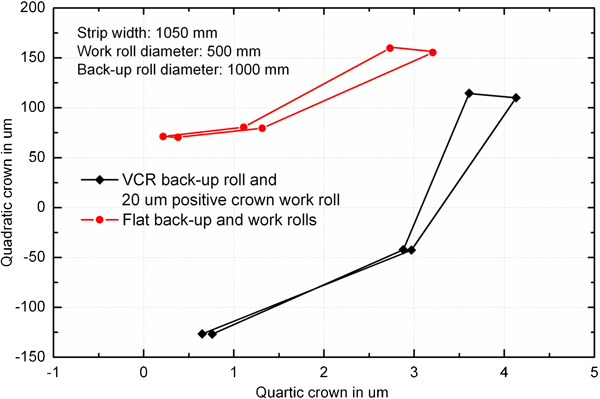
Thin gauge steel strip for ship container grade SPA-H with 1·6 mm thickness and 1170 mm width are produced by this mill. As is well known, the thinner the strip, the more difficult it is to control the strip flatness during hot rolling, especially for head and tail ends. Also heavy edge waves, as seen from the flatness measurements shown in Fig. 1 and the coil shape photo shown in Fig. 2, are produced. Before the thin gauge strips are delivered to the customer, they are temper rolled to ensure the flatness quality and head and tail ends with heavy wavy defects are cut off. Even though these thin gauge strip coils were already temper rolled, there were still many flatness quality complaints from customers due to non-flat strip defects showing up during the uncoiling of the thin gauge strip.
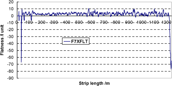
One example of coils’ flatness results detected by meter after hot rolling
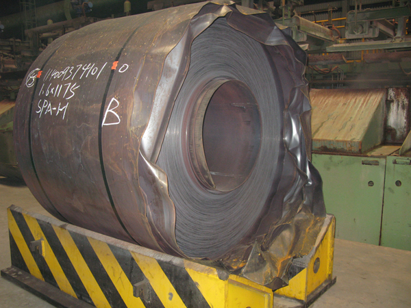
Example photo of coil shape of thin gauge strip
The reason for the flatness problems still existing after temper rolling is that the temper rolling mill has no capability to correct the heavy waves and thus it is necessary to increase the shape control capability of the temper rolling mill for the thin gauge strip to improve flatness quality before effective measures can be found out to obtain the thin gauge strip with a sound flatness quality through hot rolling.
The four-high hot temper rolling mill of Qian’an Iron and Steel Company of Shougang Group used to process thin gauge strips was designed and produced by Mino Company of Italy. The barrel lengths and the diameter ranges of work and back-up rolls are 2700 and 2200, 500–550 and 1000–1100 mm respectively. The width and thickness ranges of strip that can be temper rolled are 900–2100 and 1·2–6·5 mm respectively. The maximum rolling force, the bending force and shifting stroke of the work rolls are 1500 t, 30 t/chock and 200 mm respectively. Front and back tensions can reach up to 30 and 18 t respectively. The layout of the temper rolling mill is shown in Fig. 3.
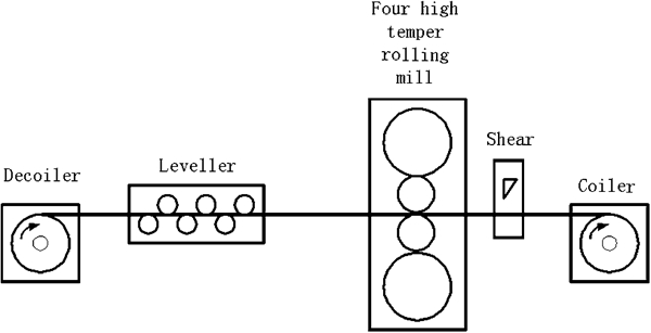
Layout of temper rolling mill
Although temper rolling has a small reduction of <4%, roll deflection, wear and flattening also exist and have detrimental effects on flatness improvement. There is no flatness measurement device and shape control set-up model in this mill; therefore, the flatness can only be judged according to the operator’s observation and experience during rolling. In addition, high tension is built into strip during temper rolling, and it is difficult for the operator to make a correct judgment on the real flatness quality. Another major issue is that the temper rolling mill has no strong capability for correcting the non-flat strip because there is no contour ground on both work and back-up rolls. As a result, some thin gauge strips with flatness defects uncorrected in temper rolling are also delivered to users. It is not surprising for so many complaints about the flatness quality of thin gauge strip to take place as mentioned before. Similar to hot rolling mill stand, roll contour and configuration techniques also can be employed on temper rolling mills to increase the shape control capability.
Roll contour design
Roll contour design and optimisation were carried out on the temper rolling mill to improve the shape control ability based upon the work experience26 on hot rolling mills.
One kind of variable contact back-up roll (VCR) contour curve with a sixth order of polynomial was designed and is shown in Fig. 4. The core idea of the VCR contour is that the contact length between work and back-up rolls can be varied with the width of strip rolled and the rolling force. Three main width gauges, namely 1000, 1200 and 1500 mm, to be rolled were considered when the VCR was designed. The contour curve is symmetrical with the roll barrel centre, and each half part of the curve actually composed of three sections. First, roll stack deflection analysis was carried out by the finite element method (FEM)27 in which three specific strip width gauges and no roll contour were considered. The crown of each section was determined according the FEM analysis results. Then the VCR curve is designed by fitting the three crown data to be a sixth order polynomial on which smooth transits are made through the three crowns. Because different strip widths are considered, the VCR contour curve can make the contact length between work and back-up rolls adapt with the strip width. In turn it can realise the functions of keeping uniform contact pressure between rolls. Variable contact back-up roll can also raise the cross rigidity of the loaded roll gap and then increase the shape control capability of the temper rolling mill.
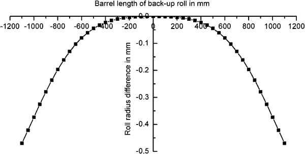
Variable contact back-up roll contour curves for temper rolling mill
The function of VCR back-up roll contour curve can be expressed as follows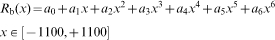
During the temper rolling process, the work roll will wear unevenly along its barrel length. Heavier wear locates at the place where roll contacts with the strip edge than the central position. As a result it is difficult to control flatness even though the maximum bending force is used during the mid or late period of the temper rolling schedule. To compensate for the roll wear, positive crown work roll can be employed. Because the wear on the roll edge is heavier than that on the central part, it is not suitable for using parabolic curves as positive crown contours. In order to compensate for the wear of the work roll and increase the shape adjustment ability of the temper rolling mill, a positive crown work roll contour with a sixth order of polynomial was designed, and its comparison with a parabola is also shown in Fig. 5

Positive crown contour curves for work roll of temper rolling mill
Performance analysis of roll contour configuration
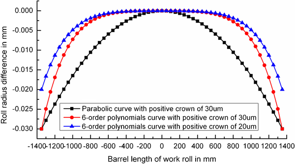
After finishing the design work of the VCR contour and the positive crown contour, a performance analysis of the roll shape configuration was carried out. In this work, roll stack deflection calculations were all carried out using the two-dimensional thickness variable FEM,27 as shown in Fig. 6, which has features of a high precision and a rapid calculation speed.
Two-dimensional thickness variable FEM model for four-high rolling mill
In the analysis work, two roll contour configurations, i.e. cylinder work and back-up rolls, VCR contour and positive crown work roll, were taken into account and comparisons were made on shape control characteristics including the loaded roll gap, the profile adjustment area of loaded roll gap and contacted pressure distribution between work and back-up rolls. From the comparison results, the configuration of the VCR and positive crown work roll can realise the functions of keeping uniform contact pressure between the rolls, raising the cross rigidity of the loaded roll gap and a larger crown adjustment area on the temper rolling mill. In turn, this roll contour configuration increases the shape control capability of the temper rolling mill.
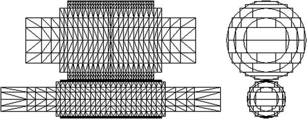
Figure 7 is one example of the loaded roll gap profile comparison between two kinds of roll contour configurations under the same working conditions. It can be seen that the contour configuration of the VCR and 20 μm positive crown work roll has an effect of a reduction of 50 μm on roll stack deflection under the working conditions illustrated in Fig. 7. Similar results can be obtained under other working conditions. The work roll deflection is decreased when the designed roll contour configuration is applied.
Comparison of roll gap profiles
Contact pressure distribution between work and back-up rolls reflects the contact condition, and the index for evaluating that characteristic is expressed as follows
The calculation results of contact stress distribution between rolls for two kinds of roll contour configurations are shown in Fig. 8. There is contact stress concentration at the roll edges when cylinder work and back-up rolls are employed. It is evident that the positions of pressure concentration are located at the edges of the back-up roll, and that means that the whole barrel length of the back-up roll contacts with the work roll, and there is a detrimental contact zone at the roll barrel edge place beyond the strip width, which is known to have adverse influences on shape control, roll wear and damage. In contrast, there is no that problem on contact pressure distribution between rolls when the VCR and the positive crown work roll are employed. The designed roll contour configuration can thoroughly avoid the detrimental contact zone occurring between cylinder rolls; therefore, it will help in reducing roll deflection and roll wear. As a result, this roll contour configuration can reduce the heavy wear near the roll edge where the strip edge is located. In the end, the rolling schedule of temper rolling can be effectively prolonged.
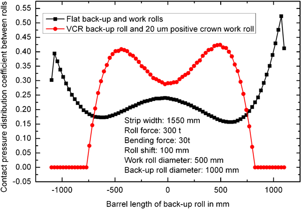
Contact pressure distribution between back-up and work rolls
Assuming that the loaded roll gap is a symmetrical shape, it can be expressed as follows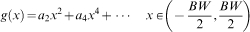

Profile adjustment area of loaded roll gap
From the FEM analysis results described above, the conclusion is that the roll contour configuration of the VCR and the positive crown work roll increases the shape control capability of the temper rolling mill.
Application of roll contour configuration technology
As mentioned before, hot rolled thin gauge strips cannot satisfy the flatness quality required by the customers although they had been processed by the temper rolling mill to correct non-flat strip defects before they are delivered to customers. With the rapid increasing demands on the amount of hot rolled thin gauge strip products, it is a great challenge to make temper rolling mill have not only a good improvement effect on the strip flatness but also a high working efficiency.
Before the roll contour configuration technology was utilised on the temper rolling mill, the maximum amount of strip that could be processed in one schedule was 1200 t. Flatness control became difficult when the amount of thin gauge strips with thickness less than 2·0 mm processed reached 1000 t. When that occurs, the work rolls must be changed and in turn the working efficiency was lowered. From the feedback of customers about the flatness quality of thin gauge 1·6 mm products, it can be concluded that almost all of strips being complained about were processed at the later sections of the temper rolling schedules and most of the unflatten defects were the wavy edges as shown in Fig. 10.
Photo of non-flat defects in thin gauge strip (1·6 mm)
Temper rolling processes were followed and examined when cylinder rolls were used. The detailed parameters including the gauges, rolling quantity, roll forces, bending forces, reduction, tensions and wear contours were collected and analysed, and two examples of rolling schedules can be seen in Fig. 11. For the two schedules, the set-up values of roll force, reduction, and back and front tensions were 150 t, 1%, 15 and 25 t respectively. As shown in Fig. 11a , the bending force was almost used up with the amount processed reaching 1000 t. Non-flat defects still existed after the uncoiling of these strip coils. After temper rolling processes, the wear contours of work rolls were checked and shown in Fig. 11b . Heavier wear took place at roll edges where strip edges contacted and the wear along the roll barrel was not uniform. The heavier wear at the work roll edge had an adverse effect on shape control during the temper rolling process. This verifies the calculation results of contact stress distribution between work and back-up rolls as mentioned before. There are detrimental contact zones at the roll edges beyond the strip width when cylinder rolls were used.
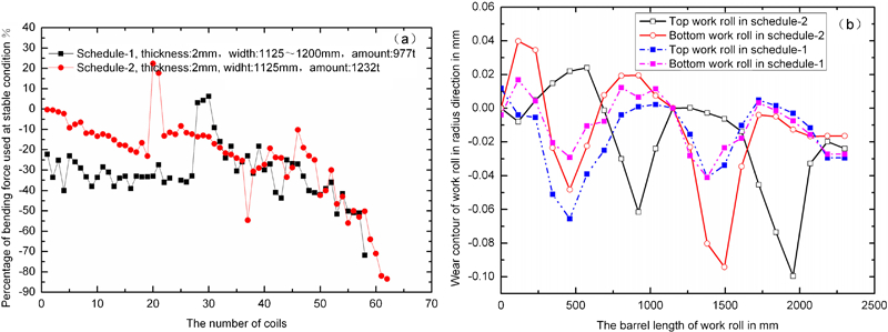
Temper rolling parameters when cylinder rolls were used: a rolling schedules and b wear contours of work rolls
The samples were taken every 10 coils from the first to the 40th in the temper rolling schedule 1 mentioned above in Fig. 11a . Narrow cross-section samples before and after temper rolling were cut at ∼20 m to the head ends of the strip coils. Cross profiles of these samples were measured and comparisons are shown in Fig. 12. The strip crowns after temper rolling are nearly equal to those before temper rolling when cylinder rolls were used, as shown in Fig. 12a . The profile curves before and after temper rolling had almost no change, as shown in Fig. 12b . The profile of the strip was reduced at an equal ratio during the temper rolling process when the cylinder rolls were used. As a result, no flatness improvement occurred because there were equal elongations along the cross-section of the strip. Therefore, both measurements and calculations verified that cylinder rolls on the temper rolling mill have limited function for improving the flatness of a thin gauge strip.
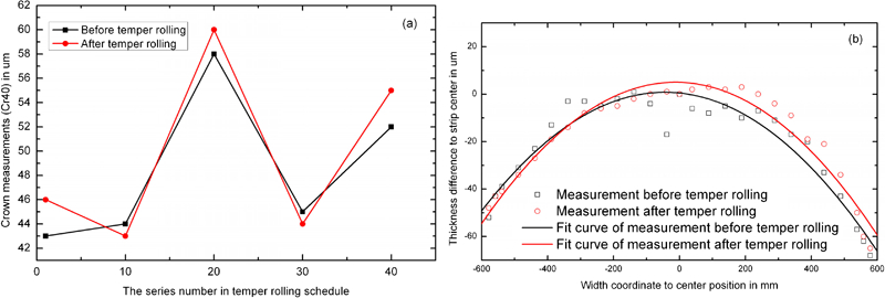
Profile measurements on strips when cylinder rolls were used
To increase the flatness capability of the temper rolling mill, roll contours and configurations shown in Figure 4 Figs. 4 and 5 were applied. In the early testing work, a parabolic positive crown curve with 30 um was adopted on the work roll. Although there was obvious improvement on flatness quality, the problem was that it led to unstable working conditions for the temper rolling mill at the early stage of the schedule. Then the roll contour curve was changed to a sixth order of polynomial with 30 um crown. The testing results were similar to those of the parabolic curve of 30 um crown. In order to avoid the unstable problem, a sixth order of polynomial with 20 um crown was employed to be work roll contour. After two schedules of use it was determined as the optimal work roll contour configuration with the VCR in routine production. The working effects of this kind of roll contour configuration were verified through the same mode as these measurements worked for the cylinder rolls mentioned above.
One example of the temper rolling schedule is shown in Fig. 13. The thickness and width gauges of strips are 1·6 and 1175 mm respectively. Parameters excepting the roll contours for processing these coils were set up same as those of two schedules of cylinder rolls mentioned before. The tonnage for this schedule reached 2000 t. Shown in Fig. 13a , the bending force still had a certain room to be used at the end of the schedule. After the schedule, wear contour of work rolls were also measured before regrinding, as shown in Fig. 13b . The work roll wear was improved not only with the wear amount but also with the symmetry.
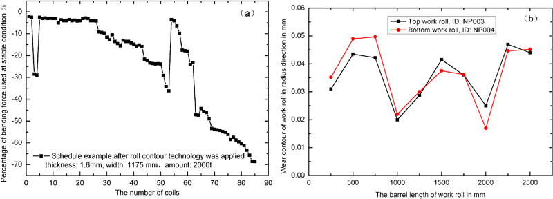
Temper rolling parameters when designed roll contours were used: a rolling schedule example and b wear contours of work rolls
During temper rolling, cross-section samples before and after temper rolling were cut off similar to those before the roll contour configuration was adopted. The across thickness profiles and crowns of these samples were measured and compared and the results are shown in Fig. 14. The strip crowns after temper rolling when roll contour configuration is used has a larger range of change than those when cylinder rolls are used. As a result, the elongation distribution in strip along transverse direction can be changed at a large range through changing the profile of the temper rolled strip. This means that the temper rolling mill has a strong capability to improve the flatness quality as the function of roll contour configuration.
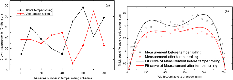
Profile measurements on strips when designed roll contours were used
Qian’an Iron and Steel Company of Shougang Group began to produce thin gauge hot rolling strips for the use of ship containers in 2009. The major issues encountered were that the lower working efficiency and the uncertainty of the shape of the temper rolling process. After the roll contour configuration was employed on the temper rolling mill in April 2010, the amount of thin gauge strip products increased rapidly with increased working efficiency and flatness quality improvements. The production amount of SPA-H strip and the ratio of thin gauge are listed in Fig. 15.
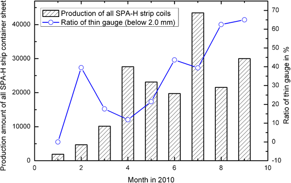
Production amount of thin gauge strip for ship container
The roll contour configuration technology including the VCR contour and the positive crown work roll contour has been utilised on the temper rolling mill for improving the flatness of the thin gauge strip. It has a satisfactory effect on flatness improvement. During the temper rolling process, the mill can usually be stopped to check the flatness in which tensions are released. Figure 16, as a photo taken by camera at the exit of the temper rolling mill under no tension conditions, shows the actual flatness improvement effect of the 1·6 mm strip after temper rolling. On the other hand, this roll contour configuration technology also increases the amount of one processing schedule from ∼1000 to >2000 t. As a result, not only is the strip flatness quality raised by 10% but also the working efficiency is increased. The yield loss of the temper rolling process is reduced from >5 to 0·8% after this roll contour configuration technology was applied. The number of complaint cases for unflatten defects of thin gauge strips was also reduced.
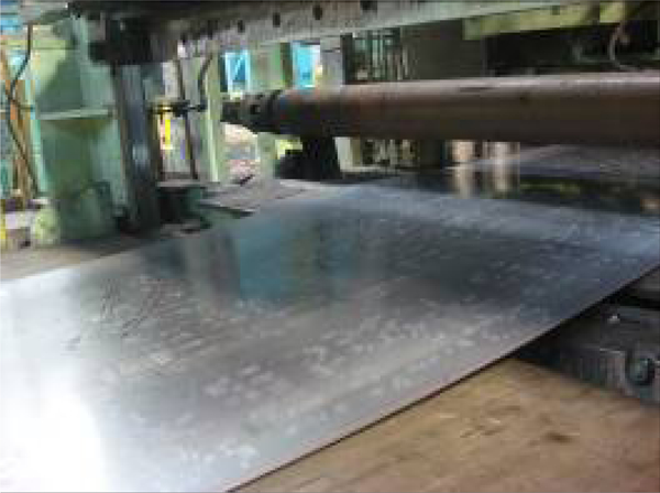
Photo of thin gauge strip flatness after temper rolling
Conclusions
The roll contour configuration technology has the function of increasing the shape control capability of temper rolling mills for thin gauge strips. The roll contour configuration is composed of the VCR contour and the positive crown work roll contour, both of which can be described as sixth order polynomial functions. The roll contour configuration technology can be easily carried out through the grinding roll with a specific contour without upgrading any equipment.
The variable contact back-up roll not only reduces the roll stack deflection and contact pressure concentration between work and back-up rolls, but also increases the shape control capability of the temper rolling mill.
The positive crown work roll contour is adopted to compensate for the roll wear and as a result the processing schedule of temper rolling mill can be extended.
After this roll contour configuration was applied to the temper rolling mill, the flatness quality of hot rolled thin gauge strips was improved by 10% and the working efficiency was also increased.