
Abstract
In the steel plant considered here, direct reduced iron (DRI), produced by the coal based Stelco–Lurgi/Republic–National (SL/RN) process, makes up 50% or more of the total iron charge. The SL/RN DRI samples from a kiln cooler had high nitrogen contents (50–250 ppm, depending on particle size), contributing to elevated nitrogen levels in liquid steel produced in the electric arc furnaces. The proposed mechanism of nitriding of SL/RN DRI involves gaseous nitrogen (present within the rotary cooler) diffusing into the solid bed and is supported by a simple diffusion model. A strong correlation was found between the melt-in carbon content of the liquid steel and the final tap nitrogen content, with melt-in carbon of 0·3%C or higher resulting in nitrogen levels below 50 ppm at tap, even when charging DRI material that is high in nitrogen.
Introduction
Direct reduced iron (DRI) has become a valuable feedstock to the electric arc furnace (EAF). In the last 10 years, the annual worldwide production of DRI has increased by ∼60% to 70 Mt in 2010.1 Direct reduced iron production is dominated by gas based reductant processes like MIDREX (58% of world DRI produced in 2010),1 but coal based reduction remains important in both India and South Africa, where coal is relatively inexpensive and gaseous reductants are not readily available. In total, ∼26% of DRI is produced in rotary kiln coal based processes such as the Stelco–Lurgi/Republic–National (SL/RN) rotary kiln process.1 In this process, ∼1·5 tons of lump ore (−31·5+3·15 mm), 800 kg of coal and 40 kg of dolomite are fed to a kiln to produce 1 ton of DRI. At the kiln exit, the transfer of material is through a transfer chute (closed off from the atmosphere), through which the material falls into a rotary cooler. The DRI produced in the kiln exits at ∼1000°C (the residence time in the kiln is ∼12 h) and is cooled in a water cooled rotary cooler (up to 80 m long; residence time, ∼2 h) to ∼100°C. The kiln atmosphere consists mainly of nitrogen, carbon dioxide and water vapour; the atmosphere in the cooler is expected to be mainly nitrogen.
Nitrogen control in EAF steelmaking can be successfully achieved by applying three principles: using feed materials with low nitrogen levels, preventing absorption of nitrogen from the atmosphere and removing nitrogen during or after steelmaking.2
Many authors have investigated the benefits of having sufficient amounts of carbon in DRI to reduce nitrogen levels in liquid steel during electric steelmaking.3, 4 Carbon, when present at sufficient levels (∼1·8%), yielded substantial improvements in slag foaming5 by the promotion of carbon boil. In addition, trials have also been run on injection of fine DRI material into steel melts to essentially start the carbon boil within the steel melt.6 There needs to be a balance between the amounts of carbon and oxygen present in DRI (1%C balances ∼6%FeO, yielding CO and metallic iron when heated) to promote slag foaming and hence shielding the bath from the atmosphere.
Goldstein et al. 4 showed that when DRI is dropped into a metal–slag melt, that DRI generally does not penetrate the metal, but rather floats on top of the melt (at the slag/metal interface), releasing carbon as carbon monoxide gas, foaming the slag, but not increasing the carbon content of the melt. This implies that the use of DRI to increase the carbon content of a steel melt is limited (if at all possible), yet various plants appear to benefit from using DRI with higher carbon content than that produced via the rotary kiln route.
Since the SL/RN process is a solid state reduction process, with solid carbon as reductant, little carbon dissolves in the sponge iron. The carbon content of DRI produced at the plant considered in this work is <0·15%C,7 considerably lower than that of DRI produced by gaseous reduction processes (such as MIDREX), for which the carbon content of the DRI is between 1 and 2·5% (due to carburisation during cooling in a methane–hydrogen mixture after reduction).8
Plant description
The plant of which production data were analysed in this work uses a large proportion of SL/RN DRI in the feed to the electric furnaces. The typical degree of metallisation of the DRI is 88–90%.
It was found that the nitrogen content of liquid steel tapped was often in excess of 80 ppm by mass, higher than expected (compared with plants using gas based DRI). The aim of the investigation summarised here was to identify reasons for the high nitrogen tap content and to suggest possible remedial measures. As background, a short description of the production process is presented first.
The electric steel plant produces crude steel (with roughly 0·03%C) mainly from scrap and DRI using three EAFs, tapped at ∼1630°C. Each furnace has a capacity of 180 tons, tapping on average 155 tons per heat. On average, the charge mixture is 30% scrap, 50%DRI (the ratio between DRI charged in the basket and that which is charged through the roof is typically 1∶5), 10% hot metal (from a blast furnace) with the remaining 10% including pool iron and other high carbon material. A typical timeline for steel production in these furnaces is shown in Fig. 1; in more detail, the process steps are as follows.
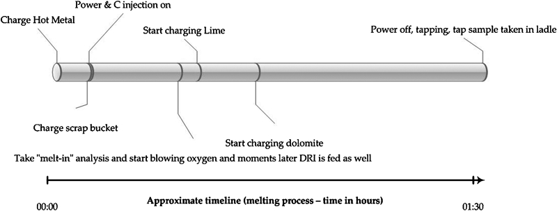
Approximate timeline for steelmaking in EAF as considered in this project
Hot metal, if used, is charged first into the 15–30 ton hot heel, followed by the first basket (containing scrap, DRI fines, defined as ⩽3 mm material, constituting ∼8% of the total metallic charge, slag formers and carbonaceous material and pool iron). After charging the basket, the roof is swung closed, and the power is switched on. Once most of the scrap is molten (heavy scrap can still be left at this stage), the operator takes a ‘melt-in analysis’ of the steel bath. Continuous roof charging of the DRI (with some additional slag formers) is subsequently started while continuing arcing. In total, roof DRI constitutes ∼40% of the metallic charge. The operator starts blowing carbon and/or oxygen into the melt (after taking another steel sample) to aid the formation of a foaming slag by inducing ‘CO boil’. This process continues until the steel is fully liquid and ready for tapping; one last furnace sample is taken to analyse carbon, nitrogen and oxygen levels. Carbon is adjusted to specification, nitrogen is checked (if the levels are elevated, the material might be reclassed as a less valuable steel grade) and the oxygen level is used to assess the amount of deoxidant to be added during tapping. The furnace is subsequently tilted, and tapping commences through an eccentric bottom taphole at the back of the furnace. The aim tapping time is <3 min (on average, 2·5 min is achieved) to limit slag carryover as well as nitrogen pick-up. Following tapping, the liquid steel (containing, on average, 800–1100 ppm dissolved oxygen) is deoxidised with Al, Si or both.
Investigation
Plant data from a typical month’s production were analysed to determine the relationships between the proportion of DRI charged and the tap nitrogen level and between melt-in carbon and tap nitrogen.
The nitrogen content of samples of SL/RN DRI was determined by combustion analysis. To this end, a composite DRI sample was supplied by plant personnel (∼30 kg in total, from two SL/RN kilns). The samples were split into smaller aliquots by cone and quartering and then separated into different size fractions (in the range of −25 mm+212 μm) using a set of Tyler sieves. Aliquots were taken from each size fraction and milled in a swing mill for combustion analysis.
Results and discussion
Relationship between DRI input and tap nitrogen
A month’s tap analyses of three furnaces are summarised in Fig. 2. In Fig. 2, only those heats that did not use hot metal and with adequate slag foaming were considered (the plant uses a system that monitors slag foaming; only heats with well foamed slag for >50% of the duration of the heat were included). Based on these selection criteria, the number of relevant heat analyses was 270 (out of a total of 682 heats).
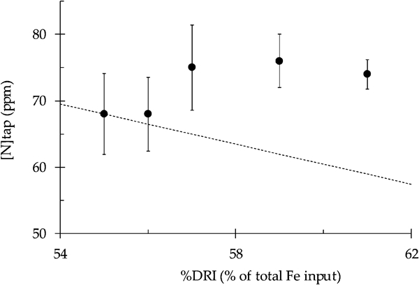
Nitrogen content of liquid steel after tapping from EAFs (samples taken directly after tap, before dispatch to ladle furnace). These are average values for heats consisting of scrap and DRI only. Broken line shows expected trend for case where DRI simply dilutes nitrogen within steel melt and if the DRI contains no nitrogen
It was found that when more DRI is charged to the furnace, the nitrogen levels are slightly higher. This is in contrast with the general EAF experience that DRI charged to an EAF dilutes other nitrogen containing materials (e.g. scrap) to lower the nitrogen content at the tap. From Fig. 2, it can be seen that, for this plant, more DRI charged to the furnace (as a percentage of total metal charge) did not result in a lower tap nitrogen content; the nitrogen content did not decrease along the dilution line (broken line in Fig. 3) as expected.
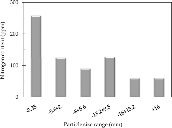
Nitrogen content of different size fractions of SL/RN DRI
Nitrogen content of DRI
Combustion analysis showed that the DRI has a significant nitrogen content (Fig. 3). There is a clear dependence on particle size, with larger DRI particles containing lower amounts of nitrogen. The possible origins of nitrogen are as follows.
Coal contains some nitrogen: the average nitrogen content of all coals listed in the US Geological Survey Coal Quality Database9 is 1·3 mass-% (dry basis). One published source suggests a somewhat higher concentration (∼2%) in South African coals.10 When the coal is devolatilised, N containing gaseous species (notably HCN) are released,11, 12 which could in principle nitride iron. However, volatile release occurs while the solids are heating up before metallic iron has formed:12 no metallic iron is present to be nitrided when volatile nitrogen bearing species are released, and the nitrogen from coal is hence not expected to be a significant source of the nitrogen in the SL/RN DRI product.
Since the freeboard gas largely consists of nitrogen in both the rotary kiln and the cooler, nitrogen gas diffusion into the porous DRI particles can cause nitriding. Although the solid bed is continuously flushed by CO (reaction product), during reduction in the rotary kiln, and no nitrogen pick-up is expected, the reduction rate rapidly decreases once the DRI is cooled (upon transfer to the rotary cooler), causing CO production to cease and allowing nitrogen to diffuse into the solid bed and into the individual DRI particles. It is hence thought that nitriding of the DRI particles occurs during cooling in the rotary cooler, where the flow of CO from the bed is not sufficient to shield the DRI from nitrogen present in the cooler atmosphere. This suggestion was tested with a simple diffusion model, as presented in the next section.
Estimate of nitrogen penetration into solid bed
For the nitriding of metallic iron to occur, gaseous nitrogen needs to diffuse into the solid bed (in the rotary kiln or cooler) against the outward flow of carbon monoxide (which is the main gaseous product of the reduction reaction). Detailed analysis of this mass transfer situation would be quite complex and is beyond the scope of this paper: reaction steps include diffusion of nitrogen through the boundary layer between the solid bed and the freeboard, possible entrainment of nitrogen from the freeboard when the solids tumble down the surface of the solid bed (as a result of kiln rotation), diffusion of nitrogen into the solid bed, pore diffusion of nitrogen into the DRI and solid state diffusion of atomic nitrogen into metallic iron. Instead of attempting to solve this complex mass transfer situation, a simplified static one-dimensional situation was considered to test the basic concept that diffusion of nitrogen into the solid bed is feasible under kiln and cooler conditions.
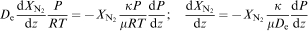
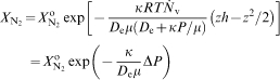
The approach of Tien and Turkdogan,13 developed to assess the diffusion of inert gas into metal oxide–carbon mixtures during reduction, was adapted for this purpose. Tien and Turkdogan derived the relevant relationships from the ‘dusty gas model’; the relationships relevant to the diffusion of CO–N2 mixtures (where the two diffusing species have the same molar mass and hence have essentially the same diffusivities) are as given below.
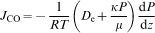
The total flux (due to diffusion and bulk gas flow) in the z direction is as follows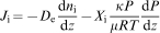
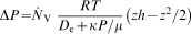
The shape of the concentration profile into the solid bed would depend on the relative efficiency of diffusion into the solid bed and the uptake of nitrogen by the iron (through pore diffusion and diffusion of atomic nitrogen into austenite). A first estimate of the concentration profile in the solid bed can be obtained by assuming stagnant diffusion of nitrogen, that is J
N2 = 0. This would be the case if the nitrogen uptake by the iron (rather than diffusion into the bed) is rate determining. For this case, the flux of carbon monoxide out of the bed is then given by13

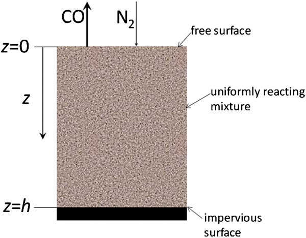
Schematic drawing of physical situation considered for dusty gas calculations
For this situation, the flux of CO (in the z direction) depends on the position within the bed as follows

The following input data were used to evaluate the nitrogen concentration.
The binary diffusivity (in CO–N2 mixtures) was calculated from the equation of Hirschfelder et al.
14,
15 Following Tien and Turkdogan,13 it was assumed that the Knudsen diffusion effect is negligible; hence, the effective diffusivity through the pores of the solids bed is given by
The permeability was calculated from the Kozeny–Carman equation17 assuming spherical particles
The ranges of CO generation rate 
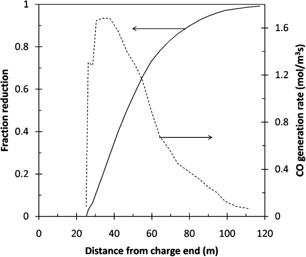
Volumetric generation rate of CO in SL/RN rotary kiln (broken line) as calculated from reduction profile as reported by Venkateswaran and Brimacombe12 (solid line)
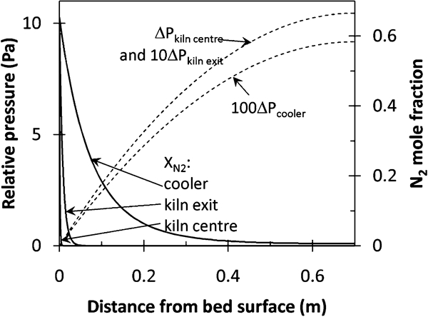
Calculated pressured drop (broken lines; pressure drop for kiln exit and cooler multiplied by 10 and 100 respectively to show these on same graph) and nitrogen mole fraction within solid bed at different positions in SL/RN process
Figure 6 shows that, essentially, no nitrogen penetration into the solid bed is expected halfway along the rotary kiln (where the reaction rate is high), with some penetration towards the kiln exit and significant penetration in the cooler. The pressure increase within the bed can be seen to be affected mainly by the reaction rate and secondarily by the temperature difference between the kiln and the cooler. As a measure of the degree of nitrogen penetration, the position within the bed was determined where the partial pressure of nitrogen in the gas phase would be in equilibrium with 50 ppm of dissolved nitrogen in austenite based on the literature values for nitrogen solubility (the value of 50 ppm is an arbitrary one but chosen to reflect a significant nitrogen pick-up).18 Based on this criterion, the depth of nitrogen penetration into the solid bed at the centre of the kiln is estimated to be 2·2 mm (i.e. less than the diameter of the solid particles), compared with 22 mm towards the kiln exit and 267 mm in the cooler. These values emphasise that the nitrogen penetration depth is approximately inversely proportional to the CO generation rate and that significant nitrogen penetration into the solid bed is expected close to the kiln exit and certainly in the rotary cooler.
Possible approaches to nitrogen control
The results presented in the previous sections show that significant amounts of nitrogen in EAF raw materials lead to higher nitrogen levels at tap and that DRI produced in SL/RN rotary kilns was found to contain as much as 250 ppm N, in contrast with previous assumptions of low nitrogen levels. This is exacerbated by the low carbon content of this type of DRI, too low to enhance carbon boil and slag foaming.
Carbon in the steel bath can contribute considerably to nitrogen control by CO flushing of the bath. This proposed mechanism is supported by data from the plant considered here. Figure 7 presents a scatter plot of the final nitrogen content of steel tapped plotted against melt-in carbon content, as measured after scrap melting (data from 3120 heats, with no filtering of the data, i.e. the heats with hot metal are included). While the scatter plot does not show a clear trend, grouping the data (based on the carbon content) and calculating the mean tap nitrogen (with 95% confidence interval on the mean) for each group does reveal a strong relationship (Fig. 8).
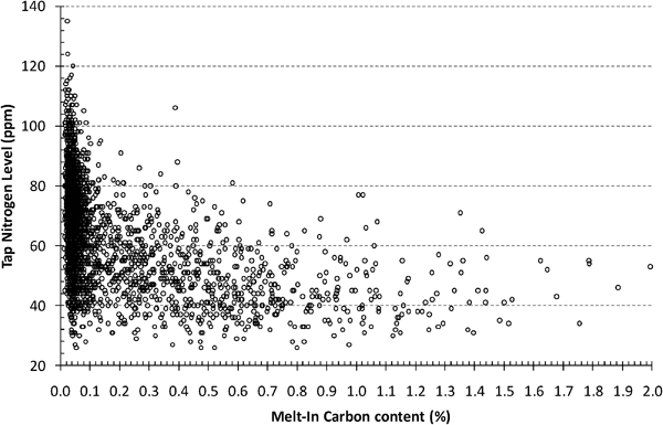
Scatter plot of nitrogen content at tap versus melt-in carbon content
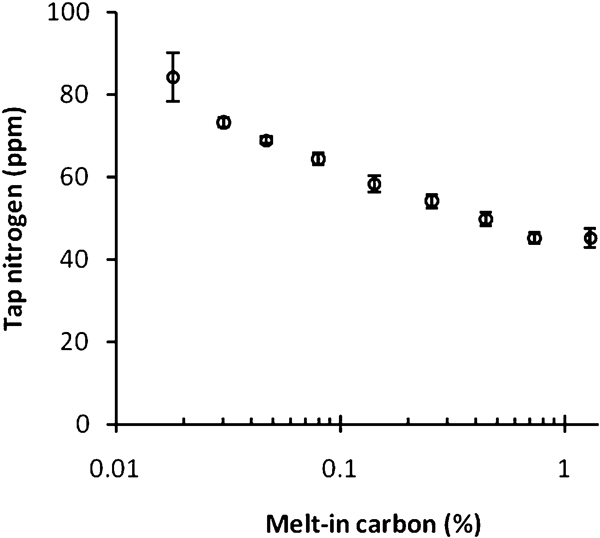
Mean nitrogen content of tapped steel (with 95% confidence intervals); heats grouped by melt-in carbon content
Figure 8 shows that to control the average nitrogen content of steel to below 50 ppm, the carbon content at melt-in should be approximately 0·2–0·3%C. To achieve the required melt-in carbon content, the carbon should be preferably charged in the basket. There have been suggestions of carburising SL/RN DRI at the plant to increase its carbon content, but this option is unlikely to be effective, since most of the DRI is charged through the roof of the furnace. Goldstein et al. showed that in order to realise the benefits of carbon in DRI, it cannot be charged through the roof after slag has formed:4 the low density of DRI, lower than that of slag, does not allow for deep penetration required for the removal of nitrogen from a steel melt.
The SL/RN DRI can be briquetted; as shown in early reports on the development of the SL/RN process,19 a pressure of ∼350 MPa during briquetting produced briquettes with a maximum density of ∼5 t m−3, which is sufficient to penetrate the slag layer. In this case, carburisation of DRI would also be necessary if an increase in melt carbon is to be obtained.
It is hence concluded that carburisation of DRI (which would require installing a carburisation system at the plant using for example coke oven gas) would not necessarily benefit the EAF steelmaking process, unless the majority of the DRI were charged in the basket or briquetting were implemented.
In contrast, the role of carbon boil in removing nitrogen is well established20 and supported by the strong role of melt-in carbon demonstrated in this work. Previously reported plant data indicated that a minimum of 0·3%C removal is required for adequate nitrogen removal through the carbon boil mechanism.20 This required carbon level agrees with the plant data from the current work, as shown in Fig. 8.
Conclusions
Direct reduced iron produced in SL/RN rotary kilns was found to contain as much as 250 ppm nitrogen, in contrast with previous assumptions of low nitrogen levels. Nitrogen is suspected to be picked up during cooling of DRI in a rotary cooler, where the flow of CO gas from the bed is low and the penetration of nitrogen from the cooler atmosphere is possible. Carbon boil during electric furnace steelmaking is efficient at lowering the nitrogen level; to utilise this to achieve a nitrogen level at tap of 50 ppm or less, the melt-in carbon needs to be 0·2–0·3% or higher.
Footnotes
Acknowledgements
The authors thank the AMSA staff for samples, data and information, as well as the Department of Materials Science and Metallurgical Engineering of the University of Pretoria for financial support.