
Abstract
This paper presents a study on the design of a multiheat teeming tundish for heavy steel ingots. The effects of dimensions on liquid steel flow pattern and inclusion flotation were studied by physical modelling, which provided basis for a new oval shaped design. The research demonstrated that increasing the bath depth H and, in particular, tundish length L provided positive benefits for inclusion flotation. To optimise the flow patterns of liquid steel and inclusion flotation, the bath depth should be controlled between 1500 and 2000 mm, and the L/H should be controlled between 2·0 and 2·7. Evaluation of a rotor forged from a large ingot produced using the new tundish indicated that the diameter of single equivalent defects decreased from 2·5 to 1·6 mm, and the total oxygen content decreased by 32% when L/H was increased from 0·73 to 2. Therefore, the new tundish effectively improved the quality of forging.
List of symbols
mass concentration of solution, kg m−3
flowrate, m3 s−1
peak residence time
theoretical time
mean residence time of short circuiting flow

mean residence time
dead volume
mixed volume
plug volume
water volume in the tundish, m3
short circuiting volume
collected amount of particles at the outlet
injected amount of particles to domain
Introduction
For steel ingots larger than 400 t, due to limitations on melting furnace size, multiheat teeming is usually used, as in traditional continuous casting. In the present study, the steel ingots are for 1000 MW nuclear conventional solid rotor forgings. These are very quality critical and have some of the biggest section sizes and the highest technical requirements in the world. Since the rotor weight is 170–180 t, this requires an ingot of 580–650 t, and multiheat teeming of electric arc furnace–ladle furnace–vacuum degassing–vacuum carbon deoxidation, up-pour technology and vacuum casting are commonly used worldwide.1
In the process of multiheat teeming, the tundish acts as an intermediate vessel between ladle and ingot mould, storing liquid steel when the ladle is changed. With the development of tundish metallurgical technology, the function of inclusion removal in a tundish of conventional continuous casting has turned into a key technology for clean steel production. Large capacity tundish, high bath depth and flow control devices are used to enhance the residence time of liquid steel in a tundish and to promote inclusion aggregation and flotation. 2 2,3 In China, large capacity, deep bath round tundishes are mainly used in the production of heavy ingots to meet the requirements of a high casting flowrate. However, the short residence time of liquid steel in these tundishes caused by the short distance from the zone of ladle injection to the outlet and large flowrate does not aid inclusion removal. Therefore, it is necessary to design a tundish for multiheat teeming of heavy ingots with improved inclusion removal.
A number of studies and practices showed that inclusion removal is aided by a liquid steel flow field pattern that includes long residence time, small dead zone fraction and without short circuiting flow.4 – 6 The geometry of the tundish is one of the important factors that affect the liquid steel flow pattern. The research7 indicated that the width/bath depth ratio in a large capacity tundish has no obvious influence on the removal of macroscopic inclusions, so adjusting the tundish length/bath depth ratio becomes an important method to change the geometry size. Some research showed 8 8,9 that with the increase in bath depth, the removal ratio of inclusions gradually increased, and the tundish length L/bath depth H ratio should be kept to >3·5. However, these conclusions relate to continuous casting, so further verification for ingots is still needed.
In this paper, physical modelling was performed to investigate flow field pattern and inclusion removal efficiency in the different designs of multiheat teeming tundishes, including round tundishes with different bath depths and grooved tundishes with different L/H.
Experimental principle and scheme
Experimental principle
According to the similarity principle, physical modelling should follow geometrical similarity, movement similarity and dynamic similarity. In the study of flow modelling, the basic conditions of similarity are geometrical similarity and dynamic similarity. 10 10,11 In this experiment, the geometrical similarity ratio between the model and the prototype was 1∶4. Dynamic similarity requires simulation equality of both turbulent Reynolds and Froude numbers. Owing to the liquid steel and water flows in the modelling area, only the Froude number between the model tundishes and prototype was considered in this work.12 According to such estimate, the similarity ratio of flowrate λ p in the experiment was 0·031. Since the flowrate of the prototype tundish was 51·28 m3 h−1, the converted flowrate of the model tundish was 1·6 m3 h−1
Experimental method and set-up
The experimental set-up is shown in Fig. 1. Blue ink of 15 mL mixed with water was used as tracer and was injected from the long nozzle of a container. The flow field of the tracer was photographed until the fluid was fully mixed. The flow patterns under different bath depths and tundish lengths were then compared.
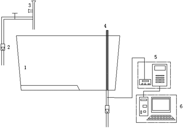
Sketch of experimental set-up
A residence time distribution (RTD) curve was obtained using the ‘stimulus responding’ method. When a steady state flow condition was obtained, 445 mL of NaCl saturated solution was used as tracer and injected into the water stream flowing through the long shroud. One conductivity probe, which was connected to a conductivity meter, was installed below one of the tundish outlets to measure the instantaneous concentration of the tracer as a function of time. The measurement data were input into a computer to calculate the fluid flow characteristics. Based on the correction combined flow model,13 the flow pattern was investigated, and quantitative analysis on the condition of flow field in a tundish was performed to estimate the rationality of tundish structure, that is


Experimental scheme
In order to study the effects of bath depth H, tundish length L and the ratio of tundish length/bath depth L/H on the flow pattern and inclusion removal ratio, different tundish designs were evaluated. As L increased, the tundishes became more oval, not rectangular in shape. For the round tundish, five bath depths were studied (cases 1–5 in Table 1). L was measured at the tundish base. An optimised tundish length/bath depth ratio was selected from the five groups of experiments (see cases 6–10 in Table 1).
Experimental scheme
Experimental results and discussion
Simulation result and analysis of liquid steel flow field
In the experiment, the colouring tracer flowing in the tundish under different conditions was recorded by camera. Only two typical flow patterns are presented in this paper.
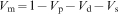
Figure 2 shows the flow patterns in tundishes with different bath depths of 200 and 625 mm photographed at 3, 5 and 7 s. When the bath depth was 800 mm, the ladle stream was divided into two parts after the flow enters the tundish. One stream directly flowed to the outlet because of the drag force from the tundish outlet; the other stream flowed along with the liquid surface and then flowed to the tundish outlet. The velocity of stream near the bottom was obviously faster than that in the upper part of the tundish. When the bath depth was 625 mm, less ladle stream arrived at the bottom of the tundish, and most steel liquid flowed and mixed in the upper part of the tundish. This would reduce the short circuiting flows in the tundish improve inclusion removal.
Flow pattern comparison with different bath depths
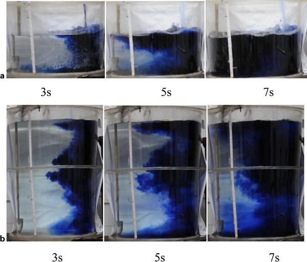
Figure 3 shows the flow patterns in tundishes with different tundish lengths of 459 and 1563 mm photographed at 5, 10 and 15 s. When the length was 1835 mm, the ladle stream was divided into two parts soon after the flow enters the tundish. One stream headed to the outlet from the liquid surface, and the other one reached the outlet from the bottom in 5 s without any upward driving force. When the tundish length was 1563 mm, the ladle stream arrived at the bottom of the tundish, then gradually flowed towards the surface with a faster velocity than that at the bottom, and then finally flowed to the exit. The simulation results showed that the up-flow tendency became more obvious as the length of the tundish increased, which could favour the inclusions moving upward to the surface along with the liquid steel flow and then be absorbed by the fluxes.
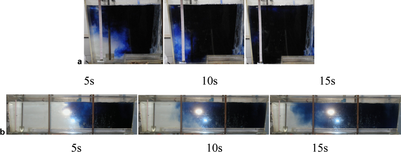
Flow pattern comparison with different tundish lengths
Residence time and flow patterns of fluid
Figure 4 shows the RTD curves in tundishes with different bath depths but the same length. The figure shows that there are two sharp peaks; the first peak indicated the existence of short circuiting flow, and as the depth increased, the peak value of the RTD curves and the short circuiting flow decreased. The reason is that the molten steel from the ladle was divided into two parts: one part flowed straight into the tundish outlet and formed the short circuiting flow; and the other part in the upper part of the tundish then flowed into the outlet and formed the plug flow. The peak value was decreased due to the increase in bath depth.
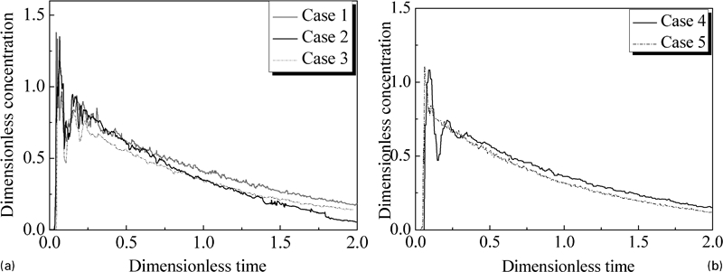
Residence time distribution curves with different bath depths
Figure 5 Figures 5 and 6 show the residence time in the tundish with different bath depths. The results indicated that as the bath depth increased, the longer were the minimum, peak and mean residence times, and the smaller was the volume fraction of short circuiting flow.
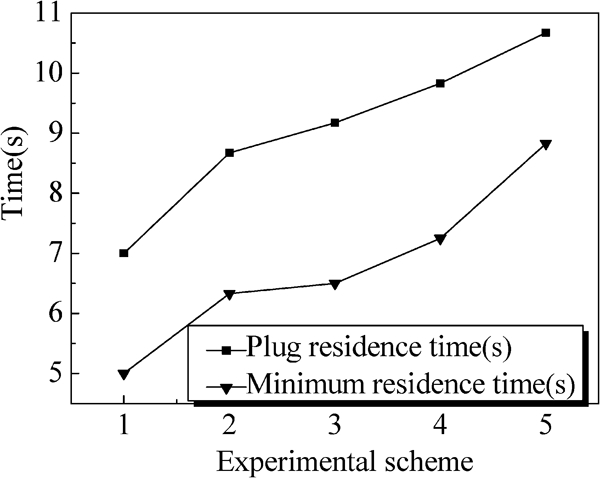
Effect of bath depth on minimum and peak residence times
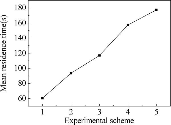
Effect of bath depth on mean residence time
As the bath depth increased, the minimum, peak and mean residence times increased by 80, 57 and 190% respectively. The dead volume fraction and the short circuiting flow volume fraction of molten steel are shown in Fig. 7. When the bath depth increased from 200 to 625 mm, the dead volume fraction increased from 0·22 to 0·35, which decreased the effective volume in the tundishes and the utilisation ratio of tundish.
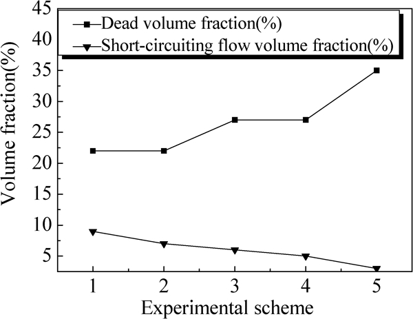
Effect of bath depth on dead region fraction and short circuiting flow volume fraction
It should be noted that in order to avoid vortex formation during the process of changing the ladle, the bath depth of the tundish should be controlled between 1500 and 2000 mm.
Figure 8 shows the RTD curves in tundishes with different tundish lengths but the same bath depth. There is no obvious peak, which means no short circuiting flow. The maximum of dimensionless concentration decreased with the decrease in tundish length. Figure 9 Figures 9 and 10 show the residence time of liquid steel in tundishes with different lengths. Under a certain bath depth, increasing the tundish length would increase the minimum, mean and peak residence times. The conclusion coincides with that of Singh and Koria.16 After increasing the length from 500 to 1563 mm, the minimum residence time was increased 3·3 times, the peak residence time was increased 1·8 times and the mean residence time was increased 1·2 times. The increase in length extended the path of molten steel and prolonged the residence time of molten steel.
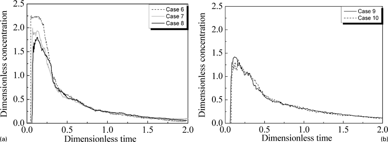
Residence time distribution curves with different tundish lengths
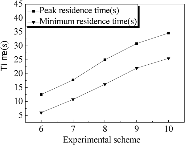
Effect of tundish length on minimum and peak residence times
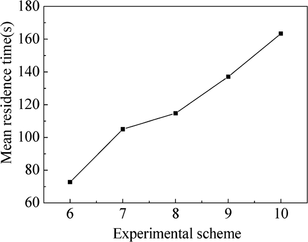
Effect of tundish length on mean residence time
Figure 11 shows the dead volume fraction and the plug flow volume fraction. It can be seen that due to the increase in tundish length, the dead volume fraction was increased, and the plug flow volume fraction increased at first and then decreased. The increased length leads to the increased volume, which delays the mixing time of the steel, increases the volume fraction of molten steel and causes the increase in dead volume. Figure 12 shows the plug flow volume/dead volume ratio. The maximum ratio is in case 7 (0·47). A previous study17 showed that a large plug flow volume/dead volume ratio was beneficial to the flotation of inclusions.
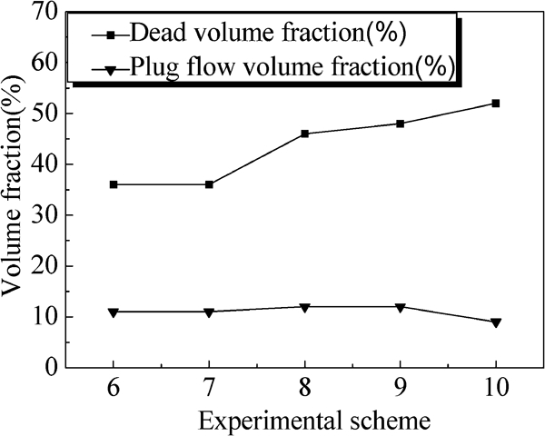
Effect of tundish length on dead volume fraction and plug flow volume fraction
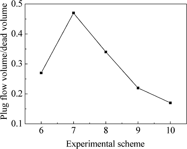
Effect of tundish length on plug flow volume/dead volume
Combining the analysis results of residence time and flow patterns indicated that when the tundish lengths were 737 and 1023 mm and the ratios of tundish length/bath depth were between 2·0 and 2·7, the flow field in tundish was more reasonable. This is mainly due to the smaller tundish length, which would shorten the distance between the inlet and outlet in the tundish. As the depth at the outlet affected the flow conditions of molten steel, and the flow track shortened, the inclusions had less chance to float out. Along with the increase in tundish length, the volume of tundish increased, and the residence time of liquid steel in the tundish increased. However, an excessive tundish volume increased the steel mixing time, which caused the dead zone. When the tundish lengths were 737 and 1023 mm, a large dead zone volume fraction was avoided, but a long residence time provided an advantageous condition for inclusion flotation.
Analysis of inclusion flotation
Figure 13 shows the inclusion flotation ratio in different bath depths and indicates that the ratio increased with the increase in bath depth. The inclusion flotation ratio increased from 42 to 73%, which verified that the increase in bath depth could improve the inclusion flotation. Figure 14 shows the inclusion flotation ratio versus tundish length. When the length increased from 459 mm (L/H = 1·2) to 1023 mm (L/H = 2·7), the inclusion flotation ratio increased from 44 to 79%. While the length increased from 1023 mm (L/H = 2·7) to 1563 mm (L/H = 4·2), the inclusion flotation ratio increased from 79 to 83% and then tended to stable, obviously much less increase than before. The inclusion flotation ratio in different geometric dimension tundishes with the same volume (Fig. 15) indicated that increasing the tundish length would benefit removing the inclusions much more.
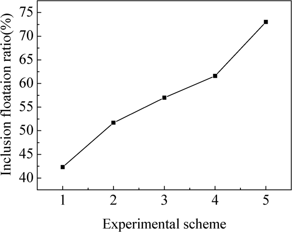
Effect of bath depth on inclusion flotation ratio
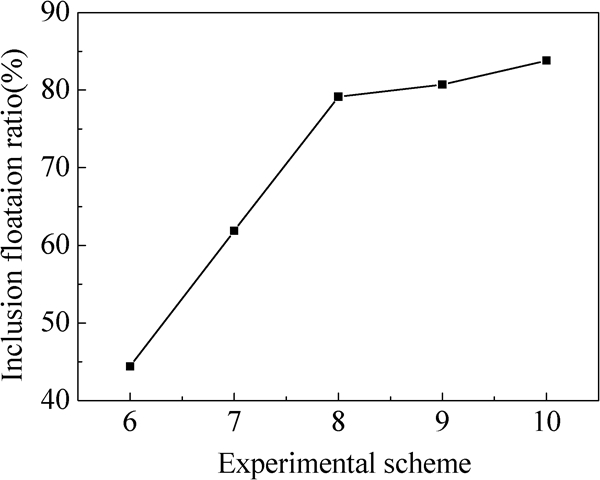
Effect of tundish length on inclusion flotation ratio
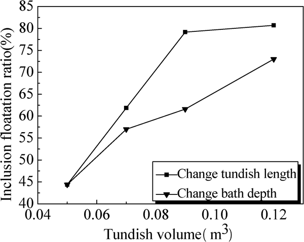
Effect of tundish volume on inclusion flotation ratio
Therefore, combining the analysis of the liquid steel flow field in the tundish with different bath depths and lengths as well as the inclusion flotation ratio, it can be concluded that the bath depth in the multiheat teeming tundish should be set within 1500–2000 mm, and L/H should be controlled between 2·0 and 2·7.
Final tundish design
The design of the tundish needs to take into account the actual application for, in order to accomplish vacuum casting, the tundish to be placed on top of the vacuum chamber and the outlet of tundish is connected to the pouring inlet. To ensure stable placement of the tundish where L/H = 2, the part of the tundish on the vacuum chamber needs to be a round shape.
Taking all the factors above into consideration, a semicircle with a radius of 1000 mm and a semiellipse with a semimajor axis of 3000 mm combined the new 100 t tundishes. The length of the tundish is 4000 mm, and the bath depth is 2000 mm (L/H = 2) (see Fig. 16). Figure 17
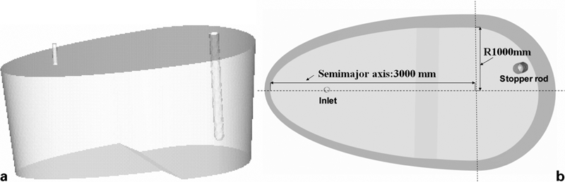
Sketch inside oval tundish
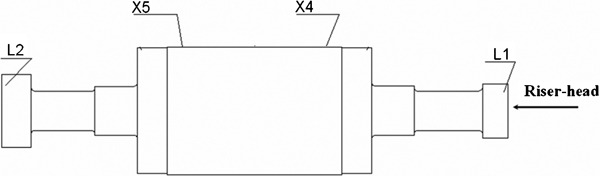
Sampling schematic of 1000 MW rotor (Supplied by China First Heavy Industries)
The tundish, from outside to inside, is divided into steel shell, heat insulation lining, rammed lining, packing lining and working lining. The thickness of the steel shell is 20 mm. The thickness of the heat insulation lining is 5 mm, and the material is high temperature resistant calcium silicate. The thickness of the rammed lining is 80 mm, and the material is spinel castable refractory. The thickness of the packing lining is 35 mm, and the material is magnesia. The thickness of the working lining is 150 mm, and the material is high alumina fire refractory brick.
Results of trial application
In order to investigate the effect of inclusion removal, the original round tundish (L/H = 0·7) and the new tundish (L/H = 2) were used to each cast a 650 t heavy steel ingot for rotor forgings with a diameter of 3 m and a weight of 370 t. The steel grade was 30Cr2Ni4MoV. Comparison of the ultrasonic results of the forgings showed that when using the round tundish, the forging had some single defects with an equivalent diameter of 2·5 mm. However, after using the new tundish (L/H = 2), the equivalent diameter of defects was <1·6 mm, and no intensive defects were observed. Table 2 shows the total oxygen content of the 1000 MW low pressure rotor. It is shown that the total oxygen content reduced by 32% after using the new tundish.
Oxygen content of 1000 MW rotor*/ppm
*X4T-1, X4T-2 and X4T-3 are sampled every 200 mm in the horizontal position. X5T-1, X5T-2 and X5T-3 are in the same way.
Conclusions
Increasing the bath depth and tundish length was beneficial to inclusion flotation. With constant tundish volume, increasing the tundish length was more advantageous to inclusion flotation.
Considering the flow field patterns of liquid steel in the tundish and the inclusion flotation ratio, the bath depth of the multiheat teeming tundish for a heavy steel ingot should be between 1500 and 2000 mm, and L/H should be controlled between 2·0 and 2·7.
Ultrasonic examination results of the rotor forgings showed that after using the new tundish (L/H = 2), the equivalent diameter of single defects decreased from 2·5 to 1·6 mm, and the total oxygen content was decreased by 32%. The quality of the forging product was effectively improved.
Footnotes
Acknowledgements
The authors would like to express their gratitude to the financial support from the science and technology key special subject in China (project no. 2009ZX04014-061-7).