
Abstract
The effects of position of specimens in coils of low carbon steel rod, laying temperature, cooling conditions, aging time, relative humidity and temperature on scale cracking and removal behaviour in bending tests of mechanical descalability have been studied. It was found that laying temperature has a larger effect on scale thickness than cooling rate. Thicker scale results in better descalability. Aging time under ambient conditions after rolling results in little systematic effect on descalability, but considerable variability is attributed to variability in ambient relative humidity. Aging under controlled humidity conditions showed that low humidity is beneficial to descalability and that aging for more than 5 days at ambient temperature has little further effect. Higher aging temperature with constant high relative humidity has a small, but beneficial effect on descalability.
Introduction
The hot rolling of steel rod produces a coiled product capable of being drawn to wire, but possessing an oxidised surface, which has to be removed before the drawing operation. The formation of mill scale on the rod surface is unavoidable during the hot rolling process and air cooling after hot rolling. The composition and thickness of the scale is determined by the finish rolling temperature, i.e. the laying temperature, and the cooling rate before coil formation in the ‘reform tub’.1 Generally, there are three oxide phases present in the scale: wüstite (FeO), magnetite (Fe3O4), and hematite (Fe2O3). The composition and visual appearance of each phase are listed in Table 1.1, 2
Oxide scale composition
Wustite is the softest and most acid soluble of the phases, and hematite is the hardest and most insoluble.1
The influences of the process parameters on scale thickness, or scale weight, have been extensively studied. Sachs and Jay3 examined in detail the scales taken from various stages of rolling using X-ray and metallographic techniques. They found that the mill variables and the cooling rate have a profound influence on the thickness and the structure of the scale, particularly on the extent of decomposition of wüstite below 570°C. Tominaga et al. 2 studied the effects of laying temperature, cooling rates and conditions controlling roll roughness that are necessary to obtain good descaling properties by mechanical descaling. Queiroga et al. 4 studied the influence of cooling conditions (main controlled variables were laying temperature and post-rolling cooling rate) of steel wire rod on scale formation. They found that the high laying temperature was more effective than the slow cooling rate in generating more scale when Stelmor cooling was applied. A paper by Baroux5 reported the influence of process variables on the mechanical descaling properties of high carbon steel.
Gillstrom and Jar6 performed an investigation of mechanical descaling of low carbon steel by reverse bending and brushing as replacement for pickling. They found that the amount of scale remaining after reverse bending depended on the diameter of the bending rollers. After brushing, traces of scale remained in valleys on the surface. It was not possible to clean silicon–chromium alloyed steel by bending and brushing with the roller diameter studied. Geneve et al. 7 studied the descaling ability of different steels and found that it is possible to quantitatively predict the adhesive capacity of the scale depending on the steel composition and on the mechanical and oxidation conditions during hot rolling.
Even though much research has been carried out to find the optimum manufacturing conditions for wire rods with good descaling properties, most of them used the total amount of scale removed and the residual scale after mechanical descaling as the evaluating standard. For mechanical descaling in industry, if the bending strain required for scale removal after certain processing conditions is known, optimum descaling conditions can be quantified, but little work has been carried out in this field.
In a related paper,8 bending methods to determine descalability have been assessed and it has been shown that a simple cantilever bending test, followed by brushing, can be used quantitatively to determine the minimum plastic strain required to achieve full descaling. In the present paper this test is used to assess the influence of a number of process variables on the mechanical descalability of low carbon steel rods.
Experimental
Materials
The steel rods used in this study were supplied by three different rod mills. The compositions of these steels are shown in Table 2. For laying temperature, aging time, relative humidity and temperature tests, basic oxygen steel (BOS) rod samples of 5·5 mm in diameter were supplied by Scunthorpe Rod Mill (SRM). For cooling condition tests, samples of electric arc furnace (EAF) steel of 6·5 mm in diameter were supplied by Cardiff Rod Mill (CRM). For coil position tests, air cooled rods of 14 mm in diameter were supplied by Roundwood Rod Mill (RRM), and Stelmor cooled rods of 5·5 mm in diameter were supplied by SRM.
Chemical compositions of all steel grades investigated and related information
BOS, basic oxygen steelmaking; EAF, electric arc furnace; RRM, Roundwood Rod Mill; SRM, Scunthorpe Rod Mill; CRM, Cardiff Rod Mill.
†Steel grade K08-B contains 0·007%B.
State of materials
In SRM, billets are reheated in a walking beam furnace, then pass through hydraulic descaling before roughing and intermediate rolling. The rod then undergoes another hydraulic descaling before finishing rolling, passes through water boxes and the laying head, and then travels down a Stelmor cooling conveyor and passes into a reform tub. The coil is then compacted, and a compacting band is put on. A number of waps were taken at the trimming stage, i.e. after the rod has travelled down the Stelmor conveyor and passed into the reform tub. The samples for testing were then taken from the back end trim. The coil was at room temperature by the time the waps had been taken to the laboratory, where individual specimens were prepared.
The specimens for the cooling condition tests came from CRM, where the rods were rolled in a two-strand mill, built by Morgan Construction Co. The mill has two Morgan no-twist finishing blocks, followed by water boxes and Stelmor cooling lines. The water boxes are of relatively recent design, and incorporate feedback control, so that it is possible to control the coil laying temperature to within ±10°C of the required temperature. The Stelmor conveyors are 55 m long, with slotted deck plates to distribute the air across the width of the coil. Originally, the air cooling consisted of 5×9 m long zones, each with a single fan rated at 87 600 m3 h−1 capacity. The original zones 1 and 2 on each conveyor have been split into two, and an additional fan (of the same capacity) installed in each.
In RRM, conventional air cooling is applied before coiling in a reform tub.
Scanning electron microscopy (SEM) observation of scale structure
To avoid ‘flare’ from the edge of the oxide scale, rod samples were mounted in the conducting medium of Woods metal. A small sample of rod was sectioned in the longitudinal direction and put in a circular aluminium holder. A small beaker, containing Woods metal, which melts at 70°C, was put in a large beaker containing boiling water. After melting, the Woods metal was poured into the aluminium holder at room temperature and solidified rapidly. After polishing to 1 μm, the sample was polished on silica, washed in warm water, and then immediately put into the sample chamber of a JSM 6400 SEM. Analysis of the elements such as Si and Cu in the scale and steel was carried out on samples of the BOS and EAF steels. Electron back scattered diffraction (EBSD) was used to characterise the multilayer oxide scale.
X-ray analysis of phases in scale
X-ray diffraction was carried out using a Philips PW 1710 diffractometer with Co Kα radiation, a step size of 0·02° and a scan speed of 0·033° s−1. The diffractometer was controlled using Sietronic software. A piece of rod about 20 mm in length was mounted on an aluminium holder using plasticine with the rod sample length perpendicular to the X-ray beam. Even though a flat sample is preferred for the X-ray diffractometer, the 5·5 mm diameter steel rod can be used to analyse the phases in the scale on the surface. The rod sample was scanned for 2θ between 30 and 110°.
Measurement of scale thickness
A sample was mounted in Woods metal, and the scale thickness was measured in an optical microscope Olympus CH-2. For each sample, measurement was made in four different positions along the sample. For each position, five samples were cut from the coil.
Descalability testing
As described elsewhere,8 a cantilever bending test was developed, which gives quantitative measurements of the radius of bend, or the surface tensile or compressive strains required for attainment of full descaling after brushing with a brush with plastic bristles following bending. Briefly, a 300 mm long rod specimen was cut from the coil, which has an initial curvature of ∼500 mm in radius. One end of the rod sample was fixed in a vice and the other end was bent by hand in the direction that increased the original curvature. Before and after the test, the curvatures of the tensile and compressive surfaces of the specimen were determined.
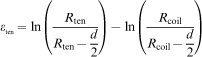
The profile of the bent rod sample was first scanned by using a Cyclone scanner (Renishaw Ltd). After scanning, the continuous profile of the rod was transformed into a geometrical image composed of many very short lines and arcs, and a data file including the coordinates of the points at the end of each line and arc was created within the computer. The arc radius R i, the starting angle θsi and the end angle θei, were then automatically calculated using a computer software Autocad. In this way, the relationship between local radius R i and the distance from the fixed end of the sample D i along the neutral plane was built up continuously in order to be able to plot surface strains versus position.
When R
i(ten) is the local radius of the tensile surface, equation (1) was used to calculate the distance from the fixed end of the sample
When R
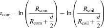
i(com) is the local radius of the compressive surface, equation (2) was used to calculate the distance along the neutral plane and from the fixed end of the sample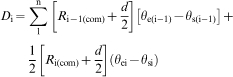
Variables investigated
Scale structure and thickness as function of position in coil
For these tests, two diameters of rods were used. Specimens from rods of 14 mm diameter provided by RRM were cut from different positions in the coil, as shown in Fig. 1. The specimens were taken from three different positions, such as inner (I), middle (M) and outer (O) waps, at different levels, such as front, MA, MB and back of the coil. Overall, samples were taken from 12 different positions in the coil, and were labelled: FO, FM, FI, MAO, MAM, MAI, MBO, MBM, MBI, BO, BM and BI. The rod temperatures at different positions in the compacted coil after the air blow were top 620°C, middle 650°C and bottom 650°C.
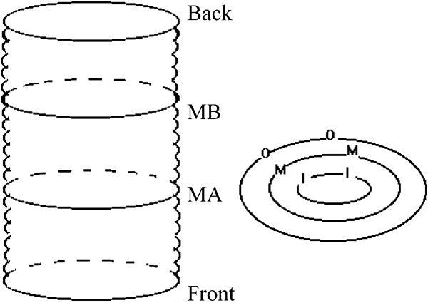
Schematic diagram showing designations for sampling positions of 14 mm diameter rod produced by RRM
Specimens of 5·5 mm diameter rod supplied by SRM were cut from different positions of a ring of the coil. In order to study the effect of the positions in the ring on the scale thickness, centre and edge positions were marked before cutting specimens from the exact symmetry positions in the ring in order to keep the same specimen temperature distribution. Specimens were taken from four positions in the ring, labelled centre, near centre, near edge, and edge.
For each specimen, measurement of scale thickness was made in four different positions. For each condition, five samples were measured to obtain means and 95% confidence limits.
Laying temperature
For laying temperature tests, three specimens of 5·5 mm diameter rod from SRM were taken from each of three laying temperatures, 950, 890 and 830°C.
Cooling condition
The 6·5 mm rods supplied by CRM were cooled under four different conditions in two strands:
laying temperature 900°C, no air on the conveyor
laying temperature 900°C, full air on the conveyor
laying temperature 870°C, no air on the conveyor
laying temperature 870°C, full air on the conveyor.
For each condition, several waps were taken from the two strands, which gave different colours of the rods for the same condition. For each cooling condition, three specimens were taken from each of the two strands.
Aging time
For rod with the laying temperature 950°C, the aging time tests were carried out in the laboratory of SRM. Three specimens were tested for each aging time of 0·5, 1, 2, 4, 8, 16, 24, 48, 72, 96 and 120 h. For the rod with the laying temperature 890°C, a total of 12 waps were taken at the trimming stage. After marking the centre and edge positions of the coil, each ring was cut into four parts. The 0·5 h aging test was carried out in the Scunthorpe laboratory, the other aging tests were carried out at the University of Sheffield. The aging times were 2, 4, 16, 24, 48, 72, 96, 120 h, 15 days and 21 days respectively. At each aging time, five specimens were tested.
Relative humidity and temperature of aging
Different salt solutions were used to control the relative humidity of the atmosphere in a large desiccator for aging rod specimens of K08 steel, at a laying temperature 830°C, supplied by SRM. Distilled water, potassium sulphate (K2SO4), sodium chloride (NaCl), sodium iodide dihydrate (NaI.2H2O) oversaturated salt solutions and silica gel were used to generate 100, 97, 70, 40 and 5% relative humidity respectively. Warm water (∼40°C) was used to make a salt solution. Salt was added until no more salt could be dissolved. When the water had cooled to room temperature, the oversaturated salt solution was placed in a container in the desiccator at room temperature. Specimens 250 mm long were cut from the coil with an initial curvature forming the coil diameter of ∼1 m, and three specimens were tested for each aging time of 1, 2, 3, 4 and 5 days.
For other tests, the desiccator was put into an oven in order to compare the effect of air with 97% relative humidity at 30 and 46°C, after holding times of 0·5, 1, 2, 3, 4, 5 and 6 days. After a specimen was taken out of the oven, it was cantilever bend tested immediately it had cooled to room temperature. For each condition, one specimen was tested.
Results and discussion
Characterisation of oxide scale
Figure 2 shows a scanning electron micrograph of a longitudinal section of rod supplied by SRM, with a laying temperature 890°C. Two layers can be seen. By EBSD, the top layer was identified as magnetite and the bottom layer as wüstite.9 Figure 3 shows the result of X-ray analysis of the scale. It reveals that there are three phases in the oxide scale, i.e. hematite, magnetite and wüstite. Because the hematite layer is too thin to be detected by the SEM used in this project, only the two thicker layers can be seen by the SEM and EBSD.
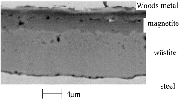
Image (SEM) of longitudinal sample of rod supplied by SRM: laying temperature 890°C
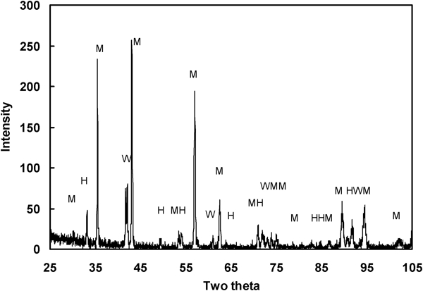
X-ray analysis of scale: M: magnetite; H: hematite; W: wüstite
Variation of scale thickness at different positions in coil
Figure 4 shows the variation of mean scale thickness with position of the sample in the coil from RRM. Clearly, the scale thicknesses of the samples taken from the different levels and different positions of the coil are significantly different. In RRM, the coil is cooled by air blown into the centre of the coil from the bottom. Because the temperature distribution is complicated, it is difficult to draw any conclusion about the reasons for the variations in scale thickness.
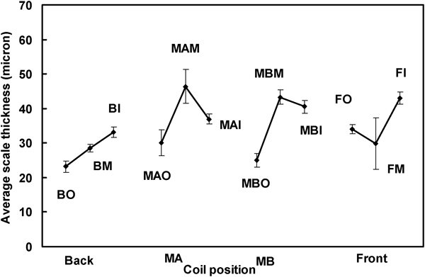
Effect of coil positions on scale thickness on 14 mm diameter rod produced by RRM: four measurements made on five samples taken from each position
Figure 5 illustrates the relationship between the mean scale thickness and the positions of samples in a ring of coil from SRM. In this mill, cooling is by the Stelmor process and can be closely controlled. From Fig. 5, it is seen that the scale thickness at the edge of the coil is greater than that at the centre of the coil. This agrees with the temperature distribution in the coil in the Stelmor process. However, from Fig. 5, the difference is less than the 95% confidence limit of five samples with four measurements on each sample.
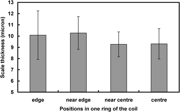
Effect on scale thickness of position in one ring of coil after Stelmor cooling from laying temperature of 890°C: four measurements on five samples taken from each position
Influence of scale thickness on descalability
Oxide scale is repeatedly formed and removed during hot rolling, so the scale remaining on the wire rod at the stage of laying is negligible. Therefore, the laying temperature and cooling rate after laying have the largest effects on the formation of scale. It can be seen in Fig. 6 that as the laying temperature increases, the scale thickness increases. Figure 7 shows the variation of true strain for 1 and 100% scale removal with laying temperature. It reveals that with the increase in laying temperature, the critical strains for 1 and 100% scale removal in tension and compression both decrease significantly.
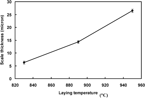
Relationship between laying temperature and scale thickness: four measurements made on five samples in each case
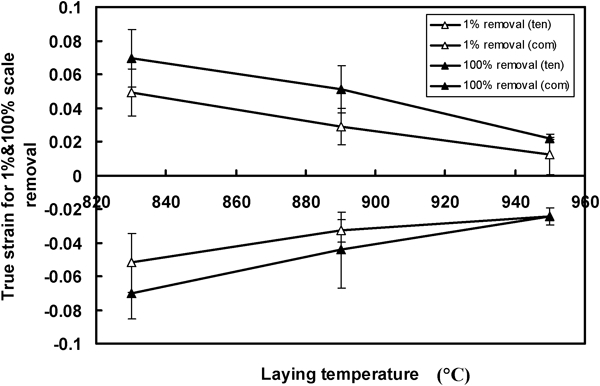
Relationship between laying temperature and true strain for 1 and 100% scale removal
The effects of cooling condition on the mean scale thickness and on the true strain for 100% scale removal (plus 95% confidence limits) are plotted in Fig. 8. It can be seen that as the cooling rate decreases, scale thickness increases, and the true strain for 100% scale removal decreases.
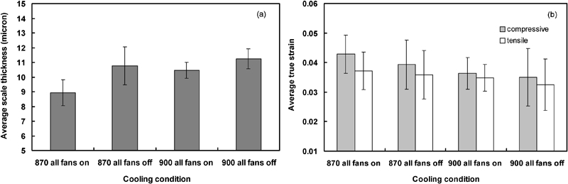
Effect of cooling conditions on a average scale thickness and b average true strain for 100% scale removal
Oxide scale displays brittle characteristics, at least at intermediate and room temperature,10 and brittleness is regarded as a size dependent concept.11 Figures 6 8 show this, i.e. the thicker the scale, the easier the mechanical descaling. However, a too high laying temperature and a too low cooling rate produce thick oxide scale and lead to more metal loss, which is not wanted by the wire industry.
Two phenomena may happen during the cooling process. One is the scale thickening, the other is phase transformation from wüstite to magnetite. For the coil supplied by SRM, the cooling rate <700°C in the Stelmor process is 13 K s−1 at the centre and 7 K s−1 at the bunched edges of the coil. For these cooling conditions, magnetite was not found at the scale/metal surface. It was also observed that a higher laying temperature led to cleaner descaled rod surfaces. For the samples supplied by CRM, and for cooling condition with all fans off in the Stelmor process, magnetite is found by EBSD at the boundary between the scale and metal on the descaled rod surfaces with laying temperatures of 870 and 900°C. The transformation from wüstite to magnetite at the interface between scale and metal relaxes the residual stress at the interface2 and worsens the descalability of the rod. After descaling, a very thin layer of scale (<1 μm) is left on the rod surface.
Aging time
Figure 9a shows the variation of the mean true strain for 100% scale removal (plus 95% confidence limits), with the aging time for coil with a laying temperature of 950°C. It suggests that aging time has some effect on scale removal, but the effect is relatively small. There are some benefits in 8 and 120 h aging compared with 20–40 h, but aging for 8 h after rolling is not a practical time for industry. Figure 9b shows the relationship between the true strain for 100% scale removal (plus 95% confidence limits) with the aging time determined for a laying temperature of 890°C. Again, the effects of aging time are small, with possible benefit in aging for 48 h, and little change after 5 days.
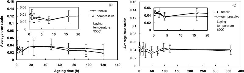
Effect of aging time on average true strain for 100% scale removal for laying temperatures of a 950°C and b 890°C
From Fig. 9, it can also be seen that the curves are wavy. In fact, these results may involve the effect of humidity, because the aging time tests were performed in the open air in the laboratory at the University of Sheffield in December and lasted nearly one month. From the recorded weather data, the relative humidity averaged ∼70% for that period, but its variation within 1 day could be 20–30%, e.g. when it was raining, the relative humidity was ∼70%, but when it was not raining on the same day, the relative humidity was around 50–60%. Furthermore, aging at room temperature could only relax a very small part of the residual stress, which formed during the cooling of the rod and was relatively small, so variations in relative humidity could account for the wavy nature of the data in the aging time tests.
Relative humidity and temperature
Figure 10 illustrates the effect of relative humidity on the descalability of K08 steel rod. From Fig. 10a it can be seen that for ∼5% relative humidity, as holding time increases, the strain for 100% scale removal decreases significantly for 4–5 days. From Fig. 10b , it is seen that for 40% relative humidity, aging time has little effect on the strain for 100% scale removal. Figure 10c reveals that, for 70% humidity, as holding time increases the strain for 100% scale removal reaches a maximum on the fourth day. From Fig. 10d , for 100% relative humidity, there is the same trend as that shown in Fig. 10c . Figure 11 shows the effect of holding time at 30°C and at 46°C with a high relative humidity of 97% on the strain for 100% scale removal. From Fig. 11, the holding time for the maximum strain for 100% scale removal is the third day. The relationship between relative humidity and true strain for 100% scale removal after holding for 5 days is shown in Fig. 12. This reveals that as relative humidity increases, the true strain increases by about a factor of 2, which means that the descalability decreases. Higher oven temperature at a high humidity has a relatively small effect on the strain for scale removal, but the effect is beneficial.
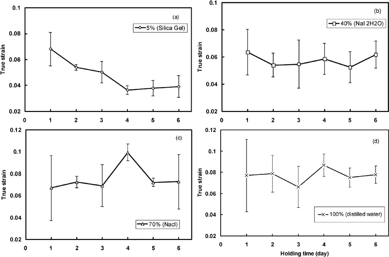
Effect of holding time at room temperature with different levels of relative humidity on strain for 100% scale removal
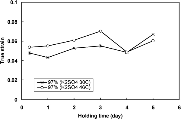
Effect of holding time at 30 and 46°C with relative humidity 97% on strain for 100% scale removal
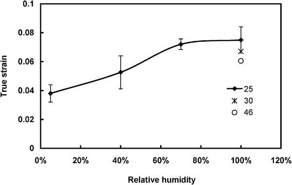
Dependence of true strain for 100% scale removal on relative humidity after holding for 5 days
Descaling is a complex process involving crack generation through the scale and subsequent scale spallation. In finite element modelling of the process13 the critical strain for crack generation was considered to depend linearly on the fracture toughness of the scale, inversely on Young’s modulus and inversely on the square root of the depth of crack-like defects in the surface of the scale. The model captures many of the observed features from the experimental bend tests, but does not specifically explain the effect of humidity on descalability. It is unlikely that the high humidity will change the surface roughness or the porosity of the scale to account for the magnitude of the observed effect on descalability. Increased porosity does reduce the effective Young’s modulus11, 12, 14 – 16 and so would increase the critical strain, but a factor of 2 increase in the strain would require a major increase in porosity, which is not observed. Also, larger pores can act as defects to reduce the fracture strain.17 It is therefore concluded that humidity determines the extent of hydration of the scale, which increases its fracture toughness.
From this viewpoint, the phenomena in Figs. 10 and 11 can be explained as follows. At 25°C hydration, or dehydration in the case of low humidity (Fig. 10a ), takes about 4–5 days to reach its equilibrium level. As expected for a diffusion controlled phenomenon, this time is reduced at higher ambient temperature (Fig. 11). Once equilibrium hydration with the relative humidity has been attained, longer aging times have little effect on descalability.
Conclusions
The thickness of the scale at different positions in a conventionally air cooled coil is different.
As the laying temperature increased, the scale thickness increased and the strain required for 100% scale removal decreased.
At the same laying temperature, as cooling rate decreased, scale thickness increased and the strain required for 100% scale removal decreased.
Aging time under ambient air conditions had a relatively small effect on the strain required for 100% scale removal.
Relative humidity had an effect on descalability, which depended on the aging time. Beyond a critical time, e.g. after 5 days at room temperature, increasing humidity approximately doubled the strain required for 100% scale removal. Longer aging times had little further effect.
Temperature of aging for longer than the critical time has a relatively small, but beneficial effect on strain for 100% scale removal.
Footnotes
Acknowledgements
The authors are grateful to the member companies of the Materials Forum, The University of Sheffield (Corus Long Products, now a subsidiary of Tata Steel, and Tinsley Wire Ltd) for their financial and material support of this project and for their technical input.