
Abstract
A numerical method has been employed to investigate the flow field and mixing characteristic in the Rheinsahl–Heraeus (RH) degasser with side–bottom blowing. The numerical results showed that stream flows in the up snorkel, the vacuum chamber, the down snorkel and the ladle form a large rectangular circulation zone in the RH degasser with side–bottom blowing, which can enhance the circulation flow rate effectively. For an RH with side–bottom blowing, when the included angle of the line between bottom blowing location and ladle centre and the line between two snorkels is zero, the circulation flow rate increases initially with increasing dimensionless distance between the bottom blowing location and the ladle centre and then decreases, while the mixing time increases with increasing dimensionless distance. On the other hand, when the dimensionless distance is 0·2, both the circulation flow rate and the mixing time decrease with the increasing included angle initially, reach their minimum value and then increase. The optimum values for the dimensionless distance and the included angle to achieve large circulation flow rate and small mixing time are 0·2 and π/4 in the present work.
Introduction
Recently, the demand for ultralow carbon steel has increased significantly. As a main metallurgical reactor for reducing the carbon content in steel, the Rheinsahl–Heraeus (RH) process plays a very important role in the refining process for degassing, mixing and decarburisation before the continuous casting process.1 – 3 In addition to degassing and decarburisation, the RH degasser is also an important metallurgical reactor for inclusion removal after deoxidisation.4
During the RH process, temperature drop is one of the inevitable issues due to the long treatment time. Therefore, aluminium addition or post-combustion of carbon monoxide with oxygen has been employed to compensate for the temperature drop of liquid steel.5, 6 Excess oxygen from the top blowing should be removed by inclusion floatation, but this would prolong the treatment time inversely. 4 4,7 Therefore, it is of great importance to improve the RH productivity rate in order to shorten the treatment time. By increasing the circulation flow rate, not only the mixing time can be decreased but also the decarburisation, degassing, alloying and inclusion removal rate can be enhanced.
Many researches have shown that the circulation flow rate is determined mainly by the geometric parameters of RH equipment on the condition of certain vacuum degree and side blowing gas flow rate.8 – 12 Since the bubble trajectory length is restricted by the up snorkel, the circulation flow rate can hardly be increased after reaching its saturation value.7, 8 Thus, to increase the RH saturation circulation flow rate becomes the controlling step for improving the productivity of the RH refining process.
In order to increase the circulation flow rate in the RH degasser, many investigations have been conducted in recent years. The first measure is to modify the parameters of the immersion snorkels, such as increasing the diameter of the up and down snorkels simultaneously,13 using oval shape snorkels to replace round shape snorkels,10 using three up and one down snorkel,14 two up and one down snorkel or one up and two down snorkels,12 etc. The second method is to apply an electromagnetic field around the up or down snorkel, e.g. applying rotating magnetic field around the up snorkel15 and applying travelling magnetic field around the up or down snorkel.16 With the help of the electromagnetic force, the liquid steel can be accelerated to increase the circulation flow rate. The third method is to blow additional argon gas, e.g. blowing argon gas through bottom of vacuum chamber,17 bottom of ladle18 and so on.
However, either changing the structure of the up and down snorkels or adding electromagnetic equipment is expensive and inconvenient. Therefore, ladle bottom blowing is one of the effective and feasible measures to increase the circulation flow rate and shorten the mixing time. However, it should be noted that the flow field and the mixing phenomena in the RH degasser with side–bottom blowing would be very complicated.
As shown in Fig. 1, the ladle bottom blowing position can be calculated by two dimensionless parameters: one is the dimensionless distance L/R between the bottom blowing location and the ladle centre, and the other is the included angle θ of the line between the bottom blowing location and the ladle centre and the line between two snorkels. It should be noted that the flow field and mixing phenomenon would be affected greatly by the ladle bottom blowing position.19 Thus, the purpose of the present work is to clarify the effect of ladle bottom blowing position on the circulation flow rate and the mixing mechanism in the RH degasser on the basis of the developed model concerning gas–liquid flow and tracer transport behaviour in the previous work.9
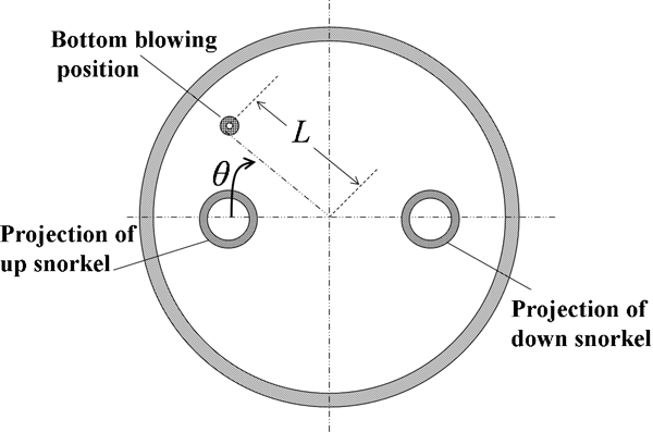
Schematic of bottom blowing location in ladle of RH degasser
Mathematical model
The algebraic slip mixture model can model the gas–liquid flow in the RH degasser and has been validated by experimental data from a water model and actual plant trials in previous work.9 The model for fluid flow and tracer transportation in the RH degasser is based on the following assumptions:.
the fluids in both gas and liquid phases are Newtonian, viscous and incompressible, and the fluid flow is at steady state
the effect of top slag on fluid flow is neglected, and the free surfaces in the ladle and vacuum chamber are assumed to be flat
the bubbles are spherical, and their sizes are constant9, 14
the fluid flow in the RH degasser is an isothermal process.20, 21
Governing equations
The model is composed of continuity and momentum equations for the mixture and volume fraction equation for the dispersed phases.22 Moreover, the k−ϵ model is used to model the turbulent flow in the RH degasser. Finally, the equations of the model are formulated as follows.
Continuity equation

The volume fraction equations for gas and liquid phases are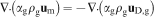

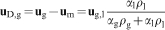
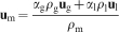
The momentum equation for the mixture is
Turbulence model
The equation for turbulent kinetic energy is expressed as
Tracer transport equation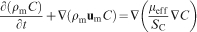
Boundary conditions
The symmetry boundary condition was imposed on the free surfaces in the ladle and the vacuum chamber. For the nodes at the refractory walls, the velocity components were set to zero, the normal gradients of pressure and gas volume fraction were also set to zero and the wall function method was applied at the nodes near the wall. Moreover, the velocity of gas phase at the nozzle is computed by related parameters such as gas flow rate, etc. The bubbles reaching the free surface were assumed to escape at their flotation velocity. Furthermore, the dimensions of RH degasser and calculation conditions are listed in Table 1.
Dimensions of RH degasser and calculation conditions
Solution method
The finite volume method has been employed to solve the governing differential equations. With the SIMPLE algorithm proposed by Patankar and Spalding,24 the differential equations were solved by iteration until the value of the root mean square normalised residual taken over the whole domain for variables was <10−5, and the global imbalances, which means the ratios of the difference between the total input gas mass flux and the total output gas mass flux to the total input mass flux, were <0·1%. The model equations were solved with the CFX 12·1 code on a mesh containing 700 000 nodes. Grid sensitivity experiments were conducted in order to make sure that the solutions were not spurious artefacts of poorly resolved grids. In order to get more detailed information in the two-phase domain, a densely packed grid was applied in the snorkels and vacuum chamber.
Results and discussion
As shown in Table 2, in order to find the optimum ladle bottom blowing position that can yield the maximum circulation flow rate and the minimum mixing time in the RH degasser with side–bottom blowing, the effect of the bottom blowing location, based on a wide variation of the parameters (L/R and θ), on the circulation flow rate and the mixing time in the RH degasser was investigated.
Parameters of ladle bottom blowing location in RH degasser
Figure 2 shows the calculated velocity field in the RH degasser without bottom blowing on the condition of 1400 NL min−1 side blowing gas flow rate. The liquid steel flows upwards due to the effect of the buoyancy force of the gas bubbles injected from the up snorkel, then spreads around and forms two recirculation zones in the vacuum chamber. Finally, the liquid steel flows down into the ladle and forms two large recirculation zones. As can be seen in the sections of B−B, C−C and D−D, the turbulent flow at the free surface of the vacuum chamber and ladle bottom is drastic, while the turbulent flow at the free surface of the ladle is quite weak.
Flow field of different sections in RH degasser without bottom blowing
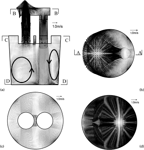
Figure 3 shows the flow field in the RH degasser when the side blowing gas flow rate and the bottom blowing gas flow rate are 1000 and 400 NL min−1 respectively. Since the dimensionless distance and the included angle are 0·2 and 0, the bottom blowing location is near the up snorkel. Comparing Fig. 2a with Fig. 3a , it can be seen that the large circulation zone disappears due to the gas–liquid plume induced by the ladle bottom blowing. Moreover, two smaller circulation zones appear, and it is also in favour of mixing in the ladle. In addition, Fig. 3a also shows that the stream flows in the up snorkel, the vacuum chamber, the down snorkel and the ladle form a large rectangular circulation zone which can effectively enhance the circulation flow rate in the RH degasser. On the other hand, Fig. 3c also shows that the velocity at the free surface of the ladle above the gas–liquid plume increases greatly on the condition of ladle bottom blowing. Thus, some measures should be taken to avoid slag entrapment in the RH degasser with side–bottom blowing.
Flow field of different sections in RH degasser with side bottom blowing (L/R = 0·2, θ = 0)
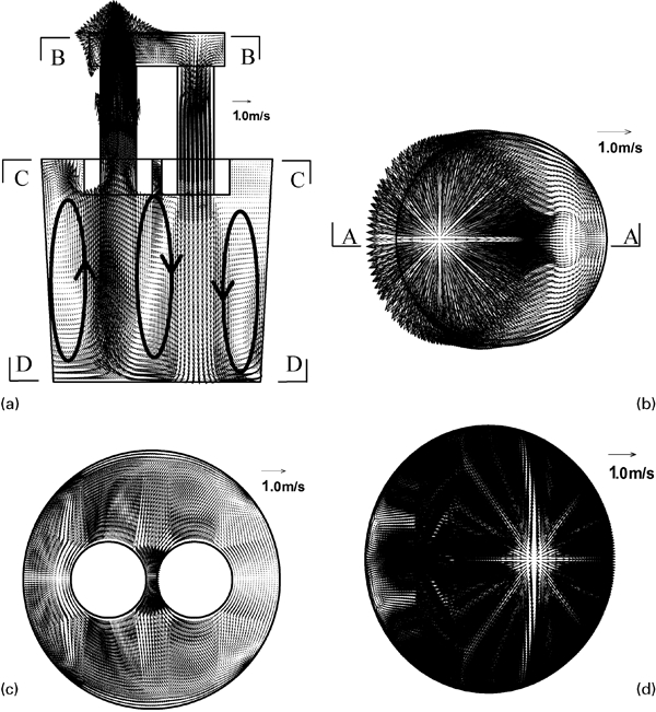
Figure 4 shows the turbulent kinetic energy distributions in the RH degasser with and without ladle bottom blowing. Figure 4a shows that the maximum turbulent kinetic energy is mainly near the free surface of the vacuum chamber, and the turbulent kinetic energy at the up snorkel centre is much greater than that near the sidewall. The higher turbulent kinetic energy can promote collisions and coalescences among inclusions and enhance the inclusion removal rate.
Predicted distribution of turbulence kinetic energy at main plane in RH degasser
Figure 4a also shows that for the condition of without ladle bottom blowing, the turbulence kinetic energy is very uniform with the value of ∼0·003 m2 s−2 in the ladle, so the mixing in the ladle is relatively weaker in contrast with that in the snorkel and the vacuum chamber. On the other hand, Fig. 4b shows that on the condition of ladle bottom blowing, the turbulence kinetic energy under the up snorkel in the ladle rises to 0·57 m2 s−2, while in other regions, the gas liquid plume in the ladle rises to 0·01 m2 s−2. Thus, a better mixing can be obtained on the condition of ladle bottom blowing. In addition, since the overall argon gas flow rate is 1400 NL min−1, Fig. 4 shows that the maximum turbulence kinetic energy decreases in the RH degasser when ladle bottom blowing is adopted.
Figure 5 shows the total pressure distributions in the RH degasser. Here, the total pressure is the sum of the static and dynamic pressures. Moreover, the static pressure is determined by the height, while the dynamic pressure is determined by the velocity. If the height is the same, the greater the fluid velocity, the greater the total pressure. Since the static pressure is much greater than the dynamic pressure in the ladle, the isolines of total pressure in the RH are almost parallel to the ladle bottom. Furthermore, with increasing height, the static pressure deceases gradually, and the dynamic pressure becomes more dominant, so the reverse ‘V’ distribution of total pressure can be found in the up snorkel.
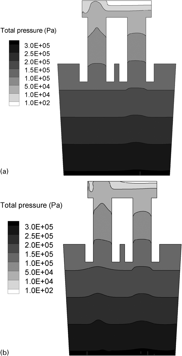
Predicted distribution of total pressure at main plane in RH degasser
On the other hand, since the velocity of liquid steel at the gas–liquid plume in the ladle is greater because of the buoyancy force of bubbles in the case of ladle bottom blowing, the total pressure at gas–liquid plume in the ladle is greater than that at other regions if the height is the same, as shown in Fig. 5b .
As shown in Fig. 6, in order to study the mixing characteristic in the RH degasser with side–bottom blowing, the tracer was added at the centre of the free surface in the vacuum chamber. The junction of the sidewall and the base of ladle, the junction of the sidewall and the free surface of the ladle and the centre of two snorkels in the ladle are the relatively slowly mixing regions, and stagnant flow can also be observed in these zones. Therefore, eight monitoring points (A–D_top and A–D_bottom) were placed around the junction of the sidewall and the base of the ladle and the junction of the sidewall and the free surface of the ladle, while two monitoring points (O_top and O_bottom) were placed at the centre of the free surface and the bottom of the ladle.
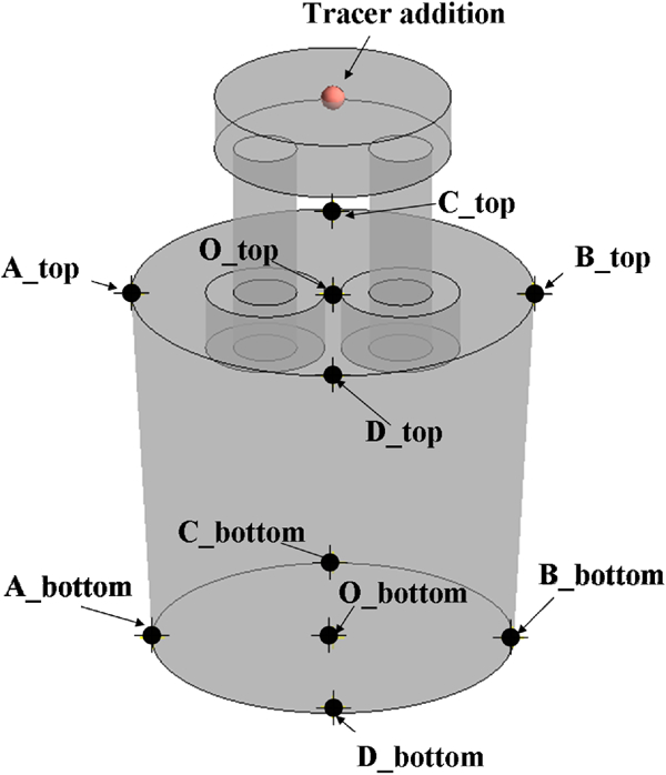
Monitoring points for tracer concentration in RH degasser
As shown in Fig. 7, C(t) is the tracer concentration in the RH degasser, and C(∞) is the average tracer concentration after sufficient mixing. Thus, the tracer dimensionless concentration can be expressed by C(t)/C(∞). It can be found that the tracer dimensionless concentration varied much more slowly at the free surface of the ladle than that at the ladle bottom in the RH degasser without bottom blowing. In contrast with the RH degasser without bottom blowing, the tracer response time and the time for peak value can obviously be shortened in the RH degasser with side–bottom blowing. For example, the tracer response time at monitoring point A_top decreases from ∼35 to 8 s, while the time for the peak value decreases from ∼45 to 15 s. Thus, it can be concluded that bottom blowing can improve the mixing efficiency in the RH degasser.
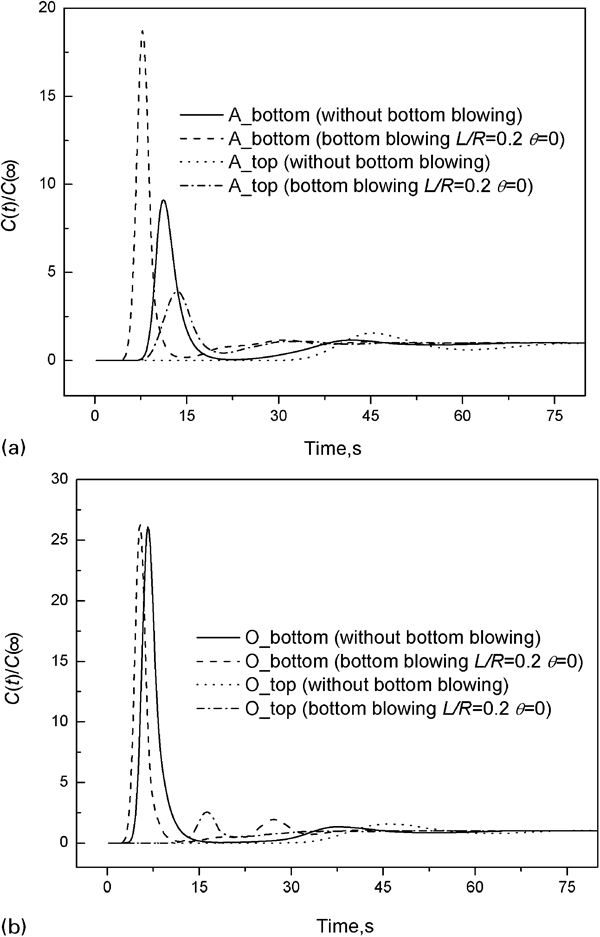
Variation of tracer dimensionless concentration at different monitoring points with time
Figure 8 shows that for the RH degasser with bottom blowing, on the condition of zero included angle, the circulation flow rate increases with increasing dimensionless distance; first, it reaches its maximum value when L/R = 0·2 and then decreases. The main reason for this phenomenon is that with decreasing distance between the gas–liquid plume and the up snorkel, the more liquid steel flows into the up snorkel, and the circulation flow rate increases. On the other hand, with decreasing distance from the ladle sidewall, the less liquid steel flows into the up snorkel, and the circulation flow rate decreases.
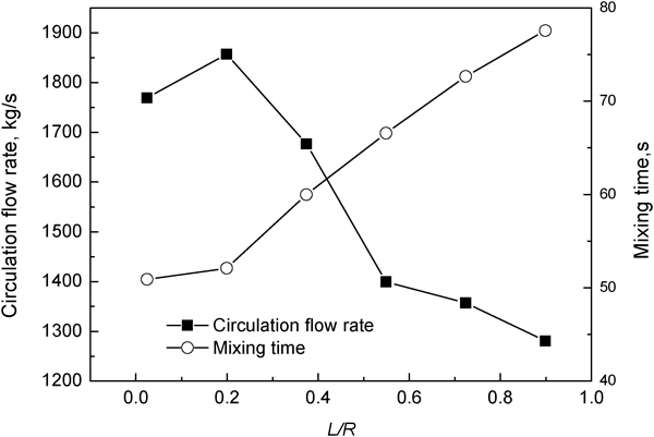
Effect of included angle on circulation flow rate and mixing time in RH degasser (θ = 0)
Figure 8 also shows that the mixing time increases with increasing dimensionless distance because the position of the gas–liquid plume in the ladle is the key factor for mixing efficiency in the RH degasser. The closer the distance between the gas–liquid plume and the ladle centre, the shorter the mixing time.
Figure 9 shows that for the RH degasser with side–bottom blowing, when the dimensionless distance is equal to 0·2, the circulation flow rate decreases with the increasing included angle and then reaches its minimum value when the included angle is equal to π. The reason is as follows. With the increase in the included angle, the distance between the gas–liquid plume in the ladle and the up snorkel increases, so less liquid steel can flow into the up snorkel.
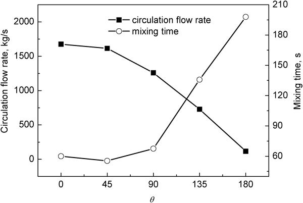
Effect of distance between bottom blowing location and ladle centre on circulation flow rate and mixing time in RH degasser (L/R = 0·2)
Figure 9 also shows that the mixing time decreases with the increasing included angle; first, it reaches its minimum value when the included angle is equal to π/4 and then increases. The position of the gas–liquid plume is the key parameter for the mixing in the ladle. The flow and mixing at both side regions of the line between two snorkels in the ladle are stagnant and slow when the included angle is zero. However, if the included angle is π/4, the gas–liquid plume can stir this region effectively. Meanwhile, the circulation flow rate remains almost unchanged because the gas–liquid plume in the ladle is still near the up snorkel. Thus, the mixing time reaches its minimum value when the included angle is π/4. On the other hand, the distance between the gas–liquid plume in the ladle and the up snorkel increases with the increasing included angle. Consequently, the less liquid steel can flow into the up snorkel, and the kinetic energy from the down snorkel decreases gradually. Thus, the mixing time increases with the increasing included angle when the included angle is larger than π/4.
In order to achieve a large circulation flow rate and a small mixing time to improve the productivity rate during the RH refining process, as shown in Figs. 8 and 9, it can be concluded that 0·2 and π/4 are the optimum values for the dimensionless distance and the included angle in the present work.
Conclusions
A numerical method is used to investigate the flow field and the mixing characteristic in the RH degasser with side–bottom blowing. The effect of ladle bottom blowing location on the circulation flow rate and the mixing time in RH degasser has been investigated, and the following conclusions can be drawn.
For RH with side–bottom blowing, the stream flow in the up snorkel, the vacuum chamber, the down snorkel and the ladle forms a large rectangular circulation zone, so ladle bottom blowing can enhance the circulation flow rate and improve the mixing efficiency in the RH degasser.
For RH with side–bottom blowing, when the included angle of the line between bottom blowing location and ladle centre and the line between two snorkels is zero, the circulation flow rate increases initially with increasing dimensionless distance between bottom blowing location and ladle centre and then decreases. In addition, the mixing time increases with increasing dimensionless distance. When the dimensionless distance is 0·2, the circulation flow rate decreases with the increasing included angle, and the mixing time decreases initially with the increasing included angle and then increases.
The optimum values for dimensionless distance and included angle to achieve large circulation flow rate and small mixing time are 0·2 and π/4 in the present work.
Footnotes
Acknowledgements
This work was supported by the National High-Tech R&D Program of China (grant no. 2009AA03Z530), the National Natural Science Foundation of China and Shanghai Baosteel (grant no. 50834010), 111 Project (grant no. B07015), the Fundamental Research Funds for the Central Universities (grant no. N100409007) and the Doctor Startup Foundation of Liaoning Province (grant no. 20111009).