
Abstract
Understanding the shrinkage behaviour of a steel billet is very important for designing the continuous casting mould, and conversely, a well designed mould is beneficial when matching the shrinkage behaviour of the billet. The shrinkage behaviour of a billet is hard to measure in situ during continuous casting but can be calculated by numerical simulation. A three-dimensional finite element model has been built to simulate the thermal and stress fields of the billet in the mould. The dynamic thermal boundary condition, the effect of ferrostatic pressure and the temperature dependent thermophysical parameters have been considered in the model. The shrinkage of billet when considering ferrostatic pressure is on average 0·08 mm smaller than when not considering ferrostatic pressure. The temperature and stress distributions are analysed in the present paper, and based on this analysis, a novel petal-like mould was designed and its taper determined. The designed mould has been tested in industrial practice showing better lifetime and billet quality.
Introduction
Today, over 90% of the steels used worldwide is produced via continuous casting. The quality of billets in continuous casting depends largely on the solidification and shrinkage process of molten steel in the mould. Failure to compensate for shrinkage of the solidified shell within the mould can result in surface and subsurface cracks and, especially, reduced mould heat transfer; the latter contribution to surface and subsurface cracking as well as possible shape problems, such as rhomboidity. Hence, the mould is one of the most important areas in a continuous casting machine, and an optimised mould taper is critical to prevent the formation of gaps between the strand and mould. Optimised taper relies on accurate predictions of temperature, deformation and stress distributions during the solidification process. However, the solidification of molten steel occurs at a very high temperature, and for both economic and technical reasons, it is difficult to acquire the shrinkage curve of the billets through experimental determination. The development of computer simulation technology created an effective way to optimise and design this process by simulation.
Since as early as the 1970s, much effort has been made to develop a heat transfer model for continuous casting.1, 2 Based on these investigations, some researchers built the stress field mathematical model and made an analysis by the coupled thermomechanical finite element method.3 – 5 Li and Thomas6 built a two-dimensional slice model for billets; the thermomechanical behaviour of billets was then simulated with three types of mould configuration, which produce respectively a hot corner, a cold corner and an equal surface temperature around the perimeter. In this work, optimal taper profiles were predicted according to the shrinking distortion of the billets. A two-dimensional thermoelastoplastic finite element model has been built by Han et al. 7 to analyse the thermomechanical behaviour of the continuous casting strand. This model considered the effect of microsegregation of solute elements using the thermomechanical model of mushy zone and δ/γ phases. With a mathematical billet thermal and solidification model, Chow et al. 8 have designed a new mould taper for steels of high and low carbon grades in high speed continuous casting.
A billet mould with an inner cavity shaped like a petal regulates mould heat transfer and cooling of the solidified shell during its travel through the shaped portion of the mould.9 In the authors’ previous work,10 – 12 a two-dimensional slice model was established to study the solidifying and shrinking behaviours of the billets in a petal-like inner cavity mould. Although reliable predictions can be obtained through analysis with the models, it is still necessary to predict accurately the three-dimensional heat transfer and mechanical state in the mould.13 In the present paper, a three-dimensional finite element model was made to calculate the thermal and stress fields in the billets in a petal-like inner cavity mould. This work may be regarded as a follow up to the authors’ previous study devoted to better understanding the solidification and shrinking process of molten steel in the mould. A dynamic loaded boundary condition was used to replace the movement of the billet in the mould. Ferrostatic pressure has a significant influence on the distortion of the shell during solidification; thus, ferrostatic pressure was considered in the model. Temperature distribution, shell thickness, stress evolution and shrinking distortion for three kinds of billets were studied by this model. The mould taper was optimised based on the calculated results.
Simulation model
Assumptions
Because continuous casting is a very complex process, the following assumptions were made to simplify the model:
neglecting the heat transfer between the meniscus and the atmosphere
it is assumed that the material of the billet follows the von Mises yield criterion
no flow effect of the liquid steel in the billet was considered.
Governing equations
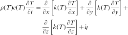
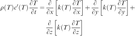
Solidification with a phase change of the molten billet during continuous casting is an unsteady state process. Therefore, the three-dimensional unsteady state heat conduction equation was solved first. The heat governing equation was given in equation (1)14

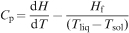
The latent heat generated during the phase change of the billet from liquid to solid in the solidification process C
p is known to be15
Simulation parameters and boundary conditions
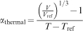
As the temperature of molten steel decreases continuously with phase changes during continuous casting, it is necessary to use varying material parameters. The varying parameters include density, heat conductivity, specific heat, thermal expansion, elastic modulus and yield stress.17 The thermal distortion of the billet depends on the coefficient of thermal expansion α
18
Operating condition of three different steels
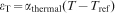
The pouring temperature was defined as the initial temperature in the thermal field simulation. According to the Savage–Pritchard law,19 the heat flux in the mould interface can be described as a time dependent function. In the present model, the heat flux function is given as9
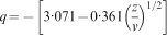
A coordinate dependent thermal boundary condition was dynamically loaded to simulate the relative movement of the billet within the mould. The billet moves downward in the mould, so the heat flux is loaded upward along the billet surface. As shown in Fig. 1, at the initial time (t = 0), the heat flux started to be loaded from the meniscus (z = 0). At t = nΔt (Δt is the time step), the heat flux was loaded at the surface nΔz (Δz = Δt·v) away from the meniscus. That is to say, at each time step, the heat flux at each location of the billet surface was loaded with the calculation of equation (7). In this work, the continuous casting speed was set at 2 m min−1.
Schematic diagram of dynamic loading thermal boundary condition
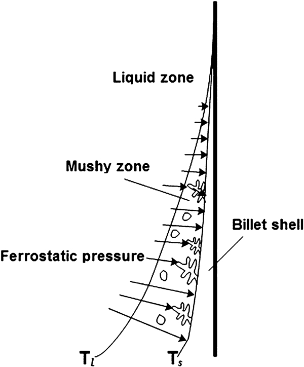
For stress analysis, the displacement constraint at the z direction was loaded at the bottom face of the billet, while the outside surface of the billet was free. The shell of the billet was pressed toward the outward direction by the ferrostatic pressure of the molten steel. In general, the ferrostatic pressure was imposed directly on the internal surface of the billet shell, namely, the solidus line T s, as shown in Fig. 2. In addition, there exist equiaxed crystals and dendritic crystals in a mushy zone. The ferrostatic pressure was not transferred to the surface of the billet shell when it was imposed on the equiaxed crystals. The dendritic crystals usually form close to the surface of the billet shell, so when the ferrostatic pressure was imposed on the dendritic crystals, it would be finally transferred to the surface of the billet shell. In view of the above analysis, it is feasible to just impose the ferrostatic pressure on the internal surface of the billet shell. In the simulation, an eight-node element with six faces was used. In a case where the temperatures of the six faces of an element are all above (in mushy zone or liquid zone), or all below (solid zone) the solidus, the ferrostatic pressure should not be loaded. In the case where the current element locates at the solidus line, the ferrostatic pressure should be loaded.
Schematic of how ferrostatic pressure was loaded at internal boundary
Petal size determination
The application of an excessive taper to the petal-like inner cavity to change the size of the petal in the casting direction causes the mould inner cavity to become more of the traditional round shape close to the mould exit. The petal geometry in the upper part of the mould can accommodate the shrinkage of the billet shell without distortion of the shell. When the convex billet faces formed in the upper part of the mould move downward into the more rounded part of the mould, the billet will suffer a slight shaping from the mould wall. Therefore, the solidified shell can fully contact with the mould wall, which leads to a more uniform temperature and stress distribution. As a result, the petal-like mould can avoid some quality problems, such as surface and subsurface cracks and breakouts. The authors’ previous work already validated that the mould with six petals was the better one, so only the three-dimensional mould with six petals was analysed in the present work.
A three-dimensional round model was built to calculate the total shrinkage of the billet from the meniscus to the exit of the mould. The results of the total shrinkage (maximum shrinkage) for three steels are shown in Table 2. The total shrinkage was used to determine the original size of the petal, as shown in Fig. 3, and the detailed scheme was described in the authors’ previous paper.10 This enabled the start of the thermal and stress simulation by which the taper can be calculated.
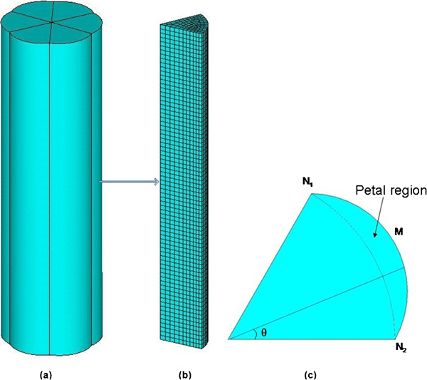
a solid model, b one-sixth three-dimensional finite element mesh model and c one-sixth cross-section of solid model
Results of total shrinkage of round billet
Because the model is symmetrical, only one of the six petals was calculated to save the computer time. Figure 3 shows the solid model, the finite element mesh model and the one-sixth cross-section of the solid model. The length of the billet is 700 mm, and the radius of the cross-section is 103 mm. Because the temperature varies rapidly close to the billet surface, the mesh was refined gradually from centre to surface.
Results and discussion
Figure 4 shows the calculated thickness of the billet shell for the three steels, which when compared with the measurements of Li and Thomas20 shows good agreement. Figure 5 shows the surface temperature distribution along the continuous casting direction. Near the meniscus, the liquid steel suddenly contacts the chilled mould, producing intense cooling. Therefore, a significant temperature decrease was found near the meniscus. The intense cooling zone is not big because the solidified shell began to form rapidly. Accompanying the formation of the solidified shell, the latent heat is released, which makes the temperature decrease slowly (20 mm below meniscus). With the increasing shell thickness, the solidification front moved toward the interior of the billet, and no latent heat directly affects the temperature of the billet surface. Moreover, the solidification shell can still contact the mould due to the ferrostatic pressure. Therefore, the temperature of the billet surface falls rapidly below 250 mm. Over the next 400 mm, the temperature drop decreases slowly because a large and static air gap has formed in this area that reduces the thermal transfer significantly. The steel x42 has an obvious difference in temperature profile with the other two steels due to the difference of equivalent specific heat21 shown in Fig. 6. The steel x42 has a smaller range of phase change, and the latent heat released is also less. The reason is that steel x42 has a different peritectic transformation process (L+δ→δ+γ) than the other two steels (L+δ→L+γ).
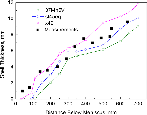
Thickness predicted of billet shell for three steels and comparison with experimental measurements of Li and Thomas20
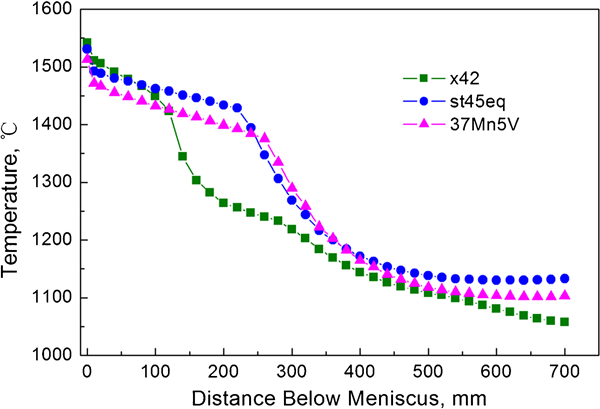
Temperature predicted on shell surface of billet in mould for three different steels
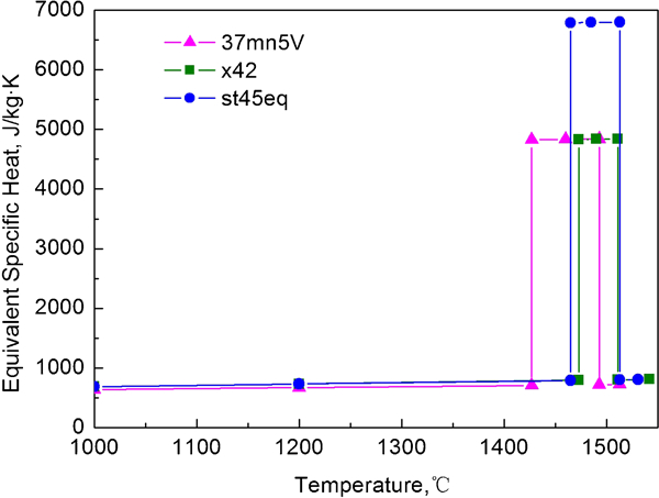
Variation of equivalent specific heat with temperature for three steels
Figure 7 gives the temperature distribution along the petal circumference (N1–M–N2 as shown in Fig. 3) at the exit of the mould. Obviously, the temperature in the petal centre is lower than that in the petal edge due to the petal shape of the billet; the heat extracted from the billet along the normal direction of the billet surface leads to a non-uniform heat transfer in the billet.
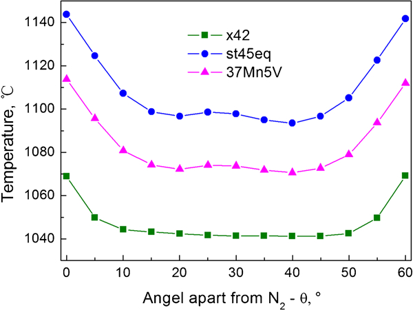
Temperature profiles along petal circumference of shell surface at exit of mould
The displacement of the nodes on the surface of the billet is shown in Fig. 8. The steel x42 has a larger displacement than the other two steels, which is attributed to the larger shrinkage increment of steel x42 with a temperature decrease, as shown in Fig. 9. Near 200 and 500 mm below the meniscus, the surfaces of steels 37Mn5V and st45eq move outward because of the slower temperature decrease as compared with the neighbouring parts. Moreover, the petal centre shrinks faster than the petal edge for all three steels, which agrees with the temperature profiles shown in Fig. 7. The shrinkage of steel 37Mn5V, considered both with and without ferrostatic pressure, is shown in Fig. 10. The former is obviously smaller than the latter because the ferrostatic pressure acts on the inner surface of the shell against shrinkage. The ferrostatic pressure has no significant effect on the shrinkage near the meniscus (liquid zone) and the exit of the mould (strong shell).
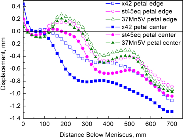
Displacement of nodes on billet surface
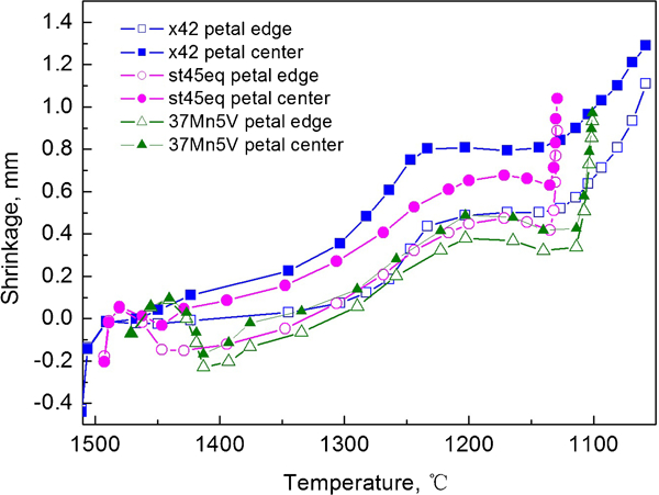
Variation of shrinkage with temperature for three steels
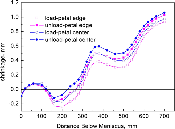
Comparing shrinkages of 37Mn5V with and without loading ferrostatic pressure
The distribution of stress and temperature from the billet centre to the surface at the mould exit is given in Fig. 11. The result is consistent with Weiner and Boley’s22 analytical solution. The stress rises at ∼85 mm from the billet centre, which takes place in the mushy zone. The tensile stress has a maximum value at 97 mm from the billet centre for steels st45eq and 37Mn5V and at 92 mm for steel x42. Then, the stress decreases rapidly, which occurs in the solid area, and the tensile stress transforms into compressive stress. Owing to the subsurface shrinking faster than the surface, the surface is under compressive stress, which accordingly causes the tensile stress in the subsurface near the solidification front that may lead to subsurface cracks.20 At the surface of the billet, the compressive stress reaches the maximum value. Therefore, it is not easy to have surface cracks at the mould exit.
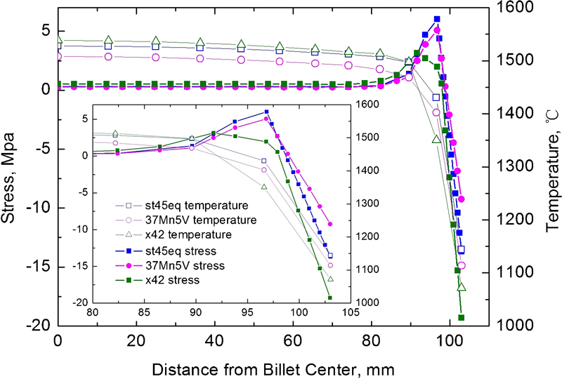
Stress and temperature predicted from billet centre to surface at mould exit
Mould taper design and test
In order to avoid air gap formation, the mould taper should follow the shrinkage of the shell. Although the approach usually applied to mould design is a universal taper for a range of steel grades, in the present paper, two tapers would be needed because of the very different shrinking rules for the steels studied. For example, if steel x42 is cast in the mould with a taper designed for steels st45eq and 37Mn5V, a large gap might form between the billet and the mould. The gap will reduce the heat transfer significantly. Thus, the solidified shell will be insufficiently strong to prevent breakout. On the other hand, if steel st45eq or 37Mn5V is cast in the mould with the taper designed for steel x42, the billet possibly may not be pulled smoothly, which might lead to hot tearing and subsequent billet fracture.
According to the displacement of the billet surface nodes, the taper of the mould can thus be designed as shown in Fig. 12. Because the displacement profiles of steels st45eq and 37Mn5V are similar, their mould tapers can be designed by an average approach. The designed tapers for the petal centre and edge are shown in Fig. 12a . The curve of the taper can be divided into four stages. In stage I, the billets are molten or just have thin shells under the influence of ferrostatic pressure, so there is almost no taper in this stage. However, the petal centre curves outward due to the different shrinkage for the petal centre and petal edge. With the billet shell shrinking fast due to the phase change, the taper increases accordingly to avoid a gap generating in stage II. In addition, the difference of the shrinkage between petal centre and edge becomes smaller; hence, the petal disappears at ∼360 mm above the mould exit. The mould has no taper in stage III and then has a taper to adapt for the shrinkage of the billet in stage IV, according to the displacement curve. According to the shrinkage of steel x42, the taper is designed with two stages given in Fig. 12b . In stage I, there is no taper for the petal edge at the beginning, and the taper appears at 580 mm above the mould exit. The petal centre has a continuous taper until the petal disappears at 500 mm above the mould exit. In stage II, the tapers of the petal edge and petal centre almost overlap each other below 500 mm from the mould exit, that is, the mould inner cavity becomes a traditional round geometry. This design makes the billets round when they exit the mould.
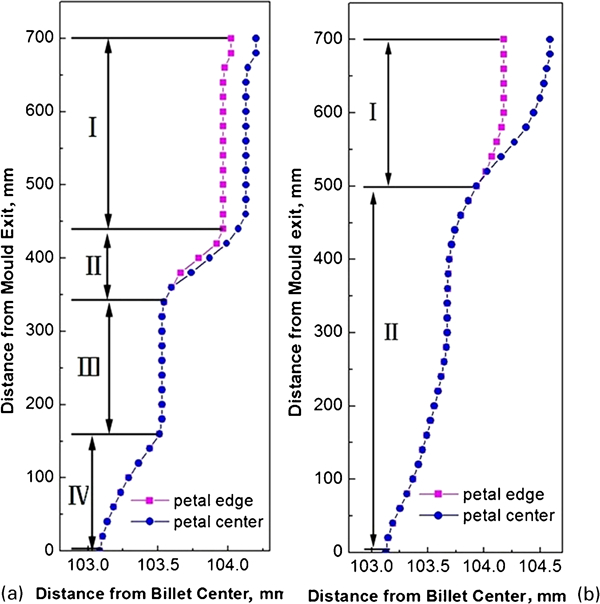
Taper profile designed
The petal-like moulds have been applied on one strand of a six-strand billet caster in China. The test data were gained by using the petal-like mould under industrial conditions, and the operational processing of the petal-like mould was the same as traditional moulds. Compared with the traditional moulds (200 heats), the petal-like mould had a higher lifetime (322 heats). Thirty-five different steel grades were cast. Table 3 shows the quality of the billets produced with different moulds: strand 2 utilising the petal-like mould and the other strands conventional moulds. The crystallisation structures are divided into several classes, and the first class, which has the most refined grains, is the best. The percentage of heats greater than the third class and the total heats is an evaluation parameter in Table 3, which shows that the crystallisation structures of the second strand are better than those of the other strands. Surface cracks occur only in the first and sixth strands. The subsurface crack, centre crack and centre porosity were not found in all six strands. Compared with the other five moulds, the petal-like mould is better or equivalent.
Quality of billets in petal-like mould compared with traditional moulds
Conclusions
A transient, three-dimensional, finite element model has been proposed to simulate the temperature, stress and shrinkage of the billet in the mould during continuous casting. The effects of ferrostatic pressure are considered in this model. The tapers for petal centre and edge have been designed according to the shrinkages of the petal-like mould, and the following conclusions can be made:
The temperature decreases fastest at 250–400 mm below meniscus for steels st45eq and 37Mn5V and at 130–200 mm below meniscus for steel x42.
Compared with conventional moulds, the petal-like mould exhibits better performance in terms of lifetime and billet quality.
The shrinkage of the billet when considering ferrostatic pressure is smaller than that without considering ferrostatic pressure. The difference value has a maximum (0·15 mm) at 490 mm below meniscus.
There exists tensile stress in the mushy area and compression stress in the solid phase area; moreover, tensile stress reaches a maximum near the solidification front, and compression stress reaches maximum at the billet shell surface.
There are four stages of the taper for steels 37Mn5V and st45eq and two stages for steel x42. The petal disappears at 360 mm above the mould exit for steels 37Mn5V and st45eq and at 500 mm above the mould exit for steel x42.
Footnotes
Acknowledgements
This work was supported by National Natural Science Foundation of China (No. 50601003 and 50971032,51071035), the Fundamental Research Funds for the Central Universities, and Liaoning BaiQianWan Talents Program.