
Abstract
CSN BF no. 2 has only three hot blast stoves. Owing to the operational risks as well as output losses associated with the BF operation with just two hot blast stoves, the revamping time of this equipment becomes a crucial issue, requiring special attention in each phase of the project from planning to execution so as to shorten the time as much as possible. According to this context, the present paper describes in detail the main technologies used in the last revamping of hot blast stoves carried out in February 2007. These technologies included an accelerated cooling down curve, air conditioning system (good working condition) and convection heating system, which in association with an innovative construction methodology, involving movable and multilevel platforms, has allowed the project to be completed from blow to blow in a record time of just 67 days and 10 h, resulting in a reduction of costs around R$3·4m.
Introduction
In February 2007, after ∼26 years in operation, the Companhia Siderúrgica Nacional (CSN) BF2 hot blast stove no. 1 was completely repaired. The revamping involved total replacement of the refractory lining and changing of one cast iron beam and two pieces of the Checker Chamber bottom grate. Table 1 describes the main features of the CSN BF2 hot stove design, and Table 2 presents a summary of the shaped and unshaped materials (bill of materials) according to the refractory lining design. The total refractory material weight is ∼2·364 t, involving 30 different technical specifications and more than 50 different shapes.
Main design features of CSN BF2 hot blast stoves
Shaped and unshaped materials: refractory lining design
The BF operating with only two hot blast stoves involves risks and production losses. Therefore, the revamping time becomes a crucial issue requiring special attention in each phase of the project from planning to execution so as to shorten it as much as possible. According to this context, the present paper describes in detail the main technologies used in the last hot blast stove no. 1 revamping carried out in February 2007; accelerated cooling down curve, good working conditions (thermal comfort) and convection heating system, which in association with an innovative construction methodology involving movable and multilevel platforms have allowed completion of the project from blow to blow in record time.
Objective
The present work had the following targets according to the total quality dimensions:
safety: zero injury (number one priority)
delivery: maximum repair time of 70 days from blow to blow
quality: a minimum hot blast stove campaign of 30 years in operation without intermediary repairs
cost: strict adherence to budgeted cost.
Methodology
Safety plan
Execution procedures of all services were elaborated describing the sequence of the activities, duration, responsibility and all necessary resources: manpower, materials and equipment. In light of such procedures, risk analyses were formulated, including all personal and collective safety equipment required for a risk free execution of the activities. All contractors’ and subcontractors’ personnel involved were duly trained, and these included RIP (refractory services), SANKYU (mechanical services), MILLS (scaffolds) and THERMOJET (cooling down, thermal comfort and heating up). The training included orientation training aimed to identify specific hazards in the BF area job site and risk analysis training (hands on and hands off) on all activities. The safety plan comprised the following actions:
dissemination of CSN safety regulations
CO monitoring plan
emergency plan
evacuation route
meetings involving all CSN’s and contractors’ team leaders and supervisors.
Environment
All demolished refractory material was sold to third parties and later on recycled by the refractory industry, resulting in extra revenue and environmental preservation.
Preassembling
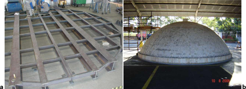
In order to assure service quality and adherence to the project time schedule, several activities were carried out: identification of all refractory shapes, packing according to the assembling sequence and preassembling training sessions of the main and most critical activities, such as the following:
mechanical services: preassembling of movable and stationary platforms
refractory services: preassembling of manholes, checker chamber and combustion chamber walls and dome.
Figure 1 shows preassembling of the stationary platform and dome dense refractory lining.
Training on critical activities
Logistics
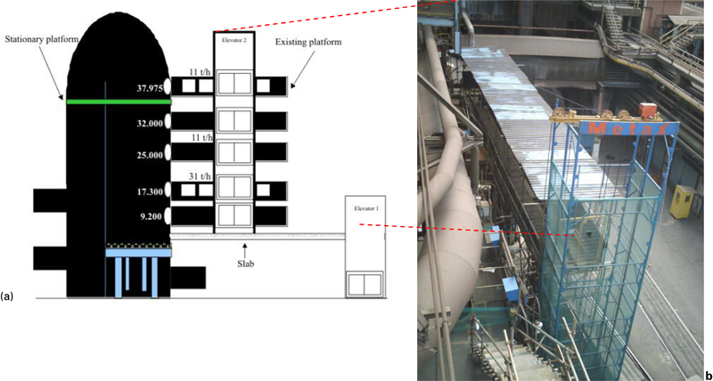
In a project of this nature with several job sites at different elevations, working simultaneously, one of the key factors to guarantee compliance with the duration of the rebricking activities refers to the logistics of supply in order to avoid any interruption of the services due to the lack of materials.
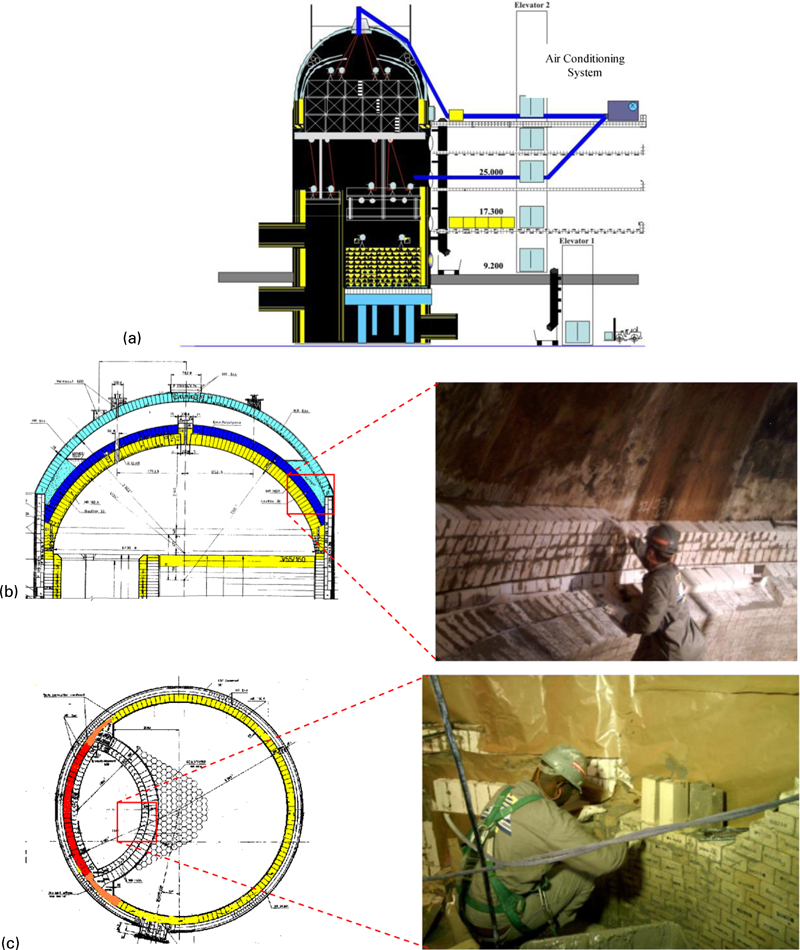
Owing to the physical restrictions of the layout at the CSN BF 2 hot blast stove area, the planned assembly of two freight elevators, transfer tables, five platforms and one hoist and the opening of four new manholes at different elevations by torch cut were planned as schematically shown in Fig. 2.
Materials supply system
Contingency plan
Again, in order to eliminate possible causes of service interruption as well as strict adherence to the project time schedule, a contingency plan was elaborated, covering the following critical points:
freight elevators: spare engine, pulley belts, closing door device and mechanic maintenance during the complete period of the project
two spare winches ‘velox’ (elevations 8000 and 37 975)
two systems for removing demolished material (piping) with two buckets; one from elevation 37 500 to 9200 and another from 9200 to ground zero.
Manpower
Table 3 shows the planned manpower on an 8 h shift basis for demolition and rebricking phases, including support teams.
Manpower per work shift
Time schedule
From a basic planning perspective, the project was split up into four steps: cooling down, demolition, rebricking and heating up. Table 4 shows, in a macro way, the project time schedule (critical path), totaling 70 days from blow to blow.
Project macrotime schedule: critical path
Results and discussion
Safety
During the execution period of the project, safety teams made rounds in all the work shifts to identify and eliminate immediately unsafe conditions. Safety audits were also carried out for monitoring safe behaviour index in connection with the main safety instructions, i.e. CO monitoring, confined space, work at high places, etc. (Fig. 3). The safe behaviour index is the percentage relationship between the number of complied safety standards and the total number of audited safety ones. The main project safety indicators are as follows:
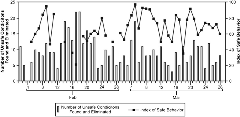
Number of unsafe conditions found and unsafe behavior index (period of time: February–March 2007)
training: 10 122 h (37 h/man)
injuries: one with and two without lost time
injury frequency rate: 6·10
application of the conduct manual: one reprimand, two cases of job site removals and 10 dismissals.
Figure 4 shows the main occurrences reported according to Bird Pyramid.1
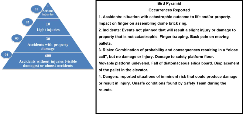
Main safety records
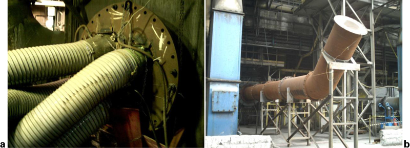
Accelerated cooling down
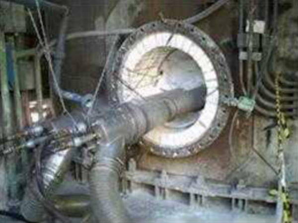
Considering that the refractory lining would be totally demolished without any reuse of material, there was therefore no restriction regarding cooling down. Ideally, it should be done as quickly as possible. Based on that, a planned accelerated cooling down curve was carried out, only 86 h (Fig. 5), by blowing cold air and spraying water mist at the lower temperature range. A ventilation system was assembled at the checker chamber bottom (cold air inlet) as well as thermocouples at the temporary chimney exit in order to track the temperature drop (Fig. 6). The cooling down activity was completed successfully in 4 days and 6 h with a positive clearance of 18 h in relation to the planned time schedule (5 days).
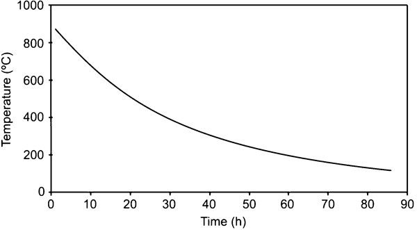
Accelerated cooling down curve (hot face)
Accelerated cooling down
Work conditions (air conditioning system)
Good working conditions are absolutely necessary to achieve a high productivity level. In this specific case, special care was taken considering that services were supposed to be performed in the confined space of the hot blast stove, separated by multilevel platforms and to be done in Brazilian summertime, under pretty high temperatures. In view of this fact, an air conditioning system and a dedusting system were installed to ensure fresh, recirculating air on every work front (Fig. 7). The temperature and atmosphere, O2 and CO, on several job sites were monitored at the beginning of each work shift.
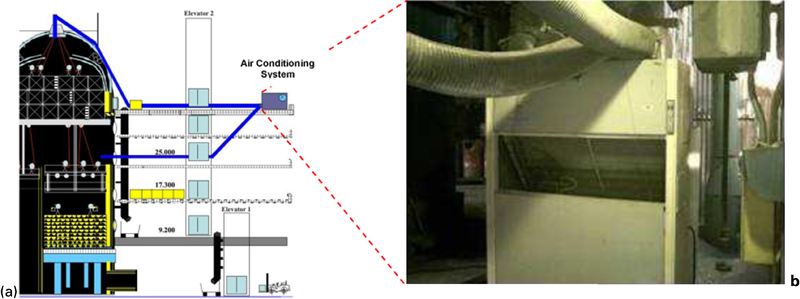
Air conditioning system (thermal comfort)
Demolition
The major concern regarding refractory lining demolition was the safety of personnel. It refers to a service executed in confined space in 42 m high equipment demanding the use of a lifeline.
A deflection plate was installed in the burner opening at the combustion chamber bottom. Refractory materials from the demolition were bulldozed and dumped in a bay in the hot blast stoves area. As mentioned earlier, rubble removal systems were also assembled, just in case the burner openings used for the materials exit were blocked.
Demolition services started outside by opening the dome central flange. Lateral protection and lifelines were installed on the hot blast stove top to secure personnel safety. Air conditioning and dedusting systems were also installed before allowing people into the equipment. After dome demolition, a movable platform was assembled at the combustion chamber area (platform 1, P1). Checker chamber and the division wall were demolished with workers standing on the checker chamber bricks while the combustion chamber was torn down by using a movable platform. At elevation 32 600, the demolition services were temporarily interrupted to assemble a stationary platform (platform 2, P2) and brick rings in order to allow rebricking activities of the dome in parallel to the demolition of the lower part of the hot stove (beneath stationary platform). The combustion chamber movable platform P1 was reassembled underneath the stationary platform P2, and the demolition services continued on to the equipment bottom following the same procedure, as explained earlier. Figure 8 illustrates the demolition services.
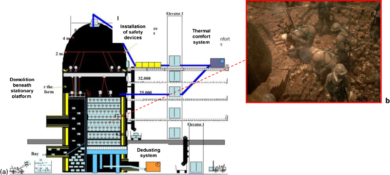
Demolition of refractory lining and dome rebricking
Demolition was completed in 11 days and 16 h with a negative clearance of 16 h in relation to the planned time schedule (11 days). The main causes of the delay were the following:
deformation of the deflection plate, undersized by ∼13 mm
blocking of the materials exit because the burner opening refractory lining was not demolished; in addition, the flange around the burner opening was not torch cut
lack of mechanics to respond quickly to the required changes; deflection plate, bay and torch cutting
unskilled jackhammer operators.
Rebricking
Dome
After assembling the stationary platform P2 and welding the brick rings, work started immediately on the rebricking activities of the upper courses of the checker and combustion chamber ring walls (job site 1, C1). The dome roof was rebricked by using scaffolds on stationary platform P2. As mentioned before, the dense refractory lining of the dome roof had already been preassembled and the pieces of each course identified according to assembly sequence.
Combustion and checker chambers
After demolishing the checker bricks, hematite bricks were removed for blasting and the cast iron grate covered with wood boards to allow the assembling of a new movable platform at the checker chamber (platform 3, P3), which was also supported by the dome region stationary platform P2. The movable platform P3 was lifted up to the 6000 elevation and the wooden board covering removed. One beam and two pieces of cast iron grate were replaced.
Before starting rebricking activities, a topographic survey was carried out. The division wall and ring walls of the combustion and checker chambers, except for the last course (jacket) of the combustion chamber, were assembled simultaneously up to elevation 10 000 (job sites 2 and 3, C2 and C3, respectively). Thereafter, a new movable safety platform (platform 4, P4) was assembled on the checker chamber grate and also supported by the dome stationary platform P2. The steel cables supporting the mentioned safety platform P4 were run through the existing holes in the movable platform floor that had been assembled earlier P3.
The safety movable platform P4 was lifted and parked at elevation 10 000. Rebricking activities of the checker were then started (job sites 4, C4) in parallel to the continuation of the ring walls rebricking activities C2 and C3. As the checker rebricking progressed C4, the safety platform P4 was moved and parked at a new elevation, thus allowing for job sites 2, 3 and 4 to run simultaneously. At the same time, the supplying manholes, which were cut open in the shell, were welded and tested using penetrating liquid tests. Figure 9 shows job sites 1, 2, 3 and 4 rebricking activities running in parallel.
Rebricking activities in parallel: dome, C1, combustion and checker chambers ring walls C2 and C3 and checker C4
After finishing the ring wall rebricking activities C2 and C3, movable platforms of the combustion and checker chambers P1 and P3 were parked underneath the dome stationary platform P2. Then, the rebricking of the combustion chamber third course (jacket) was started (job sites 5, C5), by using scaffolds, in parallel with the conclusion of checker rebricking activities C4.
Right after completing the checker rebricking activities C4 and combustion chamber third course (jacket) C5, the platforms started to be disassembled in the following sequence: safety movable platform P4, checker chamber movable platform P3 and combustion chamber movable platform P1. In order to disassemble the stationary platform P2, the free section of the combustion chamber was covered with wooden boards.
Upon removing the stationary platform P2 and disassembling the combustion chamber scaffolds, closure of the combustion and checker chambers ring walls at the brick ring region was completed. Afterward, the combustion chamber wooden board covering was removed and the division wall and checker up to end elevation finished. Finally, the dome manhole at elevation 37 975 was closed.
Rebricking activities included in the critical path were executed in 41 days and 14 h, with a positive clearance of 10 h in relation to the planned time schedule (42 days). Nevertheless, a number of problems compromised a quicker completion, namely:
rework resulting from design no conformities and supervision failures
rework of manholes and checker rebricking due to unskilled bricklayers
absenteeism, particularly at weekends
equipment failure, such as the hoist and ‘velox’ winch
lack of materials due to materials supply coordination, especially during the critical time of supplying five job sites simultaneously
need to repair the safety platform, which was damaged during moving without taking the locking pins away (a serious problem from a safety point of view).
Convection heating up
The refractory lining heating up curve must be carefully planned so as to reduce production losses, that is, as short as possible while preserving the equipment, thus preventing crack nucleation and propagation.2, 3
The temperature critical gradient ΔTC, the temperature difference between refractory lining hot and cold faces that starts crack propagation, was calculated from refractory material thermomechanical properties,2
–
4 equation (1), and limited to 200°C
In addition, the temperature at the cast iron grate must be limited to 350°C.
Convection heating was used (Fig. 10) in order to minimise the temperature gradient between the different regions of the equipment.5, 6 Aligned thermocouples were installed on the hot and cold faces of the dome roof dense refractory lining as well as underneath the cast iron grate for temperature monitoring purposes. Figure 11 shows the planned versus actual heating up curves, totaling 9 days and 7 h (223 h).
Convection heating up system
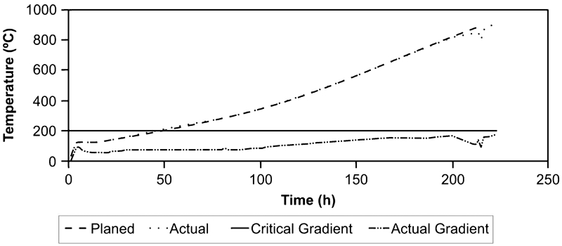
Heating up curve (hot face of dome roof dense refractory lining)
The heating up phase, including mechanical services required to bring the hot blast stove into operation, was completed in 9 days and 22 h, with a positive clearance of 50 h in relation to the planned time schedule (12 days).
Time schedule
The project was completed in 67 days and 10 h, that is, 2 days 14 h earlier than originally planned (70 days). The introduction of new technologies associated with an innovative construction methodology has played a major role in shortening the hot blast stoves revamping time (Figs. 12 and 13).
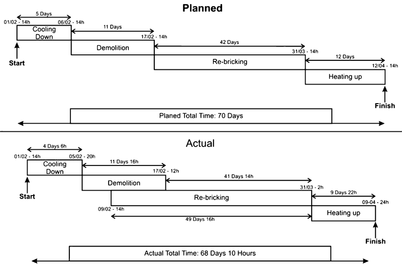
Revamping of hot blast stove no. 1 (2007)
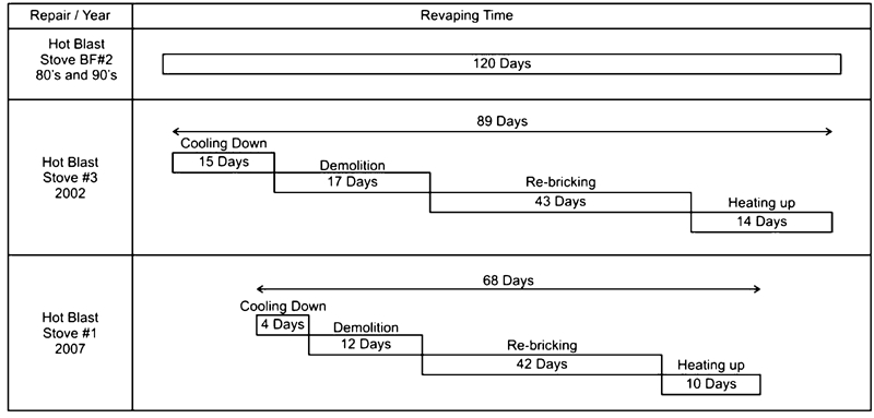
Time schedule of CSN BF 2 hot blast stove revamping
Economic benefits
The total cost of the no. 1 hot blast stove revamping was $14m; this is a reduction of $3m compared to no. 3 hot blast stove revamp carried out in 2002 on an emergency basis (Fig. 14). This fact shows clearly the benefits arising from monitoring and planning adequately the campaign of such equipment.
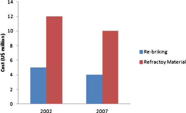
Cost of CSN BF 2 hot blast stoves revamping
The 2·5 day saving results in an anticipated savings of around R$375 000 in terms of contribution margin in equivalent tons of steel slabs. However, the greatest benefit of all by shortening revamping time was to eliminate operational risks associated with running the blast furnace with only two hot blast stoves: an intangible gain.
Conclusion
The introduction of new technologies, i.e. accelerated cooling down, air conditioning system (good working conditions), convection heating up and innovative construction methodology, and the use of movable and multilevel platforms have allowed the execution of CSN BF no. 2 hot blast stove no. 1 revamping in record time, only 67 days and 10 h from blow to blow, resulting in savings of around $3·4m.